WO2012169045A1 - 無停電電源システム - Google Patents
無停電電源システム Download PDFInfo
- Publication number
- WO2012169045A1 WO2012169045A1 PCT/JP2011/063251 JP2011063251W WO2012169045A1 WO 2012169045 A1 WO2012169045 A1 WO 2012169045A1 JP 2011063251 W JP2011063251 W JP 2011063251W WO 2012169045 A1 WO2012169045 A1 WO 2012169045A1
- Authority
- WO
- WIPO (PCT)
- Prior art keywords
- total
- power
- power supply
- converter
- amount
- Prior art date
- Legal status (The legal status is an assumption and is not a legal conclusion. Google has not performed a legal analysis and makes no representation as to the accuracy of the status listed.)
- Ceased
Links
Images


Classifications
-
- H—ELECTRICITY
- H02—GENERATION; CONVERSION OR DISTRIBUTION OF ELECTRIC POWER
- H02J—ELECTRIC POWER NETWORKS; CIRCUIT ARRANGEMENTS OR SYSTEMS FOR SUPPLYING OR DISTRIBUTING ELECTRIC POWER; SYSTEMS FOR STORING ELECTRIC ENERGY
- H02J9/00—Circuit arrangements for emergency or stand-by power supply, e.g. for emergency lighting
- H02J9/04—Circuit arrangements for emergency or stand-by power supply, e.g. for emergency lighting in which the distribution system is disconnected from the normal source and connected to a standby source
- H02J9/06—Circuit arrangements for emergency or stand-by power supply, e.g. for emergency lighting in which the distribution system is disconnected from the normal source and connected to a standby source with automatic change-over, e.g. UPS systems
- H02J9/062—Circuit arrangements for emergency or stand-by power supply, e.g. for emergency lighting in which the distribution system is disconnected from the normal source and connected to a standby source with automatic change-over, e.g. UPS systems for AC powered loads
-
- H—ELECTRICITY
- H02—GENERATION; CONVERSION OR DISTRIBUTION OF ELECTRIC POWER
- H02J—ELECTRIC POWER NETWORKS; CIRCUIT ARRANGEMENTS OR SYSTEMS FOR SUPPLYING OR DISTRIBUTING ELECTRIC POWER; SYSTEMS FOR STORING ELECTRIC ENERGY
- H02J3/00—Circuit arrangements for AC mains or AC distribution networks
- H02J3/38—Arrangements for feeding a single network from two or more generators or sources in parallel; Arrangements for feeding already energised networks from additional generators or sources in parallel
- H02J3/46—Controlling the sharing of generated power between the generators, sources or networks
- H02J3/466—Scheduling or selectively controlling the operation of the generators or sources, e.g. connecting or disconnecting generators to meet a demand
-
- H—ELECTRICITY
- H02—GENERATION; CONVERSION OR DISTRIBUTION OF ELECTRIC POWER
- H02J—ELECTRIC POWER NETWORKS; CIRCUIT ARRANGEMENTS OR SYSTEMS FOR SUPPLYING OR DISTRIBUTING ELECTRIC POWER; SYSTEMS FOR STORING ELECTRIC ENERGY
- H02J9/00—Circuit arrangements for emergency or stand-by power supply, e.g. for emergency lighting
- H02J9/04—Circuit arrangements for emergency or stand-by power supply, e.g. for emergency lighting in which the distribution system is disconnected from the normal source and connected to a standby source
- H02J9/06—Circuit arrangements for emergency or stand-by power supply, e.g. for emergency lighting in which the distribution system is disconnected from the normal source and connected to a standby source with automatic change-over, e.g. UPS systems
- H02J9/061—Circuit arrangements for emergency or stand-by power supply, e.g. for emergency lighting in which the distribution system is disconnected from the normal source and connected to a standby source with automatic change-over, e.g. UPS systems for DC powered loads
-
- H—ELECTRICITY
- H02—GENERATION; CONVERSION OR DISTRIBUTION OF ELECTRIC POWER
- H02J—ELECTRIC POWER NETWORKS; CIRCUIT ARRANGEMENTS OR SYSTEMS FOR SUPPLYING OR DISTRIBUTING ELECTRIC POWER; SYSTEMS FOR STORING ELECTRIC ENERGY
- H02J2105/00—Networks for supplying or distributing electric power characterised by their spatial reach or by the load
- H02J2105/10—Local stationary networks having a local or delimited stationary reach
- H02J2105/12—Local stationary networks having a local or delimited stationary reach supplying households or buildings
-
- Y—GENERAL TAGGING OF NEW TECHNOLOGICAL DEVELOPMENTS; GENERAL TAGGING OF CROSS-SECTIONAL TECHNOLOGIES SPANNING OVER SEVERAL SECTIONS OF THE IPC; TECHNICAL SUBJECTS COVERED BY FORMER USPC CROSS-REFERENCE ART COLLECTIONS [XRACs] AND DIGESTS
- Y02—TECHNOLOGIES OR APPLICATIONS FOR MITIGATION OR ADAPTATION AGAINST CLIMATE CHANGE
- Y02P—CLIMATE CHANGE MITIGATION TECHNOLOGIES IN THE PRODUCTION OR PROCESSING OF GOODS
- Y02P80/00—Climate change mitigation technologies for sector-wide applications
- Y02P80/10—Efficient use of energy, e.g. using compressed air or pressurized fluid as energy carrier
- Y02P80/14—District level solutions, i.e. local energy networks
Definitions
- AC power is converted into DC power
- DC power that has been converted or DC power of a storage battery is converted back into AC power
- a plurality of uninterruptible power supply devices that supply power to a load are connected in parallel.
- the present invention relates to an uninterruptible power supply system.
- An uninterruptible power supply system disclosed in Japanese Patent Application Laid-Open No. 2011-72068 includes a plurality of uninterruptible power supply devices, a switching circuit that switches to a bypass power supply when there is a failure in the uninterruptible power supply device, A switch for opening and closing the output of the circuit is provided. And the uninterruptible power supply system currently disclosed by patent document 1 enables it to select the connection of a switching circuit and load with a switch, and connects to one uninterruptible power supply, or several A configuration in which two uninterruptible power supply units are connected in parallel can be selected.
- the uninterruptible power supply system disclosed in Patent Document 1 can supply power in a short time even if one of the uninterruptible power supply fails, and the bypass power supply within the time required for repair of the uninterruptible power supply The risk of load stoppage due to power outages can be reduced.
- the conventional uninterruptible power supply system requires improvement in reliability, a plurality of uninterruptible power supply apparatuses are connected in parallel and operated in parallel with a common storage battery.
- the conventional uninterruptible power supply system can connect all the uninterruptible power supply units as long as the total power amount of the uninterruptible power supply is smaller than the total rated power amount regardless of the amount of power required for the load (actual power amount). It is running. Therefore, the conventional uninterruptible power supply system has a problem that the utilization efficiency of a plurality of uninterruptible power supply apparatuses connected in parallel is poor.
- the uninterruptible power supply also includes a converter (forward conversion unit) that converts AC power into DC power and an inverter (reverse conversion unit) that converts DC power into AC power.
- a converter forward conversion unit
- an inverter reverse conversion unit
- the conventional uninterruptible power supply system stops all circuits including the converter and inverter that constitute the stopped uninterruptible power supply unit. ing. Therefore, in the conventional uninterruptible power supply system, in order to supply the necessary amount of power to the load, when restarting the stopped uninterruptible power supply, it is necessary to start all the circuits in order, and the stopped uninterruptible power supply The startup time of the device becomes longer.
- the present invention has been made to solve the above-described problems, and provides an uninterruptible power supply system capable of reducing the power consumption with high use efficiency of a plurality of uninterruptible power supply apparatuses connected in parallel.
- the purpose is to provide.
- the present invention provides a plurality of uninterruptible power supply units that are connected in parallel to a load and that switch power sources that supply power to the load according to the power supply status, and a power source for the uninterruptible power supply unit
- It is an uninterruptible power supply system provided with the control part which controls the operation
- the uninterruptible power supply is composed of a forward conversion unit that forward-converts alternating current power of the alternating current power source into direct-current power, a switching unit that switches between direct-current power converted by the forward conversion unit and direct-current power input from the storage battery, and a forward conversion unit.
- a reverse conversion unit that reverse-converts forward-converted direct-current power or direct-current power input from the storage battery into alternating-current power and supplies the load to the load;
- a control part stops the forward conversion part which does not contribute to supply of the electric energy required for load among several forward conversion parts.
- the amount of power required for the load is small (low load) compared to the total rated power amount output by the activated uninterruptible power supply (forward conversion unit).
- the control unit stops the forward conversion unit that does not contribute to the supply of the amount of power required for the load among the multiple forward conversion units, so that the utilization efficiency of the plurality of uninterruptible power supply devices connected in parallel can be increased. .
- the uninterruptible power supply system according to the present invention stops the forward conversion unit that does not contribute to the supply of the amount of power necessary for the load, it is possible to suppress power loss of the stopped forward conversion unit and reduce power consumption. it can.
- the uninterruptible power supply system according to the present invention stops only the forward conversion unit, the start time of the stopped uninterruptible power supply can be shortened compared to when all circuits of the uninterruptible power supply are stopped. Can do.
- FIG. 1 is a schematic diagram showing a configuration of an uninterruptible power supply system according to Embodiment 1 of the present invention.
- 1 includes an AC input unit 1, an input / output / switching unit 2, a control unit 3, a DC branching unit 4, a storage battery 5, an output unit 6, AC output units 7 and 8, an uninterruptible power supply device. 10, 20, and 30 are included.
- the AC input unit 1 is connected to an AC power source (not shown) and supplies power to the uninterruptible power supply devices 10, 20, and 30.
- the AC power source connected to the AC input unit 1 is a commercial power source or an AC power source such as a private generator.
- AC output units 7 and 8 are connected to a load (computer, communication device, etc.) not shown, and supply power to the load from uninterruptible power supplies 10, 20, and 30.
- a load computer, communication device, etc.
- the AC output units 7, 8 are connected to the load by a three-phase three-wire distribution line.
- the input / output / switching unit 2 switches the connection between the AC input unit 1 and the uninterruptible power supply 10, 20, 30 and the connection between the uninterruptible power supply 10, 20, 30 and the AC output unit 7, 8. To supply power.
- the input / output / switching unit 2 includes maintenance bypass wiring that connects the AC input unit 1 and the AC output units 7 and 8 when performing maintenance work on the uninterruptible power supply 10, 20, 30. .
- the maintenance bypass wiring includes a circuit breaker 71, a transformer 72, a switch 73, a thyristor switch 74, and a contactor 75.
- the circuit breaker 71 is a switch that blocks a large amount of power from flowing suddenly into the maintenance bypass wiring.
- the transformer 72 is an insulating transformer that converts the AC voltage of the AC input unit 1.
- the switch 73 is a switch that connects the transformer 72 and the thyristor switch 74.
- the thyristor switch 74 is a semiconductor switch that can switch the output power of the uninterruptible power supply 10, 20, 30 faster than the contactors 61 to 63 of the output unit 6.
- the contactor 75 is a switch for outputting the AC power of the AC input unit 1 to the AC output units 7 and 8 through the maintenance bypass wiring.
- the input / output / switching unit 2 includes a circuit breaker 11 for blocking a large amount of power from flowing between the AC input unit 1 and the uninterruptible power supply 10.
- the input / output / switching unit 2 includes a circuit breaker 21 between the AC input unit 1 and the uninterruptible power supply 20, and a circuit breaker 31 between the AC input unit 1 and the uninterruptible power supply 30, respectively. It is out.
- the input / output / switching unit 2 includes a transformer 12 that converts the AC voltage of the AC input unit 1 between the AC input unit 1 and the uninterruptible power supply 10.
- the input / output / switching unit 2 includes a transformer 22 between the AC input unit 1 and the uninterruptible power supply 20, and a transformer 32 between the AC input unit 1 and the uninterruptible power supply 30. It is out.
- the input / output / switching unit 2 includes a switch 76 that connects the maintenance bypass wiring and the AC output units 7 and 8, and a switch 77 that connects the uninterruptible power supply 10, 20, 30 and the AC output units 7 and 8. ⁇ 79 are included.
- the uninterruptible power supply 10 includes a contactor 13, an AC reactor 14, a converter 15, an electrolytic capacitor 16, an inverter 17, a transformer 18, and a capacitor 19.
- the contactor 13 is a switch for inputting AC power transformed by the transformer 12 to the uninterruptible power supply 10.
- the AC reactor 14 is a filter for shaping the waveform of AC power input to the uninterruptible power supply 10.
- the converter 15 is a forward conversion unit that forward-converts AC power whose waveform is shaped by the AC reactor 14 into DC power.
- FIG. 2 is a circuit diagram showing a configuration of converter 15 of uninterruptible power supply system 100 according to Embodiment 1 of the present invention.
- the converter 15 shown in FIG. 2 is connected in parallel between three IGBTs (Insulated Gate Bipolar Transistors) 151 connected in parallel between the positive side of the power source and the load, and between the negative side of the power source and the load.
- IGBTs 152 and FWD (Free Wheeling Diode) 153 connected in parallel to each of the IGBTs 151 and 152 are included.
- the converter 15 can forward-convert AC power into DC power by driving the IGBTs 151 and 152 at appropriate timing.
- the loss caused by driving the IGBTs 151 and 152 includes a steady loss caused by energizing the IGBTs 151 and 152 and a switching loss caused by switching the IGBTs 151 and 152.
- FIG. 3 is a timing chart for explaining the switching loss of the IGBTs 151 and 152.
- the waveform shown in FIG. 3 shows the waveform of the voltage V applied to the gate electrodes of the IGBTs 151 and 152 and the waveform of the current I flowing between the collector electrode and the emitter electrode of the IGBTs 151 and 152, respectively.
- the IGBTs 151 and 152 are turned on at the timing when the voltage V applied to the gate electrode falls, and the current I starts to flow between the collector electrode and the emitter electrode.
- the switching time t is as high as 0.25 ⁇ m.
- the converter 15 is not limited to the IGBTs 151 and 152 as long as it is a semiconductor switch, and a bipolar or a thyristor may be used. When bipolar is used, the switching time t is 2.5 ⁇ m, which is slower than when IGBT is used.
- uninterruptible power supply system 100 is a converter that does not contribute to supply of the amount of power required for the load when the amount of power required for the load is small (low load). Is stopped, switching loss P sw and steady loss P c are suppressed, and power consumption is reduced.
- the electrolytic capacitor 16 is a smoothing capacitor for smoothing the DC power forward-converted by the converter 15.
- the inverter 17 is an inverse conversion unit that inversely converts DC power smoothed by the electrolytic capacitor 16 or DC power input from the storage battery 5 into AC power.
- the converter 15 and the inverter 17 have the same circuit configuration because they only differ in whether AC power is forward converted to DC power or DC power is reversely converted to AC power. Therefore, as shown in FIG. 2, the inverter 17 also includes three 151 connected in parallel between the positive side of the power source and the load, and three connected in parallel between the negative side of the power source and the load.
- the configuration includes an IGBT 152 and an FWD 153 connected in parallel to each of the IGBTs 151 and 152.
- the transformer 18 transforms the voltage of the AC power reversely converted by the inverter 17.
- the capacitor 19 is a filter for shaping the waveform of the AC power transformed by the transformer 18.
- the AC power whose waveform is shaped by the capacitor 19 is output from the uninterruptible power supply 10.
- the AC power output from the uninterruptible power supply 10 is output from the AC output units 7 and 8 via the contactor 61 of the output unit 6.
- the output unit 6 includes contactors 61-63.
- the output unit 6 switches the contactors 61 to 63 to connect the uninterruptible power supply devices 10, 20, and 30 to the AC output units 7 and 8, and outputs the AC power output from the uninterruptible power supply devices 10, 20, and 30. Is supplied to the load.
- the uninterruptible power supply 20 includes a contactor 23, an AC reactor 24, a converter 25, an electrolytic capacitor 26, an inverter 27, a transformer 28, and a capacitor 29.
- the uninterruptible power supply 30 includes a contactor 33, an AC reactor 34, a converter 35, an electrolytic capacitor 36, an inverter 37, a transformer 38 and a capacitor 39. Since the configuration of uninterruptible power supply 20 and 30 is the same as that of uninterruptible power supply 10, detailed description will not be repeated.
- the control unit 3 includes a converter control unit 300, converter operation command circuits 301 to 303, inverter operation command circuits 304 to 306, and signal generation circuits 307 to 309.
- the control part 3 is also controlling the operation
- Converter control unit 300 receives feedback values of converter load currents from converters 15, 25, and 35, and adds the input feedback values to supply converters 15, 25, and 35 to supply a necessary amount of power. The total amount of electric power output by is calculated. Furthermore, converter control unit 300 compares the calculated total power amount with the total rated power amount output by the remaining converters when at least one converter among stopped converters 15, 25, and 35 is stopped. Then, the number selection command signal of the converters 15, 25, 35 is output to the converter operation command circuits 301 to 303 of the converters 15, 25, 35.
- Signal generation circuits 307 to 309 receive instructions to start and stop converters 15, 25, 35 and inverters 17, 27, 37 from an input unit (not shown), converter operation command circuits 301 to 303, inverter operation command circuit 304 Instruction signals are output to .about.306.
- the converter operation command circuits 301 to 303 start and stop the converters 15, 25, and 35 based on the number selection command signal output from the converter control unit 300 and the instruction signal output from the signal generation circuits 307 to 309.
- the command signal to command is output.
- the inverter operation command circuits 304 to 306 output command signals for commanding start and stop to the inverters 17, 27, and 37 based on the instruction signals output from the signal generation circuits 307 to 309.
- the DC branch unit 4 includes circuit breakers 44 to 48.
- the circuit breakers 44, 45, 46 are switches that block large power from flowing into each uninterruptible power supply 10, 20, 30.
- the circuit breakers 47 and 48 are switches that block large power from flowing into the storage battery 5 rapidly.
- the uninterruptible power supply 10, 20, 30 includes contactors 41, 42, 43. Contactors 41, 42, 43 are switches for connecting uninterruptible power supply 10, 20, 30 and storage battery 5, DC power converted by converters 15, 25, 35, and DC power input from storage battery 5 It is a switching part which switches.
- the storage battery 5 is commonly connected to the uninterruptible power supply 10, 20, 30.
- the storage battery 5 is composed of two batteries 51 and 52.
- the storage battery 5 is not limited to the case where it is comprised by the two batteries 51 and 52, and may be comprised by a single battery or may be comprised by three or more batteries.
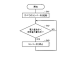
- FIG. 4 is a flowchart for explaining the operation of uninterruptible power supply system 100 according to Embodiment 1 of the present invention.
- converter control unit 300 activates converters 15, 25, and 35 of all uninterruptible power supplies 10, 20, and 30 (step S41). Specifically, converter control unit 300 outputs a number selection command signal for selecting all converters 15, 25, 35 to converter operation command circuits 301-303 of each converter 15, 25, 35, and signal generation circuits 307- 309 outputs an instruction signal for starting converters 15, 25, and 35 to converter operation command circuits 301 to 303.
- Converter operation command circuits 301-303 command each converter 15, 25, 35 to start based on the number selection command signal output from converter control unit 300 and the instruction signal output from signal generation circuits 307-309. A command signal is output. Each converter 15, 25, 35 is activated based on a command signal output from converter operation command circuits 301 to 303.
- the converter control unit 300 includes at least one of the total amount of power output from the converters 15, 25, and 35 to supply the necessary amount of power to the load, and the activated converters 15, 25, and 35.
- the total rated power amount output by the remaining converters is compared, and it is determined whether or not the total power amount is smaller than the total rated power amount (step S42).
- Converter control part 300 returns processing to Step S42 in order to monitor the change of total electric energy, when it is judged that electric energy total is more than rated electric energy total (Step S42: NO). In addition, converter controller 300 stops at least one of the activated converters 15, 25, and 35 (step S43), and then returns the process to step S42 in order to monitor the change in the total electric energy.
- the converter control unit 300 may stop the converters 15, 25, and 35 in units of one, or may stop in units of two or more. When the converters 15, 25, and 35 are stopped in units of one unit, the converter control unit 300 stops the total amount of power and the remaining converters when one of the activated converters 15, 25, and 35 is stopped. Is compared with the total rated power output. In addition, the converter control unit 300, when stopping the converters 15, 25, 35 in units of two, remains when the total amount of power and two of the converters 15, 25, 35 that are activated are stopped. Is compared with the total rated power output from the converter.
- the uninterruptible power supply system 100 As described above, according to the uninterruptible power supply system 100 according to Embodiment 1 of the present invention, the amount of power required for the load as compared with the total rated power amount output by the activated converters 15, 25, and 35.
- converter control part 300 stops a converter which does not contribute to supply of electric energy required for a load among converters 15, 25, and 35, and therefore, a plurality of uninterruptible power supplies connected in parallel
- the utilization efficiency of the devices 10, 20, and 30 can be increased.
- the uninterruptible power supply system 100 according to Embodiment 1 of the present invention stops the converters 15, 25, and 35 that do not contribute to supply of the amount of power required for the load, the switching loss P sw in the stopped converter and The steady loss Pc can be suppressed and the power consumption can be reduced. Furthermore, since uninterruptible power supply system 100 according to Embodiment 1 of the present invention stops only converters 15, 25, and 35, compared to a case where all circuits of uninterruptible power supply 10, 20, and 30 are stopped. The start time of the uninterruptible uninterruptible power supply 10, 20, 30 can be shortened.
- converter control unit 300 provides converter operation command circuits for converters 15 and 25.
- the converter 35 is stopped by outputting the “ON” number selection command signal to 301 and 302 and the “OFF” number selection command signal to the converter operation command circuit 303 of the converter 35, respectively.
- the converter control unit 300 sets the number of “ON” in the converter operation command circuit 301 of the converter 15. By outputting the selection command signal to the converter operation command circuits 302 and 303 of the converters 25 and 35, the number selection command signal of “OFF”, respectively, the converters 25 and 35 are stopped.
- the converter control unit 300 starts the stopped converter, Power can be stably supplied to the load.
- the uninterruptible power supply system according to the second embodiment of the present invention has an AC input unit 1, an input / output / switching unit 2, a control unit 3, and a DC branching unit 4. , Storage battery 5, output unit 6, AC output units 7 and 8, uninterruptible power supply 10, 20, and 30. Therefore, the uninterruptible power supply system according to Embodiment 2 of the present invention uses the same reference numerals for the same components as uninterruptible power supply system 100 according to Embodiment 1, and does not repeat detailed description.
- FIG. 5 is a flowchart for explaining the operation of the uninterruptible power supply system according to Embodiment 2 of the present invention.
- converter control unit 300 activates a predetermined number of converters among converters 15, 25, and 35 of uninterruptible power supply 10, 20, and 30 (step S51).
- Converter control unit 300 sets the predetermined number of converters to be activated to half of the number of converters included in the uninterruptible power supply. For example, when the number of converters included in the uninterruptible power supply is four, converter control unit 300 sets the predetermined number for starting the converters to two. When the number of converters included in the uninterruptible power supply apparatus is an odd number, converter control unit 300 sets the predetermined number to the predetermined number for starting the converter as the predetermined number.
- the converter control unit 300 outputs a number selection command signal for selecting two converters 15, 25.
- the signal generation circuits 307 and 308 output instruction signals for starting the converters 15 and 25 to the converter operation command circuits 301 and 302, respectively.
- the converter operation command circuits 301 and 302 are command signals for instructing the converters 15 and 25 to start up based on the number selection command signal output from the converter control unit 300 and the instruction signal output from the signal generation circuits 307 and 308. Is output. Each converter 15, 25 is activated based on the command signal output by converter operation command circuit 301, 302.
- converter control unit 300 includes a total amount of power output from converters 15 and 25 to supply a necessary amount of power to the load, and a first total rated power amount output from activated converters 15 and 25. To determine whether or not the total power amount is equal to or greater than the first rated power amount total (step S52).
- the converter control unit 300 activates the converter 35 by outputting an “ON” number selection command signal to the converter operation command circuit 303 of the converter 35.
- the converter control unit 300 starts the stopped converter 35 (step S53), and then returns the process to step S52 in order to monitor the change in the total electric energy.
- step S52 When the converter control unit 300 determines that the total electric energy is smaller than the first rated electric energy total (step S52: NO), at least one converter among the total electric energy and the activated converters 15 and 25 is present. Is compared with the second rated power total output by the remaining converters to determine whether the total power is smaller than the second rated power total (step S54).
- Converter control unit 300 when determining that the total amount of power is equal to or greater than the second total rated power amount (step S55: NO), returns the process to step S52 in order to monitor the change in the total power amount. In addition, after stopping at least one converter among converters 15 and 25 that are activated (step S55), converter control unit 300 returns the process to step S52 in order to monitor a change in the total electric energy.
- the converter control unit 300 stops one of the activated converters 15 and 25 if there are two activated converters 15 and 25 as described above. If there are three or more converters, at least one converter among the activated converters may be stopped.
- the amount of power required for the load is smaller than the total rated power amount output by the activated converters 15 and 25 ( In the case of low load), the converter control unit 300 stops at least one of the activated converters 15 and 25, so that the utilization efficiency of the plurality of uninterruptible power supplies 10, 20, and 30 connected in parallel is reduced. Can be increased. Further, in the uninterruptible power supply system according to Embodiment 2 of the present invention, the amount of power required for the load is larger (overload) than the total rated power amount output by the activated converters 15 and 25. Since the stopped converter 35 is started, overload operation can be avoided, and the life of the uninterruptible power supply 10, 20, 30 and the storage battery 5 can be extended.
- the uninterruptible power supply system according to the third embodiment of the present invention is similar to the uninterruptible power supply system 100 according to the first embodiment in the AC input unit 1, the input / output / switching unit 2, the control unit 3, and the DC branching unit 4. , Storage battery 5, output unit 6, AC output units 7 and 8, uninterruptible power supply 10, 20, and 30. Therefore, the uninterruptible power supply system according to Embodiment 3 of the present invention uses the same reference numerals for the same components as uninterruptible power supply system 100 according to Embodiment 1, and does not repeat detailed description.
- FIG. 6 is a flowchart for explaining the operation of the uninterruptible power supply system according to Embodiment 3 of the present invention.
- converter control unit 300 activates one converter among converters 15, 25, and 35 of uninterruptible power supply 10, 20, and 30 (step S61).
- converter control unit 300 when there are three converters 15, 25, 35 included in uninterruptible power supply 10, 20, 30, provides a unit selection command signal for selecting one of converters 15 to converter 15
- the signal generation circuit 307 outputs an instruction signal for starting the converter 15 to the converter operation command circuit 301.
- the converter operation command circuit 301 outputs a command signal for instructing the converter 15 to start based on the number selection command signal output by the converter control unit 300 and the instruction signal output by the signal generation circuit 307.
- Converter 15 is activated based on the command signal output from converter operation command circuit 301.
- converter control unit 300 compares the total amount of power output from converter 15 to supply the amount of power required for the load with the first total rated power amount output from converter 15 that is being activated, It is determined whether the total power amount is equal to or greater than the first rated power amount total (step S62).
- Converter control unit 300 activates converter 25 by outputting an “ON” number selection command signal to converter operation command circuit 302 of converter 25.
- step S63 the converter control part 300 returns a process to step S62 in order to monitor the change of the electric energy total.
- step S62 NO
- the converter control unit 300 stops the total power amount and one of the activated converters.
- the second rated power total output from the converter is compared, and it is determined whether the total power is smaller than the second rated power total (step S64). Note that the process of step S64 is executed only when two or more converters are activated. Therefore, when only one converter is activated, the process of step S64 is skipped.
- two converters 15 and 25 are activated will be described as an example.
- step S64 determines that the total power amount is smaller than the second rated power amount total (step S64: YES)
- Converter control section 300 returns the processing to step S62 in order to monitor the change in the total electric energy when it is determined that the total electric energy is equal to or greater than the second total rated electric energy (step S65: NO). In addition, after stopping one of the activated converters 15 and 25 (step S65), converter control unit 300 returns the process to step S62 in order to monitor the change in the total electric energy.
- the uninterruptible power supply system As described above, according to the uninterruptible power supply system according to Embodiment 3 of the present invention, the amount of power required for the load is smaller than the total rated power amount output by the activated converters 15 and 25 ( In the case of low load), the converter control unit 300 stops one of the activated converters 15 and 25, so that the utilization efficiency of the plurality of uninterruptible power supply devices 10, 20, and 30 connected in parallel is increased. Can do.
- the uninterruptible power supply system according to Embodiment 3 of the present invention stops when the amount of power required for the load is larger (overload) than the total rated power amount output by the activated converter 15. Since one of the converters 25 and 35 is started, overload operation can be avoided, and the life of the uninterruptible power supply devices 10, 20, 30 and the storage battery 5 can be extended.
- the converters are started or stopped one by one, so that converters 15, 25, and 35 (uninterruptible power supply units 10, 20, and 30) are started wastefully. Therefore, power consumption can be further reduced.
Landscapes
- Engineering & Computer Science (AREA)
- Power Engineering (AREA)
- Business, Economics & Management (AREA)
- Emergency Management (AREA)
- Stand-By Power Supply Arrangements (AREA)
- Inverter Devices (AREA)
Abstract
Description
(実施の形態1)
図1は、本発明の実施の形態1に係る無停電電源システムの構成を示す概略図である。図1に示す無停電電源システム100は、交流入力部1、入出力・切替部2、制御部3、直流分岐部4、蓄電池5、出力部6、交流出力部7,8、無停電電源装置10,20,30を含んでいる。
本発明の実施の形態2に係る無停電電源システムは、実施の形態1に係る無停電電源システム100と同様に、交流入力部1、入出力・切替部2、制御部3、直流分岐部4、蓄電池5、出力部6、交流出力部7,8、無停電電源装置10,20,30を含んでいる。そのため、本発明の実施の形態2に係る無停電電源システムは、実施の形態1に係る無停電電源システム100と同じ構成要素について同じ符号を用い、詳細な説明を繰返さない。
本発明の実施の形態3に係る無停電電源システムは、実施の形態1に係る無停電電源システム100と同様に、交流入力部1、入出力・切替部2、制御部3、直流分岐部4、蓄電池5、出力部6、交流出力部7,8、無停電電源装置10,20,30を含んでいる。そのため、本発明の実施の形態3に係る無停電電源システムは、実施の形態1に係る無停電電源システム100と同じ構成要素について同じ符号を用い、詳細な説明を繰返さない。
Claims (5)
- 負荷に対して並列に接続され、電源の状況に応じて前記負荷に電力を供給する前記電源を切替える複数の無停電電源装置(10,20,30)と、
前記無停電電源装置(10,20,30)の前記電源を切替える動作を制御する制御部(3)と、
複数の前記無停電電源装置(10,20,30)に共通に接続される蓄電池(5)と
を備え、
前記無停電電源装置(10,20,30)は、
交流電源の交流電力を直流電力に順変換する順変換部(15,25,35)と、
前記順変換部(15,25,35)で変換した直流電力と、前記蓄電池(5)から入力する直流電力とを切替える切替部と、
前記順変換部(15,25,35)で順変換した直流電力、または前記蓄電池(5)から入力する直流電力を交流電力に逆変換し、前記負荷に電力を供給する逆変換部(17,27,37)とを有し、
前記制御部(3)は、複数の前記順変換部(15,25,35)のうち、前記負荷に必要な電力量の供給に寄与しない前記順変換部(15,25,35)を停止する無停電電源システム。 - 前記制御部(3)は、
すべての前記順変換部(15,25,35)を起動した後、前記負荷に必要な電力量を供給するために複数の前記順変換部(15,25,35)が出力する電力量合計と、起動している複数の前記順変換部(15,25,35)のうち少なくとも前記順変換部(15,25,35)の1台を停止した場合に残りの前記順変換部(15,25,35)が出力する定格電力量合計とを比較し、
前記電力量合計が、前記定格電力量合計より小さくなる場合、起動している複数の前記順変換部(15,25,35)のうち少なくとも前記順変換部(15,25,35)の1台を停止する請求項1に記載の無停電電源システム。 - 前記制御部(3)は、
2台以上の所定台数の前記順変換部(15,25,35)を起動した後、前記負荷に必要な電力量を供給するために複数の前記順変換部(15,25,35)が出力する電力量合計と、起動している複数の前記順変換部(15,25,35)が出力する第1定格電力量合計とを比較し、
前記電力量合計が、前記第1定格電力量合計以上の場合、前記第1電力量合計が、前記定格電力量合計より小さくなるまで停止している前記順変換部(15,25,35)を起動し、
前記電力量合計が、前記第1定格電力量合計より小さい場合、前記電力量合計と、起動している複数の前記順変換部(15,25,35)のうち少なくとも前記順変換部(15,25,35)の1台を停止した場合に残りの前記順変換部(15,25,35)が出力する第2定格電力量合計とを比較し、
前記電力量合計が、前記第2定格電力量合計より小さくなる場合、起動している複数の前記順変換部(15,25,35)のうち少なくとも前記順変換部(15,25,35)の1台を停止する請求項1に記載の無停電電源システム。 - 前記制御部(3)は、前記順変換部(15,25,35)を起動する前記所定台数を、複数の前記無停電電源装置(10,20,30)が有する前記順変換部(15,25,35)の台数の半分とする請求項3に記載の無停電電源システム。
- 前記制御部(3)は、
前記順変換部(15,25,35)を1台起動した後、前記負荷に必要な電力量を供給するために複数の前記順変換部(15,25,35)が出力する電力量合計と、起動している複数の前記順変換部(15,25,35)が出力する第1定格電力量合計とを比較し、
前記電力量合計が、前記第1定格電力量合計以上の場合、前記第1電力量合計が、前記定格電力量合計より小さくなるまで停止している前記順変換部(15,25,35)を1台ずつ起動し、
前記電力量合計が、前記第1定格電力量合計より小さい場合、前記電力量合計と、起動している複数の前記順変換部(15,25,35)のうちの前記順変換部(15,25,35)の1台を停止した場合に残りの前記順変換部(15,25,35)が出力する第2定格電力量合計とを比較し、
前記電力量合計が、前記第2定格電力量合計より小さくなる場合、起動している複数の前記順変換部(15,25,35)のうちの前記順変換部(15,25,35)の1台を停止する請求項1に記載の無停電電源システム。
Priority Applications (6)
| Application Number | Priority Date | Filing Date | Title |
|---|---|---|---|
| CN201180071486.2A CN103608996A (zh) | 2011-06-09 | 2011-06-09 | 不间断电源系统 |
| BR112013031634-9A BR112013031634B1 (pt) | 2011-06-09 | 2011-06-09 | Sistema de suprimento de potência ininterrompível controlando uma pluralidade de dispositivos de suprimento de potência ininterrompível |
| CN201710750359.4A CN107317391A (zh) | 2011-06-09 | 2011-06-09 | 不间断电源系统 |
| US14/114,533 US9444286B2 (en) | 2011-06-09 | 2011-06-09 | Uninterruptible power supply system |
| JP2013519310A JP5631490B2 (ja) | 2011-06-09 | 2011-06-09 | 無停電電源システム |
| PCT/JP2011/063251 WO2012169045A1 (ja) | 2011-06-09 | 2011-06-09 | 無停電電源システム |
Applications Claiming Priority (1)
| Application Number | Priority Date | Filing Date | Title |
|---|---|---|---|
| PCT/JP2011/063251 WO2012169045A1 (ja) | 2011-06-09 | 2011-06-09 | 無停電電源システム |
Publications (2)
| Publication Number | Publication Date |
|---|---|
| WO2012169045A1 true WO2012169045A1 (ja) | 2012-12-13 |
| WO2012169045A9 WO2012169045A9 (ja) | 2013-09-19 |
Family
ID=47295647
Family Applications (1)
| Application Number | Title | Priority Date | Filing Date |
|---|---|---|---|
| PCT/JP2011/063251 Ceased WO2012169045A1 (ja) | 2011-06-09 | 2011-06-09 | 無停電電源システム |
Country Status (5)
| Country | Link |
|---|---|
| US (1) | US9444286B2 (ja) |
| JP (1) | JP5631490B2 (ja) |
| CN (2) | CN107317391A (ja) |
| BR (1) | BR112013031634B1 (ja) |
| WO (1) | WO2012169045A1 (ja) |
Cited By (1)
| Publication number | Priority date | Publication date | Assignee | Title |
|---|---|---|---|---|
| US10236714B2 (en) | 2015-04-30 | 2019-03-19 | Abb Schweiz Ag | UPS operation with high converter efficiency |
Families Citing this family (9)
| Publication number | Priority date | Publication date | Assignee | Title |
|---|---|---|---|---|
| US10193358B2 (en) * | 2012-04-23 | 2019-01-29 | Hewlett Packard Enterprise Development Lp | Deep-charging power resources of power resource group having identifier corresponding to range within which modulo falls based on charging time |
| EP2975727A1 (en) * | 2014-07-17 | 2016-01-20 | ABB Technology AG | Three-wire UPS system with artificial neutral |
| WO2016103378A1 (ja) * | 2014-12-25 | 2016-06-30 | 東芝三菱電機産業システム株式会社 | 無停電電源システム |
| TWI539722B (zh) * | 2015-01-06 | 2016-06-21 | 台達電子工業股份有限公司 | 電源旁路裝置及電源傳遞裝置 |
| CN109196761B (zh) * | 2016-06-02 | 2021-01-12 | 株式会社村田制作所 | 电源系统 |
| CN109494868A (zh) * | 2019-01-10 | 2019-03-19 | 广东志成冠军集团有限公司 | 一种模块化不间断电源装置及系统 |
| DE102019206820A1 (de) * | 2019-05-10 | 2020-11-12 | Robert Bosch Gmbh | Halbleiterleistungsmodul |
| US11355956B1 (en) * | 2020-12-08 | 2022-06-07 | Schneider Electric It Corporation | High-efficiency modular uninterruptible power supply |
| US12237717B2 (en) * | 2022-09-21 | 2025-02-25 | Schneider Electric It Corporation | Systems and methods for operating with secondary power sources |
Citations (3)
| Publication number | Priority date | Publication date | Assignee | Title |
|---|---|---|---|---|
| JPH02303327A (ja) * | 1989-05-16 | 1990-12-17 | Toshiba Corp | 無停電電源システムの並列台数選択装置 |
| JP2008228517A (ja) * | 2007-03-15 | 2008-09-25 | Toshiba Corp | 無停電電源装置 |
| WO2011033820A1 (ja) * | 2009-09-16 | 2011-03-24 | 東芝三菱電機産業システム株式会社 | 電力変換システムおよび無停電電源システム |
Family Cites Families (3)
| Publication number | Priority date | Publication date | Assignee | Title |
|---|---|---|---|---|
| JP5401235B2 (ja) | 2009-09-24 | 2014-01-29 | 東芝三菱電機産業システム株式会社 | 無停電電源システム |
| CN102082495B (zh) * | 2009-12-01 | 2013-09-04 | 台达电子工业股份有限公司 | 具有交直流电压检测功能的电源供应单元及电源供应系统 |
| US10284006B2 (en) * | 2011-06-09 | 2019-05-07 | Toshiba Mitsubishi-Electric Industrial Systems Corporation | Uninterruptible power supply system |
-
2011
- 2011-06-09 WO PCT/JP2011/063251 patent/WO2012169045A1/ja not_active Ceased
- 2011-06-09 CN CN201710750359.4A patent/CN107317391A/zh active Pending
- 2011-06-09 JP JP2013519310A patent/JP5631490B2/ja active Active
- 2011-06-09 US US14/114,533 patent/US9444286B2/en active Active
- 2011-06-09 BR BR112013031634-9A patent/BR112013031634B1/pt active IP Right Grant
- 2011-06-09 CN CN201180071486.2A patent/CN103608996A/zh active Pending
Patent Citations (3)
| Publication number | Priority date | Publication date | Assignee | Title |
|---|---|---|---|---|
| JPH02303327A (ja) * | 1989-05-16 | 1990-12-17 | Toshiba Corp | 無停電電源システムの並列台数選択装置 |
| JP2008228517A (ja) * | 2007-03-15 | 2008-09-25 | Toshiba Corp | 無停電電源装置 |
| WO2011033820A1 (ja) * | 2009-09-16 | 2011-03-24 | 東芝三菱電機産業システム株式会社 | 電力変換システムおよび無停電電源システム |
Cited By (1)
| Publication number | Priority date | Publication date | Assignee | Title |
|---|---|---|---|---|
| US10236714B2 (en) | 2015-04-30 | 2019-03-19 | Abb Schweiz Ag | UPS operation with high converter efficiency |
Also Published As
| Publication number | Publication date |
|---|---|
| US9444286B2 (en) | 2016-09-13 |
| WO2012169045A9 (ja) | 2013-09-19 |
| US20140054967A1 (en) | 2014-02-27 |
| CN103608996A (zh) | 2014-02-26 |
| BR112013031634A2 (pt) | 2017-01-10 |
| BR112013031634B1 (pt) | 2021-08-31 |
| JPWO2012169045A1 (ja) | 2015-02-23 |
| JP5631490B2 (ja) | 2014-11-26 |
| CN107317391A (zh) | 2017-11-03 |
Similar Documents
| Publication | Publication Date | Title |
|---|---|---|
| JP5732134B2 (ja) | 無停電電源システム | |
| JP5631490B2 (ja) | 無停電電源システム | |
| JP6190059B2 (ja) | 無停電電源装置 | |
| EP3116096B1 (en) | Ups circuit | |
| WO2021169430A1 (zh) | 一种供电装置、供电系统及数据中心 | |
| US9203323B2 (en) | Very high efficiency uninterruptible power supply | |
| WO2012167691A1 (zh) | 逆变装置及应用其的太阳能光伏并网系统 | |
| JP2010518806A (ja) | インバータ | |
| JP6746046B1 (ja) | 電力変換装置 | |
| JP2017093210A (ja) | 無停電電源装置 | |
| JP6444204B2 (ja) | 電力変換装置 | |
| KR20220096958A (ko) | 변압기 자화를 고려한 그리드 연계 인버터 장치 및 스위치 동작 방법 | |
| HK1192801A (en) | Uninterruptible power supply system | |
| HK1192800A (en) | Uninterruptible power supply system | |
| JP2017175862A (ja) | 電力変換装置 | |
| JP6591057B2 (ja) | 系統連系用電力変換システム | |
| JP2005218199A (ja) | 電動機の停電時制御装置 | |
| JP2011139556A (ja) | 電力給電システム | |
| JP2005218199A5 (ja) | ||
| JP2023084640A (ja) | 電力変換装置 | |
| JP6227984B2 (ja) | 電力変換装置及び電力変換方法 | |
| CN121000076A (zh) | 一种适用于储能构网型的多电源电平逆变系统 | |
| KR20160064566A (ko) | 전원제어장치 | |
| JP2012253916A (ja) | 電力変換装置 |
Legal Events
| Date | Code | Title | Description |
|---|---|---|---|
| 121 | Ep: the epo has been informed by wipo that ep was designated in this application |
Ref document number: 11867422 Country of ref document: EP Kind code of ref document: A1 |
|
| ENP | Entry into the national phase |
Ref document number: 2013519310 Country of ref document: JP Kind code of ref document: A |
|
| WWE | Wipo information: entry into national phase |
Ref document number: 14114533 Country of ref document: US |
|
| NENP | Non-entry into the national phase |
Ref country code: DE |
|
| REG | Reference to national code |
Ref country code: BR Ref legal event code: B01A Ref document number: 112013031634 Country of ref document: BR |
|
| 122 | Ep: pct application non-entry in european phase |
Ref document number: 11867422 Country of ref document: EP Kind code of ref document: A1 |
|
| ENP | Entry into the national phase |
Ref document number: 112013031634 Country of ref document: BR Kind code of ref document: A2 Effective date: 20131209 |