WO2012169066A1 - Procédé pour charger une batterie et appareil pour contrôler la charge d'une batterie - Google Patents
Procédé pour charger une batterie et appareil pour contrôler la charge d'une batterie Download PDFInfo
- Publication number
- WO2012169066A1 WO2012169066A1 PCT/JP2011/063368 JP2011063368W WO2012169066A1 WO 2012169066 A1 WO2012169066 A1 WO 2012169066A1 JP 2011063368 W JP2011063368 W JP 2011063368W WO 2012169066 A1 WO2012169066 A1 WO 2012169066A1
- Authority
- WO
- WIPO (PCT)
- Prior art keywords
- secondary battery
- battery
- solid secondary
- temperature
- active material
- Prior art date
- Legal status (The legal status is an assumption and is not a legal conclusion. Google has not performed a legal analysis and makes no representation as to the accuracy of the status listed.)
- Ceased
Links
Images


Classifications
-
- H—ELECTRICITY
- H01—ELECTRIC ELEMENTS
- H01M—PROCESSES OR MEANS, e.g. BATTERIES, FOR THE DIRECT CONVERSION OF CHEMICAL ENERGY INTO ELECTRICAL ENERGY
- H01M10/00—Secondary cells; Manufacture thereof
- H01M10/05—Accumulators with non-aqueous electrolyte
- H01M10/052—Li-accumulators
-
- H—ELECTRICITY
- H01—ELECTRIC ELEMENTS
- H01M—PROCESSES OR MEANS, e.g. BATTERIES, FOR THE DIRECT CONVERSION OF CHEMICAL ENERGY INTO ELECTRICAL ENERGY
- H01M10/00—Secondary cells; Manufacture thereof
- H01M10/05—Accumulators with non-aqueous electrolyte
- H01M10/056—Accumulators with non-aqueous electrolyte characterised by the materials used as electrolytes, e.g. mixed inorganic/organic electrolytes
- H01M10/0561—Accumulators with non-aqueous electrolyte characterised by the materials used as electrolytes, e.g. mixed inorganic/organic electrolytes the electrolyte being constituted of inorganic materials only
- H01M10/0562—Solid materials
-
- H—ELECTRICITY
- H01—ELECTRIC ELEMENTS
- H01M—PROCESSES OR MEANS, e.g. BATTERIES, FOR THE DIRECT CONVERSION OF CHEMICAL ENERGY INTO ELECTRICAL ENERGY
- H01M10/00—Secondary cells; Manufacture thereof
- H01M10/42—Methods or arrangements for servicing or maintenance of secondary cells or secondary half-cells
- H01M10/44—Methods for charging or discharging
- H01M10/443—Methods for charging or discharging in response to temperature
-
- Y—GENERAL TAGGING OF NEW TECHNOLOGICAL DEVELOPMENTS; GENERAL TAGGING OF CROSS-SECTIONAL TECHNOLOGIES SPANNING OVER SEVERAL SECTIONS OF THE IPC; TECHNICAL SUBJECTS COVERED BY FORMER USPC CROSS-REFERENCE ART COLLECTIONS [XRACs] AND DIGESTS
- Y02—TECHNOLOGIES OR APPLICATIONS FOR MITIGATION OR ADAPTATION AGAINST CLIMATE CHANGE
- Y02E—REDUCTION OF GREENHOUSE GAS [GHG] EMISSIONS, RELATED TO ENERGY GENERATION, TRANSMISSION OR DISTRIBUTION
- Y02E60/00—Enabling technologies; Technologies with a potential or indirect contribution to GHG emissions mitigation
- Y02E60/10—Energy storage using batteries
-
- Y—GENERAL TAGGING OF NEW TECHNOLOGICAL DEVELOPMENTS; GENERAL TAGGING OF CROSS-SECTIONAL TECHNOLOGIES SPANNING OVER SEVERAL SECTIONS OF THE IPC; TECHNICAL SUBJECTS COVERED BY FORMER USPC CROSS-REFERENCE ART COLLECTIONS [XRACs] AND DIGESTS
- Y02—TECHNOLOGIES OR APPLICATIONS FOR MITIGATION OR ADAPTATION AGAINST CLIMATE CHANGE
- Y02T—CLIMATE CHANGE MITIGATION TECHNOLOGIES RELATED TO TRANSPORTATION
- Y02T10/00—Road transport of goods or passengers
- Y02T10/60—Other road transportation technologies with climate change mitigation effect
- Y02T10/70—Energy storage systems for electromobility, e.g. batteries
Definitions
- the present invention relates to a technical field for performing charge control on a solid secondary battery.
- lithium secondary batteries currently on the market use an electrolyte containing a flammable organic solvent, they are equipped with a safety device that prevents the temperature rise during short-circuiting and in terms of structure and materials for short-circuit prevention. Improvement is needed.
- a lithium solid state secondary battery in which the electrolyte is changed to a solid electrolyte layer to solidify the battery does not use a flammable organic solvent in the battery. It is considered to be excellent in productivity.
- Patent Document 1 discloses a battery module that does not include an overdischarge protection means for preventing overdischarge of a lithium secondary battery
- Patent Document 2 discloses an overload that prevents overdischarge of a lithium secondary battery.
- An electric device that does not include discharge protection means is disclosed.
- the solid secondary battery has a problem that the internal resistance increases and the output characteristics deteriorate due to repeated charge and discharge. Further, when the solid secondary battery is stored at a high temperature (for example, about 60 ° C.), there is a problem that the internal resistance increases and the output characteristics deteriorate. Furthermore, it is usually difficult to recover the output characteristics once lowered.
- the present invention has been made in view of the above problems, and provides a battery charging method and a battery charging control apparatus capable of efficiently recovering the output characteristics of the battery and charging the battery.
- the main purpose is to do.
- a solid secondary battery having a positive electrode active material layer, a negative electrode active material layer, and a solid electrolyte layer formed between the positive electrode active material layer and the negative electrode active material layer is charged.
- the method for charging the battery includes: a step of acquiring or estimating the temperature of the solid secondary battery; and a step of charging the solid secondary battery before the step of charging the solid secondary battery when the temperature is equal to or higher than a predetermined temperature.
- the above battery charging method is suitably used for charging a solid secondary battery (in other words, an all solid battery or an inorganic solid electrolyte battery).
- a solid secondary battery in other words, an all solid battery or an inorganic solid electrolyte battery.
- the temperature of the solid secondary battery is acquired or estimated. This “acquisition” includes not only a configuration for directly measuring the temperature of the solid secondary battery, but also a configuration for measuring a value representative of the temperature of the solid secondary battery.
- an overdischarge treatment process is performed. The overdischarge treatment process is performed before the charging process of the solid secondary battery.
- overdischarge treatment process at least one of overdischarge and external short circuit (overdischarge) is performed on the solid secondary battery so that the voltage of the solid secondary battery is reduced to a rated voltage or less.
- overdischarge treatment only when the temperature of the solid secondary battery is equal to or higher than the predetermined temperature, it can be suppressed that it takes a long time to restore the output characteristics of the solid secondary battery. . That is, the output characteristics of the solid secondary battery can be recovered early, and the solid secondary battery can be charged efficiently.
- the voltage of the solid secondary battery is maintained at or below the rated voltage for the time corresponding to the temperature of the solid secondary battery in the overdischarge treatment step.
- control is performed in consideration that the time required for the output characteristics to recover by maintaining the voltage of the solid secondary battery below the rated voltage varies depending on the temperature of the solid secondary battery. As a result, the recovery and charging of the output characteristics of the solid secondary battery can be performed more efficiently.
- the temperature of the solid secondary battery when the temperature of the solid secondary battery is high, the temperature of the solid secondary battery is lower than when the temperature of the solid secondary battery is low.
- the time for maintaining the voltage below the rated voltage can be shortened.
- a solid secondary battery having a positive electrode active material layer, a negative electrode active material layer, and a solid electrolyte layer formed between the positive electrode active material layer and the negative electrode active material layer is charged.
- the battery charge control device comprises: means for acquiring or estimating the temperature of the solid secondary battery; and when the temperature is equal to or higher than a predetermined temperature, before charging the solid secondary battery, the solid secondary battery.
- overdischarge processing means for reducing the voltage of the solid secondary battery to a rated voltage or lower by performing at least one of overdischarge and external short circuit.
- the output characteristics of the solid secondary battery can be recovered early, and the solid secondary battery can be charged efficiently.
- the schematic block diagram of the hybrid vehicle in this embodiment is shown. It is a schematic sectional drawing which shows an example of the solid secondary battery in this embodiment. It is a schematic diagram which shows an example of the solid secondary battery system in this embodiment. It is a schematic sectional drawing which shows the specific example of a solid secondary battery system. The figure for demonstrating the control method concerning this embodiment concretely is shown. The control flow which concerns on this embodiment is shown. An example of the results of Examples 1 to 4 and Comparative Examples 1 and 2 is shown. An example of the relationship between battery temperature and refresh time is shown.
- FIG. 1 is a schematic configuration diagram of a hybrid vehicle 100 equipped with a battery charge control device according to this embodiment. Note that broken line arrows in FIG. 1 indicate signal input / output.
- the hybrid vehicle 100 mainly includes an engine (internal combustion engine) 51, an axle 52, drive wheels 53, a first motor generator MG1, a second motor generator MG2, a power split mechanism 54, an inverter 55, A solid secondary battery system 20 having a solid secondary battery (not shown) and an ECU (Electronic Control Unit) 60 are provided.
- the axle 52 is a part of a power transmission system that transmits the power of the engine 51 and the second motor generator MG2 to the wheels 53.
- the wheels 53 are wheels of the hybrid vehicle 100, and only the left and right front wheels are particularly shown in FIG.
- the engine 51 is composed of, for example, a gasoline engine and functions as a power source that outputs the main propulsive force of the hybrid vehicle 100.
- the engine 51 is controlled variously by the ECU 60.
- the first motor generator MG1 mainly functions as a generator for charging the solid secondary battery included in the solid secondary battery system 20 or a generator for supplying power to the second motor generator MG2.
- the power is generated by the output of the engine 51.
- Second motor generator MG2 is mainly configured to function as an electric motor that assists (assists) the output of engine 51.
- the second motor generator MG2 functions as a regenerative brake at the time of engine braking or braking by a foot brake, and generates electric power by performing a regenerative operation.
- motor generators MG1 and MG2 are configured as, for example, synchronous motor generators, and include a rotor having a plurality of permanent magnets on the outer peripheral surface and a stator wound with a three-phase coil that forms a rotating magnetic field.
- Power split device 54 corresponds to a planetary gear (planetary gear mechanism) configured with a sun gear, a ring gear, and the like, and is configured to be able to distribute the output of engine 51 to first motor generator MG1 and axle 52. ing.
- planetary gear planetary gear mechanism
- the inverter 55 is a DC / AC converter that controls input / output of electric power between the solid secondary battery of the solid secondary battery system 20 and the first motor generator MG1 and the second motor generator MG2.
- the inverter 55 converts the AC power generated by the first motor generator MG1 into DC power and supplies it to the solid secondary battery, and converts the DC power extracted from the solid secondary battery into AC power. This is supplied to the second motor generator MG2.
- the solid secondary battery included in the solid secondary battery system 20 is configured to be able to function as a power source for driving the first motor generator MG1 and / or the second motor generator MG2, and the first The electric power generated by the motor generator MG1 and / or the second motor generator MG2 is configured to be rechargeable. Further, the solid secondary battery is provided with a temperature sensor 40 configured to be able to detect a battery temperature (in other words, a cell temperature). The temperature sensor 40 supplies a detection signal corresponding to the detected battery temperature to the ECU 60.
- the ECU 60 includes a CPU (Central Processing Unit), a ROM (Read Only Memory), a RAM (Random Access Memory), and the like (not shown) and performs various controls on each component in the hybrid vehicle 100.
- the ECU 60 includes, for example, a hybrid ECU, an engine ECU, and a motor ECU. Although details will be described later, the ECU 60 corresponds to an example of “overdischarge process” in the present invention.
- this invention is applicable also to what is called a plug-in hybrid vehicle which uses the electric power obtained by external charging as motive power.
- Solid rechargeable battery system 20 Next, the solid secondary battery system 20 according to the present embodiment will be described.
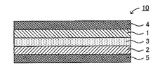
- FIG. 2 is a schematic cross-sectional view showing an example of the solid secondary battery according to the present embodiment.
- the solid secondary battery 10 includes a positive electrode active material layer 1, a negative electrode active material layer 2, and a solid electrolyte layer 3 formed between the positive electrode active material layer 1 and the negative electrode active material layer 2. And a positive electrode current collector 4 for collecting current of the positive electrode active material layer 1 and a negative electrode current collector 5 for collecting current of the negative electrode active material layer 2.
- FIG. 3 is a schematic diagram showing an example of the solid secondary battery system of the present embodiment.
- the solid secondary battery system 20 includes a solid secondary battery 10, an overdischarge processing unit 11, and switches 12 a and 12 b.
- the overdischarge processing unit 11 performs an overdischarge process for bringing the solid secondary battery 10 into an overdischarged state. Specifically, the overdischarge processing unit 11 performs at least one of overdischarge and external short circuit on the solid secondary battery 10.
- the overdischarge processing unit 11 is configured by a circuit having at least a resistance, and short-circuits the solid secondary battery 10 to the outside.
- the overdischarge processing unit 11 is configured by a discharge device (charge / discharge device), and discharges the voltage of the solid secondary battery 10 to, for example, 0V.
- the overdischarge processing unit 11 discharges so that the solid secondary battery 10 is inverted (voltage becomes negative).
- the “external short-circuit” means that the positive electrode active material layer 1 and the negative electrode active material layer 2 are short-circuited (short-circuited) through an external circuit.
- the “overdischarge state” means a state where the voltage of the solid secondary battery 10 is equal to or lower than the rated voltage. For example, a state in which the voltage of the solid secondary battery 10 is approximately 0 V or a state in which the SOC of the solid secondary battery 10 is approximately 0% corresponds to an “overdischarge state”.
- the term “overdischarge treatment” includes an external short circuit using a resistor or the like and an overdischarge by a discharge device or the like.
- the switches 12a and 12b are controlled by the ECU 60 described above.
- the switch unit 12a When the switch unit 12a is on and the switch unit 12b is off, the motor generator MG, the auxiliary machine, and the like in the hybrid vehicle 100 are operated by the power of the solid secondary battery 10.
- the overdischarge processing unit 11 performs overdischarge processing. That is, at least one of overdischarge and external short circuit is performed on the solid secondary battery 10.
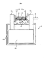
- FIG. 4 corresponds to a schematic cross-sectional view of the solid secondary battery system 20a.
- the solid secondary battery system 20 a includes the solid secondary battery 10, fixing metal plates 31 a and 31 b, a piezoelectric element 32, a resistor coil 33, and a conductive wire 34.
- the solid secondary battery 10 includes an electrode body 10a, a battery case 10b, and a terminal 10c.
- the electrode body 10a includes the positive electrode active material layer 1, the negative electrode active material layer 2, the solid electrolyte layer 3, the positive electrode current collector 4, and the negative electrode current collector 5.
- the terminal 10c is provided with the temperature sensor 40 described above.
- the fixing metal plate 31a is connected to the terminal 10c, and the fixing metal plate 31b is positioned away from the terminal 10c in a state where no voltage is applied to the piezoelectric element 32.
- the piezoelectric element 32 is applied with a voltage from the conductive wire 34, and extends in the direction of the arrow A1 when the voltage is applied.
- the resistor coil 33 is connected to the two terminals 10c via the fixing metal plates 31a and 31b. This state corresponds to a state in which the solid secondary battery 10 is externally short-circuited.
- the fixing metal plates 31a and 31b and the piezoelectric element 32 correspond to the switch 12b described above, and the resistor coil 33 corresponds to the overdischarge processing unit 11 described above.
- the ECU 60 performs control to apply a voltage to the piezoelectric element 32 via the conductive wire 34, thereby causing the solid secondary battery 10 to be externally short-circuited (that is, performing an overdischarge process).
- the internal resistance can be reduced and the output characteristics can be recovered. Therefore, the lifetime of the solid secondary battery 10 can be extended. Conventionally, since it is known that battery performance deteriorates due to overdischarge, an ordinary solid secondary battery is provided with overdischarge protection means for preventing overdischarge. On the other hand, in the present embodiment, the internal resistance can be reduced and the output characteristics can be recovered by actively performing the overdischarge treatment on the solid secondary battery 10 that has deteriorated in cycle.
- the mechanism by which the internal resistance can be reduced by overdischarge treatment is presumed as follows.
- SEI Solid Electrolyte Interphase
- this film can be removed and internal resistance can be reduced by performing an overdischarge treatment.
- this film may be generated at an arbitrary solid / solid interface in the solid secondary battery 10, but it is considered that this film is often generated particularly at the interface between the active material and the solid electrolyte material.
- the active material undergoes an active reaction of occluding and releasing metal ions on the surface thereof, and the solid electrolyte material usually has a large area in contact with the active material.
- a coating tends to be formed when the active material and the solid electrolyte material are combinations derived from different types of compounds.
- an oxide active material derived from an oxide
- a sulfide solid electrolyte material derived from a sulfide
- ⁇ Control method> a control method performed by the ECU 60 in the present embodiment will be described.
- the ECU 60 when the battery temperature of the solid secondary battery 10 is equal to or higher than a predetermined temperature, the ECU 60 does not charge the solid secondary battery 10 before charging the solid secondary battery 10 (hereinafter simply referred to as “battery”).
- the voltage is also expressed as “Voltage”). That is, when the battery temperature is equal to or higher than the predetermined temperature, the ECU 60 performs charging after performing an overdischarge process. Conversely, when the battery temperature is lower than the predetermined temperature, the ECU 60 quickly charges the solid secondary battery 10 without performing the overdischarge process.
- the ECU 60 when the battery temperature is equal to or higher than a predetermined temperature, the ECU 60 performs control to keep the battery voltage below the rated voltage before charging the solid secondary battery 10. For example, the ECU 60 holds the battery voltage at 0V. In this case, the ECU 60 continues the control to keep the battery voltage below the rated voltage for the time corresponding to the battery temperature. That is, the ECU 60 changes the time for holding the battery voltage below the rated voltage (hereinafter referred to as “holding time”) according to the battery temperature. Specifically, the ECU 60 shortens the holding time when the battery temperature is high compared to when the battery temperature is low.
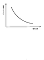
- FIG. 5 is a diagram schematically showing the relationship between the battery temperature and the refresh time.
- the “refresh time” corresponds to the time (holding time) required for the resistance of the solid secondary battery 10 to fall below a predetermined value by holding the battery voltage below the rated voltage (for example, 0 V).
- the relationship between the battery temperature and the refresh time as shown in FIG. 5 can be obtained, for example, by conducting experiments using various battery temperatures and various holding times.
- FIG. 5 shows that the higher the battery temperature, the shorter the refresh time (in other words, the lower the battery temperature, the longer the refresh time). This is presumed to be because the higher the battery temperature, the faster the removal rate of the coating (SEI) of the solid secondary battery 10 and the lower the internal resistance earlier. Thus, in a state where the internal resistance is reduced, the output characteristics are restored, and the solid secondary battery 10 can be charged efficiently.
- SEI the removal rate of the coating
- the overdischarge process and the charging are controlled in consideration of the relationship between the battery temperature and the refresh time.
- the ECU 60 reduces the internal resistance of the solid secondary battery 10 to a predetermined value or less only when the battery temperature is such that the refresh time is non-drivingly short, that is, by overdischarge processing.
- Control is performed to keep the battery voltage below the rated voltage before charging the solid secondary battery 10 only when the battery temperature is such that the time required until the time is short. Thereby, it can suppress that it takes a long time to recover the output characteristics of the solid secondary battery 10. That is, the output characteristics of the solid secondary battery 10 can be recovered early. And it becomes possible to charge the solid secondary battery 10 efficiently by charging with respect to the solid secondary battery 10 in the state in which the output characteristic was recovered.
- control is performed to hold the battery voltage below the rated voltage for the holding time corresponding to the relationship between the battery temperature and the refresh time as shown in FIG.
- a holding time to be used for the battery temperature is determined in advance in the map, and the ECU 60 refers to such a map so that the current battery can be used.
- a holding time corresponding to the temperature is acquired, and control is performed to hold the battery voltage below the rated voltage. By doing so, it becomes possible to more efficiently recover and charge the output characteristics of the solid secondary battery 10.
- the refresh time can be used as the holding time, and in another example, a time slightly longer or slightly shorter than the refresh time can be used as the holding time.
- control flow is repeatedly executed by the ECU 60 at a predetermined cycle.
- step S101 the ECU 60 determines whether or not the solid secondary battery 10 is in a chargeable state. For example, when the solid secondary battery 10 is in a fully charged state or the like, the ECU 60 determines that the solid secondary battery 10 is not in a chargeable state.
- step S101 If the solid secondary battery 10 is in a chargeable state (step S101; Yes), the process proceeds to step S102. If the solid secondary battery 10 is not in a chargeable state (step S101; No), the process ends. . In step S102, the ECU 60 acquires the temperature (battery temperature) of the solid secondary battery 10 detected by the temperature sensor 40. Then, the process proceeds to step S103.
- the ECU 60 determines whether or not the battery temperature is equal to or higher than a predetermined temperature.
- the ECU 60 determines whether or not the battery temperature is such that the refresh time is non-trivially short, in other words, the time required to reduce the internal resistance of the solid secondary battery 10 to a predetermined value or less by the overdischarge process. It is determined whether or not the battery temperature is such that it is drastically short.
- the predetermined temperature is determined based on a battery temperature corresponding to a refresh time equal to or shorter than a predetermined time, which is determined from the relationship shown in FIG.
- the predetermined temperature is determined based on a battery temperature assumed after power use of the solid secondary battery 10 in consideration of the tendency of the solid secondary battery 10 to be charged after power use. The Preferably, 30 ° C. is used as the predetermined temperature.
- step S103 If the battery temperature is equal to or higher than the predetermined temperature (step S103; Yes), the process proceeds to step S104. On the other hand, when the battery temperature is lower than the predetermined temperature (step S103; No), the process proceeds to step S107. In this case, the ECU 60 starts charging the solid secondary battery 10 without performing control to keep the battery voltage below the rated voltage (that is, without performing overdischarge processing) (step S107). Then, the process ends.
- step S104 the ECU 60 refers to the map in which the battery voltage and the holding time are associated with each other, and acquires the holding time corresponding to the battery temperature acquired in step S102. Then, the process proceeds to step S105.
- step S105 the ECU 60 performs control to keep the battery voltage below the rated voltage. Preferably, the ECU 60 performs control to keep the battery voltage at 0V. In one example, when the overdischarge processing unit 11 performs an external short circuit, the ECU 60 performs control to maintain the external short circuit state of the solid secondary battery 10. In another example, when the overdischarge processing unit 11 is a discharge device, the ECU 60 performs control to continue constant voltage discharge (CV discharge) so that the battery voltage is maintained at 0V. Then, the process proceeds to step S106. When the battery voltage is high to some extent at the start of the process of step S105, control may be performed to hold the battery voltage at 0 V after temporarily reducing the battery voltage by overdischarge using a discharge device or the like.
- CV discharge constant voltage discharge
- step S106 the ECU 60 determines whether or not the holding time acquired in step S104 has elapsed. If the holding time has not elapsed (step S106; No), the process returns to step S105, and the ECU 60 continues the control to hold the battery voltage below the rated voltage. On the other hand, when the holding time has elapsed (step S106; Yes), the ECU 60 ends the control to hold the battery voltage below the rated voltage and starts charging the solid secondary battery 10 (step S107). ). Then, the process ends.
- FIG. 6 shows an example in which after the holding time corresponding to the battery temperature is acquired, the holding voltage is not changed (that is, the holding time is fixed), and control is performed to hold the battery voltage below the rated voltage. .
- the holding voltage is not changed (that is, the holding time is fixed), and control is performed to hold the battery voltage below the rated voltage.
- the output characteristics can be recovered and charged more efficiently.
- the battery voltage is held at 0V, but the battery voltage is not limited to being held at 0V as long as the voltage is equal to or lower than the rated voltage determined for each battery.
- control to hold the battery voltage after lowering the battery voltage below the rated voltage has been shown, but control to lower the battery voltage below the rated voltage without performing control to hold the battery voltage It is also good to do only. For example, only control for reducing the battery voltage to 0 V can be performed.
- the temperature (battery temperature) of the solid secondary battery 10 is directly detected by the temperature sensor 40.
- the battery temperature may be indirectly detected. Specifically, a value representative of the battery temperature may be detected.
- the battery temperature may be estimated based on a predetermined arithmetic expression, a map, or the like instead of being detected by the sensor.
- Example 1 Synthesis of sulfide solid electrolyte materials
- lithium sulfide Li 2 S, manufactured by Nippon Chemical Industry Co., Ltd.
- diphosphorus pentasulfide P 2 S 5 , manufactured by Aldrich
- Li 2 S and P 2 S 5 have a molar ratio of 75Li 2 S ⁇ 25P 2 S 5 (Li 3 PS 4 , ortho composition). Weighed as follows. 2 g of this mixture was mixed for 5 minutes in an agate mortar.
- the solid electrolyte may be an oxide, nitride, or halide, and any of crystal, amorphous, and glass ceramics can be used.
- LiNi 1/3 Co 1/3 Mn 1/3 O 2 positive electrode active material, manufactured by Nichia Corporation 12.03 mg, VGCF (vapor-grown carbon fiber, conductive material, manufactured by Showa Denko KK) 51 mg, 5.03 mg of the above-mentioned sulfide solid electrolyte material was weighed, and these were mixed to obtain a positive electrode mixture. Further, 9.06 mg of graphite (negative electrode active material, manufactured by Mitsubishi Chemical Corporation) and 8.24 mg of the above sulfide solid electrolyte material were weighed and mixed to obtain a negative electrode mixture.
- a solid secondary battery was obtained using a 15 ⁇ m Al foil (manufactured by Nippon Foil Co., Ltd.) as the positive electrode current collector and a 10 ⁇ m Cu foil (manufactured by Nippon Foil Co., Ltd.) as the negative electrode current collector.
- the positive electrode is an active material that can be used for a Li-ion battery
- a layered positive electrode active material such as LiCoO 2 or LiNiO 2 , an olivine-type positive electrode active material, a spinel-type positive electrode active material, or the like can also be used.
- a carbon material or a metal material can be used as the conductive auxiliary agent for the positive electrode.
- the negative electrode is an active material that can be used for a Li-ion battery, there is no limitation to using the above-described materials.
- the current collector is not limited to using the foil as described above.
- the current value for performing CC discharge is not limited to the above. However, if the current value is small, CC discharge takes time, and if the current value is large, the overvoltage becomes large. Therefore, it is preferably in the range of 0.1 mAh to 10 mAh, for example.
- Example 2 In Example 2, 60 minutes was hold
- Example 3 In Example 3, 240 min was held at 40 ° C. in the overdischarge treatment. Except this, it is the same as the first embodiment.
- Example 4 In Example 4, 450 minutes was hold
- Comparative Example 1 In Comparative Example 1, the overdischarge treatment was held at 25 ° C. for 15 minutes. Except this, it is the same as the first embodiment.
- Comparative Example 2 In Comparative Example 2, the overdischarge treatment was held at 25 ° C. for 600 minutes. Except this, it is the same as the first embodiment.
- FIG. 7 shows an example of the results of Examples 1 to 4 and Comparative Examples 1 and 2 described above.
- FIG. 7 shows that in Examples 1 to 4 and Comparative Example 2, the resistance of the solid secondary battery is appropriately reduced. This is presumably because Examples 1 to 4 and Comparative Example 2 were held for an appropriate time according to the battery temperature.
- the comparative example 1 it turns out that the resistance of a solid secondary battery has not decreased so much. This is probably because Comparative Example 1 did not hold for an appropriate time according to the battery temperature. Specifically, it is considered that the holding time is too short.
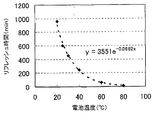
- FIG. 8 shows an example of the relationship between the battery temperature and the refresh time. Such a relationship is obtained by conducting experiments using various battery temperatures and various holding times. From FIG. 8, it was confirmed that the refresh time becomes shorter as the battery temperature becomes higher. In other words, it was confirmed that the refresh time becomes longer as the battery temperature becomes lower. Based on such a result, the holding time used for the aforementioned control is determined.
- the present invention can be used to charge a solid secondary battery.
Landscapes
- Chemical & Material Sciences (AREA)
- Engineering & Computer Science (AREA)
- Manufacturing & Machinery (AREA)
- Chemical Kinetics & Catalysis (AREA)
- Electrochemistry (AREA)
- General Chemical & Material Sciences (AREA)
- Physics & Mathematics (AREA)
- Condensed Matter Physics & Semiconductors (AREA)
- General Physics & Mathematics (AREA)
- Inorganic Chemistry (AREA)
- Secondary Cells (AREA)
Abstract
Priority Applications (3)
| Application Number | Priority Date | Filing Date | Title |
|---|---|---|---|
| JP2013519330A JP5679055B2 (ja) | 2011-06-10 | 2011-06-10 | 電池の充電方法、及び電池の充電制御装置 |
| US14/123,233 US9240694B2 (en) | 2011-06-10 | 2011-06-10 | Method for charging battery and charge control device for battery |
| PCT/JP2011/063368 WO2012169066A1 (fr) | 2011-06-10 | 2011-06-10 | Procédé pour charger une batterie et appareil pour contrôler la charge d'une batterie |
Applications Claiming Priority (1)
| Application Number | Priority Date | Filing Date | Title |
|---|---|---|---|
| PCT/JP2011/063368 WO2012169066A1 (fr) | 2011-06-10 | 2011-06-10 | Procédé pour charger une batterie et appareil pour contrôler la charge d'une batterie |
Publications (1)
| Publication Number | Publication Date |
|---|---|
| WO2012169066A1 true WO2012169066A1 (fr) | 2012-12-13 |
Family
ID=47295667
Family Applications (1)
| Application Number | Title | Priority Date | Filing Date |
|---|---|---|---|
| PCT/JP2011/063368 Ceased WO2012169066A1 (fr) | 2011-06-10 | 2011-06-10 | Procédé pour charger une batterie et appareil pour contrôler la charge d'une batterie |
Country Status (3)
| Country | Link |
|---|---|
| US (1) | US9240694B2 (fr) |
| JP (1) | JP5679055B2 (fr) |
| WO (1) | WO2012169066A1 (fr) |
Cited By (5)
| Publication number | Priority date | Publication date | Assignee | Title |
|---|---|---|---|---|
| EP2946433A4 (fr) * | 2013-01-16 | 2016-08-24 | Bathium Canada Inc | Cellule électrochimique ou batterie ayant une impédance réduite et procédé de production de celle-ci |
| WO2018074021A1 (fr) * | 2016-10-18 | 2018-04-26 | 株式会社村田製作所 | Dispositif de charge-décharge, procédé de charge-décharge, dispositif électronique, véhicule électrique et système d'alimentation |
| CN110720151A (zh) * | 2018-01-12 | 2020-01-21 | 株式会社Lg化学 | 二次电池的充电-放电装置以及包括该充电-放电装置的二次电池的激活处理装置 |
| JP2020087658A (ja) * | 2018-11-22 | 2020-06-04 | トヨタ自動車株式会社 | 全固体二次電池の製造方法 |
| JP2024075435A (ja) * | 2022-11-22 | 2024-06-03 | トヨタ自動車株式会社 | 固体電池及び固体電池の製造方法 |
Families Citing this family (4)
| Publication number | Priority date | Publication date | Assignee | Title |
|---|---|---|---|---|
| JP6779505B2 (ja) * | 2015-12-18 | 2020-11-04 | 昭和電工株式会社 | セロオリゴ糖の製造方法 |
| JP7284923B2 (ja) | 2021-04-09 | 2023-06-01 | 株式会社安川電機 | エンコーダ、サーボモータ、サーボシステム |
| CN114267891B (zh) * | 2021-05-19 | 2024-04-19 | 江苏申港锅炉有限公司 | 抑制锂枝晶生长的全固态锂电池充电温度控制方法及系统 |
| CN116936971B (zh) * | 2023-09-15 | 2024-01-05 | 中石油深圳新能源研究院有限公司 | 一种全固态锂电池充电温度控制方法 |
Citations (3)
| Publication number | Priority date | Publication date | Assignee | Title |
|---|---|---|---|---|
| JPH04137371A (ja) * | 1990-09-26 | 1992-05-12 | Sony Corp | 二次電池の保護装置 |
| JPH10224998A (ja) * | 1997-02-10 | 1998-08-21 | Nissan Motor Co Ltd | 2次電池の保護装置 |
| JP2000113909A (ja) * | 1998-08-04 | 2000-04-21 | Furukawa Battery Co Ltd:The | リチウム二次電池の保管方法 |
Family Cites Families (8)
| Publication number | Priority date | Publication date | Assignee | Title |
|---|---|---|---|---|
| JP2001076764A (ja) * | 1999-09-07 | 2001-03-23 | Tokyo R & D Co Ltd | 時計手段を有する電動装置 |
| JP4240722B2 (ja) * | 2000-01-27 | 2009-03-18 | 三洋電機株式会社 | 電池の満充電表示方法 |
| JP3857146B2 (ja) * | 2002-01-16 | 2006-12-13 | 本田技研工業株式会社 | ハイブリッド車両の制御装置 |
| KR100672799B1 (ko) * | 2002-07-12 | 2007-01-24 | 가부시키가이샤 리코 | 가열 장치, 보조 전력 공급 장치, 보조 전력 공급 시스템,정착 장치 및 화상 형성 장치 |
| JP5020546B2 (ja) * | 2006-06-01 | 2012-09-05 | 株式会社リコー | 充放電保護回路、該充放電保護回路を組み込んだバッテリーパック、該バッテリーパックを用いた電子機器、携帯ゲーム機 |
| JP2010225582A (ja) | 2009-02-24 | 2010-10-07 | Idemitsu Kosan Co Ltd | 電動装置 |
| JP5419743B2 (ja) | 2009-02-24 | 2014-02-19 | 出光興産株式会社 | 電動装置及び電動装置の使用方法 |
| JP5508646B2 (ja) | 2011-05-27 | 2014-06-04 | トヨタ自動車株式会社 | 固体二次電池システムおよび再生固体二次電池の製造方法 |
-
2011
- 2011-06-10 US US14/123,233 patent/US9240694B2/en active Active
- 2011-06-10 JP JP2013519330A patent/JP5679055B2/ja active Active
- 2011-06-10 WO PCT/JP2011/063368 patent/WO2012169066A1/fr not_active Ceased
Patent Citations (3)
| Publication number | Priority date | Publication date | Assignee | Title |
|---|---|---|---|---|
| JPH04137371A (ja) * | 1990-09-26 | 1992-05-12 | Sony Corp | 二次電池の保護装置 |
| JPH10224998A (ja) * | 1997-02-10 | 1998-08-21 | Nissan Motor Co Ltd | 2次電池の保護装置 |
| JP2000113909A (ja) * | 1998-08-04 | 2000-04-21 | Furukawa Battery Co Ltd:The | リチウム二次電池の保管方法 |
Cited By (7)
| Publication number | Priority date | Publication date | Assignee | Title |
|---|---|---|---|---|
| EP2946433A4 (fr) * | 2013-01-16 | 2016-08-24 | Bathium Canada Inc | Cellule électrochimique ou batterie ayant une impédance réduite et procédé de production de celle-ci |
| WO2018074021A1 (fr) * | 2016-10-18 | 2018-04-26 | 株式会社村田製作所 | Dispositif de charge-décharge, procédé de charge-décharge, dispositif électronique, véhicule électrique et système d'alimentation |
| CN110720151A (zh) * | 2018-01-12 | 2020-01-21 | 株式会社Lg化学 | 二次电池的充电-放电装置以及包括该充电-放电装置的二次电池的激活处理装置 |
| JP2020087658A (ja) * | 2018-11-22 | 2020-06-04 | トヨタ自動車株式会社 | 全固体二次電池の製造方法 |
| JP7017137B2 (ja) | 2018-11-22 | 2022-02-08 | トヨタ自動車株式会社 | 全固体二次電池の製造方法 |
| JP2024075435A (ja) * | 2022-11-22 | 2024-06-03 | トヨタ自動車株式会社 | 固体電池及び固体電池の製造方法 |
| JP7794727B2 (ja) | 2022-11-22 | 2026-01-06 | トヨタ自動車株式会社 | 固体電池及び固体電池の製造方法 |
Also Published As
| Publication number | Publication date |
|---|---|
| JP5679055B2 (ja) | 2015-03-04 |
| US9240694B2 (en) | 2016-01-19 |
| JPWO2012169066A1 (ja) | 2015-02-23 |
| US20140097800A1 (en) | 2014-04-10 |
Similar Documents
| Publication | Publication Date | Title |
|---|---|---|
| JP5679055B2 (ja) | 電池の充電方法、及び電池の充電制御装置 | |
| JP6123642B2 (ja) | 全固体電池の充電システム | |
| CN103563160B (zh) | 固体二次电池系统及可再生固体二次电池的制造方法 | |
| JP5673826B2 (ja) | リチウム固体二次電池システム | |
| JP6347254B2 (ja) | 蓄電装置、蓄電システムおよび電動車両 | |
| JP5637309B2 (ja) | 固体二次電池システム | |
| US20210152010A1 (en) | Method for charging battery and charging system | |
| JP5900244B2 (ja) | 固体電池の製造方法 | |
| US11183706B2 (en) | Lithium-ion second battery controller for reducing charging loss while preventing deterioration from lithium deposition | |
| JP6879136B2 (ja) | 二次電池の充放電制御装置 | |
| JP2019106285A (ja) | 二次電池システムおよび二次電池の活物質の応力推定方法 | |
| WO2016080128A1 (fr) | Pile au lithium-ion | |
| JP7131002B2 (ja) | 二次電池の劣化推定装置 | |
| US20210152001A1 (en) | Method for charging battery and charging system | |
| US9735454B2 (en) | Apparatus for controlling lithium-ion battery and method of recovering lithium-ion battery | |
| CN111551861B (zh) | 电池系统和二次电池的soc估计方法 | |
| KR101833964B1 (ko) | 배터리 셀용 진성 과충전 보호 | |
| JP2012257367A (ja) | 電池の制御装置 | |
| JP2020114066A (ja) | 二次電池の充放電制御装置 | |
| JP2008199767A (ja) | 電池パックの制御装置 | |
| JP5664460B2 (ja) | 固体二次電池システム | |
| CN107636884A (zh) | 用于运行可充电的电池组电池的方法和电池组控制设备 | |
| JP7020177B2 (ja) | 電池システム | |
| JP2019220260A (ja) | 電池システム | |
| JP2018006239A (ja) | 電池システム |
Legal Events
| Date | Code | Title | Description |
|---|---|---|---|
| 121 | Ep: the epo has been informed by wipo that ep was designated in this application |
Ref document number: 11867460 Country of ref document: EP Kind code of ref document: A1 |
|
| ENP | Entry into the national phase |
Ref document number: 2013519330 Country of ref document: JP Kind code of ref document: A |
|
| WWE | Wipo information: entry into national phase |
Ref document number: 14123233 Country of ref document: US |
|
| NENP | Non-entry into the national phase |
Ref country code: DE |
|
| 122 | Ep: pct application non-entry in european phase |
Ref document number: 11867460 Country of ref document: EP Kind code of ref document: A1 |