WO2012169091A1 - Dispositif d'aiguille à demeure - Google Patents
Dispositif d'aiguille à demeure Download PDFInfo
- Publication number
- WO2012169091A1 WO2012169091A1 PCT/JP2011/077935 JP2011077935W WO2012169091A1 WO 2012169091 A1 WO2012169091 A1 WO 2012169091A1 JP 2011077935 W JP2011077935 W JP 2011077935W WO 2012169091 A1 WO2012169091 A1 WO 2012169091A1
- Authority
- WO
- WIPO (PCT)
- Prior art keywords
- shield
- pair
- tube
- hub
- stopper
- Prior art date
- Legal status (The legal status is an assumption and is not a legal conclusion. Google has not performed a legal analysis and makes no representation as to the accuracy of the status listed.)
- Ceased
Links
Images









Classifications
-
- A—HUMAN NECESSITIES
- A61—MEDICAL OR VETERINARY SCIENCE; HYGIENE
- A61M—DEVICES FOR INTRODUCING MEDIA INTO, OR ONTO, THE BODY; DEVICES FOR TRANSDUCING BODY MEDIA OR FOR TAKING MEDIA FROM THE BODY; DEVICES FOR PRODUCING OR ENDING SLEEP OR STUPOR
- A61M5/00—Devices for bringing media into the body in a subcutaneous, intra-vascular or intramuscular way; Accessories therefor, e.g. filling or cleaning devices, arm-rests
- A61M5/14—Infusion devices, e.g. infusing by gravity; Blood infusion; Accessories therefor
- A61M5/158—Needles for infusions; Accessories therefor, e.g. for inserting infusion needles, or for holding them on the body
-
- A—HUMAN NECESSITIES
- A61—MEDICAL OR VETERINARY SCIENCE; HYGIENE
- A61M—DEVICES FOR INTRODUCING MEDIA INTO, OR ONTO, THE BODY; DEVICES FOR TRANSDUCING BODY MEDIA OR FOR TAKING MEDIA FROM THE BODY; DEVICES FOR PRODUCING OR ENDING SLEEP OR STUPOR
- A61M25/00—Catheters; Hollow probes
- A61M25/01—Introducing, guiding, advancing, emplacing or holding catheters
- A61M25/06—Body-piercing guide needles or the like
- A61M25/0606—"Over-the-needle" catheter assemblies, e.g. I.V. catheters
-
- A—HUMAN NECESSITIES
- A61—MEDICAL OR VETERINARY SCIENCE; HYGIENE
- A61M—DEVICES FOR INTRODUCING MEDIA INTO, OR ONTO, THE BODY; DEVICES FOR TRANSDUCING BODY MEDIA OR FOR TAKING MEDIA FROM THE BODY; DEVICES FOR PRODUCING OR ENDING SLEEP OR STUPOR
- A61M25/00—Catheters; Hollow probes
- A61M25/01—Introducing, guiding, advancing, emplacing or holding catheters
- A61M25/06—Body-piercing guide needles or the like
- A61M25/0612—Devices for protecting the needle; Devices to help insertion of the needle, e.g. wings or holders
- A61M25/0631—Devices for protecting the needle; Devices to help insertion of the needle, e.g. wings or holders having means for fully covering the needle after its withdrawal, e.g. needle being withdrawn inside the handle or a cover being advanced over the needle
-
- A—HUMAN NECESSITIES
- A61—MEDICAL OR VETERINARY SCIENCE; HYGIENE
- A61M—DEVICES FOR INTRODUCING MEDIA INTO, OR ONTO, THE BODY; DEVICES FOR TRANSDUCING BODY MEDIA OR FOR TAKING MEDIA FROM THE BODY; DEVICES FOR PRODUCING OR ENDING SLEEP OR STUPOR
- A61M5/00—Devices for bringing media into the body in a subcutaneous, intra-vascular or intramuscular way; Accessories therefor, e.g. filling or cleaning devices, arm-rests
- A61M5/14—Infusion devices, e.g. infusing by gravity; Blood infusion; Accessories therefor
- A61M5/158—Needles for infusions; Accessories therefor, e.g. for inserting infusion needles, or for holding them on the body
- A61M2005/1587—Needles for infusions; Accessories therefor, e.g. for inserting infusion needles, or for holding them on the body suitable for being connected to an infusion line after insertion into a patient
-
- A—HUMAN NECESSITIES
- A61—MEDICAL OR VETERINARY SCIENCE; HYGIENE
- A61M—DEVICES FOR INTRODUCING MEDIA INTO, OR ONTO, THE BODY; DEVICES FOR TRANSDUCING BODY MEDIA OR FOR TAKING MEDIA FROM THE BODY; DEVICES FOR PRODUCING OR ENDING SLEEP OR STUPOR
- A61M25/00—Catheters; Hollow probes
- A61M25/01—Introducing, guiding, advancing, emplacing or holding catheters
- A61M25/06—Body-piercing guide needles or the like
- A61M25/0612—Devices for protecting the needle; Devices to help insertion of the needle, e.g. wings or holders
- A61M25/0637—Butterfly or winged devices, e.g. for facilitating handling or for attachment to the skin
Definitions
- the present invention includes a soft outer needle and a hard inner needle, and can puncture a patient with the tip of the inner needle protruding from the tip of the outer needle, and then the inner needle can be retracted from the outer needle. It is related with the indwelling needle apparatus comprised as follows.
- Indwelling needle devices are widely used for treatments such as infusion, blood transfusion, and extracorporeal blood circulation.
- a metal needle is left in the blood vessel, the blood vessel may be damaged. Therefore, an indwelling needle device having a soft outer needle and a hard inner needle is known. With the tip of the inner needle protruding from the tip of the outer needle, the outer needle and the inner needle are punctured into the patient's blood vessel, and then the inner needle is retracted from the outer needle and only the outer needle is left in the patient. The indwelling soft outer needle is unlikely to damage the patient's blood vessels.
- FIG. 18A is a perspective view of an example of such a conventional indwelling needle device 900 (see, for example, Patent Document 1) as viewed from above
- FIG. 18B is a perspective view as viewed from below
- FIG. It is arrow sectional drawing of the conventional indwelling needle apparatus 900 along the vertical surface containing 19 lines.
- the side where the patient is punctured (the left side of the paper surface in FIGS. 18A, 18B and 19) is called “front side”, and the opposite side is called “rear side”.
- the indwelling needle device 900 includes a shield 920 including a shield cylinder 921 having a substantially cylindrical shape and an outer hub 925 fixed to one end (front end) thereof.
- a soft outer needle 930 is fixed to the front end of the outer hub 925.
- a pair of blades 929a and 929b are provided on the outer peripheral surface of the shield tube 921 near the outer hub 925 side end.
- the wings 929a and 929b have flexibility and can swing up and down.
- a hub 940 is inserted into the lumen of the shield 920 so as to be movable in the longitudinal direction of the shield 920 (that is, the front-rear direction).
- a metal hard inner needle 950 is fixed to the front end of the hub 940, and one end of a flexible tube 960 is connected to the rear end of the hub 940.
- the inner needle 950 and the tube 960 communicate with each other via a longitudinal passage 943 that penetrates the hub 940 in the front-rear direction.
- the hub 940 is located on the front end side of the lumen of the shield 920. This position of the hub 940 relative to the shield 920 is referred to as the “initial position”. In the initial position, the inner needle 950 held by the hub 940 passes through the outer needle 930, and the tip of the inner needle 950 protrudes from the tip of the outer needle 930 to the outside.
- FIG. 20 is a perspective view of the stopper 970.
- a substantially semi-cylindrical insertion portion 972 and a pair of fixing portions 973 extend from a substantially semi-cylindrical base end portion 971.
- the insertion portion 972 is disposed between the pair of fixing portions 973 and these are parallel to each other.
- the insertion portion 972 of the stopper 970 is inserted from the rear end of the shield tube 921.
- the hub 940 can be disposed at the initial position.
- a part of the tube 960 is exposed on the lower surface side of the base end portion 971 of the stopper 970.
- the inner needle 950 and the outer needle 930 are punctured into the patient's blood vessel while holding the hub 940 in the initial position.
- the operator may hold the base end 971 of the stopper 970 vertically (see arrow H91 in FIG. 18A) or horizontally (see arrow H92 in FIG. 18A) with two fingers.
- the pair of fixing portions 973 may be gripped in the horizontal direction (see arrow H93 in FIG. 18A).
- the pair of wings 929a and 929b are folded upward so that the pair of fixing portions 973 are sandwiched and fixed between the pair of wings 929a and 929b and the shield tube 921, and the pair of wings 929a and 929b overlapped with each other. You may hold
- the stopper 970 is removed from the shield 920, and then the tube 960 is pulled from the shield 920.
- the hub 940 and the inner needle 950 together with the tube 960 move backward with respect to the shield 920, and the inner needle 950 is housed in the shield 920 as shown in FIG.
- the position of the hub 940 with respect to the shield 920 shown in FIG. In this state, the indwelling needle device 910 is fixed to the patient using an adhesive tape or the like. Only the soft outer needle 930 is placed while being punctured by the patient.
- the conventional indwelling needle device 900 requires an operation of pulling the tube 960 with respect to the shield 920 in order to store the inner needle 950 in the shield 920 as shown in FIG. Prior to or simultaneously with this operation, it is necessary to remove (remove) the stopper 970 from the shield 920.
- the stopper 970 only has a function of maintaining the hub 940 in the initial position when puncturing, and the inner needle 950 cannot be retracted only by removing the stopper 970.
- the first object of the present invention is to reduce the possibility of an erroneous operation of forgetting to remove only the stopper after puncture and store the inner needle in the shield.
- the second object of the present invention is to reduce the necessity of changing the gripping position between puncturing and storing the inner needle in a shield.
- the indwelling needle device of the present invention includes a shield having a lumen, a soft outer needle fixed to the front end of the shield, and a hub that is disposed in the lumen of the shield and is movable in the longitudinal direction of the shield. And a rigid inner needle fixed to the front end of the hub, a tube connected to the rear end of the hub, and a stopper inserted into and removed from the rear end of the shield. An initial position in which the hub is located on the front end side of the lumen of the shield and the inner needle penetrates the outer needle and protrudes from the tip of the outer needle; and the hub is located behind the lumen of the shield.
- the hub is displaced to a retracted position which is located on the end side and the inner needle is housed in the lumen of the shield.
- the stopper includes an insertion portion that is inserted into the lumen of the shield, and a base portion that is provided at a rear end of the insertion portion.
- the base portion is located outside the shield.
- the base portion exposes a part of the outer peripheral surface of the tube and covers a roof portion, and a pair of holding portions that are arranged to sandwich the tube and can be elastically displaced so as to grip the tube.
- the tube can be pulled together with the stopper by grasping the base portion and removing the stopper from the shield after puncturing the indwelling needle device. . Therefore, it is possible to reduce the possibility of an erroneous operation of forgetting to remove only the stopper and store the inner needle in the shield.
- the inner needle when the indwelling needle device is punctured while holding the base, the inner needle can be stored in the shield without changing the holding position thereafter. Therefore, a series of operations when using the indwelling needle device can be performed quickly and efficiently.
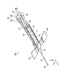
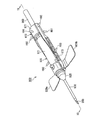
- FIG. 1A is a perspective view of an indwelling needle device according to Embodiment 1 of the present invention as viewed from above.
- FIG. 1B is a perspective view of the indwelling needle device according to the first embodiment of the present invention as viewed from below.
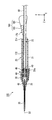
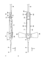
- FIG. 2 is a cross-sectional view of the indwelling needle device according to the first embodiment of the present invention along the vertical plane including line 2-2 in FIG. 1A.
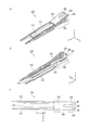
- 3A is a perspective view of the hub used in the indwelling needle device according to the first embodiment of the present invention
- FIG. 3B is a cross-sectional view of the hub along the plane including the line 3B-3B in FIG. 3A, and FIG. FIG.
- FIG. 3B is a cross-sectional view of the hub taken along the plane including the line 3C-3C of 3A.
- 4A is a perspective view seen from above the stopper used in the indwelling needle device according to Embodiment 1 of the present invention
- FIG. 4B is a perspective view seen from below
- FIG. 4C is a plan view thereof.
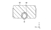
- FIG. 5 is a cross-sectional view of the indwelling needle device according to the first embodiment of the present invention along the vertical plane including line 5-5 in FIG. 1A.
- 6A and 6B are diagrams showing typical gripping positions when puncturing the indwelling needle device according to Embodiment 1 of the present invention
- FIG. 6A is a side view
- FIG. 6B is a plan view.
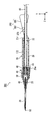
- FIG. 7 is a perspective view seen from above of the indwelling needle device according to the first embodiment of the present invention in which the hub is in the retracted position.
- FIG. 8 is a cross-sectional view of the indwelling needle device according to the first embodiment of the present invention along the vertical plane including line 8-8 in FIG.
- FIG. 9A is a perspective view of the indwelling needle device according to the second embodiment of the present invention as seen from above.
- FIG. 9B is a perspective view of the indwelling needle device according to the second embodiment of the present invention as viewed from below.
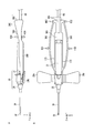
- FIG. 10 is a cross-sectional view of the indwelling needle device according to the second embodiment of the present invention along the vertical plane including the line 10-10 in FIG. 9A.
- FIG. 11A is a perspective view seen from above a stopper used in an indwelling needle device according to Embodiment 2 of the present invention
- FIG. 11B is a perspective view seen from below
- FIG. 11C is a plan view thereof.
- FIG. 12 is a cross-sectional view of the indwelling needle device according to the second embodiment of the present invention along the vertical plane including the line 12-12 in FIG. 9A.
- 13A and 13B are views showing typical gripping positions when puncturing the indwelling needle device according to Embodiment 2 of the present invention
- FIG. 13A is a side view
- FIG. 13B is a plan view.
- FIG. 14A is a perspective view of the indwelling needle device according to the third embodiment of the present invention as seen from above.
- FIG. 14A is a perspective view of the indwelling needle device according to the third embodiment of the present invention as seen from above.
- FIG. 14A is a perspective view of the indwelling needle device according to the
- FIG. 14B is a perspective view of the indwelling needle device according to the third embodiment of the present invention as seen from below.
- FIG. 15 is a cross-sectional view of the indwelling needle device according to the third embodiment of the present invention along the vertical plane including the line 15-15 in FIG. 14A.
- 16A is a perspective view seen from above the stopper used in the indwelling needle device according to Embodiment 3 of the present invention
- FIG. 16B is a perspective view seen from below
- FIG. 16C is a plan view thereof.
- FIGS. 17A and 17B are views showing typical gripping positions when puncturing the indwelling needle device according to Embodiment 3 of the present invention
- FIG. 17A is a side view
- FIG. 17B is a plan view.
- FIG. 18A is a perspective view of a conventional indwelling needle device as viewed from above.
- FIG. 18B is a perspective view of the conventional indwelling needle device as viewed from below.
- FIG. 19 is a cross-sectional view of the conventional indwelling needle device taken along the vertical plane including the line 19-19 in FIG. 18A.
- FIG. 20 is a perspective view of a stopper used in the conventional indwelling needle device shown in FIGS. 18A and 18B.
- 21 is a cross-sectional view of the conventional indwelling needle device shown in FIGS. 18A and 18B along the same plane as FIG. 19 in which the inner needle is housed in the shield.
- a size of the pair of sandwiching portions in a direction in which the pair of sandwiching portions sandwich the tube and a direction perpendicular to the longitudinal direction of the insertion portion is larger than that of the roof portion. Is preferred. Thereby, an indwelling needle apparatus and a stopper can be stably hold
- the roof portion and the pair of sandwiching portions are arranged in this order from the insertion portion side. Therefore, it becomes possible to arrange
- the upper surface of the roof portion is inclined so that the height in the direction in which the pair of sandwiching portions sandwich the tube and the direction perpendicular to the longitudinal direction of the insertion portion becomes lower as approaching the insertion portion. It is preferable. Furthermore, it is preferable that the upper surfaces of the pair of sandwiching portions are similarly inclined. Accordingly, when the indwelling needle device is punctured by grasping the pair of sandwiching portions, the work of removing the stopper from the shield is facilitated thereafter.
- the roof part preferably projects a part of the outer peripheral surface of the tube from the roof part.
- a groove into which the tube is fitted is formed in the roof portion. Thereby, a tube can be stably hold
- the roof portion preferably exposes a part of the outer peripheral surface of the tube in a direction in which the pair of sandwiching portions sandwich the tube and a direction orthogonal to the longitudinal direction of the insertion portion. Thereby, when the base is gripped in the vertical direction, the tube can be gripped together with the base.
- the stopper further includes a pair of fixing portions arranged with the insertion portion interposed therebetween.
- the pair of fixing portions are preferably displaced in a direction away from the insertion portion.
- the stopper may further include a pair of fixing portions arranged with the insertion portion interposed therebetween, and a pair of bridging portions connecting the pair of holding portions and the pair of fixing portions.
- the pair of bridging portions are elastically displaced so as to approach each other, the pair of sandwiching portions are displaced so as to grip the tube. This increases the number of types of gripping methods that can be performed without changing the gripping position for puncturing and subsequent storage of the inner needle.
- the pair of fixing portions may be further displaced in a direction away from the insertion portion.
- FIG. 1A is a perspective view seen from above the indwelling needle device 100 according to Embodiment 1 of the present invention with the hub in an initial position
- FIG. 1B is a perspective view seen from below.
- an orthogonal coordinate system is set in which the longitudinal direction of the indwelling needle device 100 is the Z axis, the horizontal axis orthogonal to the Z axis, and the vertical axis are the X axis and Y axis, respectively.
- the side of the arrow on the Y axis (that is, the upper side of the plane of FIG. 1A and FIG. 1B) is called “upper side”, and the opposite side is called “lower side”.
- the “horizontal direction” and the “vertical direction” do not mean the directions when the indwelling needle device 100 is actually used.
- the side where the patient is punctured (the arrow side of the Z-axis, that is, the left side of the paper surface in FIGS. 1A and 1B) is called “front side”, and the opposite side is called “rear side”.
- 2 is a cross-sectional view of the indwelling needle device 100 taken along the vertical plane (YZ plane) including the line 2-2 in FIG. 1A.
- the indwelling needle device 100 includes a shield 20.
- the shield 20 includes a shield cylinder 21 and an outer hub 25 fixed to one end (front end) of the shield cylinder 21.
- the shield cylinder 21 has a substantially cylindrical shape with a constant inner diameter.
- a locking protrusion 22 that is continuous in the circumferential direction is formed on the inner peripheral surface of the shield tube 21 in the vicinity of the end (rear end) opposite to the outer hub 25.
- the outer hub 25 has a substantially funnel shape, and a soft outer needle 30 is fixed to an end (front end) opposite to the shield tube 21.
- the outer needle 30 has a substantially cylindrical shape.
- the material of the shield tube 21 and the outer hub 25 is not particularly limited, but is preferably a hard material.
- the shield tube 21 and the outer hub 25 be transparent or translucent because the blood in the lumen and the hub 40 can be seen through.
- the material of the outer needle 30 is not particularly limited, but a soft material is preferable.
- a fluorine resin such as polypropylene, polyurethane elastomer, polytetrafluoroethylene, or the like can be used.
- the outer needle 30 be transparent or translucent because the blood in the lumen and the inner needle 50 can be seen through.
- the outer hub 25 and the outer needle 30 may be integrally formed using the soft material described above.
- Reference numerals 29a and 29b are wings extending substantially parallel to the X axis.
- the wings 29 a and 29 b are provided on a substantially cylindrical fixing member 28.
- the material of the blades 29a and 29b is not particularly limited, but a soft material is preferable.
- polypropylene, vinyl chloride, polyethylene, olefin-based or polystyrene-based thermoplastic elastomers, and the like can be used.
- the wings 29a and 29b may be formed integrally with the shield 20.
- a hub 40 is inserted into the lumen of the shield 20 so as to be movable in the longitudinal direction of the shield 20 (that is, the Z-axis direction).
- a metal hard inner needle 50 is fixed to the front end of the hub 40.
- the inner needle 50 has a substantially cylindrical shape, and the tip is processed sharply.
- One end of a flexible tube 60 made of resin is connected to the rear end of the hub 40.
- the other end of the tube 60 is connected to a blood circuit for performing hemodialysis, for example.
- An O-ring 49 is attached to the outer peripheral surface of the hub 40.
- the O-ring 49 is in close contact with the inner peripheral surface of the shield cylinder 21 and prevents blood on the outer needle 30 side from the O-ring 49 from leaking to the tube 60 side from the O-ring 49 in the lumen of the shield 20.
- a material of the hub 40 A hard material is preferable, For example, a polycarbonate, a polypropylene, polyethylene etc. can be used.
- the material of the tube 60 is not particularly limited, but a soft material is preferable. For example, vinyl chloride or the like can be used.
- FIG. 3A is a perspective view of the hub 40
- FIG. 3B is an arrow sectional view of the hub 40 along the plane including the line 3B-3B in FIG. 3A
- FIG. 3C is a hub along the plane including the line 3C-3C in FIG. It is 40 arrow sectional drawing.
- the cross section of FIG. 3B and the cross section of FIG. 3C are orthogonal to each other.
- the hub 40 has a front part 41 having a conical outer surface at one end (front end) and a rear part 42 having a cylindrical outer surface at the other end.
- a longitudinal passage 43 passes through the hub 40 from the front portion 41 to the rear portion 42 along the central axis 40 a of the hub 40. As shown in FIG.
- the inner needle 50 is inserted into the longitudinal passage 43 from the front portion 41 side and is held by the hub 40.
- the rear portion 42 is inserted into the tube 60 and the hub 40 and the tube 60 are connected.
- the inner needle 50 and the tube 60 are communicated through the longitudinal passage 43 of the hub 40.
- An annular groove 44 continuous in the circumferential direction is formed on the outer peripheral surface of the hub 40 between the front part 41 and the rear part 42. As shown in FIG. 2, an O-ring 49 is attached to the annular groove 44.
- a large diameter portion 45 and a small diameter portion 46 are formed in this order from the annular groove 44 side between the annular groove 44 and the front portion 41 on the outer peripheral surface of the hub 40.
- the small diameter portion 46 is adjacent to the front portion 41, and the outer diameter of the small diameter portion 46 is substantially the same as the maximum diameter of the front portion 41 and is smaller than the outer diameter of the large diameter portion 45.
- the front portion 41, the small diameter portion 46, and the large diameter portion 45 are formed with a transverse passage 47 that passes through them in the diameter direction (a direction orthogonal to the central axis 40a).
- the transverse passage 47 intersects and communicates with the longitudinal passage 43.
- the elastic piece 48 is arranged at equiangular intervals with respect to the central axis 40a of the hub 40.
- the elastic piece 48 extends substantially parallel to the central axis 40 a of the hub 40.
- a fitting groove 48 a and a tapered surface 48 b are formed on the surface opposite to the rear portion 42 of the elastic piece 48.
- the fitting groove 48 a is a recess (groove) along the circumferential direction of the hub 40.
- the tapered surface 48b is adjacent to the fitting groove 48a on the free end side of the elastic piece 48, and forms a part of a conical surface having a large outer diameter on the fitting groove 48a side.
- the hub 40 is located on the front end side of the lumen of the shield 20. This position of the hub 40 relative to the shield 20 is referred to as the “initial position” in the present invention. In the initial position, the inner needle 50 held by the hub 40 penetrates the outer needle 30, and its tip protrudes from the tip of the outer needle 30 to the outside.
- a stopper 170 is used to maintain the hub 40 at the initial position.
- 4A is a perspective view seen from above the stopper 170
- FIG. 4B is a perspective view seen from below
- FIG. 4C is a plan view thereof.
- the stopper 170 includes an insertion portion 172, a pair of fixing portions 173, and a base portion 180.
- the rear portion of the base portion 180 is divided into a pair of sandwiching portions 185 by a slit 186 formed from the rear end thereof.
- the pair of sandwiching portions 185 can be elastically displaced in a direction D2 (see FIG. 4C) facing each other in the X-axis direction and approaching each other.
- the front portion of the base portion 180 where the slit 186 is not formed is referred to as a roof portion 183.
- a groove 184 is formed on the lower side of the roof portion 183 along the Z-axis direction that connects the insertion portion 172 and the slit 186 in a straight line.
- the holding portion 185 is larger in the vertical direction (Y-axis direction) dimension of the base portion 180 than the roof portion 183.
- an inclined surface is formed on the upper surface of the roof portion 183 and the sandwiching portion 185 so as to become lower as the insertion portion 172 is approached.
- the insertion portion 172 is disposed between the pair of fixing portions 173, and the insertion portion 172 and the pair of fixing portions 173 extend from the roof portion 183 toward the front side in parallel with the Z axis.
- a cross section of the insertion portion 172 along a plane perpendicular to the longitudinal direction (that is, a plane parallel to the XY plane) has a substantially U shape with the lower side open.
- the fixing portion 173 is a plate-like body having a main surface parallel to the YZ plane.
- the insertion portion 172 of the stopper 170 is inserted into the lumen of the shield tube 21 from the rear end of the shield tube 21.
- the distal end of the insertion portion 172 collides with the rear end of the elastic piece 48 of the hub 40, and the large diameter portion 45 of the hub 40 collides with the rear end of the outer hub 25.
- the hub 40 is disposed at an initial position within the lumen of the shield 20.
- the tube 60 connected to the hub 40 is fitted into the slit 186 between the insertion portion 172 having a substantially U-shaped cross section, the lower groove 184 of the roof portion 183, and the clamping portion 185.
- the pair of fixing portions 173 of the stopper 170 are located on both sides of the shield cylinder 21 of the shield 20, and the tips thereof reach the positions of the wings 29 a and 29 b.
- the base portion 180 of the stopper 170 is located outside the shield tube 21.
- FIG. 5 is a cross-sectional view taken along the vertical plane (XY plane) including line 5-5 in FIG. 1A passing through the roof portion 183.
- FIG. 5 is drawn as an end view in which members that are visible behind the cross-section are omitted to simplify the drawing.
- the inner peripheral surface of the groove 184 of the roof portion 183 has a substantially U-shaped cross-sectional shape, and the tube 60 is fitted into the groove 184. A part of the outer peripheral surface of the tube 60 facing downward is exposed, and the rest is covered with a roof portion 183. As shown in FIG. 5, it is preferable that a part of the exposed lower outer peripheral surface of the tube 60 protrudes slightly downward from the lower surface of the roof portion 183.
- the depth (Y-axis direction dimension) of the groove 184 is preferably the same as or smaller than the outer diameter of the tube 60.
- the width (X-axis direction dimension) of the groove 184 is preferably the same as or smaller than the outer diameter of the tube 60.
- the inner needle 50 and the outer needle 30 are punctured into the blood vessel of the patient with the inner needle 50 protruding from the distal end of the outer needle 30.
- the inner needle 50 receives a reaction force.
- This reaction force needs to prevent the inner needle 50 and the hub 40 holding the inner needle 50 from moving rearward with respect to the outer needle 30 and the shield 20.
- the insertion portion 172 of the stopper 170 abuts the front end of the insertion portion 172 on the rear end (elastic piece 48) of the hub 40 to restrict the movement of the hub 40.
- the operator needs to hold the indwelling needle device 100 so that the stopper 170 does not move with respect to the shield 20.
- Such gripping methods generally include the following four methods.
- the roof portion 183 of the stopper 170 can be gripped in the vertical direction (Y-axis direction) with two fingers (for example, the thumb and the index finger). As shown in FIG. 5, a part of the outer peripheral surface of the tube 60 is exposed below the roof portion 183. Therefore, in the first gripping method, the roof portion 183 and the tube 60 can be gripped together.
- the pair of holding portions 185 of the stopper 170 can be gripped in the horizontal direction (X-axis direction) with two fingers.
- a method of gripping the pair of sandwiching portions 185 a method of gripping the pair of sandwiching portions 185 with the thumb and the middle finger and attaching the index finger to the upper surface of the shield 20, or a pair of sandwiching portions 185 with the thumb and the index finger
- the former is preferable because the indwelling needle device 100 can be stably held.
- the pair of sandwiching portions 185 is elastically displaced in a direction approaching each other (see an arrow D2 in FIG. 4C) by the gripping force at this time, so that the pair of sandwiching portions 185 sandwich the tube 60 therebetween. Therefore, in the second gripping method, the pair of sandwiching portions 185 and the tube 60 can be gripped together.
- the pair of fixing portions 173 of the stopper 170 can be gripped in the horizontal direction (X-axis direction) with two fingers (for example, the thumb and the index finger). It can. Due to the gripping force at this time, the pair of fixing portions 173 are easily elastically deformed in a direction approaching each other and are in close contact with the outer peripheral surface of the shield tube 21. Therefore, in the third gripping method, the pair of fixing portions 173 and the shield tube 21 can be gripped together.
- the wings 29a and 29b can be folded upward and overlap each other and gripped in the horizontal direction (X-axis direction) with two fingers (for example, thumb and index finger) (not shown).
- the pair of fixing portions 173 are sandwiched and fixed between the wings 29a and 29b and the shield tube 21. Therefore, in the fourth gripping method, in addition to the wings 29a and 29b, the pair of fixing portions 173 and the shield tube 21 can be gripped together.
- the stopper 170 is removed from the shield 20, and simultaneously or subsequently, Pull the tube 60 from the shield 20. Details of this operation will be described later. Since the hub 40 is connected to the front end of the tube 60, the hub 40 and the inner needle 50 held by the hub 60 are moved rearward with respect to the shield 20 by pulling the tube 60.
- a locking projection 22 is formed on the inner peripheral surface near the rear end of the shield tube 21.
- the hub 40 moves to the locking protrusion 22, and the tapered surface 48 b formed on the outer surface of the elastic piece 48 of the hub 40 slides on the locking protrusion 22.
- the elastic piece 48 is elastically deformed toward the rear portion 42 side.
- the taper surface 48b gets over the locking protrusion 22, the elastic piece 48 is elastically recovered, and the locking protrusion 22 is fitted into the fitting groove 48a.
- the position of the hub 40 with respect to the shield 20 when the fitting groove 48a and the locking projection 22 are fitted is referred to as “retracted position”.
- FIG. 7 is a perspective view seen from above the indwelling needle device 100 in which the hub 40 is in the retracted position.
- FIG. 8 is a cross-sectional view of the indwelling needle device 100 along the vertical plane (YZ plane) including the line 8-8 in FIG.
- the flow path from the outer needle 30 to the tube 60 includes a first flow path that sequentially passes through the lumen of the inner needle 50 and the longitudinal passage 43 of the hub 40, the inner surface of the shield 20, the inner needle 50, Since there are two spaces, the space 12 between the outer surfaces of the hub 40, the transverse passage 47 of the hub 40, and the second passage that passes through the longitudinal passage 43 of the hub 40 in order, blood can flow at a large flow rate.
- the adhesive tape that fixes the wings 29a and 29b is peeled off from the patient, and the outer needle 30 is pulled out from the patient. Even if the tube 60 is pushed and pulled with respect to the shield 20, the fitting state between the fitting groove 48a of the hub 40 and the locking projection 22 of the shield tube 21 is not released. That is, the inner needle 50 cannot project again from the tip of the outer needle 30, and the inner needle 50 cannot be pulled out of the shield 20 together with the hub 40. Accordingly, it is possible to prevent the hard inner needle 50 from being punctured by mistake and the used indwelling needle device 10 from being reused by mistake. The used indwelling needle device 100 is discarded.
- the roof portion 183 of the base portion 180 can be gripped in the vertical direction (Y-axis direction).
- the roof portion 183 and the tube 60 can be gripped together. Therefore, when the stopper 170 is pulled from the shield 20, the tube 60 can also be pulled together with the stopper 170.
- the pair of sandwiching portions 185 of the base portion 180 can be gripped in the horizontal direction (X-axis direction).
- the pair of sandwiching portions 185 are elastically displaced to sandwich the tube 60 therebetween. Therefore, when the stopper 170 is pulled from the shield 20, the tube 60 can also be pulled together with the stopper 170.
- the tube 60 can be pulled together with the stopper 170 when the base 180 is gripped in the vertical direction or the horizontal direction and pulled out from the shield 20.
- the proximal end portion 971 is gripped in the horizontal direction ( In the arrow H92 in FIG. 18A), the tube 960 cannot be gripped together with the stopper 970. Therefore, it is possible to remove only the stopper 970 from the shield 920 while maintaining the positions of the hub 940 and the inner needle 950. As a result, the user may forget to pull the tube 960 and store the inner needle 950 in the shield 920.
- the base 180 is gripped in either the vertical direction (see arrow H11 in FIG. 6A) or the horizontal direction (see arrow H12 in FIG. 6A).
- the hub 40 can be moved to the retracted position (see FIGS. 7 and 8) simultaneously. Therefore, it is possible to reduce the possibility of an erroneous operation of forgetting to remove only the stopper 170 after the puncture and store the inner needle 50 in the shield 20.
- the inner needle 950 is then stored in the shield 920.
- the base 180 is gripped in the vertical direction (first gripping method, see arrow H11 in FIG. 6A) or horizontally (second gripping method, see arrow H12 in FIG. 6B).
- first gripping method see arrow H11 in FIG. 6A
- second gripping method see arrow H12 in FIG. 6B
- the vertical dimension (Y-axis direction) of the clamping part 185 is larger than that of the roof part 183. This is advantageous for stably holding the indwelling needle device 100 including the stopper 170 in the case of the second holding method (see arrow H12 in FIG. 6B).
- the upper surface of the roof portion 183 is inclined so as to gradually become lower from the holding portion 185 toward the insertion portion 172.
- This is advantageous in performing an operation of removing the stopper 170 from the shield 20 in the case of the second gripping method (see arrow H12 in FIG. 6B). That is, in the second gripping method, the index finger is applied to the rear end 21r of the shield tube 21 (see FIGS. 2 and 6A) while the pair of holding portions 185 are gripped by the thumb and the middle finger, and the shield tube 21 is touched by the index finger.
- the stopper 170 can be removed from the shield 20 by moving it so as to push it forward.
- the width (X-axis direction dimension) of the groove 184 is equal to or smaller than the outer diameter of the tube 60.
- the tube 60 is elastically compressed and deformed in the X-axis direction by the inner peripheral surface of the groove 184, and slippage between the tube 60 and the stopper 170 is reduced. Accordingly, the tube 60 can be pulled together with the stopper 170 when the stopper 170 is removed from the shield 20.
- the roof portion 183 and the clamping portion 185 are arranged in this order from the insertion portion 172 side.
- the clamping part 185 can be arrange
- the base portion 180 is gripped in the horizontal direction (see the arrow H12 in FIG. 6A)
- the tube 60 can be more reliably held by the pair of holding portions 185.
- the indwelling needle device 200 of the second embodiment is different from the indwelling needle device 100 of the first embodiment with respect to the configuration of the stopper.
- the same members as those in the indwelling needle device 100 of the first embodiment are denoted by the same reference numerals, and the description thereof is omitted.
- the indwelling needle device 200 according to the second embodiment will be described focusing on differences from the first embodiment.
- FIG. 9A is a perspective view seen from above the indwelling needle device 200 according to Embodiment 2 of the present invention, with the hub 40 in the initial position
- FIG. 9B is a perspective view seen from below
- FIG. 10 is a cross-sectional view of the indwelling needle device 200 taken along the vertical plane (YZ plane) including the line 10-10 in FIG. 9A.
- the stopper 270 is used to place and maintain the hub 40 in the initial position.
- 11A is a perspective view seen from above the stopper 270
- FIG. 11B is a perspective view seen from below
- FIG. 11C is a plan view thereof.
- the stopper 270 of the second embodiment includes an insertion portion 172 having a substantially U-shaped cross-sectional shape, a pair of plate-shaped fixing portions 173, and a base portion 280.
- the rear portion of the base portion 280 is divided into a pair of sandwiching portions 285 by a slit 286 formed from the rear end thereof.
- the pair of sandwiching portions 285 can be elastically displaced in a direction D22 (see FIG. 11C) that faces the X-axis direction and approaches each other.
- the front portion of the base 280 where the slits 286 are not formed is called a roof portion 283.
- a groove 284 is formed below the roof portion 283 along the Z-axis direction that connects the insertion portion 172 and the slit 286 in a straight line.
- the vertical direction (Y-axis direction) dimension of the base portion 280 may be larger in the sandwiching portion 285 than in the roof portion 283. Further, the upper surface of the roof portion 283 (and the upper surface of the sandwiching portion 285) may be inclined so as to become lower as the insertion portion 172 is approached.
- the insertion portion 172 extends in parallel with the Z axis from the roof portion 183 toward the front side.
- the pair of fixing portions 173 extends from the pair of sandwiching portions 285 along the Z axis. Therefore, as shown in FIG. 11C, when the pair of holding portions 285 are displaced in the direction D22 approaching each other, the front ends of the pair of fixing portions 173 are displaced in the direction D23 separating from each other.
- the insertion portion 172 of the stopper 270 is inserted into the lumen of the shield tube 21 from the rear end of the shield tube 21.
- the hub 40 can be pushed forward at the distal end of the insertion portion 172 to place the hub 40 at the initial position in the lumen of the shield 20.
- the tube 60 connected to the hub 40 is fitted into the slit 286 between the insertion portion 172 having a substantially U-shaped cross section, the lower groove 284 of the roof portion 283, and the sandwiching portion 285.
- the base 280 is located outside the shield tube 21.
- FIG. 12 is a cross-sectional view taken along the vertical plane (XY plane) including the line 12-12 in FIG. 9A passing through the roof portion 283.
- FIG. 12 is drawn as an end view in which members that are visible on the back side of the cross section are omitted for the sake of simplicity.
- the inner peripheral surface of the groove 284 of the roof portion 283 has a substantially U-shaped cross-sectional shape, and the tube 60 is fitted in the groove 284. A part of the outer peripheral surface of the tube 60 facing downward is exposed, and the rest is covered with a roof portion 283. As shown in FIG. 12, it is preferable that a part of the exposed lower outer peripheral surface of the tube 60 protrudes slightly downward from the lower surface of the roof portion 283.
- the usage method of the indwelling needle device 200 of the second embodiment configured as described above is the same as that of the indwelling needle device 100 of the first embodiment.
- FIGS. 9A, 9B, and 10 As a gripping method of the indwelling needle device 200 at this time, the same gripping method as the first to fourth gripping methods described in the first embodiment is possible.
- a typical gripping position of the indwelling needle device 200 is shown in FIGS. 13A and 13B.
- the roof portion 283 of the stopper 270 can be gripped in the vertical direction (Y-axis direction) with two fingers.
- the second gripping method as shown by an arrow H22 in FIG.
- the pair of sandwiching portions 285 of the stopper 270 can be gripped in the horizontal direction (X-axis direction) with two fingers.
- the pair of fixing portions 273 of the stopper 270 can be gripped in the horizontal direction (X-axis direction) with two fingers.
- the wings 29a and 29b can be folded upward and overlap each other and gripped in the horizontal direction (X-axis direction) with two fingers (not shown).
- the hub 40 After puncturing the inner needle 50 and the outer needle 30 into the blood vessel of the patient, the hub 40 is moved to the retracted position (see FIGS. 7 and 8). For this purpose, it is necessary to remove the stopper 270 from the shield 20 and pull the tube 60 from the shield 20. To remove the stopper 270 from the shield 20, the operator needs to grip the base 280 as in the first embodiment.
- the roof portion 283 of the base 280 can be gripped in the vertical direction (Y-axis direction). As shown in FIG. 12, since a part of the outer peripheral surface of the tube 60 is exposed below the roof portion 283, the roof portion 283 and the tube 60 can be gripped together. Therefore, when the stopper 270 is pulled from the shield 20, the tube 60 can also be pulled together with the stopper 270.
- the pair of sandwiching portions 285 of the base 280 can be gripped in the horizontal direction (X-axis direction).
- the pair of sandwiching portions 285 are elastically displaced to sandwich the tube 60 therebetween. Therefore, when the stopper 270 is pulled from the shield 20, the tube 60 can also be pulled together with the stopper 270.
- the tube 60 can be pulled together with the stopper 270. Therefore, the possibility of an erroneous operation of forgetting to remove only the stopper 270 after the puncture and store the inner needle 50 in the shield 20 is reduced.
- the inner needle 50 and the outer needle 30 are gripped by gripping the base 280 in the vertical direction (first gripping method, see arrow H21 in FIG. 13A) or in the horizontal direction (second gripping method, see arrow H22 in FIG. 13B). Then, the inner needle 50 can be housed in the shield 20 without changing the gripping position. Therefore, a series of operations can be performed quickly and efficiently.
- the pair of fixing portions 173 can be displaced in the direction D23 in conjunction with the elastic displacement of the pair of sandwiching portions 285 in the direction D22. . Therefore, when the insertion portion 172 is inserted into the shield 20 by grasping with the second grasping method (see arrow H22 in FIG. 13B) and when the stopper 270 is removed from the shield 20, the fixing portion 173 and Interference with the shield 20 can be avoided.
- the second embodiment is the same as the first embodiment except for the above. Various modifications described in the first embodiment can also be applied to the second embodiment.
- the indwelling needle device 300 according to the third embodiment is different from the indwelling needle device 100 according to the first embodiment with respect to the configuration of the stopper.
- the same members as those in the indwelling needle device 100 of the first embodiment are denoted by the same reference numerals, and the description thereof is omitted.
- the indwelling needle device 300 according to the third embodiment will be described focusing on differences from the first embodiment.
- FIG. 14A is a perspective view seen from above the indwelling needle device 300 according to Embodiment 3 of the present invention with the hub 40 in the initial position
- FIG. 14B is a perspective view seen from below
- 15 is a cross-sectional view of the indwelling needle device 300 along the vertical plane (YZ plane) including the line 15-15 in FIG. 14A.
- a stopper 370 is used to place and maintain the hub 40 in the initial position.
- 16A is a perspective view seen from above the stopper 370
- FIG. 16B is a perspective view seen from below
- FIG. 16C is a plan view thereof.
- the stopper 370 of the third embodiment includes an insertion portion 172 having a substantially U-shaped cross section, a pair of plate-like fixing portions 173, a base portion 380, and a pair of bridging portions 390.
- the rear portion of the base portion 380 is divided into a pair of sandwiching portions 385 by a slit 386 formed from the rear end.
- the pair of sandwiching portions 385 are opposed to each other in the X-axis direction and can be elastically displaced in a direction D32 (see FIG. 16C) approaching each other.
- the front portion of the base 380 where the slit 386 is not formed is referred to as a roof portion 383.
- the upper surfaces of the roof portion 383 and the sandwiching portion 385 are inclined so as to become lower as the insertion portion 172 is approached.
- a groove 384 is formed below the roof portion 383 along the Z-axis direction that connects the insertion portion 172 and the slit 386 in a straight line.
- the insertion portion 172 is disposed between the pair of fixing portions 173, and the insertion portion 172 and the pair of fixing portions 173 extend from the roof portion 383 toward the front side in parallel with the Z axis.
- the bridging portion 390 connects the rear end of the sandwiching portion 385 and the vicinity of the front end of the fixing portion 173.
- the bridging portion 390 is disposed on the side opposite to the insertion portion 172 with respect to the fixed portion 173, is spaced apart from the roof portion 383 in the X-axis direction, and bulges outward in the X-axis direction.
- the bridging portion 390 is connected to the rear end of the sandwiching portion 385, but may be connected to a position near the rear end of the sandwiching portion 385.
- the insertion portion 172 of the stopper 370 is inserted into the lumen of the shield tube 21 from the rear end of the shield tube 21.
- the hub 40 can be pushed forward at the distal end of the insertion portion 172 to place the hub 40 at the initial position in the lumen of the shield 20.
- the tube 60 connected to the hub 40 is fitted into the slit 386 between the insertion portion 172 having a substantially U-shaped cross section, the lower groove 384 of the roof portion 383, and the clamping portion 385.
- the base 380 is located outside the shield tube 21.
- the cross-sectional shape along the XY plane of the roof portion 383 is substantially the same as the cross-sectional shape along the XY plane of the roof portion 183 of Embodiment 1 (see FIG. 5).
- the inner peripheral surface of the groove 384 of the roof portion 383 has a substantially U-shaped cross-sectional shape, and the tube 60 is fitted into the groove 384. A part of the outer peripheral surface of the tube 60 facing downward is exposed, and the rest is covered with a roof portion 383. Similar to the first embodiment, a part of the exposed lower outer peripheral surface of the tube 60 preferably protrudes slightly downward from the lower surface of the roof portion 383.
- the usage method of the indwelling needle device 300 of the third embodiment configured as described above is substantially the same as that of the indwelling needle device 100 of the first embodiment.
- FIGS. 17A and 17B A typical gripping position of the indwelling needle device 300 is shown in FIGS. 17A and 17B.
- the first gripping method as shown by an arrow H31 in FIG. 17A, the roof portion 383 of the stopper 370 can be gripped in the vertical direction (Y-axis direction) with two fingers.
- the second gripping method as indicated by an arrow H32 in FIG.
- the rear end portions of the pair of sandwiching portions 385 of the stopper 370 are separated by two fingers. Can be held in the horizontal direction (X-axis direction).
- the third gripping method as shown by an arrow H33 in FIG. 17B, the central portion in the Z-axis direction of the pair of bridging portions 390 of the stopper 370 or the vicinity thereof is horizontally moved with two fingers (X-axis direction). It can be gripped.
- the wings 29a and 29b can be folded upward and overlap each other and gripped in the horizontal direction (X-axis direction) with two fingers (not shown).
- the hub 40 After puncturing the inner needle 50 and the outer needle 30 into the blood vessel of the patient, the hub 40 is moved to the retracted position (see FIGS. 7 and 8). For this purpose, it is necessary to remove the stopper 370 from the shield 20 and pull the tube 60 from the shield 20. As in the first embodiment, the operator can grasp the base 380 and remove the stopper 370 from the shield 20.
- the roof portion 383 of the base 380 can be gripped in the vertical direction (Y-axis direction).
- Y-axis direction a part of the outer peripheral surface of the tube 60 is exposed below the roof portion 383, so that the roof portion 383 and the tube 60 can be gripped together. Therefore, when the stopper 370 is pulled from the shield 20, the tube 60 can also be pulled together with the stopper 370.
- the rear end portions of the pair of sandwiching portions 385 of the base portion 380 are aligned in the horizontal direction (X (Axial direction).
- the pair of sandwiching portions 385 are elastically displaced in the direction of the arrow D32 (see FIG. 16C) to sandwich the tube 60 therebetween. Therefore, when the stopper 370 is pulled from the shield 20, the tube 60 can also be pulled together with the stopper 370.
- the center portion in the Z-axis direction of the pair of bridging portions 390 or the vicinity thereof is gripped in the horizontal direction (X-axis direction).
- the pair of sandwiching portions 385 are elastically displaced in the direction of the arrow D32 (see FIG. 16C), and the tube 60 therebetween is sandwiched. Therefore, when the stopper 370 is pulled from the shield 20, the tube 60 can also be pulled together with the stopper 370.
- the tube 60 can be pulled together with the stopper 370 when the base 380 is gripped in the vertical direction or the horizontal direction or the pair of bridging portions 390 are gripped in the horizontal direction and pulled out from the shield 20. . Therefore, it is possible to reduce the possibility of an erroneous operation of forgetting to remove only the stopper 370 and store the inner needle 50 in the shield 20 after puncturing.
- the inner needle 50 and the outer needle 30 are grasped by gripping the base 380 in the vertical direction (first gripping method, see arrow H31 in FIG. 17A) or in the horizontal direction (second gripping method, see arrow H32 in FIG. 17B). And when the inner needle 50 and the outer needle 30 are punctured by gripping the pair of bridging portions 390 horizontally (see the third gripping method, arrow H33 in FIG. 17B)
- the inner needle 50 can be stored in the shield 20 without changing the position. Therefore, a series of operations can be performed quickly and efficiently.
- the pair of fixing portions 173 can be displaced in the direction D33 in conjunction with the elastic displacement of the pair of sandwiching portions 385 in the direction D32. . Therefore, when the insertion portion 172 is inserted into the shield 20 by gripping with the second gripping method (see arrow H22 in FIG. 13B) and the third gripping method (see arrow H33 in FIG. 17B), and a stopper Interference between the fixing portion 173 and the shield 20 can be avoided when the 370 is removed from the shield 20.
- the stopper 370 of the third embodiment includes the pair of bridging portions 390, so that the stopper 370 is removed from the shield 20 by any of the first to third gripping methods.
- the inner needle 50 can be stored in the shield 20. While the number of types of gripping methods that can be performed without changing the gripping position for the puncture and the subsequent storing operation of the inner needle 50 is two in the first and second embodiments, the third embodiment Then it increases in three ways.
- the bridging portion 390 has a shape bulging outward in an arch shape, but the shape of the bridging portion 390 is not limited to this.
- the pair of sandwiching portions 385 can be elastically displaced in the direction D32 by gripping the pair of bridging portions 390, for example, a linear shape, a triangular shape, a trapezoidal shape, etc. Can be set.
- the front ends of the pair of fixing portions 173 are displaced in the direction D33 away from each other.
- the present invention is not limited to this.
- a design in which the pair of fixing portions 173 hardly displaces or a design in which the pair of fixing portions 173 are displaced toward each other may be employed.
- the third embodiment is the same as the first embodiment except for the above. Various modifications described in the first embodiment can also be applied to the third embodiment.
- first to third embodiments are merely examples, and the present invention is not limited to the above-described first to third embodiments, and can be modified as appropriate.
- the configuration of the stopper is not limited to that shown in the above embodiment.
- the pair of fixing portions 173 may be omitted.
- the stoppers 170, 270, and 370 shown in the above embodiment have a left-right symmetric shape when viewed from above, but the present invention is not limited to this and may have a left-right asymmetric shape.
- a pair of sandwiching portions may be disposed between the insertion portion and the roof portion.
- the base part of the stopper may have parts other than a roof part and a clamping part.
- the fitting structure between the hub 40 and the shield 20 in the retracted position may have a configuration other than the above.
- the fitting structure may be omitted.
- the application field of the present invention is not particularly limited, and can be widely used as an indwelling needle device for performing treatments such as infusion, blood transfusion, and extracorporeal blood circulation. Especially, it can utilize preferably as an indwelling needle apparatus for hemodialysis.
Landscapes
- Health & Medical Sciences (AREA)
- Life Sciences & Earth Sciences (AREA)
- Animal Behavior & Ethology (AREA)
- General Health & Medical Sciences (AREA)
- Biomedical Technology (AREA)
- Heart & Thoracic Surgery (AREA)
- Hematology (AREA)
- Engineering & Computer Science (AREA)
- Veterinary Medicine (AREA)
- Anesthesiology (AREA)
- Public Health (AREA)
- Biophysics (AREA)
- Pulmonology (AREA)
- Vascular Medicine (AREA)
- Infusion, Injection, And Reservoir Apparatuses (AREA)
- Media Introduction/Drainage Providing Device (AREA)
Abstract
Selon l'invention, un raccord (40) peut se déplacer entre une position initiale dans laquelle le raccord est positionné vers l'extrémité avant de la lumière d'une gaine (20) et une aiguille interne (50) est maintenue à l'intérieur d'une aiguille externe (30) et une position rétractée dans laquelle le raccord est positionné vers l'extrémité arrière de la lumière de gaine et l'aiguille interne est rangée dans la lumière de gaine. Un élément de butée (170) comporte une partie introduite (172) qui est introduite dans la lumière de gaine et une base (180) disposée à l'extrémité arrière de la partie introduite. La base comporte une partie de toit (183) qui expose une partie de la surface circonférentielle externe d'un tube (60) qui est relié au raccord et recouvre le reste de celui-ci, et une paire de parties de serrage (185), qui sont disposées avec le tube entre elles et peuvent se déplacer de manière élastique de façon à saisir le tube. La possibilité de l'erreur fonctionnelle de retirer seulement l'élément de butée après perçage et oublier de ranger l'aiguille interne à l'intérieur de la gaine est ainsi réduite. Le besoin de changer la position de saisie entre le moment du perçage et le moment du rangement de l'aiguille interne à l'intérieur de la gaine, est également réduit.
Priority Applications (4)
| Application Number | Priority Date | Filing Date | Title |
|---|---|---|---|
| CN201180071484.3A CN103608064B (zh) | 2011-06-07 | 2011-12-02 | 留置针装置 |
| EP11867479.5A EP2719417B1 (fr) | 2011-06-07 | 2011-12-02 | Dispositif d'aiguille à demeure |
| US14/123,906 US9265882B2 (en) | 2011-06-07 | 2011-12-02 | Indwelling needle device |
| KR1020147000307A KR101572394B1 (ko) | 2011-06-07 | 2011-12-02 | 유치침 장치 |
Applications Claiming Priority (2)
| Application Number | Priority Date | Filing Date | Title |
|---|---|---|---|
| JP2011127538A JP5790972B2 (ja) | 2011-06-07 | 2011-06-07 | 留置針装置 |
| JP2011-127538 | 2011-06-07 |
Publications (1)
| Publication Number | Publication Date |
|---|---|
| WO2012169091A1 true WO2012169091A1 (fr) | 2012-12-13 |
Family
ID=47295686
Family Applications (1)
| Application Number | Title | Priority Date | Filing Date |
|---|---|---|---|
| PCT/JP2011/077935 Ceased WO2012169091A1 (fr) | 2011-06-07 | 2011-12-02 | Dispositif d'aiguille à demeure |
Country Status (6)
| Country | Link |
|---|---|
| US (1) | US9265882B2 (fr) |
| EP (1) | EP2719417B1 (fr) |
| JP (1) | JP5790972B2 (fr) |
| KR (1) | KR101572394B1 (fr) |
| CN (1) | CN103608064B (fr) |
| WO (1) | WO2012169091A1 (fr) |
Cited By (2)
| Publication number | Priority date | Publication date | Assignee | Title |
|---|---|---|---|---|
| WO2013122149A1 (fr) * | 2012-02-17 | 2013-08-22 | 株式会社ジェイ・エム・エス | Dispositif d'aiguille à demeure |
| US9265882B2 (en) | 2011-06-07 | 2016-02-23 | Jms Co., Ltd. | Indwelling needle device |
Families Citing this family (11)
| Publication number | Priority date | Publication date | Assignee | Title |
|---|---|---|---|---|
| US8323249B2 (en) | 2009-08-14 | 2012-12-04 | The Regents Of The University Of Michigan | Integrated vascular delivery system |
| US8771230B2 (en) | 2010-05-19 | 2014-07-08 | Tangent Medical Technologies, Llc | Integrated vascular delivery system |
| WO2011146772A1 (fr) | 2010-05-19 | 2011-11-24 | Tangent Medical Technologies Llc | Système d'aiguille de sécurité utilisable avec dispositif médical |
| US20150148746A1 (en) * | 2012-05-31 | 2015-05-28 | Jms Co., Ltd. | Indwelling needle device |
| CN103143080B (zh) * | 2013-01-11 | 2016-05-11 | 英属维尔京群岛圣采科技投资有限公司 | 安全静脉留置针 |
| USD740410S1 (en) * | 2013-03-29 | 2015-10-06 | Teleflex Medical Incorporated | Catheter insertion device |
| AU2015214400B2 (en) | 2014-02-04 | 2019-10-03 | Icu Medical, Inc. | Self-priming systems and methods |
| USD751691S1 (en) * | 2014-02-12 | 2016-03-15 | Retractable Technologies, Inc. | Housing for blood collection set |
| US10300247B2 (en) * | 2016-02-03 | 2019-05-28 | Velano Vascular, Inc. | Devices and methods for fluid transfer through a placed peripheral intravenous catheter |
| CN110139682B (zh) * | 2017-01-20 | 2021-09-10 | 福建省百仕韦医用高分子股份有限公司 | 外置敷翼的护套型留置针 |
| JP2024541260A (ja) * | 2021-10-29 | 2024-11-08 | ベクトン・ディキンソン・アンド・カンパニー | 触覚フィードバック機構を有する採血装置 |
Citations (3)
| Publication number | Priority date | Publication date | Assignee | Title |
|---|---|---|---|---|
| US5743882A (en) * | 1996-03-08 | 1998-04-28 | Luther Medical Products, Inc. | Needle blunting assembly for use with intravascular introducers |
| JP2002210018A (ja) * | 2000-07-12 | 2002-07-30 | Mitsubishi Pencil Co Ltd | 安全留置針 |
| WO2007083770A1 (fr) * | 2006-01-20 | 2007-07-26 | Jms Co., Ltd. | Dispositif médical à aiguille |
Family Cites Families (16)
| Publication number | Priority date | Publication date | Assignee | Title |
|---|---|---|---|---|
| US4834718A (en) | 1987-06-01 | 1989-05-30 | Michael McDonald | Safety needle apparatus |
| US5000740A (en) | 1989-04-10 | 1991-03-19 | Critikon, Inc. | Catheter with needle guard |
| US5108376A (en) * | 1990-11-14 | 1992-04-28 | Safetyject | Retractable intravenous needle assembly |
| US5690617A (en) * | 1995-11-08 | 1997-11-25 | Wright; Charles R. | Adjusting catheter holding device |
| DE60136462D1 (de) | 2000-07-12 | 2008-12-18 | Nipro Corp | Geschützte nadel |
| US6623461B1 (en) | 2002-03-15 | 2003-09-23 | Becton, Dickinson And Company | Forward shielding safety device |
| WO2005051472A2 (fr) * | 2003-11-28 | 2005-06-09 | Health Equipment Denmark Aps | Dispositif de fixation medical |
| AU2005281261B2 (en) * | 2004-09-03 | 2010-06-17 | Terumo Kabushiki Kaisha | Indwelling needle assembly |
| JP5262262B2 (ja) * | 2008-04-16 | 2013-08-14 | 株式会社ジェイ・エム・エス | 留置針装置 |
| JP5637350B2 (ja) | 2009-12-14 | 2014-12-10 | 株式会社ジェイ・エム・エス | 針装置 |
| EP2514452B1 (fr) | 2009-12-14 | 2014-09-03 | JMS Co., Ltd. | Dispositif à aiguille |
| JP5532892B2 (ja) | 2009-12-14 | 2014-06-25 | 株式会社ジェイ・エム・エス | 針装置 |
| JP5594520B2 (ja) | 2010-06-04 | 2014-09-24 | 株式会社ジェイ・エム・エス | 留置針装置 |
| JP5790972B2 (ja) | 2011-06-07 | 2015-10-07 | 株式会社ジェイ・エム・エス | 留置針装置 |
| JP2013022069A (ja) | 2011-07-15 | 2013-02-04 | Jms Co Ltd | 留置針装置 |
| JP5854271B2 (ja) | 2012-02-17 | 2016-02-09 | 株式会社ジェイ・エム・エス | 留置針装置 |
-
2011
- 2011-06-07 JP JP2011127538A patent/JP5790972B2/ja not_active Expired - Fee Related
- 2011-12-02 WO PCT/JP2011/077935 patent/WO2012169091A1/fr not_active Ceased
- 2011-12-02 US US14/123,906 patent/US9265882B2/en not_active Expired - Fee Related
- 2011-12-02 EP EP11867479.5A patent/EP2719417B1/fr not_active Not-in-force
- 2011-12-02 CN CN201180071484.3A patent/CN103608064B/zh not_active Expired - Fee Related
- 2011-12-02 KR KR1020147000307A patent/KR101572394B1/ko not_active Expired - Fee Related
Patent Citations (4)
| Publication number | Priority date | Publication date | Assignee | Title |
|---|---|---|---|---|
| US5743882A (en) * | 1996-03-08 | 1998-04-28 | Luther Medical Products, Inc. | Needle blunting assembly for use with intravascular introducers |
| JP2002210018A (ja) * | 2000-07-12 | 2002-07-30 | Mitsubishi Pencil Co Ltd | 安全留置針 |
| WO2007083770A1 (fr) * | 2006-01-20 | 2007-07-26 | Jms Co., Ltd. | Dispositif médical à aiguille |
| JP4506834B2 (ja) | 2006-01-20 | 2010-07-21 | 株式会社ジェイ・エム・エス | 医療用針装置 |
Cited By (3)
| Publication number | Priority date | Publication date | Assignee | Title |
|---|---|---|---|---|
| US9265882B2 (en) | 2011-06-07 | 2016-02-23 | Jms Co., Ltd. | Indwelling needle device |
| WO2013122149A1 (fr) * | 2012-02-17 | 2013-08-22 | 株式会社ジェイ・エム・エス | Dispositif d'aiguille à demeure |
| JP2013169218A (ja) * | 2012-02-17 | 2013-09-02 | Jms Co Ltd | 留置針装置 |
Also Published As
| Publication number | Publication date |
|---|---|
| JP5790972B2 (ja) | 2015-10-07 |
| US9265882B2 (en) | 2016-02-23 |
| JP2012254117A (ja) | 2012-12-27 |
| EP2719417A4 (fr) | 2015-03-25 |
| KR101572394B1 (ko) | 2015-11-26 |
| CN103608064B (zh) | 2015-11-25 |
| EP2719417B1 (fr) | 2018-07-04 |
| EP2719417A1 (fr) | 2014-04-16 |
| KR20140018433A (ko) | 2014-02-12 |
| US20140100529A1 (en) | 2014-04-10 |
| CN103608064A (zh) | 2014-02-26 |
Similar Documents
| Publication | Publication Date | Title |
|---|---|---|
| JP5790972B2 (ja) | 留置針装置 | |
| JP5854271B2 (ja) | 留置針装置 | |
| CN101370545B (zh) | 医疗用针装置 | |
| EP3406292B1 (fr) | Ensemble cathéter | |
| EP3275499B1 (fr) | Ensemble cathéter | |
| WO2008001590A1 (fr) | aiguille à demeure dotée d'ailes | |
| KR20130109021A (ko) | 유치침 장치 | |
| JP2013022069A (ja) | 留置針装置 | |
| JP6226201B2 (ja) | 留置針装置 | |
| JP5915095B2 (ja) | 留置針装置 | |
| JP5999415B2 (ja) | 留置針装置 | |
| JP6308829B2 (ja) | 留置針装置 | |
| CN110177590B (zh) | 保护套和医用针组件 | |
| HK1195266A (en) | Indwelling needle device | |
| JP2016154617A (ja) | 留置針装置 | |
| JP2013248158A (ja) | 留置針装置 | |
| WO2013180234A1 (fr) | Dispositif d'aiguille à demeure |
Legal Events
| Date | Code | Title | Description |
|---|---|---|---|
| 121 | Ep: the epo has been informed by wipo that ep was designated in this application |
Ref document number: 11867479 Country of ref document: EP Kind code of ref document: A1 |
|
| WWE | Wipo information: entry into national phase |
Ref document number: 14123906 Country of ref document: US |
|
| NENP | Non-entry into the national phase |
Ref country code: DE |
|
| ENP | Entry into the national phase |
Ref document number: 20147000307 Country of ref document: KR Kind code of ref document: A |