WO2012169158A1 - Faisceau de câblage et système de fabrication de faisceau de câblage - Google Patents
Faisceau de câblage et système de fabrication de faisceau de câblage Download PDFInfo
- Publication number
- WO2012169158A1 WO2012169158A1 PCT/JP2012/003571 JP2012003571W WO2012169158A1 WO 2012169158 A1 WO2012169158 A1 WO 2012169158A1 JP 2012003571 W JP2012003571 W JP 2012003571W WO 2012169158 A1 WO2012169158 A1 WO 2012169158A1
- Authority
- WO
- WIPO (PCT)
- Prior art keywords
- exterior member
- branch
- wiring harness
- trunk
- extruder
- Prior art date
- Legal status (The legal status is an assumption and is not a legal conclusion. Google has not performed a legal analysis and makes no representation as to the accuracy of the status listed.)
- Ceased
Links
Images









Classifications
-
- B—PERFORMING OPERATIONS; TRANSPORTING
- B60—VEHICLES IN GENERAL
- B60R—VEHICLES, VEHICLE FITTINGS, OR VEHICLE PARTS, NOT OTHERWISE PROVIDED FOR
- B60R16/00—Electric or fluid circuits specially adapted for vehicles and not otherwise provided for; Arrangement of elements of electric or fluid circuits specially adapted for vehicles and not otherwise provided for
- B60R16/02—Electric or fluid circuits specially adapted for vehicles and not otherwise provided for; Arrangement of elements of electric or fluid circuits specially adapted for vehicles and not otherwise provided for electric constitutive elements
- B60R16/0207—Wire harnesses
- B60R16/0215—Protecting, fastening and routing means therefor
Definitions
- the present invention relates to a wiring harness arranged in a moving object as a vehicle, and a wiring harness manufacturing system for manufacturing the wiring harness.
- a plurality of electric components is mounted on a vehicle as a moving object.
- a wiring harness for example, Patent Document 1 for transmitting desired electric power and signal to the electric components.
- the wiring harness has an electric wire body constructed with a plurality of electric wires, and an exterior member arranged around the electric wire body.
- the wiring harness is arranged at various positions in the vehicle. For this reason, it is required to have a function in the exterior member of the wiring harness according to the arranged position.
- an exterior member such as a hard protector having holding function for holding the electric wire with a constant shape body and protective function for protecting the electric wire is arranged in a first portion (1) of a electric wire body, the first portion (1) being located at a position which is likely to contact with another member.
- an exterior member such as a corrugate tube having flexion function is arranged in a second portion (2) of the electric wire body. The second portion (2) is bent when the exterior member such as a corrugate tube is assembled in a vehicle.
- an exterior member such as a clamp having fixing function is arranged in a third portion (3) of the electric wire body.
- the third portion (3) is located at a position which is likely to generate abnormal noise by influence of movements.
- a simple exterior member such as a tape is arranged in a fourth portion (4) of the electric wire body. It is required to protect the fourth portion (4) from being touched, stretched, and loosed when the wiring harness is conveyed or the simple exterior is assembled in a vehicle. Furthermore, the fourth portion (4) is required to maintain a state bundling the electric wire body so as to improve workability.
- exterior members such as a sheet, a tube, a grommet and so on are arranged as needed.
- the wiring harness includes various exterior members as discussed previously. For example, as shown in FIG. 9, each exterior member is manufactured in each factory, and a part number is given to the each exterior member, and then the each exterior member is transmitted to a wiring harness assembling factory. Thereafter, the exterior members which are necessary to assemble the wiring harness are collected based on the part number, and the collected exterior members are assembled. As a result, the wiring harness is manufactured.
- Patent Document 1 Japanese Published Application No. 2007-59298
- the above wiring harness includes a plurality of exterior members of various types according to the above each function. For this reason, number of the exterior members is numerous, and exterior members are arranged in various positions of the wiring harness. Thus, attaching positions for attaching the exterior members to the wiring harness is hard to understand. Therefore, there is a problem that a lot of work is caused when the wiring harness is assembled when the wiring harness is assembled.
- an object of the present invention is to solve the above problem. That is, an object of the present invention is to provide a wiring harness which can easily assemble with less work, and to provide manufacturing system of the wiring harness which can reduce distribution costs of the exterior members and thus can reduce cost of the wiring harness.
- an electric wire body consisting of a plurality of electric wires can be hierarchically-divided into a trunk portion assembled in a vehicle with a state maintained in a predefined three-dimensional shape, a plurality of branch portions directly or indirectly connected to the trunk portion and assembled in the vehicle, a plurality of unbranched terminal portions connected to the trunk portion or the branch portion, and constructed. Furthermore, it is found that functions required for exterior members depending on the trunk portion, the branch portions, and the terminal portions can be unified. Thus, completion of the present invention has been reached.
- a first aspect of the present invention provides a wiring harness comprising: an electric wire body consisting of a plurality of electric wires; one trunk portion arranged in the electric wire body, and assembled in an assembly object with a state maintained in a predefined three-dimensional shape; a plurality of branch portions arranged in the electric wire body, directly or indirectly connected to the trunk portion, and assembled in the assembly object with a flexible state; a plurality of unbranched terminal portions arranged in the electric wire body, and connected to the trunk portion or the branch portion; a trunk portion exterior member arranged in the trunk portion, having a shape holding portion formed in a gutter or tubular shape along the three-dimensional shape, receiving the trunk portion in the shape holding portion, and maintaining the trunk portion in the shape holding portion; a branch portion exterior member arranged in some or all of the branch portions, and having a tubular portion receiving the branch portion and a joint portion flexibly connecting the tubular portion; and a sheet-shaped terminal portion exterior member arranged
- the trunk portion exterior member has a trunk portion fixing apparatus fixing the shape holding portion and the assembly object, and integrally formed with the shape holding portion.
- the branch portion exterior member has a branch portion fixing apparatus fixing the tubular portion and the assembly object, and integrally formed with the tubular portion.
- a fourth aspect of the present invention provides a wiring harness manufacturing system for manufacturing a wiring harness including (a) an electric wire body consisting of a plurality of electric wires, and having one trunk portion assembled in an assembly object with a state maintained in a predefined three-dimensional shape, a plurality of branch portions directly or indirectly connected to the trunk portion and assembled in the assembly object with a flexible state, and a plurality of unbranched terminal portions connected to the trunk portion or the branch portion; (b) a trunk portion exterior member having a shape holding portion formed in a gutter or tubular shape along the three-dimensional shape, receiving and maintaining the trunk portion in the shape holding portion; (c) a branch portion exterior member having a tubular portion receiving the branch portion, and a joint portion flexibly connecting the tubular portion, and (d) a sheet-shaped terminal portion exterior member covering the terminal portion, the wiring harness manufacturing system comprising: a first extruder extrusion-molding the trunk portion exterior member from resin material;
- the assembly portion includes a first subassembly portion attaching the trunk portion exterior member which is extrusion-molded by the first extruder to the trunk portion, and a first carrying mechanism conveying the trunk portion exterior member which is extrusion-molded by the first extruder to the first subassembly portion is further arranged in the wiring harness manufacturing system.
- the assembly portion includes a second subassembly portion attaching the branch portion exterior member which is extrusion-molded by the second extruder to the branch portion, and a second carrying mechanism conveying the branch portion exterior member which is extrusion-molded by the second extruder to the second subassembly portion is further arranged in the wiring harness manufacturing system.
- the assembly portion includes a third subassembly portion attaching the terminal portion exterior member which is cut by the sheet cutting machine to the terminal portion, and a third carrying mechanism conveying the terminal portion exterior member which is cut by the sheet cutting machine to the third subassembly portion is further arranged in the wiring harness manufacturing system.
- the electric wire body consisting of a plurality of electric wires; the one trunk portion arranged in the electric wire body, and assembled in an assembly object with a state maintained in a predefined three-dimensional shape; the plurality of branch portions arranged in the electric wire body, directly or indirectly connected to the trunk portion, and assembled in the assembly object with a flexible state; the plurality of unbranched terminal portions arranged in the electric wire body, and connected to the trunk portion or the branch portion; the trunk portion exterior member arranged in the trunk portion, having a shape holding portion formed in a gutter or tubular shape along the three-dimensional shape, receiving the trunk portion in the shape holding portion, and maintaining the trunk portion in the shape holding portion; the branch portion exterior member arranged in some or all of the branch portions, and having a tubular portion receiving the branch portion and a joint portion flexibly connecting the tubular portion; and the sheet-shaped terminal portion exterior member arranged in some or all of the terminal portions, and covering the terminal portion are provided in the wiring harness of the present invention. That is
- the trunk portion exterior member since the trunk portion exterior member has the trunk portion fixing apparatus fixing the shape holding portion and the assembly object, and integrally formed with the shape holding portion, it is not required to have another fixing apparatus for fixing the trunk portion fixing apparatus to the assembly object. Thus, the number of parts can be more reduced.
- the branch portion exterior member has a branch portion fixing apparatus fixing the tubular portion and the assembly object, and integrally formed with the tubular portion, it is not required to have another fixing apparatus for fixing the trunk portion fixing apparatus to the assembly object. Thus, the number of parts can be more reduced.
- the wiring harness manufacturing system has the first extruder extrusion-molding the trunk portion exterior member from resin material; the second extruder extrusion-molding the branch portion exterior member from resin material; the sheet cutting machine cutting the terminal portion exterior member from sheet base material; and the assembly portion assembling the trunk portion exterior member extrusion-molded by the first extruder in the trunk portion, assembling the branch portion exterior member extrusion-molded by the second extruder in the branch portion, and assembling the terminal portion exterior member cut by the sheet cutting machine in the terminal portion. That is, devices manufacturing the exterior members required for the wiring harness assembly and the assembly portion attaching the exterior members manufactured with the devices to the electric wire body are arranged in a single factory.
- the assembly portion includes the first subassembly portion attaching the trunk portion exterior member which is extrusion-molded by the first extruder to the trunk portion, and the first carrying mechanism conveying the trunk portion exterior member which is extrusion-molded by the first extruder to the first subassembly portion is further arranged in the wiring harness manufacturing system. For this reason, the trunk portion exterior member extrusion-molded is conveyed to the first subassembly portion by the first carrying mechanism.
- the assembly portion includes a second subassembly portion attaching the branch portion exterior member which is extrusion-molded by the second extruder to the branch portion, and a second carrying mechanism conveying the branch portion exterior member which is extrusion-molded by the second extruder to the second subassembly portion is further arranged in the wiring harness manufacturing system. For this reason, the branch portion exterior member extrusion-molded is conveyed to the second subassembly portion by the second carrying mechanism.
- the assembly portion includes a third subassembly portion attaching the terminal portion exterior member which is cut by the sheet cutting machine to the terminal portion, and a third carrying mechanism conveying the terminal portion exterior member which is cut by the sheet cutting machine to the third subassembly portion is further arranged in the wiring harness manufacturing system. For this reason, the terminal portion exterior member is conveyed to the third subassembly portion by the third carrying mechanism.
- the electric wire body is divided into hierarchical three parts, more specifically, mainly on the trunk portion, the branch portion and the terminal portion.
- different types of the exterior members are provided. Therefore, a type of the exterior member and a number of components can be reduced, and the exterior members can be orderly and regularly positioned according to type. As a result, assembly man-hour of the wiring harness can be decreased. Furthermore, since the exterior members are attached to the trunk portion, the branch portion and the terminal portion in order, the wiring harness can be easily assembled.
- the trunk portion fixing apparatus fixing the shape holding portion and the assembly object is arranged in the trunk portion exterior member, and integrally formed with the shape holding portion. Therefore, wiring harness assembly work can be more reduced, ant the wiring harness can be more easily assembled.
- the branch portion fixing apparatus fixing the tubular portion and the assembly object are arranged in the branch exterior member, and integrally formed with the tubular portion.
- the number of components can be reduced, and the work of the wiring harness assembly can be more reduced.
- the wiring harness can be more easily assembled.
- the present invention there are few types of exterior members required for assembling the wiring harness. For this reason, devices manufacturing the exterior members can be provided in one factory. Furthermore, since the devices and the assembly portion are arranged in single factory, transportation from another factory is not required. As a result, distribution cost can be reduced, and the wiring harness can be cheaply manufactured.
- the trunk portion exterior member is conveyed to the first subassembly portion by the first carrying mechanism, it is unnecessary to mange part number of the trunk portion exterior member.
- management cost when conveying the trunk portion exterior member can be reduced, and the wiring harness can be more cheaply manufactured.
- the branch portion exterior member is conveyed to the second subassembly portion by the second carrying mechanism, it is unnecessary to mange part number of the branch portion exterior member.
- management cost when conveying the branch portion exterior member can be reduced, and the wiring harness can be more cheaply manufactured.
- the terminal portion exterior member is conveyed to the third subassembly portion by the third carrying mechanism, it is not required to mange part number of the terminal portion exterior member.
- management cost when conveying the terminal portion exterior member can be reduced, and the wiring harness can be more cheaply manufactured.
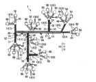
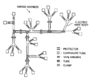
- FIG. 1 is a diagram showing one embodiment of a wiring harness of the present invention and schematic configuration the wiring harness manufactured with a wiring harness manufacturing system.
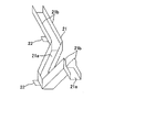
- FIG. 2A is a perspective view of a protector arranged in a trunk portion of the wiring harness in FIG. 1.
- FIG. 2B is a perspective view seeing the protector shown in FIG. 1 from another angle.
- FIG. 3A is a perspective view of a extruder used for forming the protector in FIG. 2.
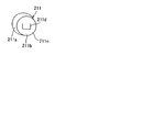
- FIG. 3B is an enlarged perspective view of variable die portion of the extruder in FIG. 2A.
- FIG. 3C is a perspective view of the variable die.
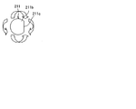
- FIG. 3D is a side perspective view of the variable die.
- FIG. 3E is a diagram illustrating action of a head of the variable die.
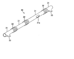
- FIG. 4A is a perspective view of a stretched state of a corrugate tube arranged in a branch portion of the wiring harness in FIG. 1.
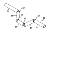
- FIG. 4B is a perspective view of a bending state of the corrugate tube in FIG. 4A.
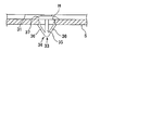
- FIG. 4C is a side view of an attaching clip arranged in a tubular portion of the corrugate tube in FIG. 4A.
- FIG. 5A is a perspective view of a extruder used for forming the corrugate tube in FIGS. 4A to 4C.
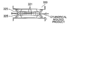
- FIG. 5B is a top view of a forming portion of the extruder in FIG. 5A.
- FIG. 5C is a front view illustrating a shape of a mold block arranged in the forming portion.
- FIG. 5D is a perspective view of the mold block.
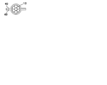
- FIG. 6A is a perspective view of a pair of sheets arranged in a terminal portion of the wiring harness in FIG. 1.
- FIG. 6B is a cross-sectional view of the pair of sheets in a width direction.
- FIG. 6C is a diagram illustrating a method attaching the pair of sheets to the terminal portion.
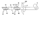
- FIG. 6D is a diagram illustrating a method manufacturing the pair of sheets.
- FIG. 7 is a diagram showing schematic configuration of wiring harness manufacturing system of the present invention.
- FIG. 8 is a diagram showing configuration of a conventional wiring harness.
- FIG. 9 is a diagram illustrating procedure of member used for assembling the conventional wiring harness.
- FIGS. 1 to 6 one embodiment of a wiring harness (A) and a wiring harness manufacturing system (B) in the present invention will be explained with reference to FIGS. 1 to 6.
- the wiring harness which is arranged in a vehicle as an assembly object will be explained.
- the wiring harness is electrically connected between a plurality of electric components mounted on the vehicle, or between the electric component and a battery.
- the wiring harness transmits a desired electric power or signal to the electric components.
- the wiring harness of the present invention may be assembled in a moving object such as airplane or ship, and in device which is fixed and installed in place.
- the wiring harness 1 has an electric wire body 10, a protector 20 as a trunk portion exterior member, a corrugate tube 30 as a branch portion exterior member, a pair of sheets 40 as a terminal portion exterior member, and a connector 50.
- the electric wire body 10 is constructed by bundling a plurality of covered electric wires.
- the covered electric wire has a conductive core wire, and an insulating covered portion.
- the core wire is made of copper, and formed by twisting a plurality of element wires.
- the core wire may consist of one element wire.
- the covered portion is made of insulating synthetic resin, and covers the core wire.
- the electric wire body 10 is divided into a trunk portion 11, a branch portion 12 and a terminal portion 13, and hierarchically-structured.
- the trunk portion 11 is a portion assembled in the vehicle with a state held in a predefined three-dimensional shape based on a shape of an arrangement portion of the vehicle.
- the trunk portion 11 is located at a center of the electric wire body 10, that is, a trunk.
- a plurality of branch portions 12 and a plurality of terminal portion 13 described in below are branched from the trunk portion 11 and provided.
- the trunk portion 11 is one portion which is positioned at a center of the electric wire body 19 and does not include a branch.
- structure of the trunk portion 11 is limited thereto.
- the trunk portion 11 may be branched. If there is a portion assembled in the vehicle with the state held in a predefined three-dimensional shape, structure of the trunk portion 11 is optional unless it is inconsistent with the object of the present invention.
- structure of the trunk portion 11 is suitably defined depending on configuration of the vehicle in which the wiring harness 1 is arranged.
- the branch portion 12 is a portion assembled in a moving object such as a vehicle with a state being able to bend in the electric wire body 10.
- the branch portion 12 is branched from the trunk portion 11 or another branch portion 12, and provided. So, the branch portion 12 is directly or indirectly connected to the trunk portion 11.
- a plurality of the branch portions 12(1) to 12(7) is provided.
- the branch portions 12(1) and 12(7) are arranged in one end of the trunk portion 11, respectively, and divided into two parts.
- the branch portion 12(2) is branched in a halfway position, more specifically a position except the terminal on the side of one end of the trunk portion 11, and arranged.
- the branch portion 12(3) is branched in a halfway position of the branch portion 12(2) on the tip side, and arranged.
- the branch portions 12(4) and 12(5) are arranged in the other end of the trunk portion 11, and divided into two parts.
- the branch portion 12(6) is arranged in a halfway position of the other end of the trunk portion 11, and branched.
- Structure of the branch portions 12 is not limited thereto.
- the structure of the branch portions 12 is optional unless it is inconsistent with the object of the present invention, if there is a portion which is directly or indirectly connected to the trunk portion 11 and is assembled in the moving object with a state being able to bend.
- the structure of the branch portions 12 is defined depending on configuration of a vehicle in which the wiring harness 1 is arranged.
- a terminal portion 13 is connected to the trunk portion 11 or the branch portion 12, and not branched.
- the terminal portion 13 is located at a terminal of the electric wire body 10.
- One end of the terminal portion 13 is connected to the trunk portion 11 or the branch portion 12.
- the other end of the terminal portion 13 is connected to a connector 50.
- the connector 50 is fitted to another connector which is arranged in electric component of the vehicle, and electrically connects the wiring harness 1, namely, electric wire body 10, with the electric component.
- a plurality of the terminal portions 13(1) to 13(9) is provided.
- the one reference numeral is assigned with each branch point which is branched from the trunk portion 11 or the branch portion 12. More specifically, the reference numeral 13 is assigned with two or three terminal portions 13.
- the terminal portions 13(1) to 13(7) are respectively divided into two or three parts, and connected to each tip of the branch portions 12(1) to 12(7).
- the terminal portion 13(8) is divided into three parts at a halfway position of the trunk portion 11 near the center of the trunk portion 11, and arranged.
- the terminal portion 13(9) is arranged in a halfway position near base terminal of the branch portion 12(2), and divided into two parts.
- Structure of the terminal portions 13 described above is not limited thereto.
- the structure of the terminal portions 13 is optional unless it is inconsistent with the object of the present invention, if there is a portion which is connected to the trunk portion 11 or the branch portion 12 without branch, and arranged in the terminal of the electric wire body 10. Practically, the structure of the terminal portions 13 is defined depending on configuration of a vehicle in which the wiring harness 1 is arranged.
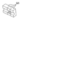
- a protector 20 is arranged in the trunk portion 11 of the electric wire body 10 described above, and made of hard synthetic resin. As shown in FIGS. 2A and 2B, the protector 20 has a shape holding portion 21, and a protector clamp 22 as a trunk portion fixing apparatus.
- the shape holding portion 21 has a belt-shaped bottom wall 21a, and a pair of side walls 21b extending from the opposing edges of the bottom wall 21a in a width direction.
- the shape holding portion 21 is formed into U-shape. Several parts of the shape holding portion 21 in the longitudinal direction are bent in a predefined direction, and the shape holding portion 21 is formed according to the three-dimensional shape.
- a leading slit 21c is arranged in the side wall 21b.
- the leading slit 21c is formed by cutting the side wall 21b in a rectangular shape corresponding to the branch portion 12 and the terminal portion 13 branched from the halfway position of the trunk portion 11.
- the branch portion 12 and the terminal portion 13 divided from the halfway position of the trunk portion 11 are led from the leading slit 21c.
- the shape holding portion 21 is formed depending on the shape of the trunk portion 11 received in the shape holding portion 21. More specifically, each point of the shape holding portion 21 is chanced based on the shape of the trunk portion 11. For example, in the shape holding portion 21, one part of the side wall 21b is deleted, and the height of the other part of the side wall 21b is changed. Furthermore, the shape holding portion 21 receives the trunk portion 11 inside thereof. As a result, the shape holding portion 21 protects the trunk portion 11 from a shock, and maintains the trunk portion 11 with the three-dimensional shape. According to the embodiment of the present invention, since the trunk portion 11 is formed in one without a branch, the shape holding portion 21 is formed in a gutter-shape. However, it is not limited thereto. For example, when the trunk portion 11 is branched, the shape holding portion 21 is formed in accordance with the shape of the trunk portion 11.
- the protector clamp 22 projects from the bottom wall 21a of the shape holding portion 21 and the pair of the side walls 21b, and is integrally formed.
- the protector clamp 22 is formed in a rectangular plate shape, and is a single body.
- a fixing device such as a screw or rivet is inserted into a through hole (not shown) of the protector clamp 22, and the fixing device is attached to a body of a vehicle.
- the protector clamp 22, more specifically, the shape holding portion 21 and the trunk portion 11 received in the shape holding portion 21 are fixed in the body of the vehicle.
- the shape of the protector clamp 22 is not limited thereto.
- the shape thereof may be formed in the same shape as an attaching clip of a corrugate tube 30 described later.
- the shape of the protector clamp 22 is optional unless it is inconsistent with the object of the present invention. More specifically, in the protector 20 corresponding to the exterior member of the trunk portion, the protector clamp 22 corresponding to the fixing apparatus of the trunk portion and fixing the shape holding portion 21 and the vehicle corresponding to an assembly object is integrally formed with the shape holding portion 21.
- the protector 20 is limited to such configuration.
- the protector 20 may be formed in a square-tube or cylinder shape instead of the gutter-shape. If the shape holding portion 21 which receives the trunk portion 11 depending on the three-dimensional shape and is formed in a gutter or cylinder shape is provided, structure of the protector 20 is optional unless it is inconsistent with the object of the present invention.
- Such protector 20 is formed by using synthetic resin which is able to maintain a desired shape, for example, by using acrylonitrile-butadiene-styrene resin (ABS resin) with extrusion-molding.
- ABS resin acrylonitrile-butadiene-styrene resin
- FIGS. 3A to 3E one example of an extruder used for forming the protector 20 is shown.
- a protector extruder 200 shown in FIG. 3A has a resin extrusion portion 210, a robot arm 220, and a control section not shown.
- the extrusion portion 210 melts and mixes thermoplastic resin material of pellet geometry, and then extrudes the resin material from a variable die 211.
- the robot arm 220 deforms molded material before hardening extruded from the variable die 211.
- variable die 211 is located at the tip of an extrusion cylinder arranged in the protector extruder 200.
- the variable die 211 has a pedestal 211a formed in a circular truncated cone shape, a head 211b rotatably arranged at the pedestal 211a in any direction, and a motor (not shown) rotating the head 211b in a desired direction and changing the shape of a slit 211b arranged in the head 211b.
- the heard 211b includes a flat surface 211c which is formed in a spherical shape.
- the flat surface 211c is formed by cutting a part of the head 211b.
- the slit 211d is located in the center of the flat surface 211c, formed in U-shaped, and pass through the head 211b.
- Opposed portions of the slit 211d, namely, portions corresponding to the pair of the side walls 21b include variable height. More specifically, the variable height is planer view length from a portion (namely, a portion corresponding to the bottom wall 21a) connecting the opposed portions. Thereby, the shape of the slit 211d can be changed, and the height of the side wall 21b can be changed.
- the slit 211d is communicated with the extrusion cylinder. Molten resin material is extruded from the extrusion cylinder through the slit 211d into the exterior. At this time, the head 211b is rotated in a predetermined direction by the motor, and the slit 211d is changed into a predetermined shape.
- the control section of the protector extruder 200 is constructed with a computer, and controls the extrusion portion 210 and the robot arm 220 based on defined control program.
- a predetermined amount of resin is extruded, and the direction of the variable die 211 and the shape of the slit 211d are changed.
- the robot arm 220 the molded material is supported to a predefined height, and bent to a predefined angle. As a result, the extruded molded material before hardening is formed in the three-dimensional shape. Thereafter, the predefined shape is maintained by the robot arm 220 until the molded material is hardened.
- the control section forms the leading slit 21c by cutting a part of the side wall 21b into a rectangular or circular shape with the robot arm 220.
- the branch portion 12 and the terminal portion 13 are led from the leading slit 21c.
- the control section cuts the bottom wall 21a and the side wall 21b into U-shape by the robot arm 220, and forms a rectangular single body by the robot arm 220.
- the single body is bent outside, and a through hole is formed in the center of the single body. Therefore, the protector clam 22 is integrally formed with the shape holding portion 21.
- a member may be separately formed in the same manner as the attaching clip 33 of the corrugate tube 30 described below instead of the single body.
- the member is attached to the shape holding portion 21 with glue and the like.
- the member may be used as the protector clamp 22.In such way, the protector 20 is completed.
- a plurality of various types of protectors 20 including different types of three-dimensional shape can be easily formed by changing the control program of the control section and action of the robot arm 220.
- the corrugate tube 30 made of synthetic resin is arranged in any of the branch portions 12, more specifically, in the branch portions 12(1) to 12(3), and 12(6). As shown in FIG. 4A to 4C, the corrugate tube 30 has a tubular portion 31, a joint portion 32, and the attaching clip 33 as the branch portion fixing apparatus.
- the tubular portion 31 is formed in cylindrical shape so as to receive the branch portion.
- a leading hole 31a is arranged in a part of the tubular portion 31 .
- the other branch portion 12 which is branched from the halfway position of the branch portion 12 and the terminal portion 13 are led from the leading hole 31a.
- the tubular portion 31a is formed in a straight pipe shape, but it is not limited thereto.
- the tubular portion 31 may be bent.
- the joint portion 32 is formed in bellows shape along in an axis direction. More specifically, a concavo portion and a convex portion is arranged in a peripheral wall of the joint portion 32, and alternately located along the axis direction. Thus, the joint portion 32 can be bent.
- the joint portion 32 is integrally arranged with the tubular portion 31 between two tubular portions 31. So, the joint portion 32 is connected to the tubular portions 31 so that the tubular portion 31 is able to bend. Also, the joint portion 32, just like the tubular portion 31, may have the leading hole in which the other branch portion 12 divided from the halfway position of the branch portion 12 or the terminal portion 13 are led.
- the attaching clip 33 has integrally a locking portion 34 vertically arranged from an outer periphery surface of the tubular portion 31, and a support piece 37.
- the locking portion 34 is integrally formed with the outer periphery surface of the tubular portion 31. Furthermore, the locking portion 34 has integrally a columnar standing piece 35 vertically arranged from the outer periphery surface of the tubular portion 31, and a pair of locking pieces 36. One end of the locking piece 36 continues to a tip portion away from the tubular portion 31 in the standing piece 35. The locking pieces 36 extend from one end of the locking piece 36 to the other end thereof so that the locking piece 36 gradually approaches to the tubular portion 31. Furthermore, the locking pieces 36 are arranged away from each other so that the distance between the locking pieces 36 are gradually increased from the one end toward the other end. The locking pieces 36 are able to elastically be deformed in a direction approaching each other.
- the support piece 37 is formed in an annular shape. The inner edge portion of the support piece 37 continues to a base terminal portion near the tubular portion 31 of the standing piece 35. The support piece 37 extends from the standing piece 35 outward of the standing piece 35.
- the locking pieces 36 are elastically deformed once in a direction in which the other end portions approach each other. Thereafter, when the other end portion of the locking piece 36 is entered into the locking hole H, the locking pieces 36 is displaced in a direction in which the other end portions are away from each other by elastic restoring force, and the locking portion 34 is locked in the locking hole H. Therefore, the tubular portion 31 and the branch portion 12 received in the tubular portion 31 are fixed to the vehicle body S.
- the attaching clip 33 (branch portion fixing apparatus) which fixes the tubular portion 31 and the vehicle (assembly object) is arranged in the corrugate tube 30 (branch portion exterior member), and integrally formed with the tubular portion 31.
- Structure of the attaching clip 33 is one example, for example, the attaching clip 33 may be formed in the same shape as the above protector clamp 22. Unless contrary to the object of the present invention, the structure of the attaching clip 33 is optional.
- the corrugate tube 30 may not include the attaching clip 33.
- the corrugate tube 30, for example, is made of synthetic resin such as ABS resin or polycarbonate, and is formed by extrusion-molding.
- FIGS. 5A to 5D one example of the extruder used for molding the corrugate tube 30 is shown.
- a corrugate tube extruder 300 shown in FIG. 5A has a extrusion section 310, a molding section 320, a cooling section 330, a cutting section 340, and a control section not shown.
- the extrusion section 310 melts and mixes thermoplastic resin material of pellet geometry, and then extrudes the resin material from a die in which an annular slit is arranged.
- the cooling section 330 has cooling water in a tank, and cools molded material deformed by the molding section 320 with cooling water.
- the cutting section 340 has a pair of cutting blades located opposed to each other in up and down directions, and cuts the cylindrical molded material cooled with the cooling section 330 a desired length by the pair of the cutting blades.
- the extrusion section 310, the molding section 320, the cooling section 330, and the cutting section 340 is linearly arranged.
- the molding section 320 has a pair of endless belts 321 and a plurality of mold blocks 325.
- the endless belts 321 are arranged opposed to each other and parallel to each other.
- the mold blocks 325 are arranged on the outer periphery surface of the endless belt 321 in parallel in a circumferential direction of the endless belt 321, and formed in a rectangular solid shape.
- each opposed surface of the mold block 325 is closely overlapped.
- a groove formed in a desired shape is arranged in the opposed surface of the mold block 325, the opposed being a surface facing the front in FIG. 5C.
- a groove m1 being a semi-circular shape in cross-section is formed in the opposed surface of the mold block 325(1) forming the tubular portion 31 along the width direction (horizontal direction in FIG. 5C).
- a groove m2 and a groove m3 are formed in the mold block 325(2) forming a part in which the attaching clip 33 is arranged in the tubular portion 31.
- the groove m2 is formed in a semi-circular shape in cross-section, and arranged in the opposed surface along the width direction.
- the groove m3 is made to conform to the outer shape of the attaching clip 33. Additionally, a groove m4 is formed in the mold block 325(3) forming the joint portion 32. The groove m4 is formed in a semi-circular shape in cross-section, and arranged in the opposed surface along the width direction. Moreover, the groove m4 includes a projection portion and a dent portion along a circumferential direction. The projection and dent portions are alternately arranged on a periphery surface of the groove m4 in the width direction. In the inside of the dent portion, a vacuum hole not shown is arranged, and connected to a vacuum machine not shown in drawings.
- the projection of the mold block 325(3) forms the dent portion of the joint portion 32 described above, and the dent portion of the mold block 325(3) forms the projection portion of the joint portion described above.
- a blade may arranged inside of the groove which is arranged in the one mold block 325 and formed in a semi-circular shape in cross-section in the width direction so as to cutting out the cylindrical molded material.
- the structure of the mold block 325 is configured according to the shape of the corrugate tube 30 molded as appropriate.
- the cylindrical molded material extruded from the extrusion section 310 before hardening is sandwiched between the mold blocks 325 opposed to each other in the molding section. Thereby, the resin material is formed in the shape of the groove of the mold block 325.
- the control section of the corrugate tube extruder 300 is constructed with a computer, and controls the extrusion section 310, the molding section 320, and the cutting section 340 based on defined control program.
- the extrusion section 310 a predetermined amount of resin is extruded, and a cylindrical molded material is formed.
- the endless belt is rotated at desired speed, and the tubular portion 31, the joint portion 32 and the attaching clip 33 is formed with the extruded cylindrical molded material before hardening. Thereafter, the cylindrical molded material is hardened by passing through the cooling section 330.
- the cutting section 340 the hardened cylindrical molded material is cut with desired length. In this manner, the corrugate tube 30 is manufactured.
- a plurality of various types of the corrugate tube 30 which differs in the number of the length of the tubular portion 31, the position of the joint portion 32, the attaching clip 33 and so on can be easily formed by changing structure of the mold block 325, for example, type or arrangement of the mold block 325.
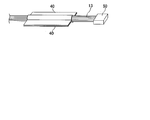
- the terminal portion 13 of the electric wire body 10 includes a pair of sheets 40 made of synthetic resin and having flexibility.
- the pair of the sheets 40 has a sheet main body 41 made of synthetic resin such as polyvinyl chloride (PVC).
- the thickness of the sheet main body 41 is 0.070 mm to 0.250 mm.
- the sheet main body 41 is formed in a thin-film band-like shape.
- the length of the sheet main body 41 is the same length as the terminal portion 13 in which the sheet main body 41 is attached, and the width thereof is formed so that the terminal portion 13 is sandwiched between the sheet main bodies 41.
- One of the pair of the sheets 40 includes an adhesion portion 42 in which adhesive material is applied to both edges of the sheet main body 41 in the width direction. Thereby, the pair of the sheets 40 are pasted on each other with a state sandwiching the terminal portion 13 between the sheets 40, and covers the terminal portion 13.
- the pair of the sheets 40 is manufactured by a sheet cutting machine 400 including a pair of blades C and an adhesion forming section N.
- the blades C are arranged opposed to each other in a vertical direction.
- the adhesion forming section N is arranged close to the blades C. More specifically, sheet base material K having the desired thickness and width and wound with roll shape is cut by the pair of the blades C with the length depending on the terminal portion 13 being an installation object. As a result, the sheet main body 41 is formed. If necessary, in the adhesion forming section N, adhesive material is applied to the both edges of the sheet main body 41 in the width direction, and the adhesion portion 42 is formed. Then, the pair of the sheets 40 is manufactured.
- the sheet 40 includes the sheet main body 41 made of PVC, but it is not limited thereto.
- the sheet main body 40 may be made of polypropylene (PP), and may be formed with a lamination sheet in which an elastic layer made of expanded polypropylene is laminated on an epidermal layer.
- the structure of the sheet 40 is optional unless contrary to the object of the present invention.
- one sheet may be wound on the terminal portion.
- the above electric wire body 10, the protector 20, the corrugate tube 30 and the pair of the sheets 40 are manufactured by each independent process in advance, respectively.
- the trunk portion 11 of the electric wire body 10 is received in the shape holding portion 21 of the protector 20, and the branch portion 12 and the terminal portion 13 are led from the both ends of the shape holding portion 21 and the leading slit 21c. As a result, the trunk portion 11 is maintained with a desired three-dimensional shape. Furthermore, since the protector 20 holds the wiring harness 1 to the desired three-dimensional shape, and is also assembly jig of the wiring harness 1, later assembly becomes easy.
- branch portions 12(1)-12(3), 12(6) of the electric wire body 10 are inserted into the corrugate tube 30 formed according to the shape of the branch portions.
- the other branch portion 12 which arranged in the tip of the branch portion and the halfway position and the terminal portion 13 are led from the tip of the corrugate tube 30 and the leading hole 31a.
- the terminal portions 13(1)-13(9) of the electric wire body 10 are sandwiched with the pair of the sheets 40 formed according to the length of the terminal portions, and the sheets 40 are applied so that the sheets 40 adhere each other. In this manner, the wiring harness 1 is completed.
- the electric wire body 10 of the wiring harness 1 has the one trunk portion 11, the plurality of the branch portions 12, and the plurality of the terminal portions 13.
- the trunk portion 11 is hierarchically-divided, and assembled on the vehicle with a state maintained in the desired three-dimensional shape.
- the branch portions 12 are directly or indirectly connected to the trunk portion 11, and assembled on the vehicle with a flexible state.
- the terminal portions 13 are connected to the trunk portion 11 or the branch portion 12, and are not branched.
- the trunk portion 11 has the protector 20 including the shape holding portion 21 formed in a gutter shape along the three-dimensional shape, and receiving the trunk portion 11 in the shape holding portion 21.
- the corrugate tube 30 is arranged in some or all of the branch portions 12, and has the tubular portion 31 receiving the branch portions 12 and the joint portion 32 flexibly connected to the tubular portion 31. Furthermore, the pair of the sheets 40 sandwiching the terminal portion 13 between them are arranged in the terminal portions 13. That is, the electric wire body 10 is divided into hierarchical three parts, more specifically, mainly on the trunk portion 11, the branch portion 12 and the terminal portion 13. In the three types portions, the protector 20, the corrugate tube 30 and the pair of the sheets 40 as the exterior member corresponding to them are provided respectively.
- the protector 20 has the protector clamp 22 which fixes the shape holding portion 21 and the vehicle body of the vehicle, and is integrally formed with the shape holding portion 21. Therefore, the number of parts can be reduced. In addition, assembling man-hour of the wiring harness 1 can be further reduced, and the wiring harness 1 can be more easily assembled.
- the corrugate tube 30 has the attaching clip 33 which fixes the tubular portion 31 and the vehicle body of the vehicle, and is integrally formed with the tubular portion 31. Therefore, the number of parts can be reduced. In addition, assembling man-hour of the wiring harness 1 can be further reduced, and the wiring harness 1 can be more easily assembled.
- the corrugate tube 30 is arranged in several branch portions 12 of the branch portions 12, however, it is limited thereto.
- the corrugate tube 30 may be arranged in all of the branch portions 12.
- the pair of the sheets 40 are arranged in all of the terminal portions 13 in the embodiment, but it is limited thereto.
- the sheets 40 may be arranged in several terminal portions 13 of the plurality of the terminal portions 13.
- a wiring harness manufacturing system 500 has a main belt conveyor 510, an electric wire body manufacturing portion 511, a protector attaching portion 512, a corrugate tube attaching portion 513, a sheet attaching portion 514, a first sub-belt conveyor 520, a second sub-belt conveyor 530, a third sub-belt conveyor 540, the protector extruder 200 as a first extruder, the corrugate tube extruder 300 as a second extruder, the sheet cutting machine 400, and a control unit not shown.
- the wiring harness manufacturing system 500 is placed in one factory.
- the wiring harness manufacturing system 500 may be located between two rooms of the one factory. That is, each section may be located close to each other in one factory so that manufacturing stream is not separated.
- the main belt conveyor 510 is an apparatus transmitting a working pallet performing an assembly work of the wiring harness 1 along an assembly work process.
- the electric wire body manufacturing portion 511 is provided in end of upper process of the main belt conveyor 510.
- the protector attaching portion 512, the corrugate tube 513, and the sheet attaching portion 514 are provided toward bottom process.
- the protector attaching portion 512 is a working space for attaching the protector 20 to the trunk portion 11 of the electric wire body 10.
- the corrugate tube 513 is a working space for attaching the corrugate tube 30 to the branch portions 12 of the electric wire body 10.
- the sheet attaching portion is a working space for attaching the pair of the sheets 40 to the terminal portions 13 of the electric wire body 10.
- the electric wire body manufacturing portion 511 has a working robot manufacturing the electric wire body 10 from a plurality of covered electric wires.
- the protector attaching portion 512 has a working robot attaching the protector 20 to the trunk portion 11.
- the corrugate tube attaching portion 51 has a working robot attaching the corrugate tube 30 to each branch portion 12.
- the sheet attaching portion 514 has a working robot attaching the pair of the sheets 40 to each terminal portion 13. Instead of the working robots, workers for performing the attachment of each exterior member may be arranged.
- the protector attaching portion 512 corresponds to first subassembly portion in claims
- the corrugate tube attaching portion 513 corresponds to second subassembly portion in claims
- the sheet attaching portion 514 corresponds to third subassembly portion in claims. Furthermore, assembly in claims is constructed with the protector attaching portion 512, the corrugate tube 513 and the sheet attaching portion 514.
- the main belt conveyor 510 conveys the working pallet from the electric wire manufacturing portion 511 toward the bottom process.
- the protector attaching portion 512, the corrugate tube attaching portion 513 and the sheet attaching portion 514 arrive at the working pallet such as a working table, the main belt conveyor 510 let the working pallet stay until the attaching work is finished in each attaching portion. That is, the action of the main belt conveyor 510 is stopped temporarily (halt of transportation).
- the first sub-belt conveyor 520 corresponds to first transportation mechanism in claims, and is arranged between the protector extruder 200 and the protector attaching portion 512. Furthermore, the first sub-belt conveyor 520 conveys the protector 20 manufactured by extrusion-molded with the protector extruder 200 to the protector attaching portion 512.
- the second sub-belt conveyor 530 corresponds to second transportation mechanism in claims, and is arranged between the corrugate tube extruder 300 and the corrugate tube attaching portion 513. Furthermore, the second sub-belt conveyor 530 conveys the corrugate tube 30 manufactured by the corrugate tube extruder 300 to the corrugate tube attaching portion 513.
- the third sub-belt conveyor 540 corresponds to third transportation mechanism in claims, and is arranged between the sheet cutting machine 400 and the sheet attaching portion 514. Furthermore, the third sub-belt conveyor 540 conveys the sheet 40 manufactured by the sheet cutting machine 400 to the sheet attaching portion 514.
- the control unit for example, is constructed with a computer, and is connected to the main belt conveyor 510, the protector attaching portion 512, the corrugate tube attaching portion 513, the sheet attaching portion 514, the first sub-belt conveyor 520, the second sub-belt conveyor 530, the third sub-belt conveyor 540, the protector extruder 200 as the first extruder, the corrugate tube extruder 300 as the second extruder, the sheet cutting machine 400.
- the control unit controls each portion connected thereto by transmitting and receiving control signal between each portion and the control unit. More specifically, the control unit monitors work state of the electric wire body manufacturing portion 511, the protector attaching portion 512, the corrugate tube 513 and the sheet attaching portion 514.
- control unit adjusts speed for moving the working pallet in the main belt conveyor 510 in response to the work state, for supplying each exterior member to each attaching portion 512, 513, 514, and for manufacturing of each exterior member in the protector extruder 200, the corrugate tube extruder 300, and the sheet cutting machine 400.
- the electric wire body manufacturing portion 511 a plurality of covered electric wires is bundled, and those ends are attached to the connector 50.
- the electric wire body 10 is manufactured.
- the protector 20 corresponding to the trunk portion 11 of the electric wire body 10 is manufactured from a predefined resin material by the protector extruder 200.
- the corrugate tubes 30 corresponding to the branch portions 12 of the electric wire body 10 are manufactured from a predefined resin material by the corrugate tube extruder 300.
- a plurality of the pair of sheets 40 corresponding to the terminal portions 13 of the electric wire body 10 are manufactured from sheet base material by the sheet cutting machine 400.
- the electric wire body 10 is temporarily fixed on the working pallet with an assembly jig, and the working pallet is conveyed to the protector attaching portion 512 by the main belt conveyor 510.
- the protector 20 manufactured by the protector extruder 200 is conveyed to the protector attaching portion 512 by the first sub-belt conveyor 520.
- the protector 20 is attached to the trunk portion 11 of the electric wire body 10. After the attachment is finished, the working pallet is conveyed to the corrugate tube attaching portion 513 by the main belt conveyor 510. At the same time, the plurality of the corrugate tubes 30 are conveyed to the corrugate tube attaching portion 513 by the second sub-belt conveyor 530.
- the corrugate tubes 30 are attached to the branch portions 12 of the electric wire body 10, respectively.
- the working pallet is conveyed to the sheet attaching portion 514 by the main belt conveyor 510.
- a plurality of the pair of sheets 40 manufactured with the sheet cutting machine 400 are conveyed to the sheet attaching portion 514 by the third sub-belt conveyor 540.
- the pair of sheets 40 are attached to the terminal portions 13 of the electric wire body 10, respectively.
- the working pallet is conveyed to bottom step by the main belt conveyor 510, and the electric wire body 10 to which various types of exterior members are attached is removed from the working pallet. As a result, the wiring harness 1 is completed.
- the electric wire body 10 arranged in the wiring harness 1 being a manufacturing object has the one trunk portion 11, the plurality of the branch portions 12, and the plurality of the unbranched terminal portions 13.
- the trunk portion 11 is hierarchically-divided, and assembled on the vehicle with a state maintained in a desired three-dimensional shape.
- the branch portions 12 are directly or indirectly connected to the trunk portion 11, and assembled on the vehicle with a flexible state.
- the terminal portions 13 are connected to the trunk portion 11 or the branch portion 12, and are not branched.
- the trunk portion 11 has the protector 20 including the shape holding portion 21 formed in a gutter shape along the three-dimensional shape, and receiving and maintaining the trunk portion 11 in the shape holding portion 21.
- the corrugate tube 30 is arranged in some or all of the branch portions 12, and has the tubular portion 31 receiving the branch portions 12 and the joint portion 32 flexibly connected to the tubular portion 31. Furthermore, the pair of the sheets 40 covering the terminal portion 13 are arranged in all the terminal portions 13.
- the electric wire body 10 arranged in the wiring harness 1 being the manufacturing object is divided into hierarchical three parts, more specifically, mainly on the trunk portion 11, the branch portion 12 and the terminal portion.
- the protector 20, the corrugate tube 30 and the pair of the sheets 40 as the exterior member corresponding to them are provided respectively.
- devices for manufacturing the protector 1, the corrugate tube 30, and the pair of the sheets 40, respectively, the protector attaching portion 512, the corrugate tube attaching portion 513, and the sheet attaching portion 514 are located in one factory.
- the protector 1, the corrugate tube 30 and the sheets 40 are the exterior member required to assembly the wiring harness 1, and the protector attaching portion 512, the corrugate tube attaching portion 513, and the sheet attaching portion 514 attach each exterior member manufactured by each device to the electric wire body 10.
- the wiring harness 1 being the manufacturing object has a low number of the exterior members required for assembly. Therefore, the protector extruder 200 manufacturing the exterior member required for assembly of the wiring harness 1, the corrugate tube extruder 300 manufacturing the exterior member required for assembly of the wiring harness 1 and the sheet cutting machine 400 manufacturing the exterior member required for assembly of the wiring harness 1 can be located in one factory. Furthermore, since the protector extruder 200, the corrugate tube extruder 300, the sheet cutting machine 400, the protector attaching portion 512, the corrugate tube attaching portion 513, and the sheet attaching portion 514 are arranged in one factory, transportation from another factory is not required. As a result, distribution cost can be reduced, and the wiring harness 1 can be cheaply manufactured.
- the protector 20 extrusion-molded, namely manufactured by the first sub-belt conveyor 520 is conveyed to the protector attaching portion 512, it is unnecessary to manage part number of the protector 20. So, management cost when conveying the protector 20 can be reduced, and the wiring harness 1 can be more cheaply manufactured.
- the corrugate tube 30 extrusion-molded, namely, manufactured by the second sub-belt conveyor 530 is conveyed to the corrugate tube attaching portion 513, it is unnecessary to manage part number of the corrugate tube 30. As a result, management cost when conveying the corrugate tube 30 can be reduced, and the wiring harness 1 can be more cheaply manufactured.
- the pair of the sheets 40 cut, namely, manufactured by the third sub-belt conveyor 540 are conveyed to the sheet attaching portion 514, it is not required to manage part number of the pair of the sheets 40. Thus, management cost when conveying the pair of the sheets 40 can be reduced, and the wiring harness 1 can be more cheaply manufactured.
- the first sub-belt conveyor 520, the second sub-belt conveyor 530, and the third sub-belt conveyor 540 are provided, but it is not limited.
- a carriage may be provided. when the carriage is used, the protector 20, the corrugate tube 30, and the pair of the sheets 40 may be automatically conveyed or conveyed by hand.
- the main belt conveyor 510 is provided, and the electric wire body manufacturing portion 511, the protector attaching portion 512, the corrugate tube attaching portion 513, and the sheet attaching portion 514 are provided along the main belt conveyor 510, however it is not limited.
- the main belt conveyor 510 may be not provided, and the electric wire body manufacturing portion 511, the protector attaching portion 512, the corrugate tube attaching portion 513, and the sheet attaching portion 514 may be positioned at a distance approaching each other.
- one assembly portion combining the protector attaching portion 512 (namely, the first subassembly portion), the corrugate tube attaching portion 513 (namely, the second subassembly portion), and the sheet attaching portion 514 (namely, the third subassembly portion) may be arranged.
Landscapes
- Engineering & Computer Science (AREA)
- Mechanical Engineering (AREA)
- Details Of Indoor Wiring (AREA)
Abstract
L'invention porte sur un faisceau de câblage (1), lequel faisceau comprend un corps de fils électriques (10) divisé en une partie tronc (11), une pluralité de parties ramifiées (12) connectées à la partie tronc, et une pluralité de parties terminales non ramifiées (13) connectées à la partie tronc ou à la partie ramifiée, et sur un système de fabrication de faisceau de câblage (500), lequel système fournit une extrudeuse de dispositif de protection (200), une extrudeuse de tube ondulé (300), une machine de coupe de feuille (400) et des parties d'attachement du dispositif de protection, du tube ondulé et de la feuille dans une usine. La partie tronc comporte un dispositif de protection (20) comprenant une partie de maintien de forme (21) formée sous une forme de gouttière le long d'une forme en trois dimensions prédéfinie et recevant la partie tronc (11) dans la partie de maintien de forme. Dans certaines des parties ramifiées, un tube ondulé (30) est disposé, et a une partie tubulaire (31) recevant la partie ramifiée (12) et une partie de raccord (32) reliant de façon souple la partie tubulaire. Dans toutes les parties de terminal, une paire de feuilles (40) prenant en sandwich la partie de terminal (13) entre celles-ci sont disposées.
Priority Applications (2)
| Application Number | Priority Date | Filing Date | Title |
|---|---|---|---|
| CN201280028039.3A CN103596807B (zh) | 2011-06-07 | 2012-05-31 | 线束和线束制造系统 |
| ZA2013/08925A ZA201308925B (en) | 2011-06-07 | 2013-11-27 | Wiring harness and wiring harness manufacturing system |
Applications Claiming Priority (4)
| Application Number | Priority Date | Filing Date | Title |
|---|---|---|---|
| JP2011127031A JP5984341B2 (ja) | 2011-06-07 | 2011-06-07 | ワイヤハーネス |
| JP2011-127031 | 2011-06-07 | ||
| JP2011-127032 | 2011-06-07 | ||
| JP2011127032A JP5731910B2 (ja) | 2011-06-07 | 2011-06-07 | ワイヤハーネス製造システム |
Publications (1)
| Publication Number | Publication Date |
|---|---|
| WO2012169158A1 true WO2012169158A1 (fr) | 2012-12-13 |
Family
ID=46275942
Family Applications (1)
| Application Number | Title | Priority Date | Filing Date |
|---|---|---|---|
| PCT/JP2012/003571 Ceased WO2012169158A1 (fr) | 2011-06-07 | 2012-05-31 | Faisceau de câblage et système de fabrication de faisceau de câblage |
Country Status (3)
| Country | Link |
|---|---|
| CN (1) | CN103596807B (fr) |
| WO (1) | WO2012169158A1 (fr) |
| ZA (1) | ZA201308925B (fr) |
Cited By (5)
| Publication number | Priority date | Publication date | Assignee | Title |
|---|---|---|---|---|
| WO2014188988A1 (fr) * | 2013-05-21 | 2014-11-27 | 矢崎総業株式会社 | Dispositif et procédé de fixation d'élément extérieur |
| FR3010169A1 (fr) * | 2013-09-03 | 2015-03-06 | Peugeot Citroen Automobiles Sa | Gaine deformable a sous-partie(s) rigidifiee(s) et contigue(s) a une sous-partie offrant un jeu |
| CN104904084A (zh) * | 2012-12-25 | 2015-09-09 | 矢崎总业株式会社 | 线束 |
| CN111029994A (zh) * | 2018-10-09 | 2020-04-17 | 住友电装株式会社 | 配线部件 |
| EP3742046A1 (fr) | 2019-05-20 | 2020-11-25 | Gureak Lanean S.A. | Procédé et dispositif pour agencement de câbles dans un phare automobile |
Families Citing this family (5)
| Publication number | Priority date | Publication date | Assignee | Title |
|---|---|---|---|---|
| JP2016192354A (ja) * | 2015-03-31 | 2016-11-10 | 株式会社オートネットワーク技術研究所 | ワイヤーハーネスの製造方法及びコネクタ保持部支持装置 |
| JP6652036B2 (ja) * | 2016-11-07 | 2020-02-19 | 株式会社オートネットワーク技術研究所 | ワイヤーハーネス及びワイヤーハーネスの製造方法 |
| CN107833689A (zh) * | 2017-10-25 | 2018-03-23 | 中国航空无线电电子研究所 | 一体化线缆集束 |
| CN108944734A (zh) * | 2018-07-09 | 2018-12-07 | 利辛县江淮扬天汽车有限公司 | 一种汽车电子控制用线路保护支撑装置 |
| CN110556677B (zh) * | 2019-09-06 | 2024-08-20 | 沈阳兴华航空电器有限责任公司 | 一种防火及抗电磁干扰的线束结构 |
Citations (12)
| Publication number | Priority date | Publication date | Assignee | Title |
|---|---|---|---|---|
| US2991328A (en) * | 1959-04-06 | 1961-07-04 | Chance Vought Corp | Multiconductor cable |
| DE3710642A1 (de) * | 1987-03-31 | 1988-10-20 | Leonische Drahtwerke Ag | Kabelbaum, insbesondere fuer kraftfahrzeuge |
| WO1993018565A1 (fr) * | 1992-03-11 | 1993-09-16 | United Technologies Automotive, Inc. | Conduit pour faisceau de cables |
| EP0562189A1 (fr) * | 1992-03-27 | 1993-09-29 | United Technologies Automotive (Uk) Limited | Fabrication de peignes de câbles |
| EP0566969A2 (fr) * | 1992-04-16 | 1993-10-27 | Leonische Drahtwerke AG | Procédé de la fabrication d'un peigne de câbles |
| EP0709252A1 (fr) * | 1994-10-26 | 1996-05-01 | Leonische Drahtwerke AG | Faisceau de câbles en particulier pour le montage dans une carosserie de voiture |
| US5918365A (en) * | 1995-07-20 | 1999-07-06 | Yazaki Corporation | Wire harness manufacturing method |
| US6120327A (en) * | 1997-07-22 | 2000-09-19 | Lear Automotive Dearborn, Inc. | Foam wire harness with shape memory |
| US6156973A (en) * | 1997-06-30 | 2000-12-05 | Yazaki Corporation | Foam covered tube for wiring harnesses |
| JP2007059298A (ja) * | 2005-08-26 | 2007-03-08 | Yazaki Corp | ワイヤハーネス |
| US20090241331A1 (en) * | 2008-03-25 | 2009-10-01 | Commercial Vehicle Group, Inc. | System and Method of Forming a Protective Covering for a Wire Harness |
| WO2012077831A1 (fr) * | 2010-12-10 | 2012-06-14 | Yazaki Corporation | Dispositif de fabrication de harnais de fils |
Family Cites Families (1)
| Publication number | Priority date | Publication date | Assignee | Title |
|---|---|---|---|---|
| JP4098192B2 (ja) * | 2003-08-25 | 2008-06-11 | 矢崎総業株式会社 | ワイヤーハーネスの止水部形成方法 |
-
2012
- 2012-05-31 WO PCT/JP2012/003571 patent/WO2012169158A1/fr not_active Ceased
- 2012-05-31 CN CN201280028039.3A patent/CN103596807B/zh not_active Expired - Fee Related
-
2013
- 2013-11-27 ZA ZA2013/08925A patent/ZA201308925B/en unknown
Patent Citations (12)
| Publication number | Priority date | Publication date | Assignee | Title |
|---|---|---|---|---|
| US2991328A (en) * | 1959-04-06 | 1961-07-04 | Chance Vought Corp | Multiconductor cable |
| DE3710642A1 (de) * | 1987-03-31 | 1988-10-20 | Leonische Drahtwerke Ag | Kabelbaum, insbesondere fuer kraftfahrzeuge |
| WO1993018565A1 (fr) * | 1992-03-11 | 1993-09-16 | United Technologies Automotive, Inc. | Conduit pour faisceau de cables |
| EP0562189A1 (fr) * | 1992-03-27 | 1993-09-29 | United Technologies Automotive (Uk) Limited | Fabrication de peignes de câbles |
| EP0566969A2 (fr) * | 1992-04-16 | 1993-10-27 | Leonische Drahtwerke AG | Procédé de la fabrication d'un peigne de câbles |
| EP0709252A1 (fr) * | 1994-10-26 | 1996-05-01 | Leonische Drahtwerke AG | Faisceau de câbles en particulier pour le montage dans une carosserie de voiture |
| US5918365A (en) * | 1995-07-20 | 1999-07-06 | Yazaki Corporation | Wire harness manufacturing method |
| US6156973A (en) * | 1997-06-30 | 2000-12-05 | Yazaki Corporation | Foam covered tube for wiring harnesses |
| US6120327A (en) * | 1997-07-22 | 2000-09-19 | Lear Automotive Dearborn, Inc. | Foam wire harness with shape memory |
| JP2007059298A (ja) * | 2005-08-26 | 2007-03-08 | Yazaki Corp | ワイヤハーネス |
| US20090241331A1 (en) * | 2008-03-25 | 2009-10-01 | Commercial Vehicle Group, Inc. | System and Method of Forming a Protective Covering for a Wire Harness |
| WO2012077831A1 (fr) * | 2010-12-10 | 2012-06-14 | Yazaki Corporation | Dispositif de fabrication de harnais de fils |
Cited By (9)
| Publication number | Priority date | Publication date | Assignee | Title |
|---|---|---|---|---|
| CN104904084A (zh) * | 2012-12-25 | 2015-09-09 | 矢崎总业株式会社 | 线束 |
| CN104904084B (zh) * | 2012-12-25 | 2018-01-12 | 矢崎总业株式会社 | 线束 |
| US10286857B2 (en) | 2012-12-25 | 2019-05-14 | Yazaki Corporation | Wire harness |
| WO2014188988A1 (fr) * | 2013-05-21 | 2014-11-27 | 矢崎総業株式会社 | Dispositif et procédé de fixation d'élément extérieur |
| FR3010169A1 (fr) * | 2013-09-03 | 2015-03-06 | Peugeot Citroen Automobiles Sa | Gaine deformable a sous-partie(s) rigidifiee(s) et contigue(s) a une sous-partie offrant un jeu |
| CN111029994A (zh) * | 2018-10-09 | 2020-04-17 | 住友电装株式会社 | 配线部件 |
| CN111029994B (zh) * | 2018-10-09 | 2022-01-14 | 住友电装株式会社 | 配线部件 |
| EP3742046A1 (fr) | 2019-05-20 | 2020-11-25 | Gureak Lanean S.A. | Procédé et dispositif pour agencement de câbles dans un phare automobile |
| WO2020234396A1 (fr) | 2019-05-20 | 2020-11-26 | Gureak Lanean S.A. | Procédé et dispositif d'agencement de câble dans une lampe d'automobile |
Also Published As
| Publication number | Publication date |
|---|---|
| CN103596807B (zh) | 2016-04-27 |
| ZA201308925B (en) | 2015-02-25 |
| CN103596807A (zh) | 2014-02-19 |
Similar Documents
| Publication | Publication Date | Title |
|---|---|---|
| WO2012169158A1 (fr) | Faisceau de câblage et système de fabrication de faisceau de câblage | |
| CN103460536B (zh) | 具有闩锁的保护管及用于该具有闩锁的保护管的制造设备 | |
| US20190287700A1 (en) | Wire harness and manufacturing method of sheet material with wire harness | |
| EP2979931B1 (fr) | Structure de fixation de harnais de câblage | |
| EP0235924B1 (fr) | Faisceau de fils moulé | |
| CN103782460B (zh) | 带有路径维持构件的波纹管以及线束 | |
| US20160013625A1 (en) | Wire harness | |
| CN104009424A (zh) | 线束以及线束的制造方法 | |
| CN109313965B (zh) | 线束 | |
| US20130098660A1 (en) | Electric wire protection structure and method for manufacturing electric wire protection structure | |
| US20120325519A1 (en) | Wire protector | |
| EP3434531B1 (fr) | Procédé pour assembler un faisceau de fils, élément d'élimination d'interférence et structure d'assemblage de faisceau de fils | |
| JP5984341B2 (ja) | ワイヤハーネス | |
| US9520702B2 (en) | Clamp-integrated wiring harness protector for assembling and method for producing the same | |
| JP2012124090A (ja) | ワイヤハーネス製造装置 | |
| JP2013149512A (ja) | ワイヤハーネスの製造方法、ワイヤハーネスの製造装置 | |
| JP5731910B2 (ja) | ワイヤハーネス製造システム | |
| WO2015115164A1 (fr) | Élément extérieur de fil électrique, module de fils électriques et procédé de fabrication d'élément extérieur de fil électrique | |
| JP2015186284A (ja) | 固定具、ワイヤーハーネスユニット、およびワイヤーハーネスユニットの製造方法 | |
| JP6211386B2 (ja) | ハーネス外装保護材の製造方法 | |
| JP2025120590A (ja) | ワイヤハーネス | |
| JP2020053361A (ja) | ワイヤーハーネス | |
| JP2018146787A (ja) | 光ファイバケーブルおよび光ファイバケーブルの製造方法 | |
| JP2013055754A (ja) | コルゲートチューブ、コルゲートチューブの組立方法及びワイヤーハーネス保護構造体 | |
| JP2018098944A (ja) | ワイヤハーネス用ブラケット及びワイヤハーネス用ブラケットの製造方法 |
Legal Events
| Date | Code | Title | Description |
|---|---|---|---|
| WWE | Wipo information: entry into national phase |
Ref document number: 201280028039.3 Country of ref document: CN |
|
| 121 | Ep: the epo has been informed by wipo that ep was designated in this application |
Ref document number: 12727449 Country of ref document: EP Kind code of ref document: A1 |
|
| NENP | Non-entry into the national phase |
Ref country code: DE |
|
| 122 | Ep: pct application non-entry in european phase |
Ref document number: 12727449 Country of ref document: EP Kind code of ref document: A1 |