WO2012169174A1 - 画像処理装置および画像処理方法 - Google Patents
画像処理装置および画像処理方法 Download PDFInfo
- Publication number
- WO2012169174A1 WO2012169174A1 PCT/JP2012/003682 JP2012003682W WO2012169174A1 WO 2012169174 A1 WO2012169174 A1 WO 2012169174A1 JP 2012003682 W JP2012003682 W JP 2012003682W WO 2012169174 A1 WO2012169174 A1 WO 2012169174A1
- Authority
- WO
- WIPO (PCT)
- Prior art keywords
- image
- blank
- input
- value
- parameter
- Prior art date
- Legal status (The legal status is an assumption and is not a legal conclusion. Google has not performed a legal analysis and makes no representation as to the accuracy of the status listed.)
- Ceased
Links
Images








Classifications
-
- G—PHYSICS
- G06—COMPUTING OR CALCULATING; COUNTING
- G06T—IMAGE DATA PROCESSING OR GENERATION, IN GENERAL
- G06T3/00—Geometric image transformations in the plane of the image
-
- G—PHYSICS
- G06—COMPUTING OR CALCULATING; COUNTING
- G06T—IMAGE DATA PROCESSING OR GENERATION, IN GENERAL
- G06T15/00—Three-dimensional [3D] image rendering
- G06T15/10—Geometric effects
- G06T15/20—Perspective computation
- G06T15/205—Image-based rendering
-
- G—PHYSICS
- G06—COMPUTING OR CALCULATING; COUNTING
- G06T—IMAGE DATA PROCESSING OR GENERATION, IN GENERAL
- G06T7/00—Image analysis
- G06T7/50—Depth or shape recovery
-
- H—ELECTRICITY
- H04—ELECTRIC COMMUNICATION TECHNIQUE
- H04N—PICTORIAL COMMUNICATION, e.g. TELEVISION
- H04N13/00—Stereoscopic video systems; Multi-view video systems; Details thereof
- H04N13/10—Processing, recording or transmission of stereoscopic or multi-view image signals
- H04N13/106—Processing image signals
- H04N13/111—Transformation of image signals corresponding to virtual viewpoints, e.g. spatial image interpolation
-
- H—ELECTRICITY
- H04—ELECTRIC COMMUNICATION TECHNIQUE
- H04N—PICTORIAL COMMUNICATION, e.g. TELEVISION
- H04N13/00—Stereoscopic video systems; Multi-view video systems; Details thereof
- H04N13/10—Processing, recording or transmission of stereoscopic or multi-view image signals
- H04N13/106—Processing image signals
- H04N13/128—Adjusting depth or disparity
Definitions
- the present invention relates to an image processing apparatus and an image processing method for generating a converted image by performing projective conversion on a three-dimensional model obtained from an input image.
- GUI Graphic User Interface
- a method of generating a subject image by synthesizing input images obtained by photographing subjects from a plurality of directions to generate a three-dimensional model, and performing projective transformation from an arbitrary viewpoint position in the generated three-dimensional model For example, refer to Patent Document 1).
- a method for example, it is possible to obtain a subject image that is photographed with the camera close to the subject or a subject image that is photographed from a different direction from the actual camera.
- the image quality of the converted image may be greatly deteriorated.
- an object of the present invention has been made in view of the above-described problems, and suppresses deterioration in image quality of a converted image when a converted image is generated by performing projective transformation on a three-dimensional model obtained from an input image. It is to provide an image processing apparatus and an image processing method that can be performed.
- An image processing apparatus relates to a data input unit that receives input of an input image, depth data indicating the depth of the input image, and imaging parameters of the input image, and projective conversion of a three-dimensional model.
- a conversion image is generated by performing projective conversion based on the conversion parameter in a parameter input unit that receives input of a conversion parameter that is a parameter, and a three-dimensional model obtained from the input image, the depth data, and the imaging parameter
- a converted image generation unit a blank region detection unit that detects a blank region that is a set of blank pixels that are pixels in which no corresponding pixel exists in the input image, and a size of the blank region.
- an output unit that outputs the converted image when a blank value to be indicated is equal to or less than a threshold value.
- a recording medium such as a system, a method, an integrated circuit, a computer program, or a computer-readable CD-ROM (Compact Disc Read Only Memory). You may implement
- deterioration of the image quality of the converted image can be suppressed.
- FIG. 1 is a block diagram illustrating a functional configuration of the image processing apparatus according to the first embodiment.
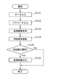
- FIG. 2 is a flowchart showing the processing operation of the image processing apparatus according to the first embodiment.
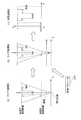
- FIG. 3 is a diagram for explaining an example of a process performed by the converted image generation unit according to the first embodiment.
- FIG. 4 is a diagram for explaining an example of processing by the converted image generation unit according to the first embodiment.
- FIG. 5 is a diagram for explaining an example of processing performed by the converted image generation unit according to the first embodiment.
- FIG. 6 is a block diagram illustrating a functional configuration of the image processing apparatus according to the second embodiment.
- FIG. 7 is a flowchart showing the processing operation of the image processing apparatus according to the second embodiment.
- FIG. 8 is a block diagram illustrating a functional configuration of the image processing apparatus according to the third embodiment.
- FIG. 9 is a flowchart showing the processing operation of the image processing apparatus according to the third embodiment.
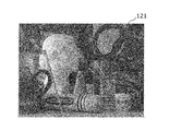
- FIG. 10A is a diagram illustrating an example of an input image.
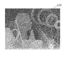
- FIG. 10B is a diagram illustrating an example of depth data.
- FIG. 11 is a diagram illustrating an example of a GUI in an initial state.
- FIG. 12 is a diagram illustrating an example of a GUI that displays a converted image generated based on input conversion parameters.
- FIG. 13 is a diagram illustrating an example of a GUI that displays a converted image (blank value> threshold value) generated based on the interpolation conversion parameter.
- FIG. 10A is a diagram illustrating an example of an input image.
- FIG. 10B is a diagram illustrating an example of depth data.
- FIG. 11 is a diagram illustrating an example of a GUI in an initial state.
- FIG. 12 is a diagram illustrating
- FIG. 15 is a diagram illustrating an example of a converted image obtained by complementing a blank area.
- FIG. 16 is a block diagram showing a functional configuration of a display device according to a modification of the first to third embodiments.
- the image quality of the converted image may be greatly degraded.
- a blank area in which an image corresponding to the input image does not exist may occur in the converted image generated by projective conversion. In such a case, the image quality of the converted image is greatly degraded.
- an image processing apparatus includes a data input unit that receives input of an input image, depth data indicating the depth of the input image, and imaging parameters of the input image, and projection of a three-dimensional model.
- a converted image is obtained by performing projective conversion based on the converted parameter in a parameter input unit that receives input of a conversion parameter that is a parameter related to conversion.
- a converted image generating unit that generates a blank area that is a set of blank pixels that are pixels in which no corresponding pixel exists in the input image, and a size of the blank area.
- an output unit that outputs the converted image when the blank value indicating the value is equal to or less than a threshold value.
- the blank area detecting unit detects a plurality of the blank areas such that a set of adjacent blank pixels becomes one blank area
- the output unit detects each blank value of the plurality of blank areas.
- the converted image may be output when the maximum blank value is less than or equal to the threshold value.
- a converted image can be output when the maximum blank value among the blank values of each of the plurality of blank areas is equal to or less than the threshold value. That is, whether or not to output a converted image can be switched according to a blank area that has a large influence on image quality degradation among a plurality of blank areas, and the output of a converted image with greatly deteriorated image quality is suppressed. be able to.
- the blank value may be a value weighted so that the blank value of the blank area becomes larger as the position of the blank area is closer to the center position of the converted image.
- the blank area present at the center of the image has a greater influence on the image quality degradation than the blank area present at the edge of the image. Therefore, according to the present configuration, whether or not to output the converted image using the blank value weighted so that the blank value of the blank area becomes larger as the position of the blank area is closer to the center position of the converted image. Can be switched. That is, whether or not to output a converted image can be switched according to a blank area that has a large influence on image quality degradation among a plurality of blank areas, and the output of a converted image with greatly deteriorated image quality is suppressed. be able to.
- the blank value may be a value weighted so that the blank value of the blank area increases as the aspect ratio of the blank area decreases.
- a blank area having a smaller aspect ratio that is, having a shorter width and width
- it further includes a complementing unit that complements the pixel value of the pixel in the blank area based on the pixel value of the pixel in the vicinity of the blank area, and the output unit has the blank value equal to or less than the threshold value.
- the converted image in which pixel values of the pixels in the blank area are complemented may be output.
- the pixel value of the pixel in the blank area can be complemented based on the pixel value of the pixel in the vicinity of the blank area. Therefore, it is possible to suppress the deterioration of the image quality due to the blank area.
- the parameter input unit receives an instruction to change the viewpoint position with respect to the input image from the user as an input of the conversion parameter, and the converted image generation unit performs projective conversion based on the viewpoint position specified by the conversion parameter. By performing this, the converted image may be generated.
- the projective transformation can be performed based on the instruction to change the viewpoint position for the input image received from the user.
- the output unit may further output information for requesting input of another conversion parameter when the blank value is larger than the threshold value.
- This configuration makes it possible to request input of other conversion parameters when the image quality of the converted image is greatly deteriorated. As a result, it is possible to generate a converted image based on other conversion parameters, and it is possible to generate a converted image in which deterioration of image quality due to a blank area is suppressed.
- the output unit receives information for highlighting an object for receiving an instruction to initialize the conversion parameter from a user, and inputs the other conversion parameter. It may be output as information for requesting.
- the output unit may further output a previously output converted image when the blank value is larger than the threshold value.
- the image processing apparatus further interpolates between a conversion parameter corresponding to the input image and a conversion parameter received by the parameter input unit when the blank value is larger than the threshold value,
- a parameter calculation unit that calculates an interpolation conversion parameter may be provided, and the conversion image generation unit may generate a new conversion image by performing projective conversion based on the calculated interpolation conversion parameter.
- the interpolation conversion parameter closer to the conversion parameter corresponding to the input image than the received conversion parameter can be automatically calculated. Therefore, it is possible to suppress deterioration of the image quality of the converted image.
- the parameter calculation unit may gradually approach the conversion parameter corresponding to the input image from the conversion parameter received by the parameter input unit until the blank value becomes equal to or less than the threshold value.
- the interpolation conversion parameters may be calculated in order, the conversion image generation unit may generate the conversion images in order based on the interpolation conversion parameters, and the output unit may output the conversion images in order.
- the interpolation conversion parameter can be calculated so that the interpolation conversion parameter gradually approaches the conversion parameter corresponding to the input image. Therefore, it is possible to automatically calculate conversion parameters so that the converted image satisfies a predetermined image quality. That is, it is possible to suppress deterioration of the image quality of the converted image.
- the converted images generated based on the interpolation conversion parameters calculated in this way can be output in order. Therefore, it is possible to present to the user like an animation how the image quality of the converted image is improved.
- the output unit may further output information indicating a relationship between the blank value and the threshold value.
- the degree of image quality deterioration can be presented to the user. Therefore, the user operability can be improved in the user interface for performing image processing.
- FIG. 1 is a block diagram illustrating a functional configuration of the image processing apparatus according to the first embodiment.
- the image processing apparatus 100 includes a data input unit 101, a parameter input unit 102, a converted image generation unit 103, a blank area detection unit 104, and an output unit 105.
- the data input unit 101 receives input of an input image 121, depth data 122, and shooting parameters 123.
- input data a combination of the input image 121, the depth data 122, and the shooting parameter 123 is referred to as input data.
- the data input unit 101 reads input data from a storage device such as an HDD (Hard Disk Drive) or a flash memory.
- a storage device such as an HDD (Hard Disk Drive) or a flash memory.
- the data input unit 101 acquires input data from an external device connected via a network.
- the depth data 122 is data indicating the depth of the input image.
- the depth indicates the distance from the camera to the subject.
- the depth data 122 includes, for example, the depth value of each pixel constituting the input image.
- the shooting parameter 123 is a parameter indicating the shooting condition of the input image.
- the imaging parameters include a field angle, a depth front end distance, and a depth rear end distance. Note that the imaging parameter 123 does not necessarily include the angle of view, the front end distance of the depth, and the rear end distance of the depth. For example, if the depth value included in the depth data 122 is a normalized value, the imaging parameter 123 may not include the depth front end distance and the depth rear end distance.
- the parameter input unit 102 receives an input of a conversion parameter 124 that is a parameter related to projective conversion of the three-dimensional model. For example, the parameter input unit 102 receives an instruction to change the viewpoint position with respect to the input image 121 as an input of conversion parameters from the user.
- the conversion parameter 124 is not necessarily an instruction to change the viewpoint position.
- the conversion parameter may be information indicating the type of projective transformation (for example, perspective projection or orthographic projection).
- the conversion parameter 124 may be information indicating the angle of view.
- the converted image generation unit 103 generates a converted image 131 by performing projective conversion based on the conversion parameter 124 in the three-dimensional model obtained from the input image 121, the depth data 122, and the imaging parameter 123. Details of the converted image generation unit 103 will be described later with reference to other drawings.
- the blank area detection unit 104 detects a blank area that is a set of blank pixels in the converted image 131. In the present embodiment, the blank area detection unit 104 detects a blank area so that a set of blank pixels adjacent to each other becomes one blank area.
- a blank pixel is a pixel in the converted image that does not have a corresponding pixel in the input image. That is, a blank pixel is a pixel at a position corresponding to an image that is not shown in the input image. In other words, a blank pixel is a pixel that does not have a pixel value or a pixel whose pixel value remains the initial value.
- the blank area detection unit 104 does not necessarily need to detect a set of adjacent blank pixels as one blank area.
- the blank area detection unit 104 may detect a set of blank pixels that are discretely present (not adjacent to each other) within a predetermined range as one blank area.
- the output unit 105 outputs the converted image 131 when the blank value indicating the size of the blank area is equal to or smaller than the threshold value. In the present embodiment, the output unit 105 outputs the converted image 131 when the maximum blank value among the blank values of each of the plurality of blank areas is equal to or less than the threshold value.
- the ratio of the number of pixels in the blank area to the number of pixels in the converted image 131 is used as the blank value.
- the blank value is not necessarily such a value.
- the blank value may be the number of pixels or the area of the blank area.
- the blank value may be at least one of the horizontal width and the vertical width of the blank area.
- FIG. 2 is a flowchart showing the processing operation of the image processing apparatus 100 according to the first embodiment.
- FIG. 2 is a flowchart showing the processing operation of the image processing apparatus 100 according to the first embodiment.
- an instruction to change the viewpoint position is input from the user will be described.
- the data input unit 101 accepts input of input data (S101).
- the parameter input unit 102 receives an input of a viewpoint position change instruction (conversion parameter) from the user (S102).
- the parameter input unit 102 acquires, for example, an instruction to change the viewpoint position input to the input image displayed on the screen.
- the user inputs a viewpoint position change instruction by instructing a position on the screen via an input unit such as a mouse.
- the converted image generation unit 103 generates a converted image by performing projective conversion by changing the viewpoint position in accordance with the change instruction in the three-dimensional model obtained from the input image, the depth data, and the imaging parameters (S103). The process for generating the converted image will be described later.
- the blank area detection unit 104 detects a blank area in the converted image (S104).
- the blank area detection unit 104 detects a set of blank pixels adjacent to each other as one blank area.
- the blank area detection unit 104 determines whether or not the blank value is equal to or less than a threshold value (S105). Specifically, when a plurality of blank areas are detected, the blank area detection unit 104 determines whether the maximum blank value is equal to or less than a threshold value. This threshold value may be set experimentally or empirically according to the degree to which the quality of the converted image is degraded by the blank area.
- the output unit 105 outputs the converted image (S106) and ends the process.
- a converted image converted according to the instruction to change the viewpoint position is displayed on the screen.
- the image processing apparatus 100 does not output the converted image and ends the process as it is.
- the input image is displayed on the screen as it is. That is, the change of the viewpoint position by the user is limited.
- the image processing apparatus 100 can switch whether or not to output the converted image according to the size of the blank area, and can restrict image editing by the user.
- 3 to 5 are diagrams for explaining an example of processing by the converted image generation unit 103 according to the first embodiment.
- the X-axis direction and the Y-axis direction indicate the horizontal direction and the vertical direction
- the Z-axis direction indicates the depth direction (depth direction).
- the converted image generation unit 103 uses the input image 121 (FIG. 3A) represented in the screen coordinate system and the depth data 122 to represent in the projective coordinate system.
- a generated three-dimensional model is generated (FIG. 3B). That is, the converted image generation unit 103 uses the input image 121 and the depth data 122 to calculate a vector Vp (x, y, z) indicating the pixel position in the projective coordinate system for each pixel.
- the screen coordinate system is a two-dimensional coordinate system corresponding to the display screen.
- the projective coordinate system is also called a clip coordinate system or a device coordinate system, and is a three-dimensional coordinate system obtained by performing projective transformation in the camera coordinate system.
- the camera coordinate system is also called a view coordinate system, and is a three-dimensional coordinate system defined by a viewpoint (camera) position and a line-of-sight direction.
- the viewpoint position coincides with the origin
- the line-of-sight direction coincides with the Z-axis direction (depth direction).
- the converted image generation unit 103 converts the three-dimensional model from the projected coordinate system to the camera coordinate system using the imaging parameters ((c) in FIG. 3). Specifically, the converted image generation unit 103 uses a vector Vp indicating the position of each pixel in the projective coordinate system and a vector indicating the position of each pixel in the camera coordinate system as shown in equations (1) to (3). Convert to Vc. In the following formulas (1) to (3), vectors Vp and Vc are represented by homogeneous coordinates.
- x ′, y ′, z ′, and w ′ are calculated by the following equation (2).
- the matrix Mpc is an inverse matrix of the projection matrix Mcp.
- the projection matrix Mcp is expressed by the following equation (3) using the depth front end distance zn, the depth rear end distance zf, the field angle fovY, and the aspect ratio Aspect.
- the converted image generation unit 103 changes the viewpoint position of the three-dimensional model in the camera coordinate system in accordance with the instruction for changing the viewpoint position ((a) and (b) of FIG. 4). Specifically, the converted image generation unit 103 indicates the position of each pixel after changing the viewpoint position by moving a vector Vc indicating the position of each pixel in the camera coordinate system in the direction opposite to the moving direction of the viewpoint position. A vector Vc ′ is calculated.
- the converted image generation unit 103 converts the three-dimensional model whose viewpoint position has been changed from the camera coordinate system to the projected coordinate system ((c) in FIG. 4). Specifically, the converted image generation unit 103 converts a vector Vc ′ indicating the position of each pixel after changing the viewpoint position in the camera coordinate system into a vector Vp ′ indicating the position of each pixel in the projected coordinate system. That is, the converted image generation unit 103 calculates the vector Vp ′ by performing projective conversion as shown in the following equation (4).
- the projection matrix Mcp shown in Expression (4) is the same as the projection matrix Mcp shown in Expression (3).
- the projection matrix Mcp used here is not necessarily such a projection matrix.
- the projection matrix may be, for example, an orthographic projection matrix or a projection matrix with rotation or inversion. That is, when the conversion parameter includes information indicating the projection matrix, the projection matrix indicated by the conversion parameter may be used.
- the converted image generation unit 103 generates a converted image 131 represented in the screen coordinate system from the three-dimensional model represented in the projective coordinate system ((a) in FIG. 5). And (b)).
- a blank area 132 exists in the converted image 131.
- the blank area 132 is a set of blank pixels for which no corresponding pixel exists in the input image. Whether or not to output the converted image 131 is determined using a blank value (for example, the number of pixels) indicating the size of the blank area 132.
- whether or not to output the converted image can be switched according to the size of the blank area detected in the converted image. Therefore, it is possible to suppress the output of a converted image whose image quality is greatly degraded due to a large blank area. Further, when the blank area is large in this way, for example, if projective transformation is performed based on other conversion parameters, the blank area can be reduced, and deterioration of the image quality of the converted image can be suppressed.
- the image processing apparatus 100 can output a converted image when the maximum blank value among the blank values of each of the plurality of blank areas is equal to or less than the threshold value. That is, whether or not to output a converted image can be switched according to a blank area that has a large influence on image quality degradation among a plurality of blank areas, and the output of a converted image with greatly deteriorated image quality is suppressed. be able to.
- the image processing apparatus is mainly different from the image processing apparatus according to the first embodiment in that the pixel values of the pixels constituting the blank area in the converted image are complemented and the converted image after complementation is output. Different.
- FIG. 6 is a block diagram illustrating a functional configuration of the image processing apparatus 110 according to the second embodiment.
- the same components as those in FIG. 1 are denoted by the same reference numerals, and description thereof will be omitted as appropriate.
- the image processing apparatus 110 further includes a complementing unit 111.
- the complement unit 111 complements the pixel values of the pixels in the blank area based on the pixel values in the vicinity of the blank area. Specifically, the complement unit 111 sets, for example, the pixel value of the pixel adjacent to the blank area as the pixel value of the pixel of the blank area. For example, the complementing unit 111 may interpolate the pixel values of the pixels in the blank area using the pixel values of the pixels in the vicinity of the blank area.
- the output unit 105 outputs a converted image in which the pixel value of the pixel in the blank area is complemented by the complementing unit 111 when the blank value is equal to or less than the threshold value.
- FIG. 7 is a flowchart showing the processing operation of the image processing apparatus 110 according to the second embodiment.
- steps in which processing similar to that in FIG. 2 is performed are denoted by the same reference numerals, and description thereof is omitted as appropriate.
- the image processing apparatus 110 executes steps S101 to S105.
- the complement unit 111 complements the pixel value of the pixel in the blank area based on the pixel value of the pixel in the vicinity of the blank area (S111).
- the output unit 105 outputs a converted image in which the pixel values of the pixels in the blank area are complemented (S112).
- the image processing apparatus 110 ends the process as it is. That is, the converted image is not output.
- the pixel value of the pixel in the blank area can be complemented based on the pixel value of the pixel in the vicinity of the blank area. Therefore, the image processing apparatus 110 can suppress deterioration in image quality due to a blank area.
- the image processing apparatus according to the third embodiment automatically generates another conversion parameter when the blank value is larger than the threshold value. Then, the image processing apparatus according to the third embodiment generates a new converted image based on other newly generated conversion parameters.
- the image processing apparatus according to the present embodiment will be specifically described below with reference to the drawings.
- FIG. 8 is a block diagram illustrating a functional configuration of the image processing apparatus 115 according to the third embodiment.
- the same components as those in FIG. 1 are denoted by the same reference numerals, and description thereof will be omitted as appropriate.
- the image processing apparatus 115 includes a data input unit 101, a parameter input unit 102, a blank area detection unit 104, a parameter calculation unit 116, a converted image generation unit 117, and an output unit 118. Prepare.
- the parameter calculation unit 116 calculates the interpolation conversion parameter by interpolating between the conversion parameter corresponding to the input image and the conversion parameter received by the parameter input unit 102 when the blank value is larger than the threshold value. For example, the parameter calculation unit 116 calculates an interpolation conversion parameter by linear interpolation.
- the conversion parameter corresponding to the input image is a conversion parameter for obtaining an input image by performing projective conversion on a three-dimensional model obtained from the input image, depth data, and imaging parameters.
- the conversion parameter corresponding to the input image is referred to as an initial conversion parameter.
- a conversion parameter received by the parameter input unit 102 is referred to as an input conversion parameter.
- the converted image generation unit 117 generates a converted image by performing projective conversion based on the input conversion parameters, similarly to the converted image generation unit 103 of the first embodiment. Furthermore, when the interpolation conversion parameter is calculated by the parameter calculation unit 116, the converted image generation unit 117 newly generates a converted image by performing projective conversion based on the calculated interpolation conversion parameter.
- the output unit 118 outputs the converted image generated by the converted image generation unit 117 regardless of whether the blank value is equal to or less than the threshold value. Further, the output unit 118 outputs information indicating the relationship between the blank value and the threshold value. For example, the output unit 118 outputs information indicating the ratio of the blank value to the threshold or the difference between the threshold and the blank value.
- FIG. 9 is a flowchart showing the processing operation of the image processing apparatus 115 according to the third embodiment.
- steps in which processing similar to that in FIG. 2 is performed are denoted by the same reference numerals, and description thereof is omitted as appropriate.
- the converted image generation unit 117 generates a converted image by performing projective conversion based on the conversion parameter (input conversion parameter) received in step S102 (S116).
- the output unit 118 outputs the generated converted image (S117).
- the blank area detection unit 104 detects a blank area in the converted image (S104). Then, the blank area detection unit 104 determines whether or not a blank value indicating the size of the detected blank area is equal to or less than a threshold value (S105). Here, when the blank value is equal to or smaller than the threshold value (Yes in S105), the process ends.
- the parameter calculation unit 116 calculates an interpolation conversion parameter (S118).
- the parameter calculation unit 116 calculates the interpolation conversion parameter so that the interpolation conversion parameter gradually approaches the initial conversion parameter from the input conversion parameter. That is, when the interpolation conversion parameter has already been calculated, the parameter calculation unit 116 calculates an interpolation conversion parameter closer to the initial conversion parameter than the already calculated interpolation conversion parameter.
- the converted image generation unit 117 newly generates a converted image by performing projective conversion based on the calculated interpolation conversion parameter (S103). Then, the processes of steps S117, S104, and S105 are performed again.
- the parameter calculation unit 116 sequentially calculates the interpolation conversion parameters so that the interpolation conversion parameters gradually approach the initial conversion parameters from the input conversion parameters until the blank value becomes equal to or less than the threshold value. Further, the converted image generation unit 117 sequentially generates converted images based on the interpolation conversion parameters. Further, the output unit 118 sequentially outputs the converted images.
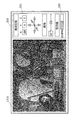
- FIG. 11 is a diagram illustrating an example of the GUI 300 in the initial state.
- the input image 121 is displayed. Further, the user can instruct conversion parameters (here, viewpoint position and angle of view) via the GUI 300.
- the GUI 300 includes objects 301 to 305.
- the object 301 is a text box 301x, 301y, 301z for displaying and inputting a value indicating the viewpoint position in each of the X-axis direction (horizontal direction), the Y-axis direction (vertical direction), and the Z-axis direction (depth direction).
- a value indicating the viewpoint position is used as a value indicating the viewpoint position.
- the user can change the viewpoint position of the currently displayed image (here, the input image 121) by inputting a value in the text boxes 301x to 301z.
- the object 302 has buttons 302x to 302z for changing the viewpoint position.
- the button 302x is a button for changing the viewpoint position in the positive or negative direction in the X-axis direction.
- the button 302y is a button for changing the viewpoint position in the positive or negative direction in the Y-axis direction.
- the button 302z is a button for changing the viewpoint position in a positive or negative direction in the Z-axis direction. The user can change the viewpoint position of the currently displayed image by pressing these buttons 302x to 302z.
- the object 303 has a text box for displaying and inputting a value indicating the angle of view.
- the user can change the angle of view of the currently displayed image by inputting a value in this text box.
- the object 304 has a slide bar for changing the angle of view.
- the user can change the angle of view of the currently displayed image by moving the slide bar left and right.
- the object 305 has text and an image for displaying information indicating the relationship between the blank value and the threshold value.
- the ratio of the blank value to the threshold is used as information indicating the relationship between the blank value and the threshold.
- the hatched area increases or decreases according to the ratio of the blank value to the threshold value.
- FIG. 12 is a diagram illustrating an example of a GUI that displays the converted image 131a generated based on the input conversion parameter.
- FIG. 13 is a diagram illustrating an example of a GUI that displays a converted image 131b (blank value> threshold value) generated based on the interpolation conversion parameter.
- the blank area is expressed in black.
- the parameter input unit 102 receives an input of a conversion parameter indicating “30” as the amount of change in the viewpoint position in the X-axis direction. Then, the converted image generation unit 117 generates a converted image 131a by performing projective conversion based on the received conversion parameter. The output unit 118 outputs the generated converted image 131a. Further, the output unit 118 outputs “130%” as information indicating the relationship between the blank value indicating the size of the blank area detected from the converted image 131 a by the blank area detection unit 104 and the threshold value.
- the converted image 131a is displayed and the object 305 is updated as shown in FIG.
- the blank value is larger than the threshold value, the following processing is further performed.
- the parameter calculation unit 116 calculates an interpolation conversion parameter by interpolating between the initial conversion parameter and the input conversion parameter.
- the parameter calculation unit 116 linearly interpolates between the viewpoint position indicated by the input conversion parameter and the viewpoint position indicated by the initial conversion parameter, thereby setting “25” as the change amount of the viewpoint position in the X-axis direction.
- the interpolation conversion parameter shown is calculated.
- the converted image generation unit 117 generates a converted image 131b by performing projective conversion based on the calculated interpolation conversion parameter.
- the output unit 118 outputs the generated converted image 131b. Further, the output unit 118 outputs “110%” as information indicating the relationship between the blank value indicating the size of the blank area detected from the converted image 131b by the blank area detection unit 104 and the threshold value.
- the converted image 131b is displayed, and the object 301 and the object 305 are updated. Again, since the blank value is still larger than the threshold value, the following processing is further performed.
- the parameter calculation unit 116 calculates an interpolation conversion parameter by interpolating between the initial conversion parameter and the input conversion parameter. Specifically, the parameter calculation unit 116 calculates an interpolation conversion parameter that is closer to the input conversion parameter than the previously calculated interpolation conversion parameter. Here, the parameter calculation unit 116 calculates an interpolation conversion parameter indicating “20” as the amount of change in the viewpoint position in the X-axis direction. Then, the converted image generation unit 117 generates a converted image 131c by performing projective conversion based on the calculated interpolation conversion parameter. The output unit 118 outputs the generated converted image 131c. Further, the output unit 118 outputs “100%” as information indicating the relationship between the blank value indicating the size of the blank area detected from the converted image 131 c by the blank area detection unit 104 and the threshold value.
- the converted image 131c is displayed, and the object 301 and the object 305 are updated.
- the process ends.
- the image processing apparatus 115 automatically calculates the interpolation conversion parameter closer to the initial conversion parameter than the input conversion parameter when the image quality of the converted image is greatly deteriorated. Can do. Therefore, the image processing apparatus 115 can suppress deterioration of the image quality of the converted image.
- the interpolation conversion parameter can be calculated so that the interpolation conversion parameter gradually approaches the initial conversion parameter. Therefore, the image processing apparatus 115 can automatically calculate conversion parameters so that the converted image satisfies a predetermined image quality. That is, the image processing apparatus 115 can suppress deterioration in the image quality of the converted image.
- the image processing apparatus 115 can sequentially output converted images generated based on the interpolation conversion parameters calculated as described above. Therefore, the image processing apparatus 115 can present to the user a manner in which the image quality of the converted image improves as an animation.
- the image processing apparatus 115 it is possible to present the degree of image quality degradation to the user. Therefore, the image processing apparatus 115 can improve user operability in a user interface for performing image processing.
- the pixel value in the blank area remains the initial value (black), but may be supplemented based on the pixel value in the vicinity of the blank area as in the second embodiment.
- the image processing apparatus 115 generates a converted image 131d by complementing the pixel values of the pixels in the blank area in the converted image 131c. Further, the image processing device 115 outputs the generated converted image 131d. Thereby, the image processing apparatus 115 can suppress deterioration in image quality due to the blank area.
- the parameter calculation unit 116 does not necessarily calculate the conversion parameter by interpolation as described above.
- the parameter input unit 102 may search for other conversion parameters that reduce the blank area using a general search algorithm. As a result, it is possible to automatically search for a converted image whose blank value is equal to or less than the threshold value.
- the image processing apparatus has been described based on the embodiments.
- the present invention is not limited to these embodiments. Unless it deviates from the gist of the present invention, one or more of the present invention may be implemented by various modifications conceived by those skilled in the art in this embodiment, or in a form constructed by combining components in different embodiments. Included within the scope of the embodiments.
- the blank value is the number of pixels constituting the blank area, but the blank value is not necessarily the number of pixels.
- the blank value may be a value weighted according to the position of the blank area.
- the blank value may be a value weighted so that the blank value of the blank area becomes larger as the position of the blank area is closer to the center position of the converted image.
- the blank area present at the center of the image has a greater influence on the image quality degradation than the blank area present at the edge of the image. Therefore, as described above, by using the blank value weighted so that the blank value of the blank area becomes larger as the position of the blank area is closer to the center position of the converted image, the image quality of the plurality of blank areas is degraded. Whether or not to output a converted image can be switched according to a blank area having a large influence on the image, and it is possible to suppress the output of a converted image with greatly deteriorated image quality.
- the blank value may be a value weighted according to the shape of the blank area.
- the blank value may be a value that is weighted so that the blank value of the blank area increases as the aspect ratio (aspect ratio) of the blank area decreases. That is, the blank value may be a value weighted so that the blank value of the blank area increases as the variation in the distance from the center of the blank area to the boundary line decreases. That is, the blank value may be a value weighted so that the blank value of the blank area becomes larger as the shape of the blank area is closer to a circle.
- a blank area having a smaller aspect ratio that is, having a shorter width and width
- a blank value weighted so that the blank value of the blank area becomes larger as the aspect ratio of the blank area becomes smaller a blank having a large influence on image quality deterioration among a plurality of blank areas. Whether or not to output a converted image can be switched depending on the region, and it is possible to suppress the output of a converted image with greatly deteriorated image quality.
- the processing is terminated as it is when the blank value is larger than the threshold value.
- the output unit 105 may perform the following processing.
- the output unit 105 may output information for requesting input of another conversion parameter when the blank value is greater than the threshold value.
- the image processing apparatus can request input of other conversion parameters when the image quality of the converted image is greatly deteriorated.
- the image processing apparatus can generate a converted image based on other conversion parameters, and can generate a converted image in which deterioration of image quality due to a blank area is suppressed.
- the output unit 105 may output information indicating that the converted image cannot be output when the blank value is larger than the threshold value. Thereby, for example, the user can recognize that a converted image based on the input conversion parameter is not output.
- the output unit 105 requests information for highlighting an object for receiving an instruction for initializing the conversion parameter from the user to input another conversion parameter. May be output as the information.
- initialization of the conversion parameter means resetting the conversion parameter to the conversion parameter corresponding to the input image.
- the object for receiving an instruction from the user is, for example, a GUI object such as a reset button.
- the information for highlighting is, for example, information for instructing blinking of the object, information for instructing to change the color of the object to a color with high attractiveness, or instructing to increase the size of the object. Information.
- the image processing apparatus can prompt the user to initialize the conversion parameter, and can suppress the deterioration of the image quality of the converted image. Also, the image processing apparatus can improve user operability.
- the output unit 105 may output the previously output converted image when the blank value is larger than the threshold value. Specifically, the output unit 105 may output a converted image that is output when the blank value is equal to or less than a threshold value, instead of the converted image 131a, for example, in the case shown in FIG. As a result, the image processing apparatus can prevent a converted image with degraded image quality from being output.
- FIG. 16 is a block diagram illustrating a functional configuration of a display device 200 according to a modification of the first, second, or third embodiment.
- the display device 200 is, for example, a television, a digital still camera, a digital video camera, a personal computer, or a mobile phone. As illustrated in FIG. 16, the display device 200 includes an image processing device 100, 110, or 115 and a display unit 201. Here, the image processing apparatus 100, 110, or 115 outputs the converted image to the display unit 201. When the converted image is acquired from the image processing apparatus 100, 110, or 115, the display unit 201 displays the converted image on the screen. Specifically, the display unit 201 displays a GUI as shown in FIGS. 11 to 14, for example.
- the converted image is a two-dimensional image, but may be a three-dimensional image. That is, the converted image generation unit may generate a three-dimensional image.
- the converted image generation unit may generate the converted image as one of the left-eye image and the right-eye image.
- the converted image generation unit may generate an image having a viewpoint position different from that of the converted image as the other of the left-eye image and the right-eye image.
- the display unit may three-dimensionally display the left-eye image and the right-eye image generated in this way.
- the blank area detection unit may detect a blank area in both the left-eye image and the right-eye image.
- the blank value is a statistical representative value (for example, the maximum value or the average value) of the value indicating the size of the blank area in the left-eye image and the value indicating the size of the blank area in the right-eye image. Etc.).
- the image processing apparatus 100 may include a system LSI having a data input unit 101, a parameter input unit 102, a converted image generation unit 103, a blank area detection unit 104, and an output unit 105.
- system LSI Large Scale Integration
- the system LSI is an ultra-multifunctional LSI manufactured by integrating a plurality of components on a single chip. Specifically, a microprocessor, a ROM (Read Only Memory), a RAM (Random Access Memory), etc. It is a computer system comprised including. A computer program is stored in the ROM. The system LSI achieves its functions by the microprocessor operating according to the computer program.
- system LSI may be called IC, LSI, super LSI, or ultra LSI depending on the degree of integration.
- method of circuit integration is not limited to LSI's, and implementation using dedicated circuitry or general purpose processors is also possible.
- An FPGA Field Programmable Gate Array
- reconfigurable processor that can reconfigure the connection and setting of circuit cells inside the LSI may be used.
- each component may be configured by dedicated hardware or may be realized by executing a software program suitable for each component.
- Each component may be realized by a program execution unit such as a CPU or a processor reading and executing a software program recorded on a recording medium such as a hard disk or a semiconductor memory.
- the software that realizes the image processing apparatus according to each of the above embodiments is the following program.
- this program is a data input step for receiving input of an input image, depth data indicating the depth of the input image, and imaging parameters of the input image, and parameters relating to projective transformation of the three-dimensional model.
- a conversion image that generates a conversion image by performing projective conversion based on the conversion parameter in a three-dimensional model obtained from a parameter input step that receives input of conversion parameters, the input image, the depth data, and the imaging parameters
- a blank area detecting step for detecting a blank area that is a set of blank pixels that are pixels in which no corresponding pixel exists in the input image in the converted image; and a blank value indicating a size of the blank area.
- Output threshold for outputting the converted image when Tsu to execute and-flops.
- It can be used as an image processing apparatus that can convert an input image using depth data, or a television, digital still camera, digital video camera, personal computer, or mobile phone equipped with the image processing apparatus.
Landscapes
- Engineering & Computer Science (AREA)
- Physics & Mathematics (AREA)
- Theoretical Computer Science (AREA)
- General Physics & Mathematics (AREA)
- Multimedia (AREA)
- Signal Processing (AREA)
- Computing Systems (AREA)
- Geometry (AREA)
- Computer Graphics (AREA)
- Computer Vision & Pattern Recognition (AREA)
- Image Processing (AREA)
- Testing, Inspecting, Measuring Of Stereoscopic Televisions And Televisions (AREA)
Abstract
Description
従来の方法では、変換画像の画質が大きく劣化する場合がある。例えば、射影変換により生成された変換画像内に、入力画像に対応する像が存在しない空白領域が発生する場合があり、このような場合に変換画像の画質が大きく劣化してしまう。
図1は、実施の形態1に係る画像処理装置の機能構成を示すブロック図である。この画像処理装置100は、データ入力部101と、パラメータ入力部102と、変換画像生成部103と、空白領域検出部104と、出力部105とを備える。




次に、実施の形態2について説明する。本実施の形態に係る画像処理装置は、変換画像内の空白領域を構成する画素の画素値を補完し、補完後の変換画像を出力する点が、実施の形態1に係る画像処理装置と主として異なる。
実施の形態3に係る画像処理装置は、空白値が閾値より大きい場合に他の変換パラメータを自動的に生成する。そして、実施の形態3に係る画像処理装置は、新たに生成された他の変換パラメータに基づいて新たに変換画像を生成する。以下に、本実施の形態に係る画像処理装置について図面を参照しながら具体的に説明する。
(CVPR 2007), Minneapolis, MN, June 2007.
(2)H. Hirschmuller and D. Scharstein. Evaluation of cost functions for stereo matching. In IEEE Computer Society Conference on Computer Vision and Pattern
Recognition (CVPR 2007), Minneapolis, MN, June 2007.
101 データ入力部
102 パラメータ入力部
103、117 変換画像生成部
104 空白領域検出部
105、118 出力部
111 補完部
116 パラメータ算出部
121 入力画像
122 深度データ
123 撮影パラメータ
124 変換パラメータ
131、131a、131b、131c、131d 変換画像
132 空白領域
200 表示装置
201 表示部
300 GUI
301、302、303、304、305 オブジェクト
301x、301y、301z テキストボックス
302x、302y、302z ボタン
Claims (15)
- 入力画像と、前記入力画像の深度を示す深度データと、前記入力画像の撮影パラメータとの入力を受け付けるデータ入力部と、
3次元モデルの射影変換に関するパラメータである変換パラメータの入力を受け付けるパラメータ入力部と、
前記入力画像と前記深度データと前記撮影パラメータとから得られる3次元モデルにおいて、前記変換パラメータに基づく射影変換を行うことにより、変換画像を生成する変換画像生成部と、
前記変換画像において、前記入力画像内に対応する画素が存在しない画素である空白画素の集合である空白領域を検出する空白領域検出部と、
前記空白領域の大きさを示す空白値が閾値以下である場合に、前記変換画像を出力する出力部とを備える
画像処理装置。 - 前記空白領域検出部は、互いに隣接する空白画素の集合が1つの空白領域となるように、複数の前記空白領域を検出し、
前記出力部は、複数の前記空白領域の各々の空白値のうちの最大の空白値が前記閾値以下である場合に、前記変換画像を出力する
請求項1に記載の画像処理装置。 - 前記空白値は、空白領域の位置が変換画像の中心位置に近いほど当該空白領域の空白値が大きくなるように重み付けされた値である
請求項1または2に記載の画像処理装置。 - 前記空白値は、空白領域の縦横比が小さいほど当該空白領域の空白値が大きくなるように重み付けされた値である
請求項1~3のいずれか1項に記載の画像処理装置。 - さらに、前記空白領域近傍の画素の画素値に基づいて、前記空白領域の画素の画素値を補完する補完部を備え、
前記出力部は、前記空白値が前記閾値以下である場合に、前記空白領域の画素の画素値が補完された前記変換画像を出力する
請求項1~4のいずれか1項に記載の画像処理装置。 - 前記パラメータ入力部は、前記入力画像に対する視点位置の変更指示を前記変換パラメータの入力としてユーザから受け付け、
前記変換画像生成部は、前記変換パラメータによって特定される視点位置に基づいて射影変換を行うことにより、前記変換画像を生成する
請求項1~5のいずれか1項に記載の画像処理装置。 - 前記出力部は、さらに、前記空白値が前記閾値より大きい場合に、他の変換パラメータの入力を要求するための情報を出力する
請求項1~6のいずれか1項に記載の画像処理装置。 - 前記出力部は、前記空白値が前記閾値より大きい場合に、前記変換パラメータを初期化する指示をユーザから受け付けるためのオブジェクトを強調表示するための情報を、前記他の変換パラメータの入力を要求するための情報として出力する
請求項7に記載の画像処理装置。 - 前記出力部は、さらに、前記空白値が前記閾値より大きい場合に、前に出力された変換画像を出力する
請求項1~8のいずれか1項に記載の画像処理装置。 - 前記画像処理装置は、さらに、
前記空白値が前記閾値より大きい場合に、前記入力画像に対応する変換パラメータと、前記パラメータ入力部によって受け付けられた変換パラメータとの間を補間することにより、補間変換パラメータを算出するパラメータ算出部を備え、
前記変換画像生成部は、さらに、算出された前記補間変換パラメータに基づく射影変換を行うことにより、新たに変換画像を生成する
請求項1~6のいずれか1項に記載の画像処理装置。 - 前記パラメータ算出部は、前記空白値が前記閾値以下になるまで、前記補間変換パラメータが、前記パラメータ入力部によって受け付けられた変換パラメータから前記入力画像に対応する変換パラメータへ徐々に近付くように、前記補間変換パラメータを順に算出し、
前記変換画像生成部は、前記補間変換パラメータに基づいて、前記変換画像を順に生成し、
前記出力部は、前記変換画像を順に出力する
請求項10に記載の画像処理装置。 - 前記出力部は、さらに、前記空白値と前記閾値との関係を示す情報を出力する
請求項1~11のいずれか1項に記載の画像処理装置。 - 前記画像処理装置は、集積回路として構成されている
請求項1~12のいずれか1項に記載の画像処理装置。 - 入力画像と、前記入力画像の深度を示す深度データと、前記入力画像の撮影パラメータとの入力を受け付けるデータ入力ステップと、
3次元モデルの射影変換に関するパラメータである変換パラメータの入力を受け付けるパラメータ入力ステップと、
前記入力画像と前記深度データと前記撮影パラメータとから得られる3次元モデルにおいて、前記変換パラメータに基づく射影変換を行うことにより、変換画像を生成する変換画像生成ステップと、
前記変換画像において、前記入力画像内に対応する画素が存在しない画素である空白画素の集合である空白領域を検出する空白領域検出ステップと、
前記空白領域の大きさを示す空白値が閾値以下である場合に、前記変換画像を出力する出力ステップとを含む
画像処理方法。 - 請求項14に記載の画像処理方法をコンピュータに実行させるためのプログラム。
Priority Applications (3)
| Application Number | Priority Date | Filing Date | Title |
|---|---|---|---|
| US13/814,259 US9082183B2 (en) | 2011-06-08 | 2012-06-05 | Image processing device and image processing method |
| CN201280002319.7A CN103053169B (zh) | 2011-06-08 | 2012-06-05 | 图像处理装置及图像处理方法 |
| JP2012536622A JP5927541B2 (ja) | 2011-06-08 | 2012-06-05 | 画像処理装置および画像処理方法 |
Applications Claiming Priority (2)
| Application Number | Priority Date | Filing Date | Title |
|---|---|---|---|
| JP2011-128651 | 2011-06-08 | ||
| JP2011128651 | 2011-06-08 |
Publications (1)
| Publication Number | Publication Date |
|---|---|
| WO2012169174A1 true WO2012169174A1 (ja) | 2012-12-13 |
Family
ID=47295759
Family Applications (1)
| Application Number | Title | Priority Date | Filing Date |
|---|---|---|---|
| PCT/JP2012/003682 Ceased WO2012169174A1 (ja) | 2011-06-08 | 2012-06-05 | 画像処理装置および画像処理方法 |
Country Status (4)
| Country | Link |
|---|---|
| US (1) | US9082183B2 (ja) |
| JP (1) | JP5927541B2 (ja) |
| CN (1) | CN103053169B (ja) |
| WO (1) | WO2012169174A1 (ja) |
Cited By (2)
| Publication number | Priority date | Publication date | Assignee | Title |
|---|---|---|---|---|
| CN103870103A (zh) * | 2012-12-14 | 2014-06-18 | 联想(北京)有限公司 | 信息处理的方法及电子设备 |
| WO2025204322A1 (ja) * | 2024-03-29 | 2025-10-02 | ソニーグループ株式会社 | 画像処理装置、画像処理システム、画像処理方法およびプログラム |
Families Citing this family (5)
| Publication number | Priority date | Publication date | Assignee | Title |
|---|---|---|---|---|
| JP6589636B2 (ja) * | 2013-11-06 | 2019-10-16 | 凸版印刷株式会社 | 3次元形状計測装置、3次元形状計測方法及び3次元形状計測プログラム |
| US20200219278A1 (en) * | 2017-09-27 | 2020-07-09 | Sharp Kabushiki Kaisha | Video generating apparatus, video capturing apparatus, video capturing system, video generation method, control program, and recording medium |
| CN110675384B (zh) * | 2019-09-24 | 2022-06-07 | 广东博智林机器人有限公司 | 图像处理方法及装置 |
| JP7695619B2 (ja) * | 2020-03-12 | 2025-06-19 | ソニーグループ株式会社 | 画像処理装置および方法、並びにプログラム |
| CN115830612A (zh) * | 2022-12-20 | 2023-03-21 | 北京嘉和海森健康科技有限公司 | 一种ocr训练数据的生成方法、装置、设备及存储介质 |
Citations (4)
| Publication number | Priority date | Publication date | Assignee | Title |
|---|---|---|---|---|
| JPH11351865A (ja) * | 1998-06-11 | 1999-12-24 | Topcon Corp | 画像計測処理方法並びに装置及び画像計測処理プログラムを記録した記録媒体 |
| JP2010250452A (ja) * | 2009-04-14 | 2010-11-04 | Tokyo Univ Of Science | 任意視点画像合成装置 |
| JP2011044828A (ja) * | 2009-08-19 | 2011-03-03 | Fujifilm Corp | 立体画像生成装置、立体画像プリント装置、及び立体画像生成方法 |
| JP2011081605A (ja) * | 2009-10-07 | 2011-04-21 | Fujifilm Corp | 画像処理装置、方法及びプログラム |
Family Cites Families (35)
| Publication number | Priority date | Publication date | Assignee | Title |
|---|---|---|---|---|
| US5280280A (en) * | 1991-05-24 | 1994-01-18 | Robert Hotto | DC integrating display driver employing pixel status memories |
| JP3059590B2 (ja) * | 1992-09-30 | 2000-07-04 | 富士通株式会社 | 立体表示方法及び装置 |
| US20020114521A1 (en) * | 1993-10-14 | 2002-08-22 | Tooru Fujii | Image processing device and method for identifying an input image and copier including same |
| US6384859B1 (en) * | 1995-03-29 | 2002-05-07 | Sanyo Electric Co., Ltd. | Methods for creating an image for a three-dimensional display, for calculating depth information and for image processing using the depth information |
| US5923820A (en) * | 1997-01-23 | 1999-07-13 | Lexmark International, Inc. | Method and apparatus for compacting swath data for printers |
| US6442293B1 (en) | 1998-06-11 | 2002-08-27 | Kabushiki Kaisha Topcon | Image forming apparatus, image forming method and computer-readable storage medium having an image forming program |
| US6633685B1 (en) * | 1998-08-05 | 2003-10-14 | Canon Kabushiki Kaisha | Method, apparatus, and storage media for image processing |
| US6631206B1 (en) * | 1999-08-30 | 2003-10-07 | University Of Washington | Image filtering in HSI color space |
| US20020126910A1 (en) * | 2001-01-02 | 2002-09-12 | Eastman Kodak Company | Method of calculating noise from multiple digital images utilizing common noise characteristics |
| JP3505575B2 (ja) | 2001-03-23 | 2004-03-08 | 独立行政法人産業技術総合研究所 | デジタルミラー装置 |
| US7031548B2 (en) * | 2001-10-04 | 2006-04-18 | Hewlett-Packard Development Company, L.P. | Method and apparatus for filtering noise from a digital image |
| JP3945279B2 (ja) * | 2002-03-15 | 2007-07-18 | ソニー株式会社 | 障害物認識装置、障害物認識方法、及び障害物認識プログラム並びに移動型ロボット装置 |
| US20050196070A1 (en) * | 2003-02-28 | 2005-09-08 | Fujitsu Limited | Image combine apparatus and image combining method |
| US8593542B2 (en) * | 2005-12-27 | 2013-11-26 | DigitalOptics Corporation Europe Limited | Foreground/background separation using reference images |
| US7542034B2 (en) * | 2004-09-23 | 2009-06-02 | Conversion Works, Inc. | System and method for processing video images |
| US8320641B2 (en) * | 2004-10-28 | 2012-11-27 | DigitalOptics Corporation Europe Limited | Method and apparatus for red-eye detection using preview or other reference images |
| US8164594B2 (en) * | 2006-05-23 | 2012-04-24 | Panasonic Corporation | Image processing device, image processing method, program, storage medium and integrated circuit |
| WO2007148219A2 (en) * | 2006-06-23 | 2007-12-27 | Imax Corporation | Methods and systems for converting 2d motion pictures for stereoscopic 3d exhibition |
| TWI356364B (en) * | 2006-10-17 | 2012-01-11 | Chimei Innolux Corp | Liquid crystal display device and image display me |
| US7968831B2 (en) * | 2007-06-12 | 2011-06-28 | The Boeing Company | Systems and methods for optimizing the aimpoint for a missile |
| JP2009005008A (ja) * | 2007-06-20 | 2009-01-08 | Olympus Corp | 画像データ処理装置及び画像データ処理方法 |
| US8005319B2 (en) * | 2007-09-24 | 2011-08-23 | Arcsoft, Inc. | Method for digitally magnifying images |
| US8073190B2 (en) * | 2007-11-16 | 2011-12-06 | Sportvision, Inc. | 3D textured objects for virtual viewpoint animations |
| CN100589530C (zh) * | 2008-10-20 | 2010-02-10 | 四川虹微技术有限公司 | 一种用于视图合成的空洞填充方法 |
| CN101610423B (zh) * | 2009-07-13 | 2010-09-08 | 清华大学 | 一种渲染图像的方法和装置 |
| CN101695139B (zh) * | 2009-10-14 | 2011-08-17 | 宁波大学 | 一种基于可分级块的虚拟视点图像绘制方法 |
| US8593483B2 (en) * | 2009-10-20 | 2013-11-26 | Apple Inc. | Temporal filtering techniques for image signal processing |
| JP5560721B2 (ja) * | 2010-01-12 | 2014-07-30 | セイコーエプソン株式会社 | 画像処理装置、画像表示システム、及び画像処理方法 |
| JP2011211474A (ja) * | 2010-03-30 | 2011-10-20 | Sony Corp | 画像処理装置および画像信号処理方法 |
| US9305372B2 (en) * | 2010-07-26 | 2016-04-05 | Agency For Science, Technology And Research | Method and device for image processing |
| EP2544149A4 (en) * | 2011-03-22 | 2014-11-19 | Morpho Inc | DEVICE FOR DETERMINING MOTIVATED BODIES, METHOD FOR DETECTING MOTIVATED BODIES, PROGRAM FOR DETECTING MOTIVATED BODIES, DEVICE FOR MONITORING MOTIVATED BODIES, METHOD FOR TRACKING MOVING BODIES AND PROGRAM FOR TRACKING MOTIVATED BODIES |
| JP5799634B2 (ja) * | 2011-07-22 | 2015-10-28 | 株式会社リコー | 画像処理装置、画像処理システム |
| JP5891722B2 (ja) * | 2011-11-10 | 2016-03-23 | セイコーエプソン株式会社 | 制御装置、電気光学装置、電子機器および制御方法 |
| US8941750B2 (en) * | 2011-12-27 | 2015-01-27 | Casio Computer Co., Ltd. | Image processing device for generating reconstruction image, image generating method, and storage medium |
| US9105078B2 (en) * | 2012-05-31 | 2015-08-11 | Apple Inc. | Systems and methods for local tone mapping |
-
2012
- 2012-06-05 WO PCT/JP2012/003682 patent/WO2012169174A1/ja not_active Ceased
- 2012-06-05 CN CN201280002319.7A patent/CN103053169B/zh not_active Expired - Fee Related
- 2012-06-05 JP JP2012536622A patent/JP5927541B2/ja not_active Expired - Fee Related
- 2012-06-05 US US13/814,259 patent/US9082183B2/en not_active Expired - Fee Related
Patent Citations (4)
| Publication number | Priority date | Publication date | Assignee | Title |
|---|---|---|---|---|
| JPH11351865A (ja) * | 1998-06-11 | 1999-12-24 | Topcon Corp | 画像計測処理方法並びに装置及び画像計測処理プログラムを記録した記録媒体 |
| JP2010250452A (ja) * | 2009-04-14 | 2010-11-04 | Tokyo Univ Of Science | 任意視点画像合成装置 |
| JP2011044828A (ja) * | 2009-08-19 | 2011-03-03 | Fujifilm Corp | 立体画像生成装置、立体画像プリント装置、及び立体画像生成方法 |
| JP2011081605A (ja) * | 2009-10-07 | 2011-04-21 | Fujifilm Corp | 画像処理装置、方法及びプログラム |
Cited By (2)
| Publication number | Priority date | Publication date | Assignee | Title |
|---|---|---|---|---|
| CN103870103A (zh) * | 2012-12-14 | 2014-06-18 | 联想(北京)有限公司 | 信息处理的方法及电子设备 |
| WO2025204322A1 (ja) * | 2024-03-29 | 2025-10-02 | ソニーグループ株式会社 | 画像処理装置、画像処理システム、画像処理方法およびプログラム |
Also Published As
| Publication number | Publication date |
|---|---|
| US9082183B2 (en) | 2015-07-14 |
| JP5927541B2 (ja) | 2016-06-01 |
| JPWO2012169174A1 (ja) | 2015-02-23 |
| US20130136342A1 (en) | 2013-05-30 |
| CN103053169B (zh) | 2016-03-16 |
| CN103053169A (zh) | 2013-04-17 |
Similar Documents
| Publication | Publication Date | Title |
|---|---|---|
| JP5927541B2 (ja) | 画像処理装置および画像処理方法 | |
| CN109816766B (zh) | 图像处理装置、图像处理方法及存储介质 | |
| JP5156837B2 (ja) | 領域ベースのフィルタリングを使用する奥行マップ抽出のためのシステムおよび方法 | |
| CN107409166B (zh) | 摇摄镜头的自动生成 | |
| CN104012088B (zh) | 图像处理装置以及图像处理方法 | |
| JP5887267B2 (ja) | 3次元画像補間装置、3次元撮像装置および3次元画像補間方法 | |
| JP6371553B2 (ja) | 映像表示装置および映像表示システム | |
| US9412151B2 (en) | Image processing apparatus and image processing method | |
| US20180098047A1 (en) | Imaging system, image processing apparatus, image processing method, and storage medium | |
| US20150097827A1 (en) | Target Region Fill Utilizing Transformations | |
| US20150177062A1 (en) | Information processing apparatus, information processing method, and storage medium | |
| EP3189493B1 (en) | Depth map based perspective correction in digital photos | |
| CN103238168A (zh) | 图像处理装置、图像处理方法及图像处理程序 | |
| EP4064193A1 (en) | Real-time omnidirectional stereo matching using multi-view fisheye lenses | |
| WO2023199583A1 (ja) | ビューワ制御方法及び情報処理装置 | |
| US12548108B2 (en) | Image processing apparatus, image processing method, and storage medium that generate a perspective projection image from a wide-angle image | |
| JP5926626B2 (ja) | 画像処理装置及びその制御方法、プログラム | |
| JP6320165B2 (ja) | 画像処理装置及びその制御方法、並びにプログラム | |
| JP6351364B2 (ja) | 情報処理装置、情報処理方法およびプログラム | |
| JP2019517688A (ja) | 二枚の表示画像間の移行を割り出すための方法及び装置、並びに、車両 | |
| JP2016001386A (ja) | 画像生成方法、画像生成装置、コンピュータプログラム及び記録媒体 | |
| US20240281939A1 (en) | Image processing apparatus for applying image processing to perspective projection image, image processing method and non-transitory computer-readable storage medium | |
| CN110264406A (zh) | 图像处理装置及图像处理的方法 | |
| CN109151299B (zh) | 一种用于对焦的方法和装置 | |
| CN119814945A (zh) | 影像合成方法及影像合成系统 |
Legal Events
| Date | Code | Title | Description |
|---|---|---|---|
| WWE | Wipo information: entry into national phase |
Ref document number: 201280002319.7 Country of ref document: CN |
|
| ENP | Entry into the national phase |
Ref document number: 2012536622 Country of ref document: JP Kind code of ref document: A |
|
| WWE | Wipo information: entry into national phase |
Ref document number: 13814259 Country of ref document: US |
|
| 121 | Ep: the epo has been informed by wipo that ep was designated in this application |
Ref document number: 12796972 Country of ref document: EP Kind code of ref document: A1 |
|
| NENP | Non-entry into the national phase |
Ref country code: DE |
|
| 122 | Ep: pct application non-entry in european phase |
Ref document number: 12796972 Country of ref document: EP Kind code of ref document: A1 |