WO2012169178A1 - Dispositif et procédé de génération d'images photo-acoustiques - Google Patents
Dispositif et procédé de génération d'images photo-acoustiques Download PDFInfo
- Publication number
- WO2012169178A1 WO2012169178A1 PCT/JP2012/003686 JP2012003686W WO2012169178A1 WO 2012169178 A1 WO2012169178 A1 WO 2012169178A1 JP 2012003686 W JP2012003686 W JP 2012003686W WO 2012169178 A1 WO2012169178 A1 WO 2012169178A1
- Authority
- WO
- WIPO (PCT)
- Prior art keywords
- light
- photoacoustic
- photoacoustic image
- light emitting
- signal
- Prior art date
- Legal status (The legal status is an assumption and is not a legal conclusion. Google has not performed a legal analysis and makes no representation as to the accuracy of the status listed.)
- Ceased
Links
Images






Classifications
-
- A—HUMAN NECESSITIES
- A61—MEDICAL OR VETERINARY SCIENCE; HYGIENE
- A61B—DIAGNOSIS; SURGERY; IDENTIFICATION
- A61B5/00—Measuring for diagnostic purposes; Identification of persons
- A61B5/06—Devices, other than using radiation, for detecting or locating foreign bodies ; Determining position of diagnostic devices within or on the body of the patient
-
- A—HUMAN NECESSITIES
- A61—MEDICAL OR VETERINARY SCIENCE; HYGIENE
- A61B—DIAGNOSIS; SURGERY; IDENTIFICATION
- A61B5/00—Measuring for diagnostic purposes; Identification of persons
- A61B5/0093—Detecting, measuring or recording by applying one single type of energy and measuring its conversion into another type of energy
- A61B5/0095—Detecting, measuring or recording by applying one single type of energy and measuring its conversion into another type of energy by applying light and detecting acoustic waves, i.e. photoacoustic measurements
-
- A—HUMAN NECESSITIES
- A61—MEDICAL OR VETERINARY SCIENCE; HYGIENE
- A61B—DIAGNOSIS; SURGERY; IDENTIFICATION
- A61B5/00—Measuring for diagnostic purposes; Identification of persons
- A61B5/06—Devices, other than using radiation, for detecting or locating foreign bodies ; Determining position of diagnostic devices within or on the body of the patient
- A61B5/061—Determining position of a probe within the body employing means separate from the probe, e.g. sensing internal probe position employing impedance electrodes on the surface of the body
-
- A—HUMAN NECESSITIES
- A61—MEDICAL OR VETERINARY SCIENCE; HYGIENE
- A61B—DIAGNOSIS; SURGERY; IDENTIFICATION
- A61B5/00—Measuring for diagnostic purposes; Identification of persons
- A61B5/68—Arrangements of detecting, measuring or recording means, e.g. sensors, in relation to patient
- A61B5/6846—Arrangements of detecting, measuring or recording means, e.g. sensors, in relation to patient specially adapted to be brought in contact with an internal body part, i.e. invasive
- A61B5/6847—Arrangements of detecting, measuring or recording means, e.g. sensors, in relation to patient specially adapted to be brought in contact with an internal body part, i.e. invasive mounted on an invasive device
- A61B5/6848—Needles
Definitions
- the present invention relates to a photoacoustic image generation apparatus and method, and more specifically, photoacoustics that generate a photoacoustic image by irradiating a subject with laser light and detecting ultrasonic waves generated in the subject by the laser light irradiation.
- the present invention relates to an image generation apparatus and method.
- An ultrasonic inspection method is known as a kind of image inspection method capable of non-invasively examining the state inside a living body.
- an ultrasonic probe capable of transmitting and receiving ultrasonic waves is used.
- the ultrasonic waves travel inside the living body and are reflected at the tissue interface.
- the internal state can be imaged.
- photoacoustic imaging in which the inside of a living body is imaged using the photoacoustic effect.
- a living body is irradiated with pulsed laser light such as a laser pulse. Inside the living body, the living tissue absorbs the energy of the pulsed laser light, and ultrasonic waves (photoacoustic signals) are generated by adiabatic expansion due to the energy.
- ultrasonic waves photoacoustic signals
- Patent Document 1 refers to a combination of biological information imaging using photoacoustics and treatment using a puncture needle.
- a photoacoustic image is generated, and the image is observed to find an affected part such as a tumor or a part suspected of being affected.
- a puncture needle such as an injection needle or a cytodiagnosis needle is used to collect cells or inject into the affected part.
- puncture can be performed while observing an affected area using a photoacoustic image.
- an object of the present invention is to provide a photoacoustic image generation apparatus and method that can confirm the position of a puncture needle on a photoacoustic image.
- the present invention provides a light source that emits light, light irradiation means that irradiates light from the light source toward the subject, and a puncture needle that includes a light emitting unit that emits light from the light source. Based on the photoacoustic signal, an ultrasonic probe that detects a photoacoustic signal generated when the light absorber in the subject absorbs the light emitted from the light irradiation means and the light emitted from the light emitting unit.
- a photoacoustic image generation apparatus comprising image generation means for generating a photoacoustic image.
- the puncture needle has a light emitting portion at least at the tip thereof.
- the light emitting part can be composed of a light guide member formed so that its thickness decreases toward the tip of the puncture needle.
- the puncture needle may have a plurality of light emitting units arranged at positions separated from each other.
- at least one of the plurality of light emitting units may be configured by a portion where the core is exposed at an intermediate point of the optical fiber that guides light from the light source.
- the light irradiation from the light irradiation means and the light emission from the light emitting section are performed simultaneously, and the ultrasonic probe is emitted from the light emitting section and the photoacoustic signal resulting from the light emitted from the light irradiation means. It is good also as detecting simultaneously the photoacoustic signal resulting from light.
- the light irradiation from the light irradiation means and the light emission from the light emitting unit are separately performed, and the image generation means performs the first based on the photoacoustic signal caused by the light irradiated from the light irradiation means.
- the light source may emit light having a plurality of different wavelengths.
- the image generation means may generate a photoacoustic image based on the magnitude relationship of the signal intensity of the photoacoustic signal detected when the light of each wavelength is irradiated.
- the image generation means may have a deconvolution means for deconvolution of a differential waveform of light irradiated to the subject from the photoacoustic signal.
- the present invention also includes a step of irradiating light from the light irradiation means toward the subject, a step of irradiating the subject from the light emitting portion of the puncture needle having the light emitting portion, and a light absorber in the subject. Detecting a photoacoustic signal generated by absorbing the light emitted from the light irradiating means and the light emitted from the light emitting unit, and generating a photoacoustic image based on the photoacoustic signal.
- a photoacoustic image generation method characterized by the above is provided.
- the step of irradiating light from the light irradiating unit and the step of irradiating light from the light emitting unit are performed simultaneously, and the step of detecting the photoacoustic signal is performed by the light irradiating unit You may detect simultaneously the photoacoustic signal resulting from light and the photoacoustic signal resulting from the light radiate
- the light irradiating means is caused by the light irradiated from the light irradiating means.
- the first step is based on the photoacoustic signal caused by the light emitted from the light irradiation unit.
- a second photoacoustic image is generated based on a photoacoustic signal resulting from light emitted from the light emitting unit, and the first photoacoustic image and the second photoacoustic image are combined. May be.
- a light emitting unit is provided on the puncture needle, and the subject is irradiated with light from the light emitting unit.
- the light emitted from the light emitting unit is absorbed in the vicinity of the puncture needle, and a photoacoustic signal is generated in the vicinity of the puncture needle.
- the side view which shows the external appearance of a probe.
- the front view which shows the external appearance of a probe.
- the figure which shows the structural example for obtaining the two light emission parts shown in FIG. The figure which shows the illumination range of the light irradiation part at the time of providing two light emission parts, and the illumination range of a light emission part.
- FIG. 1 shows a photoacoustic image generation apparatus according to a first embodiment of the present invention.
- a photoacoustic image generation apparatus (photoacoustic image diagnostic apparatus) 10 includes a probe (ultrasonic probe) 11, an ultrasonic unit 12, and a laser unit (light source) 13.
- the laser unit 13 generates laser light that irradiates a subject such as a living tissue.
- the wavelength of the laser light may be appropriately set according to the biological tissue to be observed.
- the laser light emitted from the laser unit 13 is guided to the probe 11 and the puncture needle 15 using light guide means such as an optical fiber.
- the probe 11 is configured as an ultrasonic probe for an endoscope, for example.
- the probe 11 has light irradiation means for irradiating the subject with laser light guided to the probe 11.
- the probe 11 detects a photoacoustic signal generated by absorbing the laser beam irradiated by the light absorber in the subject.
- the probe 11 has, for example, a plurality of ultrasonic transducers arranged one-dimensionally.
- the light irradiating means does not need to be provided on the probe 11 and may be irradiated with laser light from a place other than the probe 11.
- the puncture needle 15 is a needle that is punctured into the subject.
- the puncture needle 15 has a light emitting unit 16 that emits laser light.
- the laser light emitted from the light emitting unit 16 is irradiated to a living tissue or the like in the subject.
- the illumination range of the light emitting unit 16 is narrower than the illumination range (light irradiation range) of the light irradiation means provided in the probe 11.
- the amount of light and power of the laser light emitted from the light emitting unit 16 is the laser light emitted from the light irradiation unit. It may be lower than the amount of light and power.
- the ultrasonic unit 12 includes a receiving circuit 21, AD conversion means 22, image generation means 23, and control means 24.
- the receiving circuit 21 receives photoacoustic signals detected by a plurality of ultrasonic transducers included in the probe 11.
- the AD conversion means 22 converts the photoacoustic signal received by the receiving circuit 21 into a digital signal.
- the AD converter 22 samples the photoacoustic signal at a predetermined sampling period based on, for example, a predetermined sampling clock signal input from the outside.
- the image generation means 23 generates a photoacoustic image based on the photoacoustic signal detected by the probe 11.
- the generation of the photoacoustic image includes, for example, image reconstruction such as phase matching addition, detection, logarithmic conversion, and the like.
- the image display unit 14 displays the photoacoustic image generated by the image generation unit 23 on a display monitor or the like.
- the control unit 24 controls each part in the ultrasonic unit 12. For example, the control unit 24 sends a laser oscillation trigger signal to the laser unit 13 to emit laser light from the laser unit 13.
- a sampling trigger signal is sent to the AD conversion means 22 in accordance with the laser light irradiation to control the sampling start timing of the photoacoustic signal.
- FIG. 2A and 2B show the appearance of the probe 11.
- FIG. FIG. 2A is a side view of the probe 11, and
- FIG. 2B is a front view of the probe 11.
- the probe 11 includes, for example, light irradiation means (light irradiation units) 32 on both sides of a plurality of one-dimensionally arranged ultrasonic transducers 33 when viewed from the front (FIG. 2B).
- the light irradiation unit 32 irradiates the subject with laser light guided from the laser unit 13 using the optical fiber 31 (FIG. 2A).
- the light irradiation part 32 is comprised as a surface light source, for example.
- the light irradiation range (illumination range) of the light irradiation unit 32 corresponds to the generation range of the photoacoustic image.
- a blood vessel or a lesioned part in the subject absorbs the laser beam emitted from the light irradiation unit 32 and generates a photoacoustic signal.
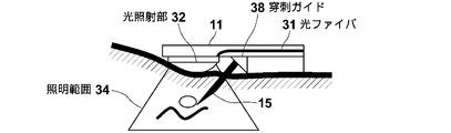
- the probe 11 has a puncture guide 38 for guiding the puncture needle 15.
- the puncture needle 15 is guided by the puncture guide 38 and punctured into the subject at a predetermined angle.
- FIG. 2A shows a state where the puncture needle 15 is punctured within the illumination range 34.
- the laser beam guided using the optical fiber 31 is also emitted from the light emitting portion 16 of the puncture needle 15.
- the light emitted from the light emitting unit 16 is absorbed by, for example, a component such as blood contained in the biological tissue of the subject, and a photoacoustic signal is generated from that portion.
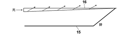
- FIG. 3 shows a configuration example of the light emitting unit 16.
- the light emitting unit 16 is configured as, for example, a linear light source.
- the light emitting unit 16 is configured by a light guide member formed so that the thickness decreases toward the distal end direction (light traveling direction) of the puncture needle 15, for example.
- it can be configured with a tapered fiber core whose thickness decreases toward the distal end of the puncture needle 15.
- the tapered shape may be formed by polishing or the like.
- the light emitting unit 16 does not need to illuminate a wide range because the light emitting unit 16 only needs to irradiate the living tissue near the puncture needle with the laser light from the light emitting unit 16.
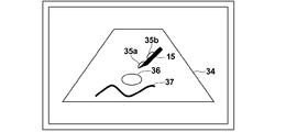
- FIG. 4 shows the illumination range of the light irradiation unit 32 (FIG. 1) and the illumination range of the light emitting unit 16 of the puncture needle 15.
- the laser beam is irradiated.
- the probe 11 detects a photoacoustic signal generated when the light absorber in the subject absorbs the laser light emitted from the light irradiation unit 32 and the laser light emitted from the light emitting unit 16 of the puncture needle 15.
- the image generation unit 23 generates a photoacoustic image based on the detected photoacoustic signal.
- the laser beam irradiation from the light irradiation unit 32 and the laser beam irradiation from the light emitting unit 16 of the puncture needle 15 are performed separately.
- laser light irradiation is first performed from the light irradiation unit 32 to detect a photoacoustic signal, and then laser light irradiation is performed from the light emitting unit 16 of the puncture needle 15 to detect the photoacoustic signal.
- the image generation unit 23 generates a first photoacoustic image based on the photoacoustic signal resulting from the laser light emitted from the light irradiation unit 32.
- a 2nd photoacoustic image is produced
- the lesion 36 and the blood vessel 37 in the illumination range 34 can be imaged by the generated first photoacoustic image. Further, since the light emitting unit 16 of the puncture needle 15 emits laser light only in the vicinity of the puncture needle 15, in the second photoacoustic image, a photoacoustic signal is linearly formed according to the position and direction of the puncture needle. The part to be detected appears. The user observes the synthesized photoacoustic image and searches for the boundary between the strong and weak portions of the photoacoustic signal appearing in a straight line, thereby specifying the position of the puncture needle 15 in the photoacoustic image. can do.
- the light emission part 16 does not necessarily need to be provided over the whole puncture needle 15, At least the front-end
- a laser beam may be guided to the tip of the puncture needle 15 using a thin optical fiber or the like, and a light emitting unit may be provided at the tip of the puncture needle 15.
- the optical fiber that guides the laser beam to the needle tip may pass through the inside of the puncture needle 15 or may be arranged outside the puncture needle 15.
- FIG. 5 shows an example in which the light emitting unit 16 is provided at the tip of the puncture needle 15.
- FIG. 6 shows an illumination range 34 of the light irradiation unit 32 and an illumination range 35 of the light emitting unit 16 when the light emitting unit is provided at the tip of the puncture needle.
- the length of the light emitting unit 16 is shortened in the length direction of the puncture needle 15, and the illumination range 35 is narrower than in the case of FIG.
- the position of the tip of the puncture needle 15 can be specified in the photoacoustic image.
- the light-emitting part 16 provided in the puncture needle 15 is not restricted to one, It is good also as providing the several light-emitting part 16 arrange
- FIG. 7 shows an example in which two light emitting portions 16 are provided on the puncture needle 15.
- the puncture needle 15 has a light emitting portion 16b at an intermediate portion in addition to the light emitting portion 16a at the tip portion.
- FIG. 8 shows a configuration example for obtaining the two light emitting units 16a and 16b shown in FIG.
- the light emitting portion 16b in the intermediate portion of the puncture needle 15 can be realized by partially peeling off the optical fiber cladding 42 to expose the core 41 and further polishing a part of the core 41.
- the light emitting portion 16a at the tip can be realized by exposing the core 41.
- FIG. 9 shows the illumination range of the light irradiation unit 32 and the illumination range of the light emitting unit 16 when two light emitting units are provided.
- An illumination range 35a and an illumination range 35b are formed corresponding to the light emitting portions 16a and 16b of the puncture needle 15.
- a photoacoustic signal is detected from the vicinity of the puncture needle 15 in each of the illumination range 35a and the illumination range 35b.
- the position connecting the portions where the two photoacoustic signals are detected can be detected as the position of the puncture needle.
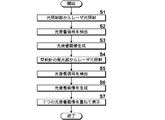
- FIG. 10 shows the operation procedure.
- the control means 24 of the ultrasonic unit 12 sends a laser oscillation trigger signal to the laser unit 13.
- the laser unit 13 Upon receiving the laser oscillation trigger signal, the laser unit 13 starts laser oscillation and emits pulsed laser light.
- the subject is irradiated with the pulse laser beam emitted from the laser unit 13 from the light irradiation unit 32 (FIG. 2A) of the probe 11 (step S1).
- the probe 11 detects a photoacoustic signal generated in the subject by the laser beam irradiation from the light irradiation unit 32 (step S2).
- the AD converter 22 receives the photoacoustic signal via the receiving circuit 21 and samples the photoacoustic signal.
- the image generation means 23 generates a first photoacoustic image based on the sampled photoacoustic signal (step S3).
- step S4 laser light irradiation is performed from the light emitting portion 16 of the puncture needle 15 (step S4).
- the probe 11 detects a photoacoustic signal generated in the subject by the irradiation of the laser light from the light emitting unit 16.
- Step S5 The AD converter 22 receives the photoacoustic signal via the receiving circuit 21 and samples the photoacoustic signal.
- the image generation means 23 generates a second photoacoustic image based on the sampled photoacoustic signal (step S6).
- the image generation means 23 synthesizes and outputs the generated first and second photoacoustic images.
- the image display means 14 displays the synthesized photoacoustic image (step S7). Instead of performing image generation by the image generation unit 23, the image display unit 14 may display the first and second photoacoustic images in a superimposed manner.
- the puncture needle 15 is provided with a light emitting unit 16 and laser light is emitted from the light emitting unit 16.
- the laser light emitted from the light emitting unit 16 is absorbed in the vicinity of the puncture needle 15, and a photoacoustic signal is generated in the vicinity of the puncture needle 15.
- a photoacoustic image By generating a photoacoustic image based on such a photoacoustic signal, the position of the puncture needle 15 and the like can be confirmed on the photoacoustic image.
- a photoacoustic image (first photoacoustic image) generated by irradiating laser light from the light irradiation unit 32 and a photoacoustic image (second photon) generated by irradiating laser light from the light emitting unit 16 of the puncture needle 15.
- first photoacoustic image generated by irradiating laser light from the light irradiation unit 32
- second photon generated by irradiating laser light from the light emitting unit 16 of the puncture needle 15.
- the subject is irradiated with light of a plurality of wavelengths, and a photoacoustic signal when the light of each wavelength is irradiated is detected.
- functional imaging is performed by using the photoacoustic signal when light of a plurality of wavelengths is irradiated, and utilizing the fact that the light absorption characteristics of each light absorber differ depending on the wavelength.
- the laser unit 13 (FIG. 1) is configured to be able to emit laser beams having a plurality of different wavelengths.
- the pulsed laser light emitted from the laser unit 13 is guided to the probe 11 using light guide means such as an optical fiber, and is emitted from the probe 11 toward the subject. Further, the pulsed laser light emitted from the laser unit 13 is emitted from the light emitting portion 16 of the puncture needle 15 in the direction of the subject.
- the laser unit 13 can emit a pulse laser beam having a first wavelength and a pulse laser beam having a second wavelength.
- the molecular absorption coefficient at a wavelength of about 750 nm of oxygenated hemoglobin (oxy-Hb combined with oxygen) contained in a large amount of human arteries is lower than the molecular absorption coefficient at a wavelength of about 800 nm.
- the molecular absorption coefficient at a wavelength of about 750 nm of deoxygenated hemoglobin (hemoglobin deoxy-Hb not bound to oxygen) contained in a large amount in veins is higher than the molecular absorption coefficient at a wavelength of about 800 nm.
- a photoacoustic signal from a vein can be discriminated.
- the receiving circuit 21 receives the photoacoustic signal detected by the probe 11.
- the AD conversion means 22 samples the photoacoustic signal received by the receiving circuit 21.
- the AD conversion means 22 samples a photoacoustic signal at a predetermined sampling period in synchronization with, for example, an AD clock signal.
- the sampling of the photoacoustic signal is repeated for the number of wavelengths of light emitted from the laser unit 13. For example, first, the subject is irradiated with light of the first wavelength from the laser unit 13, and the photoacoustic signal detected by the probe 11 when the subject is irradiated with pulsed laser light of the first wavelength is sampled. Next, the subject is irradiated with light of the second wavelength from the laser unit 13, and the photoacoustic signal detected by the probe 11 when the pulse laser beam of the second wavelength is irradiated is sampled.
- the image generation means 23 includes a photoacoustic signal (first photoacoustic signal) corresponding to light having the first wavelength and a photoacoustic signal (second photoacoustic signal) corresponding to light having the second wavelength.
- first photoacoustic signal corresponding to light having the first wavelength
- second photoacoustic signal corresponding to light having the second wavelength.
- a photoacoustic signal that can distinguish between an artery and a vein is generated based on the relative magnitude of the relative signal intensity.
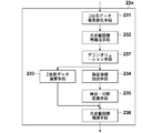
- FIG. 11 shows the image generation means 23 in this embodiment.
- the image generation unit 23 includes a two-wavelength data complex number conversion unit 231, a photoacoustic image reconstruction unit 232, a two-wavelength data calculation unit 233, an intensity information extraction unit 234, a detection / logarithm conversion unit 235, and a photoacoustic image construction unit 236.
- the two-wavelength data complex numbering means 231 generates complex number data in which one of the first photoacoustic signal and the second photoacoustic signal is a real part and the other is an imaginary part. In the following description, it is assumed that the two-wavelength data complexization unit 231 generates complex data having the first photoacoustic signal as a real part and the second photoacoustic signal as an imaginary part.
- the photoacoustic image reconstruction means 232 receives complex number data from the two-wavelength data complex numbering means 231 and reconstructs the photoacoustic signal.
- the photoacoustic image reconstruction means 232 performs image reconstruction from the input complex number data by a Fourier transform method (FTA method).
- FFA method Fourier transform method
- For the image reconstruction by the Fourier transform method for example, a conventionally known method described in the document “Photoacoustic Image Reconstruction-A A Quantitative Analysis” Jonathan I Isperl I et al. SPIE-OSA Vol. it can.
- the photoacoustic image reconstruction unit 232 inputs Fourier transform data indicating the reconstructed image to the intensity information extraction unit 234 and the two-wavelength data calculation unit 233.
- the two-wavelength data calculation means 233 extracts the relative magnitude of the relative signal intensity between the photoacoustic data corresponding to each wavelength.
- the two-wavelength data calculation unit 233 uses the reconstructed image reconstructed by the photoacoustic image reconstruction unit 232 as input data, and compares the real part and the imaginary part from the input data that is complex data.
- the intensity information extraction unit 234 generates intensity information indicating the signal intensity based on the photoacoustic data corresponding to each wavelength.
- the intensity information extraction unit 234 uses the reconstructed image reconstructed by the photoacoustic image reconstruction unit 232 as input data, and generates intensity information from the input data that is complex number data. For example, when the complex number data is represented by X + iY, the intensity information extraction unit 234 extracts (X2 + Y2) 1/2 as the intensity information.
- the detection / logarithm conversion means 235 generates an envelope of data indicating the intensity information extracted by the intensity information extraction means 234, and then logarithmically converts the envelope to widen the dynamic range.
- the photoacoustic image construction means 236 receives the phase information from the two-wavelength data calculation means 233 and the intensity information after the detection / logarithmic conversion processing from the detection / logarithmic conversion means 235.
- the photoacoustic image construction unit 236 generates a photoacoustic image based on the input phase information and intensity information. For example, the photoacoustic image construction unit 236 determines the luminance (gradation value) of each pixel in the distribution image of the light absorber based on the input intensity information.
- the photoacoustic image construction unit 236 determines the color (display color) of each pixel in the light absorber distribution image based on, for example, phase information.
- the photoacoustic image construction unit 236 determines the color of each pixel based on the input phase information using, for example, a color map in which a phase range of 0 ° to 90 ° is associated with a predetermined color.
- the range of the phase from 0 ° to 45 ° is a range in which the first photoacoustic signal is larger than the second photoacoustic signal
- the source of the photoacoustic signal is more than the absorption with respect to light having a wavelength of 798 nm. It is considered that this is a vein through which blood mainly containing deoxygenated hemoglobin is less absorbed with respect to light having a wavelength of 756 nm.
- the first 45 ° to 90 ° phase is a range in which the first photoacoustic data is smaller than the second photoacoustic data, the source of the photoacoustic signal has a wavelength larger than the absorption with respect to light having a wavelength of 798 nm. It is considered that this is an artery through which blood mainly containing oxygenated hemoglobin flows, which absorbs more light at 756 nm.
- the phase gradually changes so that the phase is 0 ° in blue and the phase becomes colorless (white) as the phase approaches 45 °, and the phase 90 ° is red and the phase is 45.
- the portion corresponding to the artery can be represented in red
- the portion corresponding to the vein can be represented in blue.
- the gradation value may be constant and only the color classification of the portion corresponding to the artery and the portion corresponding to the vein may be performed according to the phase information.
- Generation of the photoacoustic image based on the photoacoustic signals corresponding to the light of the two wavelengths described above is performed by light irradiation from the light irradiation unit 32 (FIG. 2A) of the probe 11 and the light emission unit 16 (FIG. 1) of the puncture needle 15.
- the light of the first wavelength and the light of the second wavelength are sequentially emitted from the light emitting unit 16 of the puncture needle 15 punctured in the subject, and a photoacoustic signal corresponding to each wavelength is detected to detect photoacoustics.
- An image (second photoacoustic image) is generated.
- combines a 1st photoacoustic image and a 2nd photoacoustic image may be the same as that of 1st Embodiment.
- the light of the first wavelength and the light of the second wavelength are irradiated from the light irradiation from the light irradiation unit 32 of the probe 11 and the light irradiation from the light emitting unit 16 of the puncture needle 15, respectively.
- light having a single wavelength may be emitted from the light emitting portion 16 of the puncture needle 15.
- the complexization by the two-wavelength data complexing means 231 and the extraction of phase information by the two-wavelength data calculating means 233 are not necessary.
- a photoacoustic image may be generated based on the intensity information extracted by the intensity information extraction unit 234.
- the laser unit 13 irradiates the subject with laser beams having a plurality of different wavelengths.
- a photoacoustic signal photoacoustic data
- by irradiating light with a wavelength that makes it possible to distinguish between an artery and a vein it is possible to determine whether the blood vessel existing in the direction in which the puncture needle travels is an artery or a vein. You can do it more safely.
- complex number data in which one of the first photoacoustic signal and the second photoacoustic signal obtained at two wavelengths is a real part and the other is an imaginary part is generated.
- Two reconstructed images are generated from the complex number data by Fourier transform.
- FIG. 11 shows image generation means 23a in the third embodiment of the present invention.
- the image generation unit 23a includes a deconvolution unit 237 in addition to the configuration of the image generation unit 23 in the second embodiment shown in FIG.
- the deconvolution means 237 generates a signal obtained by deconvolution of the photodifferential waveform, which is a differential waveform of the time waveform of the light intensity of the light applied to the subject, from the photoacoustic signal reconstructed by the photoacoustic image reconstruction means 232. Generate.
- the deconvolution means 237 executes a process of deconvolution of the optical differential waveform with respect to each of the real part and the imaginary part in the complexized data.
- the two-wavelength data calculation means 233 generates phase information from the photoacoustic signal obtained by deconvolution of the optical differential waveform.
- the intensity information extraction means 234 extracts intensity information from the photoacoustic signal from which the optical differential waveform is deconvoluted.
- the subsequent processing is the same as in the second embodiment. Note that irradiation with a plurality of wavelengths of light is not essential for deconvolution. That is, it is good also as irradiating a test object with the light of a single wavelength, and deconvolving an optical differential waveform from the detected photoacoustic signal.
- the deconvolution means 237 converts the reconstructed photoacoustic signal from a time domain signal to a frequency domain signal, for example, by discrete Fourier transform. Further, the optical differential waveform is also converted from a time domain signal to a frequency domain signal by discrete Fourier transform.
- the deconvolution means 237 obtains the inverse of the Fourier-transformed optical differential waveform as an inverse filter, and applies the inverse filter to the Fourier-transformed frequency domain photoacoustic signal. By applying the inverse filter, the optical differential waveform is deconvoluted in the frequency domain signal. Thereafter, the photoacoustic signal to which the inverse filter is applied is converted from a frequency domain signal to a time domain signal by inverse Fourier transform.
- the pressure waveform pmicro (R, t) when the photoacoustic pressure wave generated from the micro-absorbing particle at the position r is observed at the position R with time t is [Phys. Rev. Lett. 86 (2001) From 3550.], the following spherical wave is obtained.
- I (t) is a time waveform of the light intensity of the excitation light
- the coefficient k is a conversion coefficient when the particle absorbs light and outputs an acoustic wave
- vs is the sound velocity of the subject.
- Positions r and R are vectors indicating positions in space.
- the pressure generated from the microabsorbent particles is a spherical wave proportional to the optical pulse differential waveform, as shown in the above formula.
- the pressure waveform actually obtained from the object to be imaged has a macroscopic absorber size, it is considered to be a waveform obtained by superimposing the above micro absorption waveforms (superposition principle).
- the absorption distribution of particles emitting macroscopic photoacoustic waves is A (r ⁇ R)
- the observation waveform of pressure from the macroscopic absorber is pmacro (R, t).
- the observation waveform pmacro (R, t) is expressed by the following pressure waveform equation: Indicated by As can be seen from the above equation (1), the observed waveform shows a convolution type of optical pulse differentiation.
- the absorber distribution can be obtained by deconvolution of the optical pulse differential waveform from the observed waveform.
- the example of deconvolution of the photodifferential waveform from the photoacoustic signal after reconstruction is described, but instead, the photodifferential waveform is deconvoluted from the photoacoustic signal before reconstruction. Also good.
- the differential waveform of the light irradiated to the subject is deconvoluted from the detected photoacoustic signal.
- the distribution of the light absorber can be obtained, and an absorption distribution image can be generated.
- an absorption distribution image blood vessels can be observed more clearly.
- Other effects are the same as those of the second embodiment.
- the laser light irradiation from the light irradiation unit 32 and the laser light irradiation from the light emitting unit 16 of the puncture needle 15 have been described as being performed separately, but the laser light irradiation from the light irradiation unit 32 and The laser light irradiation from the light emitting unit 16 of the puncture needle 15 may be performed simultaneously.
- the probe 11 simultaneously receives a photoacoustic signal caused by the laser light emitted from the light emitting unit 32 and a photoacoustic signal caused by the laser light emitted from the light emitting unit 16 of the puncture needle 15 (at a time). )To detect.
- the image display can be performed in a shorter time than when two photoacoustic images are generated and synthesized (superimposed) later.
- the example in which the first photoacoustic signal and the second photoacoustic signal are complexized has been described.
- the first photoacoustic signal and the second photoacoustic are not complexized.
- the signal may be reconstructed separately.
- the reconstruction method is not limited to the Fourier transform method.
- the ratio between the first photoacoustic signal and the second photoacoustic signal is calculated using the complex information after being converted into a complex number, but the ratio is calculated from the intensity information of both. The same effect can be obtained.
- the intensity information can be generated based on the signal intensity in the reconstructed image corresponding to one wavelength and the signal intensity in the reconstructed image corresponding to the other wavelength.
- the number of wavelengths of the pulsed laser light applied to the subject is not limited to two, and the subject is irradiated with three or more pulsed laser lights, and photoacoustic data corresponding to each wavelength is generated.
- a photoacoustic image may be generated based on this.
- the two-wavelength data calculation unit 233 may generate a relative signal intensity magnitude relationship between the photoacoustic data corresponding to each wavelength as the phase information.
- the intensity information extraction unit 234 may generate, as intensity information, a collection of signal intensities in photoacoustic data corresponding to each wavelength, for example.
- the photoacoustic image generation apparatus of this invention is not limited only to the said embodiment, Various correction and change are possible from the structure of the said embodiment. Those subjected to are also included in the scope of the present invention.
Landscapes
- Health & Medical Sciences (AREA)
- Life Sciences & Earth Sciences (AREA)
- Engineering & Computer Science (AREA)
- Heart & Thoracic Surgery (AREA)
- Molecular Biology (AREA)
- Biophysics (AREA)
- Pathology (AREA)
- Biomedical Technology (AREA)
- Human Computer Interaction (AREA)
- Medical Informatics (AREA)
- Physics & Mathematics (AREA)
- Surgery (AREA)
- Animal Behavior & Ethology (AREA)
- General Health & Medical Sciences (AREA)
- Public Health (AREA)
- Veterinary Medicine (AREA)
- Ultra Sonic Daignosis Equipment (AREA)
Abstract
Le problème de l'invention résidait en la fourniture d'un dispositif de génération d'images photo-acoustiques grâce auquel la localisation d'une aiguille de ponction pouvait être assurée par imagerie photo-acoustique. Le problème est résolu par un laser (13) émettant un faisceau laser. Le faisceau laser est irradié à partir d'un moyen d'irradiation de lumière vers un sujet. Une aiguille de ponction (15) présente une unité (16) émettrice de lumière et une irradiation par un faisceau laser est mise en œuvre via l'unité (16) émettrice de lumière. Une sonde (11) détecte le signal photo-acoustique généré lorsqu'une matière absorbant la lumière à l'intérieur du sujet absorbe le faisceau laser irradié par le moyen d'irradiation de lumière. Une sonde (11) détecte également le signal photo-acoustique généré lorsqu'une matière absorbant la lumière à l'intérieur du sujet absorbe un faisceau laser émis par l'unité (16) émettrice de lumière. Un moyen (23) de génération d'images génère une image photo-acoustique sur base des signaux photo-acoustiques.
Applications Claiming Priority (4)
| Application Number | Priority Date | Filing Date | Title |
|---|---|---|---|
| JP2011127049 | 2011-06-07 | ||
| JP2011-127049 | 2011-06-07 | ||
| JP2012-122751 | 2012-05-30 | ||
| JP2012122751A JP5743957B2 (ja) | 2011-06-07 | 2012-05-30 | 光音響画像生成装置及び方法 |
Publications (1)
| Publication Number | Publication Date |
|---|---|
| WO2012169178A1 true WO2012169178A1 (fr) | 2012-12-13 |
Family
ID=47295763
Family Applications (1)
| Application Number | Title | Priority Date | Filing Date |
|---|---|---|---|
| PCT/JP2012/003686 Ceased WO2012169178A1 (fr) | 2011-06-07 | 2012-06-06 | Dispositif et procédé de génération d'images photo-acoustiques |
Country Status (2)
| Country | Link |
|---|---|
| JP (1) | JP5743957B2 (fr) |
| WO (1) | WO2012169178A1 (fr) |
Cited By (6)
| Publication number | Priority date | Publication date | Assignee | Title |
|---|---|---|---|---|
| WO2015015932A1 (fr) * | 2013-08-02 | 2015-02-05 | 富士フイルム株式会社 | Appareil de génération d'image photoacoustique et procédé de commande de source de lumière |
| WO2015111280A1 (fr) * | 2014-01-27 | 2015-07-30 | 富士フイルム株式会社 | Dispositif de traitement de signaux photoacoustiques, système de traitement de signaux photoacoustiques et procédé de traitement de signaux photoacoustiques |
| CN104902823A (zh) * | 2013-01-09 | 2015-09-09 | 富士胶片株式会社 | 光声图像生成装置及插入物 |
| WO2016158095A1 (fr) * | 2015-03-30 | 2016-10-06 | 富士フイルム株式会社 | Aiguille de biopsie et dispositif de mesure photoacoustique |
| WO2017002337A1 (fr) * | 2015-06-30 | 2017-01-05 | 富士フイルム株式会社 | Appareil de génération d'images photoacoustiques et élément d'insertion |
| WO2022202282A1 (fr) * | 2021-03-25 | 2022-09-29 | テルモ株式会社 | Dispositif d'administration |
Families Citing this family (13)
| Publication number | Priority date | Publication date | Assignee | Title |
|---|---|---|---|---|
| JP5952327B2 (ja) * | 2013-03-22 | 2016-07-13 | 富士フイルム株式会社 | 光音響計測装置及び穿刺針 |
| KR102149322B1 (ko) * | 2013-05-20 | 2020-08-28 | 삼성메디슨 주식회사 | 광음향 프로브 어셈블리 및 이를 포함하는 광음향 영상 장치 |
| WO2016002167A1 (fr) | 2014-06-30 | 2016-01-07 | 富士フイルム株式会社 | Câble à fibre optique et son procédé de fabrication, et module source de lumière qui en est équipé |
| JP6371847B2 (ja) * | 2014-06-30 | 2018-08-08 | 富士フイルム株式会社 | 光音響画像生成装置、信号処理装置、及び光音響画像生成方法 |
| WO2016042716A1 (fr) | 2014-09-19 | 2016-03-24 | 富士フイルム株式会社 | Procédé et dispositif de génération d'image photo-acoustique |
| JP6374012B2 (ja) | 2014-09-25 | 2018-08-15 | 富士フイルム株式会社 | 光音響画像生成装置 |
| WO2016051764A1 (fr) * | 2014-09-29 | 2016-04-07 | 富士フイルム株式会社 | Dispositif de génération d'image photo-acoustique |
| WO2016051738A1 (fr) | 2014-09-29 | 2016-04-07 | 富士フイルム株式会社 | Dispositif d'imagerie photoacoustique |
| JP6411655B2 (ja) | 2015-06-30 | 2018-10-24 | 富士フイルム株式会社 | 光音響画像生成装置及び挿入物 |
| JP6411664B2 (ja) | 2015-08-31 | 2018-10-24 | 富士フイルム株式会社 | 光音響画像生成装置及び挿入物 |
| EP3345551B1 (fr) * | 2015-08-31 | 2020-02-26 | FUJIFILM Corporation | Dispositif de génération d'images photo-acoustiques et objet d'insertion |
| JP6454031B2 (ja) * | 2015-11-24 | 2019-01-16 | 富士フイルム株式会社 | 光ファイバ挿入長調整機構、挿入物、及びアタッチメント部材 |
| EP3409211B1 (fr) | 2016-01-25 | 2019-12-11 | Fujifilm Corporation | Implant et élément de fixation |
Citations (3)
| Publication number | Priority date | Publication date | Assignee | Title |
|---|---|---|---|---|
| JPS5740632A (en) * | 1980-08-26 | 1982-03-06 | Olympus Optical Co Ltd | Probe for photo-acoustic spectroscopic inspection |
| JPH0492647A (ja) * | 1990-08-09 | 1992-03-25 | Yokogawa Medical Syst Ltd | 超音波診断装置 |
| WO2010009747A1 (fr) * | 2008-07-25 | 2010-01-28 | Helmholtz Zentrum München Deutsches Forschungszentrum Für Gesundheit Und Umwelt (Gmbh) | Tomographie opto-acoustique multi-spectrale quantitative (msot) de biomarqueurs tissulaires |
Family Cites Families (1)
| Publication number | Priority date | Publication date | Assignee | Title |
|---|---|---|---|---|
| JPH0754855Y2 (ja) * | 1989-06-16 | 1995-12-18 | アロカ株式会社 | 光音響センサ |
-
2012
- 2012-05-30 JP JP2012122751A patent/JP5743957B2/ja not_active Expired - Fee Related
- 2012-06-06 WO PCT/JP2012/003686 patent/WO2012169178A1/fr not_active Ceased
Patent Citations (3)
| Publication number | Priority date | Publication date | Assignee | Title |
|---|---|---|---|---|
| JPS5740632A (en) * | 1980-08-26 | 1982-03-06 | Olympus Optical Co Ltd | Probe for photo-acoustic spectroscopic inspection |
| JPH0492647A (ja) * | 1990-08-09 | 1992-03-25 | Yokogawa Medical Syst Ltd | 超音波診断装置 |
| WO2010009747A1 (fr) * | 2008-07-25 | 2010-01-28 | Helmholtz Zentrum München Deutsches Forschungszentrum Für Gesundheit Und Umwelt (Gmbh) | Tomographie opto-acoustique multi-spectrale quantitative (msot) de biomarqueurs tissulaires |
Cited By (17)
| Publication number | Priority date | Publication date | Assignee | Title |
|---|---|---|---|---|
| EP3329856A1 (fr) * | 2013-01-09 | 2018-06-06 | FUJIFILM Corporation | Dispositif de génération d'images photoacoustiques et objet d'insertion |
| CN107252304A (zh) * | 2013-01-09 | 2017-10-17 | 富士胶片株式会社 | 光声图像生成装置及插入物 |
| US11510575B2 (en) | 2013-01-09 | 2022-11-29 | Fujifilm Corporation | Photoacoustic image generating device and insertion object |
| EP2944264A4 (fr) * | 2013-01-09 | 2016-01-06 | Fujifilm Corp | Dispositif de formation d'image photoacoustique, et insertion |
| CN104902823A (zh) * | 2013-01-09 | 2015-09-09 | 富士胶片株式会社 | 光声图像生成装置及插入物 |
| CN105451661A (zh) * | 2013-08-02 | 2016-03-30 | 富士胶片株式会社 | 光声图像生成装置及光源控制方法 |
| JP2015043969A (ja) * | 2013-08-02 | 2015-03-12 | 富士フイルム株式会社 | 光音響画像生成装置及び光源制御方法 |
| WO2015015932A1 (fr) * | 2013-08-02 | 2015-02-05 | 富士フイルム株式会社 | Appareil de génération d'image photoacoustique et procédé de commande de source de lumière |
| JP2015139465A (ja) * | 2014-01-27 | 2015-08-03 | 富士フイルム株式会社 | 光音響信号処理装置、システム、及び方法 |
| WO2015111280A1 (fr) * | 2014-01-27 | 2015-07-30 | 富士フイルム株式会社 | Dispositif de traitement de signaux photoacoustiques, système de traitement de signaux photoacoustiques et procédé de traitement de signaux photoacoustiques |
| WO2016158095A1 (fr) * | 2015-03-30 | 2016-10-06 | 富士フイルム株式会社 | Aiguille de biopsie et dispositif de mesure photoacoustique |
| JPWO2016158095A1 (ja) * | 2015-03-30 | 2018-01-11 | 富士フイルム株式会社 | 生検針および光音響計測装置 |
| US10499887B2 (en) | 2015-03-30 | 2019-12-10 | Fujifilm Corporation | Biopsy needle and photoacoustic measurement apparatus |
| JPWO2017002337A1 (ja) * | 2015-06-30 | 2018-01-11 | 富士フイルム株式会社 | 光音響画像生成装置及び挿入物 |
| WO2017002337A1 (fr) * | 2015-06-30 | 2017-01-05 | 富士フイルム株式会社 | Appareil de génération d'images photoacoustiques et élément d'insertion |
| US10765324B2 (en) | 2015-06-30 | 2020-09-08 | Fujifilm Corporation | Photoacoustic image generation apparatus and insert |
| WO2022202282A1 (fr) * | 2021-03-25 | 2022-09-29 | テルモ株式会社 | Dispositif d'administration |
Also Published As
| Publication number | Publication date |
|---|---|
| JP2013013713A (ja) | 2013-01-24 |
| JP5743957B2 (ja) | 2015-07-01 |
Similar Documents
| Publication | Publication Date | Title |
|---|---|---|
| JP5743957B2 (ja) | 光音響画像生成装置及び方法 | |
| JP5340648B2 (ja) | 被検体情報算出装置及び被検体情報算出方法 | |
| JP5349839B2 (ja) | 生体情報イメージング装置 | |
| JP5709399B2 (ja) | 被検体情報取得装置およびその制御方法、ならびにプログラム | |
| CN103260502B (zh) | 被检体信息获取设备和被检体信息获取方法 | |
| US9888856B2 (en) | Photoacoustic image generation apparatus, system and method | |
| US20090054763A1 (en) | System and method for spectroscopic photoacoustic tomography | |
| EP2016891B1 (fr) | Appareil médical pour obtenir des informations indiquant l'état interne d'un objet basé sur une interaction physique entre des ondes à ultrasons et la lumière | |
| US9360551B2 (en) | Object information acquiring apparatus and control method thereof | |
| US20120302866A1 (en) | Photoacoustic imaging apparatus and photoacoustic imaging method | |
| JP5911196B2 (ja) | 光音響イメージング装置 | |
| JP5777394B2 (ja) | 光音響画像化方法および装置 | |
| WO2013128846A1 (fr) | Dispositif et procédé de génération d'images photoacoustiques | |
| JP6000778B2 (ja) | 被検体情報取得装置および被検体情報取得装置の制御方法 | |
| JP2015503392A (ja) | Usイメージングにおけるpa効果を使用したニードル・ナビゲーションのためのシステム及び方法 | |
| JP2013158531A (ja) | 被検体情報取得装置及び被検体情報取得方法 | |
| US20180228377A1 (en) | Object information acquiring apparatus and display method | |
| JP2012239784A (ja) | 光音響撮像装置およびその作動方法 | |
| JP2023123874A (ja) | 光音響イメージングシステム、光音響イメージングシステムの制御方法、および、プログラム | |
| JP6066230B2 (ja) | 光音響画像生成装置およびその作動方法 | |
| JP6664176B2 (ja) | 光音響装置、情報処理方法、およびプログラム | |
| CN102307528B (zh) | 生物体观测装置以及生物体断层图像生成方法 | |
| JP2017047056A (ja) | 被検体情報取得装置 | |
| JP5946230B2 (ja) | 光音響画像化方法および装置 | |
| US20200060551A1 (en) | System, image processing apparatus, measurement control method, and image processing method |
Legal Events
| Date | Code | Title | Description |
|---|---|---|---|
| 121 | Ep: the epo has been informed by wipo that ep was designated in this application |
Ref document number: 12797244 Country of ref document: EP Kind code of ref document: A1 |
|
| NENP | Non-entry into the national phase |
Ref country code: DE |
|
| 122 | Ep: pct application non-entry in european phase |
Ref document number: 12797244 Country of ref document: EP Kind code of ref document: A1 |