WO2012169253A1 - Dispositif de fabrication d'écran, et procédé de fabrication d'écran - Google Patents
Dispositif de fabrication d'écran, et procédé de fabrication d'écran Download PDFInfo
- Publication number
- WO2012169253A1 WO2012169253A1 PCT/JP2012/056665 JP2012056665W WO2012169253A1 WO 2012169253 A1 WO2012169253 A1 WO 2012169253A1 JP 2012056665 W JP2012056665 W JP 2012056665W WO 2012169253 A1 WO2012169253 A1 WO 2012169253A1
- Authority
- WO
- WIPO (PCT)
- Prior art keywords
- screen
- substrate
- partition wall
- manufacturing apparatus
- solvent
- Prior art date
- Legal status (The legal status is an assumption and is not a legal conclusion. Google has not performed a legal analysis and makes no representation as to the accuracy of the status listed.)
- Ceased
Links
Images



Classifications
-
- G—PHYSICS
- G03—PHOTOGRAPHY; CINEMATOGRAPHY; ANALOGOUS TECHNIQUES USING WAVES OTHER THAN OPTICAL WAVES; ELECTROGRAPHY; HOLOGRAPHY
- G03B—APPARATUS OR ARRANGEMENTS FOR TAKING PHOTOGRAPHS OR FOR PROJECTING OR VIEWING THEM; APPARATUS OR ARRANGEMENTS EMPLOYING ANALOGOUS TECHNIQUES USING WAVES OTHER THAN OPTICAL WAVES; ACCESSORIES THEREFOR
- G03B21/00—Projectors or projection-type viewers; Accessories therefor
- G03B21/54—Accessories
- G03B21/56—Projection screens
-
- G—PHYSICS
- G03—PHOTOGRAPHY; CINEMATOGRAPHY; ANALOGOUS TECHNIQUES USING WAVES OTHER THAN OPTICAL WAVES; ELECTROGRAPHY; HOLOGRAPHY
- G03B—APPARATUS OR ARRANGEMENTS FOR TAKING PHOTOGRAPHS OR FOR PROJECTING OR VIEWING THEM; APPARATUS OR ARRANGEMENTS EMPLOYING ANALOGOUS TECHNIQUES USING WAVES OTHER THAN OPTICAL WAVES; ACCESSORIES THEREFOR
- G03B21/00—Projectors or projection-type viewers; Accessories therefor
- G03B21/54—Accessories
- G03B21/56—Projection screens
- G03B21/567—Projection screens for colour projection
Definitions
- the present invention relates to a screen manufacturing apparatus and a screen manufacturing method for manufacturing a screen used in an image display device, and more particularly to a screen manufacturing apparatus and a screen manufacturing method for manufacturing a fluorescent screen on which a phosphor layer is formed.
- Some image display devices such as projectors irradiate light on a fluorescent screen and display an image using fluorescence generated on the fluorescent screen.
- a general phosphor screen is divided into a plurality of color regions by partition walls, and a phosphor layer that absorbs incident light and generates fluorescence is formed in each color region.
- the phosphor layer is formed by applying a curable phosphor material to each color region separated by a partition and curing the phosphor material. For this reason, a certain amount of thickness is required for the barrier ribs so that the phosphor material applied to each color area is not cured before entering the other color area.
- a photosensitive material is applied to a substrate of a screen, and the photosensitive material is irradiated with light through a photomask on which a partition pattern is drawn.
- a photolithography method is known.
- the formation of partition walls using a photolithography method has a problem in productivity because of expensive equipment and many manufacturing processes.
- Patent Documents 1 and 2 describe a technique capable of forming a partition without using a photolithography method.
- a pattern is formed by scraping the color region portion of the paste layer containing the spherical inorganic powder using a sandblasting method. The pattern is baked to form partition walls.
- An object of the present invention is to provide a screen manufacturing apparatus and a screen manufacturing method capable of easily manufacturing a partition wall of a flexible screen substrate.
- the screen manufacturing apparatus includes an application mechanism that applies partition wall solvent to the substrate of the screen, and an adjustment mechanism that adjusts the orientation of the substrate so that the application surface of the substrate on which the partition solvent is applied faces downward. And a curing mechanism that cures the partition wall solvent applied to the downwardly-applied application surface.
- the screen manufacturing method includes a step of applying a partition wall solvent to the substrate of the screen, and a step of adjusting the orientation of the substrate so that an application surface of the substrate on which the partition wall solvent is applied faces downward. And a step of curing the partition wall solvent applied to the downwardly-applied application surface.
- a screen manufacturing apparatus that manufactures a fluorescent screen used in an image display apparatus such as a projector by a roll-to-sheet method will be described. Further, in the present embodiment, a rear projector that irradiates light from the back to the screen and displays an image using fluorescence generated by the fluorescent screen is assumed as the image display device, and the fluorescent screen is used for the rear projector. It is said to be a screen.
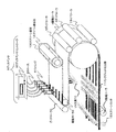
- FIG. 1 is a perspective view showing a screen manufacturing apparatus of the present embodiment
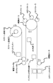
- FIG. 2 is a schematic view schematically showing the screen manufacturing apparatus of the present embodiment.
- the screen manufacturing apparatus includes a screen substrate core 1, driving rollers 2, 4 and 8, guide rollers 3, 5 to 7, a dispenser 9, a UV (ultraviolet) light source 10, and an ink jet type.
- a discharger 11 and a screen cutter 12 are provided.
- the screen substrate core 1 is a winding core for winding the screen substrate 100, which is a fluorescent screen substrate, in a roll shape.
- the screen substrate 100 has such flexibility that it is not damaged even when it is wound in a roll shape.
- the screen substrate 100 is formed of a fluorescent transmission member that transmits fluorescent light generated by the fluorescent screen.
- the driving rollers 2, 4 and 8 and the guide rollers 3, 5 to 7 constitute an adjustment mechanism that conveys the screen substrate 100 while adjusting the orientation of the screen substrate 100.
- the drive rollers 2, 4, and 8 are in contact with the screen substrate 100 unwound from the screen substrate core 1, and are rotated by a drive motor (not shown) to convey the screen substrate 100 wound around the screen substrate core 1. . Further, the guide rollers 3 and 5 to 7 are rotated and driven by a frictional force with the screen substrate 100 while being in contact with the screen substrate 100 to adjust the orientation of the screen substrate 100.
- the driving roller 2 conveys the screen substrate 100 wound around the screen substrate core 1 in a predetermined direction in the horizontal direction (or substantially horizontal direction) while unwinding the screen substrate 100.
- the predetermined direction is leftward.
- the guide roller 3 and the driving roller 4 invert the screen substrate 100 conveyed by the driving roller 2 upside down, and the screen substrate 100 that has been inverted upside down has a first direction in the horizontal direction (or substantially horizontal direction). Transport rightward, opposite to
- the guide roller 3 is provided on the left side of the driving roller 2 in contact with the driving roller 2, or is separated from the driving roller 2 and the screen substrate 100 by a thickness or less, and is conveyed leftward by the driving roller 2.
- the transport direction is changed to the vertical direction.
- the guide roller 3 is described as changing the conveyance direction of the screen substrate 100 downward in the vertical direction.
- the driving roller 4 is driven to rotate in the direction opposite to that of the driving roller 2 and conveys the screen substrate 100 whose conveyance direction is changed downward by the guide roller 3 to the right. Thereby, the screen substrate 100 conveyed by the driving roller 2 is turned upside down.
- the guide rollers 5 to 7 are provided in contact with the driving roller 4 or separated from the driving roller 4 by a thickness less than or equal to the thickness of the screen substrate 100, and the conveyance direction of the screen substrate 100 conveyed by the driving roller 4 is leftward. change. Thereby, the upper and lower sides of the screen substrate 100 are inverted again and returned to the original.
- the driving roller 8 is driven to rotate in the direction opposite to that of the driving roller 4, and the screen substrate 100 whose conveyance direction is changed to the left by the guide rollers 5 to 7 is conveyed to the left as it is.
- the dispenser 9 cures the partition wall solvent, which becomes a partition wall that separates the phosphor layers of the phosphor screen by being cured, with respect to the screen substrate 100 so that the screen substrate 100 is partitioned into a plurality of color regions by the partition wall solvent. It is an application mechanism that discharges from the upper surface of the screen substrate 100.
- the partition wall solvent has an adhesive property that does not sag even when the coated surface applied to the screen substrate 100 is faced down, and a curability that is cured by light or heat such as ultraviolet rays or infrared rays.
- the partition wall solvent is assumed to have ultraviolet curability that cures by ultraviolet rays.
- the partition of the fluorescent screen usually absorbs or reflects light incident on the fluorescent screen so as not to be seen by the viewer of the rear projector, thereby improving the contrast of the display image displayed by the rear projector. Also functions as a black stripe. For this reason, it is desirable that the partition wall solvent has a light absorbing property or a light reflecting property.
- the dispenser 9 includes a plurality of syringes 91, a dispenser controller 92, and a hose 93.
- Each syringe 91 is a container for containing a partition wall solvent, and has a needle (not shown) for discharging the partition wall solvent at the lower end.
- Each syringe 91 is attached so as to be positioned above the screen substrate 100 conveyed leftward by the drive roller 2. Further, a plurality of syringes 91 are attached so as to be periodically arranged in a direction orthogonal to the direction of conveyance of the screen substrate 100 by the drive roller 2.
- the dispenser controller 92 injects the partition wall solvent into each syringe 91 via the hose 93 and pushes the partition wall solvent in each syringe 91 to discharge from the needle to apply the partition wall solvent to the screen substrate 100.
- the dispenser controller 92 continuously discharges a predetermined amount of partition wall solvent from each needle 92 so that the partition wall solvent on the upper surface of the screen substrate 100 is formed in a stripe shape in which the partition walls are periodically arranged. A solvent is applied to the screen substrate 100. In this case, the space between the stripes formed by the partition wall solvent is a color region.
- the UV light source 10 is a curing mechanism that forms partition walls by curing the partition wall solvent by irradiating the partition wall solvent applied to the screen substrate 100 with ultraviolet rays.
- the UV light source 10 is provided so as to be positioned below the screen substrate 100 being conveyed rightward by the driving roller 4, and the screen substrate 100 is turned upside down by the guide roller 3 and the driving roller 4. After a predetermined time has elapsed, the screen substrate 100 is attached to a position where ultraviolet rays are irradiated.
- the partition wall solvent 101 may be lowered.
- the screen substrate 100 is turned upside down so that the coating surface faces downward. It is possible to suppress dripping.
- the predetermined time is desirably a time from when the coating surface is turned downward until the height of the partition wall solvent reaches a threshold value that is sufficiently high as the partition wall 103. Note that the predetermined time varies depending on the degree of adhesion and the amount of the partition wall solvent.
- the ink jet type ejector 11 is mounted so as to be positioned above the screen substrate 100 conveyed rightward by the driving roller 8, and is incident on each color region separated by the partition of the screen substrate 100 by incident light that is cured.
- This is a phosphor coating mechanism that forms a phosphor layer in each color region by discharging a phosphor material that becomes a phosphor layer that generates fluorescence. Note that the phosphor material is naturally curable.
- the screen cutter 12 is a cutting mechanism that cuts the screen substrate 100 conveyed by the driving roller 8 into a predetermined size to form a fluorescent screen.
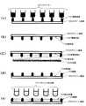
- FIG. 3 is a view for explaining a manufacturing process of the fluorescent screen in the screen manufacturing apparatus shown in FIGS. 1 and 2, and a cross-sectional view in which the screen substrate 100 is cut in a direction orthogonal to the transport direction is shown. .
- the screen substrate 100 wound around the screen substrate core 1 is conveyed leftward by the driving roller 2 at a constant speed. While the screen substrate 100 is being conveyed leftward, the dispenser 9 discharges the partition wall solvent from above onto the screen substrate 100 at a constant speed, as shown in FIG. A partition wall solvent is applied in a stripe pattern on the upper surface of the substrate.
- the screen substrate 100 coated with the partition wall solvent 101 is conveyed to the left end of the driving roller 2 by the driving roller 2.
- the screen substrate 100 is turned downward by the guide roller 3 and further conveyed rightward by the drive roller 4.
- the screen substrate 100 is turned upside down, and the orientation of the screen substrate 100 is adjusted so that the coating surface 102 coated with the partition wall solvent 101 faces downward, as shown in FIG.
- the screen substrate 100 is conveyed rightward with the application surface 102 facing downward by the driving roller 4. While the screen substrate 100 is conveyed rightward, the UV light source 10 irradiates the partition wall solvent 101 applied to the coating surface 102 with ultraviolet rays as shown in FIG. A partition wall 103 is formed by curing.
- the screen substrate 100 is conveyed by the driving roller 4 to above the driving roller 4, and thereafter conveyed by the guides of the guide rollers 5 to 7 to the lower part of the driving roller 4 while changing the conveying direction along the driving roller 4. Is done. Thereby, the upper and lower sides of the screen substrate 100 are inverted again, and the coating surface 102 faces upward as shown in FIG.
- the drive roller 4 is preferably provided with a groove at a location where the partition wall solvent is applied so that the drive roller 4 does not come into contact with the partition wall solvent applied to the screen substrate 100.
- the screen substrate 100 conveyed to the lower part of the driving roller 4 is conveyed leftward by the driving roller 8.
- the phosphor is applied to each color region divided by the partition wall 103 of the screen substrate 100 by the ink jet type ejector 11, and the phosphor layer 104 is formed in each color region.
- the ink jet ejector 11 applies the phosphor material to each color region so that the phosphor layers 104 having different fluorescence colors (wavelengths) are arranged in a predetermined order with the partition wall interposed therebetween.
- the screen substrate 100 is further conveyed leftward by the driving roller 8 and cut into a predetermined size by the screen cutter 12 to form a fluorescent screen.
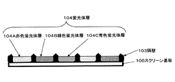
- FIG. 4 and 5 are diagrams showing the fluorescent screen manufactured by the manufacturing process as described above.
- 4 is a front view of the fluorescent screen
- FIG. 5 is a cross-sectional view of the fluorescent screen cut in a direction perpendicular to the longitudinal direction of the partition walls.
- the stripe-shaped partition walls 103 arranged periodically are formed on the screen substrate 100, and the phosphor layer 104 is formed in the color region that is the region between the partition walls 103.
- the phosphor layer 104 includes a red phosphor layer 104A that generates red fluorescence, a green phosphor layer 104B that generates green fluorescence, and a blue phosphor layer 104C that generates blue fluorescence.
- the body layer 104A, the green phosphor layer 104B, and the blue phosphor layer 104C are repeatedly arranged in this order with the partition wall 103 interposed therebetween.
- 6 and 7 are sectional views showing other examples of the fluorescent screen.
- a color filter layer 111 that selectively transmits light of a specific color
- a diffusion layer 112 that diffuses light
- a phosphor layer 113 that generates light are arranged in this order.
- Such a phosphor screen for example, ejects the material of each layer in order so that the inkjet ejector 11 is laminated in each color region in the order of the color filter layer 111, the diffusion layer 112, and the phosphor layer 113.
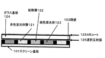
- the fluorescent screen shown in FIG. 7 receives blue light, emits red and green light to the front using fluorescence, and emits blue light to the front by diffusing the incident light. is there.
- this phosphor screen any one of the red phosphor layer 121, the diffusion layer 122, and the green phosphor layer 123 is repeatedly arranged in this order with the partition walls in each color region of the screen substrate 100.
- a glass substrate 124 is formed so as to cover all of the partition wall 103, the red phosphor layer 121, the diffusion layer 122, and the green phosphor layer 123.
- a selective reflection film 126 that transmits incident light and transmits fluorescence is formed on the surface of the glass substrate 124 on the partition wall 103 side, and incident light is reflected on the surface opposite to the surface on which the selective reflection film is formed.
- An AR (Anti-Reflection) coat 127 to be suppressed is formed.
- the material of each layer is applied so that the inkjet discharger 11 is formed in the order of the red phosphor layer 121, the diffusion layer 122, and the green phosphor layer 123 with the partition wall 103 interposed therebetween. Thereafter, the glass substrate 124 is formed by being laminated. The glass substrate 124, the partition wall 103, the red phosphor layer 121, the diffusion layer 122, and the green phosphor layer 123 are bonded with, for example, an adhesive.
- the application surface coated with the partition wall solvent is directed downward, and then cured to form the partition wall, so that it is possible to reduce the dripping of the partition wall solvent, A sufficient height as a partition wall can be secured. For this reason, since it is not necessary to form a partition using a photolithographic method or a sandblasting method, it becomes possible to manufacture a screen at low cost. In addition, since it is not necessary to use an adhesive such as adhesive glass, a screen can be manufactured at a low cost even for a flexible screen such as a projector screen. Therefore, it is possible to easily manufacture flexible partition walls of the screen substrate.
- the fluorescent screen is manufactured by the roll-to-sheet method, the fluorescent screen can be continuously manufactured, and the fluorescent screen can be manufactured more easily.
- the partition wall solvent is cured and formed as a partition after a predetermined time after the screen substrate 100 is turned downward, so that a sufficient height as the partition can be ensured more reliably.
- FIG. 8 is a perspective view showing the screen manufacturing apparatus of the present embodiment
- FIG. 9 is a schematic view schematically showing the screen manufacturing apparatus of the present embodiment.
- the screen manufacturing apparatus includes drive rollers 2A, 4A, and 8A, guide rollers 3A, 5A to 7A, a dispenser 9A, a UV light source 10A, an ink jet dispenser 11A, and a conveyor belt 21. And a guide plate 22.
- the conveyance belt 21 sucks and holds the screen substrate 200 which is a fluorescent screen substrate.
- the screen substrate 200 is a sheet-like substrate formed in the size of a fluorescent screen.
- the screen substrate 200 is formed of a fluorescent transmission member having the same flexibility as the screen substrate 100 of the first embodiment.
- the driving rollers 2A, 4A, and 8A, the guide rollers 3A, 5A to 7A, and the guide plate 22 constitute an adjustment mechanism that conveys the screen substrate 200 while adjusting the orientation of the screen substrate 200.
- the drive rollers 2A, 4A, and 8A are in contact with the transport belt 21 and are rotationally driven by a drive motor (not shown) to drive the transport belt 21 so that the screen substrate 200 that is attracted and held by the transport belt 21 is removed.
- Transport Further, the guide rollers 3A, 5A to 7A are rotationally driven by a frictional force with the screen substrate 200 in a state where they are in contact with the screen substrate 200, thereby changing the conveyance direction of the screen substrate 200.
- the guide plate 22 is a curved plate-like member and regulates the conveyance direction of the screen substrate 200.
- the drive roller 2A is a first transport mechanism that drives the transport belt 21 to transport the screen substrate 200 in a predetermined direction in the horizontal direction (or substantially horizontal direction).
- the predetermined direction is leftward as in the first embodiment.
- the guide roller 3A, the drive roller 4A, and the guide plate 22 invert the screen substrate 200 conveyed by the drive roller 2A so that the screen substrate 200 that has been inverted upside down is horizontally (or substantially horizontal).
- a second transport mechanism that transports in the right direction opposite to the first direction.
- the guide roller 3A is provided on the left side of the driving roller 2A in contact with the conveying belt 21 or separated from the conveying belt 21 by a thickness equal to or less than the thickness of the screen substrate 200, and is conveyed leftward by the driving roller 2.
- the transport direction is changed to the vertical direction.
- the guide roller 3A will be described as changing the conveyance direction of the screen substrate 200 downward in the vertical direction.
- the guide plate 22 is a curved plate-like member, the inside of the curved portion faces the screen substrate 200 conveyed by the driving roller 2A, and the screen substrate 200 is conveyed and driven along the inside of the curved portion. It is provided so as to be inserted between the roller 2A and the guide roller 3A.
- the driving roller 4A is rotated in the opposite direction to the driving roller 2A and drives the conveying belt 21, thereby conveying the screen substrate 200 whose conveying direction is changed downward by the guide roller 3A to the right. As a result, the screen substrate 200 is turned upside down.
- the guide rollers 5A to 7A and the drive roller 8A are a third transport mechanism that further reverses the screen substrate 200 transported by the drive roller 4 upside down and transports the screen substrate whose top and bottom are further reversed to the left. .
- the guide rollers 5A to 7A are provided in contact with the transport belt 21 or separated from the transport belt 21 by a thickness equal to or less than the thickness of the screen substrate 200, and the transport direction of the screen substrate 200 transported by the driving roller 4A is leftward. change. Thereby, the upper and lower sides of the screen substrate 100 are inverted again and returned to the original.
- the drive roller 8A is rotationally driven in the opposite direction to the drive roller 4A, drives the transport belt 21, and transports the screen substrate 200 whose transport direction is changed to the left by the guide rollers 5A to 7A as it is leftward.
- the dispenser 9A is an application mechanism having the same configuration as the dispenser 9 described in the first embodiment, and the partition wall solvent is applied to the screen substrate 200 so that the screen substrate 100 is partitioned into a plurality of color regions by the partition wall solvent. It is discharged from above and applied to the upper surface of the screen substrate 200.
- the partition wall solvent is the same solvent as in the first embodiment.
- the UV light source 10A is a curing mechanism that forms a partition wall by curing the partition wall solvent by irradiating the partition wall solvent applied to the screen substrate 200 with ultraviolet rays.
- the UV light source 10A is provided so as to be positioned below the screen substrate 200 conveyed rightward by the drive roller 4A, and the screen roller 200 is guided by the guide roller 3A, the drive roller 4A, and the guide plate 22.
- the screen substrate 200 is attached so as to be irradiated with ultraviolet rays after a predetermined time since the top and bottom are reversed.
- the ink jet type ejector 11A is mounted so as to be positioned above the screen substrate 200 conveyed by the driving roller 8A, and ejects phosphors to the respective color regions separated by the partition walls of the screen substrate 200, and the respective colors.
- a phosphor layer is formed in the region.
- the partition surface of the screen substrate having flexibility is easily manufactured because the coating surface coated with the partition wall solvent is directed downward and then cured to form the partition wall. It becomes possible.
- the adjustment mechanism of the screen manufacturing apparatus may be such that a sheet is fixed to the tray and the application surface is turned downward by turning the tray upside down.
- the partition wall solvent is applied in a stripe shape, it may be applied in a shape that divides the screen substrate into a plurality of color regions.
- the partition wall solvent may be applied in a matrix form.
- the screen manufactured by the screen manufacturing apparatus is not limited to the fluorescent screen, and is not particularly limited as long as it is a screen having partition walls.
Landscapes
- Physics & Mathematics (AREA)
- General Physics & Mathematics (AREA)
- Overhead Projectors And Projection Screens (AREA)
Abstract
La présente invention concerne un dispositif de fabrication d'écran, permettant de fabriquer facilement des cloisons de séparation pour un substrat d'écran souple. Un mécanisme d'application (9) applique un solvant de cloison de séparation sur le substrat pour un écran. Des mécanismes de réglage (2 à 8) règlent l'orientation du substrat de façon à ce que la surface d'application du substrat d'écran (100) sur laquelle est appliqué le solvant de cloison de séparation se trouve face vers le bas. Un mécanisme de traitement thermique (10) traite le solvant de cloison de séparation qui est appliqué sur la surface d'application qui se trouve face vers le bas.
Applications Claiming Priority (2)
| Application Number | Priority Date | Filing Date | Title |
|---|---|---|---|
| JP2011-126323 | 2011-06-06 | ||
| JP2011126323 | 2011-06-06 |
Publications (1)
| Publication Number | Publication Date |
|---|---|
| WO2012169253A1 true WO2012169253A1 (fr) | 2012-12-13 |
Family
ID=47295826
Family Applications (1)
| Application Number | Title | Priority Date | Filing Date |
|---|---|---|---|
| PCT/JP2012/056665 Ceased WO2012169253A1 (fr) | 2011-06-06 | 2012-03-15 | Dispositif de fabrication d'écran, et procédé de fabrication d'écran |
Country Status (2)
| Country | Link |
|---|---|
| JP (1) | JPWO2012169253A1 (fr) |
| WO (1) | WO2012169253A1 (fr) |
Citations (5)
| Publication number | Priority date | Publication date | Assignee | Title |
|---|---|---|---|---|
| JPS56121665A (en) * | 1980-02-29 | 1981-09-24 | Matsushita Electric Works Ltd | Manufacture of decorated board |
| JPS61227344A (ja) * | 1985-04-01 | 1986-10-09 | Hitachi Ltd | 放電表示装置の製法 |
| JPH10226584A (ja) * | 1996-12-10 | 1998-08-25 | Mitsubishi Materials Corp | セラミックリブ及びその形成方法 |
| JP2001168378A (ja) * | 1999-12-06 | 2001-06-22 | Nec Corp | 光結合装置 |
| JP2008170674A (ja) * | 2007-01-11 | 2008-07-24 | Seiko Instruments Inc | 画像表示装置 |
-
2012
- 2012-03-15 JP JP2013519406A patent/JPWO2012169253A1/ja active Pending
- 2012-03-15 WO PCT/JP2012/056665 patent/WO2012169253A1/fr not_active Ceased
Patent Citations (5)
| Publication number | Priority date | Publication date | Assignee | Title |
|---|---|---|---|---|
| JPS56121665A (en) * | 1980-02-29 | 1981-09-24 | Matsushita Electric Works Ltd | Manufacture of decorated board |
| JPS61227344A (ja) * | 1985-04-01 | 1986-10-09 | Hitachi Ltd | 放電表示装置の製法 |
| JPH10226584A (ja) * | 1996-12-10 | 1998-08-25 | Mitsubishi Materials Corp | セラミックリブ及びその形成方法 |
| JP2001168378A (ja) * | 1999-12-06 | 2001-06-22 | Nec Corp | 光結合装置 |
| JP2008170674A (ja) * | 2007-01-11 | 2008-07-24 | Seiko Instruments Inc | 画像表示装置 |
Also Published As
| Publication number | Publication date |
|---|---|
| JPWO2012169253A1 (ja) | 2015-02-23 |
Similar Documents
| Publication | Publication Date | Title |
|---|---|---|
| US9885820B2 (en) | Display apparatus and method of manufacturing the same | |
| CN107696701B (zh) | 记录装置 | |
| CN103091764A (zh) | 导光板及其制造方法、面光源装置及透过型图像显示装置 | |
| JP6111060B2 (ja) | 初期乾燥装置および初期乾燥方法 | |
| CN101183632B (zh) | 图案形成装置和图案形成方法 | |
| JP5678441B2 (ja) | 光学シートの製造方法 | |
| WO2013005687A1 (fr) | Procédé pour fabriquer une feuille optique | |
| JPWO2012169253A1 (ja) | スクリーン製造装置およびスクリーン製造方法 | |
| US20190134985A1 (en) | Printing apparatus | |
| JP5712511B2 (ja) | 光学シート、光学シートロール、光学シートの製造方法、及び映像表示装置 | |
| JP5707744B2 (ja) | 印刷装置、及び印刷方法 | |
| JP5597356B2 (ja) | シート製造装置および製造方法 | |
| TWI468792B (zh) | 光學構件及其製造方法與使用該光學構件之背光及其製造方法 | |
| EP2474478B1 (fr) | Dispositif de remplissage | |
| CN210820931U (zh) | 三维打印系统 | |
| TWI581866B (zh) | 黏合劑塗布裝置及方法、顯示裝置用構件製造裝置及方法 | |
| JP2011075768A (ja) | 光学シート及び映像表示装置 | |
| KR100850264B1 (ko) | 액정표시장치의 면광원 유닛용 광학필름 반제품 및 그의제조장치 | |
| JP2012160374A (ja) | 導光板の製造方法、導光板、これを備えた面光源装置および透過型画像表示装置 | |
| JP5707743B2 (ja) | 印刷装置、及び印刷方法 | |
| JP2013186975A (ja) | 光学シートの製造方法 | |
| KR102777570B1 (ko) | 잉크젯 인쇄 방법 및 잉크젯 인쇄 장치 | |
| JP4792765B2 (ja) | レンズシートの製造装置 | |
| JP2012151048A (ja) | 導光板の製造方法および製造装置、導光板、これを備えた面光源装置および透過型画像表示装置 | |
| CN104511400B (zh) | 粘合剂涂布装置及方法、显示装置用构件制造装置及方法 |
Legal Events
| Date | Code | Title | Description |
|---|---|---|---|
| 121 | Ep: the epo has been informed by wipo that ep was designated in this application |
Ref document number: 12797178 Country of ref document: EP Kind code of ref document: A1 |
|
| ENP | Entry into the national phase |
Ref document number: 2013519406 Country of ref document: JP Kind code of ref document: A |
|
| NENP | Non-entry into the national phase |
Ref country code: DE |
|
| 122 | Ep: pct application non-entry in european phase |
Ref document number: 12797178 Country of ref document: EP Kind code of ref document: A1 |