WO2012169303A1 - Dispositif récepteur, procédé de réception, programme de commande et circuit intégré - Google Patents
Dispositif récepteur, procédé de réception, programme de commande et circuit intégré Download PDFInfo
- Publication number
- WO2012169303A1 WO2012169303A1 PCT/JP2012/061736 JP2012061736W WO2012169303A1 WO 2012169303 A1 WO2012169303 A1 WO 2012169303A1 JP 2012061736 W JP2012061736 W JP 2012061736W WO 2012169303 A1 WO2012169303 A1 WO 2012169303A1
- Authority
- WO
- WIPO (PCT)
- Prior art keywords
- path
- unit
- candidate
- channel
- paths
- Prior art date
- Legal status (The legal status is an assumption and is not a legal conclusion. Google has not performed a legal analysis and makes no representation as to the accuracy of the status listed.)
- Ceased
Links
Images


Classifications
-
- H—ELECTRICITY
- H04—ELECTRIC COMMUNICATION TECHNIQUE
- H04L—TRANSMISSION OF DIGITAL INFORMATION, e.g. TELEGRAPHIC COMMUNICATION
- H04L25/00—Baseband systems
- H04L25/02—Details ; arrangements for supplying electrical power along data transmission lines
- H04L25/0202—Channel estimation
- H04L25/0212—Channel estimation of impulse response
- H04L25/0216—Channel estimation of impulse response with estimation of channel length
-
- H—ELECTRICITY
- H04—ELECTRIC COMMUNICATION TECHNIQUE
- H04L—TRANSMISSION OF DIGITAL INFORMATION, e.g. TELEGRAPHIC COMMUNICATION
- H04L27/00—Modulated-carrier systems
- H04L27/26—Systems using multi-frequency codes
- H04L27/2601—Multicarrier modulation systems
- H04L27/2647—Arrangements specific to the receiver only
- H04L27/2655—Synchronisation arrangements
- H04L27/2662—Symbol synchronisation
- H04L27/2665—Fine synchronisation, e.g. by positioning the FFT window
-
- H—ELECTRICITY
- H04—ELECTRIC COMMUNICATION TECHNIQUE
- H04L—TRANSMISSION OF DIGITAL INFORMATION, e.g. TELEGRAPHIC COMMUNICATION
- H04L27/00—Modulated-carrier systems
- H04L27/26—Systems using multi-frequency codes
- H04L27/2601—Multicarrier modulation systems
- H04L27/2647—Arrangements specific to the receiver only
- H04L27/2655—Synchronisation arrangements
- H04L27/2668—Details of algorithms
- H04L27/2669—Details of algorithms characterised by the domain of operation
- H04L27/2672—Frequency domain
-
- H—ELECTRICITY
- H04—ELECTRIC COMMUNICATION TECHNIQUE
- H04L—TRANSMISSION OF DIGITAL INFORMATION, e.g. TELEGRAPHIC COMMUNICATION
- H04L27/00—Modulated-carrier systems
- H04L27/26—Systems using multi-frequency codes
- H04L27/2601—Multicarrier modulation systems
- H04L27/2647—Arrangements specific to the receiver only
- H04L27/2655—Synchronisation arrangements
- H04L27/2689—Link with other circuits, i.e. special connections between synchronisation arrangements and other circuits for achieving synchronisation
- H04L27/2695—Link with other circuits, i.e. special connections between synchronisation arrangements and other circuits for achieving synchronisation with channel estimation, e.g. determination of delay spread, derivative or peak tracking
Definitions
- the present invention relates to a highly accurate synchronization position determination method for a receiving apparatus.
- Non-Patent Document 1 describes a method for performing synchronization with high accuracy even when there is a delay path exceeding a guard interval (GI) in OFDM (Orthogonal Frequency Division Multiplexing). .
- GI Guard interval
- this method first, autocorrelation is calculated using a received signal, a peak value multiplied by a predetermined value is set as a threshold value, and a path with the minimum delay time exceeding the threshold value is set as a temporary timing.
- a section having a certain length is set in a region where the delay time is slightly shorter from the position and the delay time is large, and the channel impulse response is estimated for the section.
- the channel impulse response refers to a propagation path in the time domain.
- a threshold obtained by multiplying a peak value of the estimated channel impulse response by a predetermined value is determined as a threshold, and a path with the minimum delay time exceeding the threshold is determined as a synchronization position.
- FIG. 27 is a diagram illustrating an example of estimating the channel impulse response based on the autocorrelation and determining the synchronization position based on the estimated channel impulse response.
- the upper part represents autocorrelation.
- the threshold 103 is determined by the peak path 101. Since the path with the minimum delay time exceeding the threshold 103 is the path 105, the path 105 is determined as a temporary timing here.
- the lower part of FIG. 27 represents the channel impulse response estimated in the search range determined from the position of the path 105.
- Paths 201 to 215 are paths constituting a channel impulse response, and have a peak path 201. Thereby, the threshold value 217 is determined. Since the path with the minimum delay time exceeding the threshold 217 is the path 203, the synchronization position is determined with the path 203 as the preceding path.
- Non-Patent Document 1 when the search range becomes very large, such as a system with many subcarriers, the error from the true value of the estimated value increases due to noise enhancement, and the accuracy of the synchronization position deteriorates.
- the present invention has been made in view of such circumstances, and an object of the present invention is to provide a receiving apparatus, a receiving method, a control program, and an integrated circuit capable of determining a synchronization position with high accuracy.
- the receiving apparatus of the present invention is a receiving apparatus that determines a preceding path position from a received multipath, estimates a channel impulse response using a frequency response estimated value, and determines the fitness between the estimated value and the path.
- a propagation path adaptability calculation unit that calculates the propagation path adaptability shown for each path, an unnecessary candidate path removal unit that removes candidate paths that cannot improve the propagation path adaptability, and a candidate path that improves the propagation path adaptability
- a path extraction unit that extracts at least one of the extracted paths, and a synchronization correction determination unit that determines a temporal position of a candidate path with the shortest delay time among the extracted paths as a preceding path position. It is said.
- the receiving apparatus removes candidate paths that cannot improve the propagation path suitability, extracts at least one candidate path that improves the propagation path suitability as an extraction path, and among the extracted paths, the delay time is the longest. Since the temporal position of the small candidate path is determined as the preceding path position, the path can be selected and estimated, the noise and interference reduction effect is increased, and noise enhancement can be suppressed.
- the receiving apparatus of the present invention further includes a search range determination unit that determines a temporary preceding path position from the received multipath, and determines a search range of the preceding path based on the determined temporary preceding path position. It is characterized by that.
- the receiving apparatus determines the temporary preceding path position from the received multipath, and determines the search range of the preceding path based on the determined temporary preceding path position, and thus exceeds the guard interval (Guard Interval; GI). Even when there is a delay path, synchronization can be performed with high accuracy.
- Guard Interval Guard Interval
- the search range determining unit is characterized in that a position having a delay time smaller than the temporary preceding path position is set as a head of the search range.
- the receiving apparatus sets the position where the delay time is smaller than the temporary preceding path position as the head of the search range, so that even when there is a delay path exceeding the guard interval (Guard Interval; GI), synchronization can be performed with high accuracy.
- Guard Interval Guard Interval
- the search range determination unit is characterized in that a position having a delay time larger than the temporary preceding path position is set as the end of the search range.
- the receiving apparatus sets the position where the delay time is larger than the temporary preceding path position as the end of the search range, so that even if there is a delay path exceeding the guard interval (Guard Interval; GI), synchronization can be performed with high accuracy.
- Guard Interval Guard Interval
- the search range determination unit is characterized in that a position having a delay time larger than the provisional preceding path position by a maximum delay time is set as the end of the search range.
- the receiving apparatus sets the position where the delay time is larger than the temporary preceding path position by the maximum delay time as the end of the search range, so even if there is a delay path exceeding the guard interval (Guard Interval; GI), Synchronize with accuracy.
- Guard Interval Guard Interval
- the receiving apparatus of the present invention is characterized in that an information amount criterion is used as the propagation path adaptability.
- the receiving apparatus uses the information criterion as the propagation path adaptability, it is possible to select and estimate a path, increase noise and interference reduction effects, and suppress noise enhancement.
- the information amount criterion is a Bayes information amount criterion.
- the receiving apparatus can select and estimate the path, increase the noise and interference reduction effect, and suppress noise enhancement.
- a time-frequency conversion unit that converts a received signal from a time-domain signal to a frequency-domain signal, and propagation in the frequency domain using the frequency-domain received signal and the reference signal
- a frequency response estimation unit that estimates a frequency response that is a path and outputs a frequency response estimation value
- the propagation path fitness calculation unit calculates the propagation path fitness using the frequency response estimation value It is characterized by that.
- the receiving apparatus calculates the channel adaptability using the frequency response estimation value, it can be estimated by selecting a path, noise and interference can be reduced, and noise enhancement can be suppressed.
- the propagation path fitness calculation unit estimates the channel impulse response using a received signal corresponding to a time at which a reference signal is mapped.
- the transmitting apparatus since the receiving apparatus estimates the channel impulse response using the received signal corresponding to the time at which the reference signal is mapped, the transmitting apparatus performs single carrier transmission that transmits a continuous signal in the time domain. Then, pilot symbols that are temporally continuous can be inserted, and synchronization correction can be performed using the pilot symbols as reference signals.
- the receiving apparatus when the receiving apparatus detects that there is no candidate path having a delay time smaller than that of the path having the minimum delay time among the extracted paths, the receiving apparatus determines the preceding path position. It can be estimated, noise and interference reduction effect is increased, and noise enhancement can be suppressed.
- the synchronization correction determination unit determines the preceding path position when there are no candidate paths as a result of removing candidate paths that cannot improve the channel suitability. It is characterized by.
- the receiving apparatus determines the preceding path position when there are no candidate paths as a result of removing the candidate paths that cannot improve the propagation path adaptability, so that the path can be selected and estimated, and noise and interference can be estimated.
- the reduction effect increases and noise enhancement can be suppressed.
- the channel frequency response estimated value configured from the extraction path is converted from a time domain signal to a frequency domain signal, and a frequency response time frequency for outputting the frequency response estimated value is output. It is characterized by including a conversion unit.
- the receiving apparatus converts the channel impulse response estimated value formed of the extraction path from the time domain signal to the frequency domain signal and outputs the frequency response estimated value, so that the circuit scale can be reduced.
- a plurality of synchronization units including the propagation path fitness calculation unit, the unnecessary candidate path removal unit, the path extraction unit, and the synchronization correction determination unit, and the synchronization units
- a propagation path conformity determination unit that determines a path position corresponding to the largest propagation path conformance among the obtained propagation path conformances as a preceding path position.
- the receiving apparatus determines the path position corresponding to the largest propagation path adaptability among the propagation path adaptability obtained from each synchronization unit as the preceding path position, the synchronization that maximizes the propagation path adaptability is determined.
- Position and channel impulse response estimates can be employed.
- a receiving method of the present invention is a receiving method for determining a preceding path position from a received multipath, estimating a channel impulse response using a frequency response estimated value, and calculating the estimated value and the path Extracting at least one candidate path that improves the channel adaptability, calculating a channel adaptability indicating the adaptability for each path, removing a candidate path that cannot improve the channel adaptability It includes at least a step of making an extraction path and a step of determining a temporal position of a candidate path having the shortest delay time among the extraction paths as a preceding path position.
- the receiving apparatus removes candidate paths that cannot improve the propagation path suitability, extracts at least one candidate path that improves the propagation path suitability as an extraction path, and among the extracted paths, the delay time is the longest. Since the temporal position of the small candidate path is determined as the preceding path position, the path can be selected and estimated, the noise and interference reduction effect is increased, and noise enhancement can be suppressed.
- a control program of the present invention is a control program for a receiving apparatus that determines a preceding path position from a received multipath, and estimates a channel impulse response using a frequency response estimated value, At least one process for calculating a channel adaptability indicating the adaptability to a path for each path, a process for removing candidate paths that cannot improve the channel adaptability, and a candidate path that improves the channel adaptability
- the receiving apparatus removes candidate paths that cannot improve the propagation path suitability, extracts at least one candidate path that improves the propagation path suitability as an extraction path, and among the extracted paths, the delay time is the longest. Since the temporal position of the small candidate path is determined as the preceding path position, the path can be selected and estimated, the noise and interference reduction effect is increased, and noise enhancement can be suppressed.
- the integrated circuit of the present invention is an integrated circuit that is mounted on a receiving device to cause the receiving device to perform a plurality of functions, and has a function of receiving a multipath and a frequency response estimation value.
- a channel impulse response is estimated using, a function of calculating a channel adaptation indicating the fitness between the estimated value and the path for each path, a function of removing candidate paths that cannot improve the channel adaptation, and A function of extracting at least one candidate path for improving propagation path adaptability to be an extraction path; a function of determining a temporal position of a candidate path having the smallest delay time among the extracted paths as a preceding path position; It is characterized in that a series of functions described above is caused to be exhibited by the receiving apparatus.
- the receiving apparatus removes candidate paths that cannot improve the propagation path suitability, extracts at least one candidate path that improves the propagation path suitability as an extraction path, and among the extracted paths, the delay time is the longest. Since the temporal position of the small candidate path is determined as the preceding path position, the path can be selected and estimated, the noise and interference reduction effect is increased, and noise enhancement can be suppressed.
- the synchronization accuracy can be greatly improved.
- 1 is a schematic block diagram of a transmission device according to a first embodiment of the present invention. It is a figure which shows the example in which the mapping part 309 maps a pilot symbol and a modulation signal. It is a schematic block diagram which shows the structure of the receiver 401 which concerns on the 1st Embodiment of this invention. It is a schematic block diagram which shows the structure of the synchronizer 409 which concerns on the 1st Embodiment of this invention. It is a figure which shows correlation (rho) t used for specifying the position of a preceding path
- the signal R i, n of the i-th symbol n-th subcarrier is Ne points before the true position.
- FIG. 6 is a diagram illustrating a path structure when a path position is present between a sampling position of a received signal and a sampling point in the first embodiment of the present invention. It is a schematic block diagram which shows the structure of the receiver 901 which concerns on the 2nd Embodiment of this invention. It is a schematic block diagram which shows the structure of the synchronizer 903 which concerns on the 2nd Embodiment of this invention.
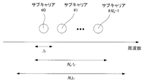
- FIG. 28 is a diagram illustrating a transmission signal including N subcarriers.
- Delta f is the 15kHz if LTE (3.9 generation mobile communication system) with the values determined by the system. This signal is transmitted from the transmission side and sent to the reception side through the propagation path.
- N is the N a may be an integer greater than, but the nature of FFT, to a power of two is common (power of two fastest computable). Since the signal received by the receiver is naturally an analog signal (continuous), filtering and AD conversion are performed so that digital signal processing can be performed.
- FIG. 29 is a diagram illustrating a state in which an analog reception signal is sampled at a time interval ⁇ t .
- ⁇ t corresponds to 1 / (N ⁇ f ).
- the delay time of the delay path is modeled as one that can be handled by an integer multiple of ⁇ t . Therefore, for example, when N is set to 2048 in LTE, the path interval is 0.0326 ⁇ s.
- FIG. 1 is a schematic block diagram of a transmission apparatus according to the first embodiment of the present invention.
- the transmission apparatus according to this embodiment is referred to as a transmission apparatus 301.
- a transmission apparatus 301 includes a pilot generation unit 303, an encoding unit 305, a modulation unit 307, a mapping unit 309, an IFFT unit (also referred to as a frequency time conversion unit) 311, a GI insertion unit 313, a transmission unit 315, and a transmission antenna. 317 and transmit an OFDM signal.
- Pilot generating section 303 generates a pilot symbol in which the receiving apparatus stores in advance the amplitude value of the waveform (or signal sequence thereof), and outputs the pilot symbol to mapping section 309.
- the receiving device is referred to as a receiving device 401.
- Reception apparatus 401 performs propagation path estimation and synchronization using pilot symbols as reference signals.
- the encoding unit 305 encodes information bits to be transmitted to the reception apparatus 401 using an error correction code such as a convolutional code, a turbo code, and an LDPC (Low Density Parity Check) code, Is generated.
- the encoding unit 305 outputs the generated encoded bits to the modulation unit 307.
- the modulation unit 307 modulates the coded bits input from the coding unit 305 using a modulation scheme such as PSK (Phase Shift Keying) or QAM (Quadrature Amplitude Modulation). Generate a symbol.
- Modulation section 307 outputs the generated modulation symbol to mapping section 309.
- the mapping unit 309 maps the pilot symbols input from the pilot generation unit 303 and the modulation symbols input from the modulation unit 307 to resources (time-frequency bands) based on predetermined mapping information. And the generated frequency domain signal is output to the IFFT unit 311.
- a resource is a unit in which a modulation symbol is arranged, which is composed of one subcarrier and one later-described FFT interval in a frame transmitted by the transmission apparatus 301.
- the mapping information is determined by the transmission apparatus 301 and notified from the transmission apparatus 301 to the reception apparatus 401 in advance.
- FIG. 2 is a diagram illustrating an example in which the mapping unit 309 maps pilot symbols and modulated signals.
- the IFFT unit 311 performs frequency-time conversion on the frequency domain signal input from the mapping unit 309 to generate a time domain signal.
- a unit time interval for performing IFFT is referred to as an FFT interval.
- the IFFT unit 311 outputs the generated time domain signal to the GI insertion unit 313.
- the GI insertion unit 313 adds a guard interval (Guard Interval: GI) for each signal in the FFT interval to the time domain signal input from the IFFT unit 311.
- GI Guard Interval
- the guard interval is a known signal or the like using a cyclic prefix (Cyclic Prefix: CP) that is a part of the rear of the signal in the FFT interval, zero padding in which the zero interval continues, Golay code, or the like.
- CP Cyclic Prefix
- the GI insertion unit 313 adds such a signal to the front of the signal in the FFT interval.
- the FFT interval and the time interval (referred to as GI interval) of the guard interval added to the signal in the time interval by the GI insertion unit 313 are collectively referred to as an OFDM symbol interval.
- a signal in the OFDM symbol section is called an OFDM symbol.
- the GI insertion unit 313 outputs a signal with the guard interval added thereto to the transmission unit 315.
- a guard interval may be inserted behind the FFT interval. For example, when a cyclic prefix is used, a part of the replica in front of the FFT interval is added behind the signal in the FFT interval. In the case of a cyclic prefix, the periodicity may be maintained in the OFDM symbol period, and is not limited to the above.
- the transmission unit 315 performs digital / analog conversion on the signal input from the GI insertion unit 313 and shapes the waveform of the converted analog signal.
- the transmission unit 315 up-converts the waveform-shaped signal from the baseband to the radio frequency band, and transmits the signal from the transmission antenna 317 to the reception device 401.
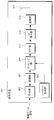
- FIG. 3 is a schematic block diagram showing the configuration of the receiving device 401 according to the first embodiment of the present invention.
- a receiving apparatus 401 includes a receiving antenna 403, a receiving unit 405, a search range determining unit 407, a synchronizing unit 409, a GI removing unit 411, an FFT unit (also referred to as a time frequency converting unit) 413, a demapping unit 415, a propagation A path estimation unit 417, a demodulation unit 419, and a decoding unit 421 are included.
- the reception unit 405 receives the transmission signal transmitted from the transmission device 301 via the reception antenna 403.
- the receiving unit 405 performs frequency conversion and analog-digital conversion on the received signal.
- the search range determination unit 407 determines a path search range from the received signal input from the reception unit 405. This specific processing will be described later together with the operation principle.
- Synchronizing section 409 uses the received signal of the subcarrier to which the pilot symbol is transmitted and the pilot symbol in the search range determined by search range determining section 407 to detect the path that improves the channel suitability and performs synchronization. Do. Details of the synchronization unit 409 will be described later with reference to the drawings. The result is output to the GI removal unit 411.
- the GI removal unit 411 uses the reception signal input from the reception unit 405 and the synchronization information input from the synchronization unit 409, removes the guard interval from the reception signal, and outputs the guard interval to the FFT unit 413.
- the FFT unit 413 performs time-frequency conversion on the time domain signal input from the GI removal unit 411 and outputs the converted frequency domain signal to the demapping unit 415.
- Demapping section 415 performs demapping based on the mapping information notified in advance from transmitting apparatus 301, and outputs the received signal of the subcarrier to which the separated pilot symbol is transmitted to propagation path estimating section 417. In addition, the reception signal of the subcarrier to which data is transmitted is output to demodulation section 419.
- the propagation path estimation unit 417 calculates a demodulation frequency response estimation value using the received signal of the subcarrier to which the pilot symbol is transmitted and the pilot symbol, and outputs the estimated frequency response estimation value to the demodulation unit 419.
- a known technique such as a least square method, MMSE (Minimum Mean Square Error), or DFT (Discrete Fourier Transform) method may be used.
- the propagation path estimation part 417 uses the pilot symbol memorize
- Demodulation section 419 uses the demodulation frequency response estimation value and noise power input from propagation path estimation section 417 to calculate filter coefficients such as a ZF (Zero Forcing) criterion and an MMSE criterion.
- Demodulation section 419 compensates for signal amplitude and phase fluctuations (referred to as propagation path compensation) using the calculated filter coefficients.
- the demodulation unit 419 outputs a bit log likelihood ratio (LLR; Log Likelihood Ratio) as a result of the demodulation process to the decoding unit 421.
- LLR bit log likelihood ratio
- the decoding unit 421 performs, for example, maximum likelihood decoding (MLD; Maximum; Likelihood Decoding), maximum a posteriori probability (MAP), log-MAP, Max ⁇ on the demodulated symbols input from the demodulation unit 419.
- MLD maximum likelihood decoding
- MAP maximum a posteriori probability
- log-MAP log-MAP
- Max ⁇ maximum a posteriori probability
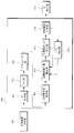
- FIG. 4 is a schematic block diagram showing the configuration of the synchronization unit 409 according to the first embodiment of the present invention.
- the synchronization unit 409 includes a GI removal unit 501, an FFT unit 503, a demapping unit 505, a frequency response estimation unit 507, a channel match calculation unit 509, an unnecessary candidate path removal unit 511, a synchronization correction determination unit 513, and a path extraction unit 515. Consists of This specific processing will be described later together with the operation principle.
- the received signal r i, k of the i-th symbol at the k-th discrete time received by the receiving unit 405 is expressed by the following equations (1) and (2).
- D is the maximum delay time
- h i, d is the complex amplitude in the path of the channel number d of the i-th symbol (referred to as the d-th path)
- s i, k are the time domain of the i-th symbol k-th discrete time. This is a transmission signal
- z i, k is noise in the time domain of the i-th symbol.
- N is the number of points in the FFT interval
- S i, n is the modulation signal of the i-th symbol of the n-th subcarrier
- N g is the number of points in the GI interval (see FIG. 6 described later)
- j is an imaginary unit.
- the received signal at this point is denoted by ru .
- the search range determining section 407 using the correlation between the time waveform of the guard interval correlation and the reference signal using the r u, to locate the previous pass.
- the correlation [rho tau expressed by the following equation (3).
- the width of the sum may be set within a range where a sufficient correlation can be obtained.
- it may be the sum of one OFDM symbol, may be fixed when the receiving apparatus 401 is designed, or may be updated when firmware, software, or the like of the receiving apparatus 401 is updated.
- Figure 5 is a search range determining unit 407 according to the first embodiment of the present invention, is a diagram showing the correlation [rho tau used to identify the position of the previous pass.
- Paths 601 to 619 are strongly correlated parts and are path candidates. Actually, there is also noise, so there are minute values at other positions.
- the path 601 is considered as the preceding path, and this position or a position offset further before is considered as the preceding path position in consideration of the possibility that there is a path that could not be observed at the previous time.
- This offset amount may be fixed when the receiving apparatus 401 is designed, or may be updated when firmware, software, or the like of the receiving apparatus 401 is updated. The offset amount may be zero.
- a threshold value is calculated from a peak value, and a path with a minimum delay time exceeding the threshold value may be set as a preceding path position, or a position offset before the position obtained in this way is used. It may be the preceding path position.
- the preceding path position determined in this way is called a temporary preceding path position.
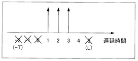
- the search range determination unit 407 also determines a search range for performing synchronization thereafter. Specifically, from the position of the preceding path determined here to a position where the delay time is small by T, a position where the delay time is large by L, that is, the delay time -TL is set as the search range.
- Specific values of T and L may be determined at the stage of designing the receiving device, or may be made variable at the design stage and updated when updating the firmware, software, etc. of the receiving device. Also good. That is, T may be 0.
- L is desirably large enough to cover the maximum delay time, but may be a value similar to T.
- the GI removal unit 501 removes the GI from the received signal based on the preceding path position determined by the search range determination unit 407, and extracts the FFT interval of the received signal. Thereafter, the FFT unit 503 performs time-frequency conversion in the FFT interval of the received signal to convert it to a received signal in the frequency domain. At this time, if the preceding path position determined by the search range determination unit 407 is Ne points before the true position, the signal R i, n of the i-th symbol n-th subcarrier is expressed by the following equation (5). .
- Z i, n, ⁇ Ne is frequency domain noise.
- H i, n, ⁇ Ne is the frequency response of the i-th symbol and the n-th subcarrier , and is expressed by the following equations (6) and (7).
- FIG. 6 shows the signal of the i-th symbol n-th subcarrier when the preceding path position determined by the search range determination unit 407 according to the first embodiment of the present invention is Ne points before the true position.
- the signal R i, n of the i-th symbol n-th subcarrier is expressed by the following equations (8) and (9).
- FIG. 7 shows this state.
- N e As a result of shifting back by N e , ISI and ICI occur because the preceding path portion 801 is a different OFDM symbol. For this reason, transmission characteristics deteriorate.
- the frequency response of the i-th symbol n-th subcarrier will be described as Hi, n .
- n 1 , n 2 ,..., n P are pilot subcarriers, and frequency response estimation vectors H i, P are defined as in the following equation (10).
- n 1 is the lowest subcarrier
- n 2 is the next subcarrier
- n 3 is the next subcarrier
- N P is the number of pilot subcarriers
- I x is the identity matrix of size x.
- the delay time -T to L represents the search range, and is determined by the search range determination unit 407 determining the preceding path position. A negative delay time is also taken into consideration from the position of the preceding path, and -T is considered. L is an assumed maximum delay time.
- C i, h is a diagonal matrix of size L + T + 1 having the value of the average power of paths from ⁇ T to L as main diagonal elements. Since the average power is unknown, a constant value ⁇ is used. However, only a path that improves the channel matching degree is set to ⁇ , and other paths are set to 0.
- the channel adaptability is a quantity that quantitatively represents the adaptability between the calculated estimated value and the observed data (received signal here).
- FIG. 8 is a diagram showing the average power of each path according to the first embodiment of the present invention.
- C i, h is expressed by the following equation (15).
- the preceding path position is set.
- the search range determination unit 407 shifts by the detected amount from that determined. The shift is also performed when the path with the shortest delay time that improves the channel adaptability is in the positive delay time.
- the propagation path adaptability calculation unit 509 uses the frequency response estimation value input from the frequency response estimation unit 507, and in addition to the paths extracted so far, increases one path among candidate paths to generate a channel impulse response. presume. This is performed for all candidate paths, and the propagation path suitability is calculated for each. However, since there is no extracted path in the first process, one-path estimation with all candidate paths is performed to calculate the propagation path adaptability.
- FIG. 9 is a diagram for explaining one-path estimation using all candidate paths according to the first embodiment of the present invention.
- the unnecessary candidate path removal unit 511 deletes, from the candidate paths, a path that has fallen below the propagation path fitness before increasing the number of paths from the input from the propagation path fitness calculation section 509.
- this deletion processing is not performed.
- the synchronization correction determination unit 513 detects that there is no candidate path having a delay time shorter than the extracted path having the shortest delay time, the synchronization correction determination unit 513 ends the process of the synchronization unit 409.
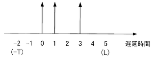
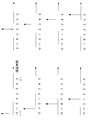
- FIGS. 10A to 10C are diagrams illustrating average power of each path after the processing of the synchronization unit 409 according to the first embodiment of the present invention is completed.
- FIG. 10 shows a case where three passes are selected after the processing of the synchronization unit 409 is completed.
- the position where the path stands represents the path extracted by the processing so far, and the position marked with x represents the deleted candidate path.
- FIG. 10A shows an example in which the same path as the synchronization position determined by the search range determination unit 407 is the preceding path. In this case, the synchronization position does not change.
- FIG. 10B shows an example in which a path is detected at a negative delay time. It is considered that the problem shown in FIG.
- FIG. 10C is an example when it is detected that the synchronization has shifted in the positive direction. As described above, since the problem as shown in FIG. 6 may occur, the shift is also performed in this case.
- the shift amount (here, 1) is output to the GI removal unit 411.
- the synchronization correction determination unit 513 does not particularly operate and moves to the path extraction unit 515.
- the path extraction unit 515 extracts a path that maximizes the propagation path suitability from candidate paths that have not been removed by the unnecessary candidate path removal unit 511.
- the extracted path position is removed from the candidate paths, and the extracted path information is output to the propagation path fitness calculation unit 509.
- the synchronization unit 409 repeats these processes until the synchronization correction determination unit 513 determines the shift amount.
- Akaike Information Criterion (AIC), Bayesian Information Criterion (BIC), Minimum Description Length (MDL) may be used for propagation path conformity, For example, model evidence derived from the pilot structure of FIG. 2 may be used.
- the propagation path adaptability when using a BIC is expressed by the following equation (16). However, N s is the number of paths extracted up to that point.
- the GI removal unit 411 removes the GI from the reception signal input from the reception unit 405 based on the synchronization position determined by the synchronization unit 409.
- the FFT unit 413 performs time-frequency conversion to convert the received signal in the frequency domain.
- the channel response estimation unit 417 estimates the frequency response and uses it as a demodulation frequency response.
- the demodulation unit 419 calculates a demodulation symbol S ′ i, n as shown in the following equation (17), for example, when filtering based on MMSE is used.
- ⁇ z 2 is the power of Z i, n and is expressed as in the following equation (18).
- E [X] represents an ensemble average of X. This power can be calculated as in the following equation (19), and the result is used in equation (17) to calculate the demodulated symbol S ′ i, n .
- ⁇ z ′ 2 is an estimated value of ⁇ z 2
- P i is a set representing pilot subcarriers in the i-th symbol. Note that this is a calculation method that utilizes the fact that equation (19) can be expressed by the following equation (20), assuming that a sufficient number of arithmetic averages are equal to the ensemble average.
- This equation is for the case where the pilot symbol power is normalized to 1 and the frequency response power average is normalized to 1. That is, this equation is a case where the following equation (21) is satisfied.
- the demodulator 419 calculates a bit log likelihood ratio from the demodulated symbol S ′ i, n in Expression (17).
- An equivalent amplitude gain is used for this calculation process.
- the bit log likelihood ratio ⁇ is expressed by the following equations (23) and (24) with respect to the equivalent amplitude gain ⁇ i, n of the n-th subcarrier expressed by the following equation (22).
- Equation (23) and (24) are respectively expressed as the bit log likelihood ratios ⁇ (b i, n ) of the first bit b i, n, 0 and the second bit b i, n, 1. , 0 ), ⁇ (b i, n, 1 ).
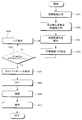
- FIG. 11 is a flowchart showing the operation of the receiving apparatus according to the first embodiment of the present invention.
- the operation shown in this figure is processing after the reception unit 405 in FIG. 3 outputs the received signal to the search range determination unit 407.
- the search range determination unit 407 determines a previous path position and a search range for synchronization from the received signal (step S101). Then, it progresses to step S102.
- the frequency response estimation unit 507 estimates the frequency response of the pilot subcarrier using the received signal that has been time-frequency converted based on the preceding path position determined in step S101, and sets the frequency response estimated value (step S102). Thereafter, the process proceeds to step S103.
- the channel adaptation calculation unit 509 uses the frequency response estimation value obtained in step S102, and in addition to the paths determined so far by the path extraction unit 515, the channel impulse response when one of the candidate paths is added. Is estimated (step S103). This process is performed as many times as the number of candidate paths, and the channel adaptability is calculated for each. Thereafter, the process proceeds to step S104.
- Unnecessary candidate path removal unit 511 removes, from the candidate paths, paths corresponding to the degree of propagation path adaptation obtained in step S103 that is lower than the degree of propagation path adaptation before adding one path (step S104). Thereafter, the process proceeds to step S105, and synchronization correction determination is performed.
- the synchronization correction determination unit 513 determines the shift amount to be applied to the synchronization position when there is no candidate path having a delay time shorter than the path having the smallest delay time among the extracted paths (step S105: Yes). Determine and proceed to step S107. When that is not right (step S105: No), it progresses to step S106.
- the path extraction unit 515 determines, as an extraction path, a path corresponding to the largest of the propagation path adaptability of candidate paths remaining as a result of step S104 (step S106). Thereafter, the process returns to step S103.
- the GI removal unit 411 removes the guard interval from the received signal based on the synchronization position determined in step S105 (step S107). Thereafter, the process proceeds to step S108.
- the FFT unit 413 performs time-frequency conversion on the signal obtained in step S107 (step S108).
- the demapping unit 415 separates data and pilot symbols from the obtained frequency domain signal.
- the reception signal of the pilot subcarrier is output to propagation path estimation section 417. Thereafter, the process proceeds to step S109.
- Propagation path estimation section 417 performs propagation path estimation using the pilot subcarrier received signal obtained in step S108, and outputs a demodulation frequency response estimation value to demodulation section 419 (step S109). Then, it progresses to step S110.
- Demodulation section 419 performs demodulation using the reception signal of the data subcarrier obtained in step S108 and the frequency response estimation value for demodulation obtained in step S109 (step S110). Thereafter, the process proceeds to step S111.
- the decoding unit 421 performs decoding using the demodulation result obtained in step S110 (step S111). Thereafter, the receiving device 401 ends the operation.
- the synchronization unit 409 estimates the frequency response of the pilot subcarrier, deletes the path that cannot improve the channel suitability from the candidate paths, and improves the channel match.
- the process of extracting the path is repeated, and the process is terminated when there is no candidate path having a delay time that is further shorter than that of the extracted path having the shortest delay time. At this time, if the extracted path with the smallest delay time is not the path with the delay time 0, synchronization correction is performed. In this way, since the path is selected and estimated, the noise and interference reduction effect is increased, and noise enhancement can be suppressed.
- the frequency response is estimated using the pilot symbol for each OFDM symbol and the shift amount with respect to the synchronization position determined by the search range determination unit 407 is described.
- the position of the pilot subcarrier is the lowest subcarrier, the second subcarrier, the second subcarrier, and so on.
- Locations that are not subcarriers may also be estimated using pilot symbols of OFDM symbols having different times.
- noise and interference can be reduced by using pilot symbols at different times. In this way, the synchronization correction accuracy can be further improved.
- an arithmetic average may be performed, or a weighted average may be performed according to the propagation path fluctuation.
- pilot symbols are used as reference signals used for frequency response estimation
- estimation may be performed using determined data. Specifically, it can be realized by feeding back the output of the demodulator 419 or the decoder 421 to the frequency response estimator 507.
- a case has been described in which channel impulse responses are estimated by adding candidate paths, and a path that improves the channel suitability is extracted most. Good. For example, three paths may be selected in descending order of improvement, or a condition may be added that these three paths do not select ones with a short delay time. For example, in the case of processing delay times -2 to 5 as shown in FIG. 8, if the path extraction unit 515 selects a path with a delay time of 0, two neighboring paths (-2, -1, 1, 1, 2) are It can be realized by not selecting at the same time.
- the method of detecting a path up to the delay time L and performing synchronization correction has been described.
- the number of candidate paths may be limited in advance by another method.
- the frequency response estimation value obtained by the frequency response estimation unit 507 is subjected to frequency time conversion, and only the position where the power is high is left as a candidate path among the obtained temporary estimation values of the channel impulse response. Processing after the calculation unit 509 is performed.
- the path position exists at the sampling position of the received signal as in Expression (1). However, the interval between the sampling points may be considered. In that case, the Fourier transform matrix of Equation (13) includes the decimal point position.
- FIG. 12 is a diagram showing a path structure when the path position exists between the sampling position of the received signal and the sampling point in the first embodiment of the present invention.
- the Fourier transform matrix is as shown in the following equation (25).
- the communication system has been described for multi-carrier signal communication.
- the present invention is not limited to this and is also applicable to single-carrier signal communication using FFT. can do.
- the transmission device 301 transmits a multicarrier signal or the like that maps pilot symbols in the frequency domain, and the reception device 401 calculates a frequency response estimation value in the pilot subcarrier, and estimates a channel impulse response.
- the paths that improve the channel adaptability are selected one by one, and the synchronization correction amount is determined when the necessity of synchronization correction is determined.
- the transmission apparatus according to the present embodiment has the same configuration as the transmission apparatus 301 according to the first embodiment, and thus description thereof is omitted.
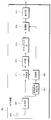
- FIG. 13 is a schematic block diagram showing the configuration of the receiving device 901 according to the second embodiment of the present invention. Comparing the receiving apparatus 901 according to the present embodiment (FIG. 13) and the receiving apparatus 401 according to the first embodiment (FIG. 3), it does not have the propagation path estimation unit 417, and the operation of the synchronization unit 903 is the synchronization unit 409. And different. However, the functions of other components (receiving antenna 403, receiving unit 405, search range determining unit 407, GI removing unit 411, FFT unit 413, demapping unit 415, demodulation unit 419, decoding unit 421) are the first This is the same as the embodiment. A description of the same functions as those in the first embodiment is omitted. Note that, unlike the first embodiment, the value set to L is preferably a value that can cover the maximum delay time.
- FIG. 14 is a schematic block diagram showing the configuration of the synchronization unit 903 according to the second embodiment of the present invention.
- the operation of the synchronization correction determination unit 1001 is different, and the FFT unit 1003 (propagation time) Also called a frequency converter).
- the functions of other components GI removal unit 501, FFT unit 503, demapping unit 505, frequency response estimation unit 507, channel match calculation unit 509, unnecessary candidate path removal unit 511, path extraction unit 515) Is the same as in the first embodiment.
- a description of the same functions as those in the first embodiment is omitted.
- the shift amount is determined and the operation of the synchronization unit 409 is terminated. I was letting.
- the shift amount is determined, and the estimated value of the channel impulse response of Equation (11) estimated simultaneously is calculated by the FFT unit 1003. Output to.
- the FFT unit 1003 performs time-frequency conversion on the channel impulse response estimation value input from the synchronization correction determination unit 1001 to convert it to a frequency response estimation value. At this time, the time frequency conversion is performed after the shift amount determined by the synchronization correction determination unit 1001 is reflected in the channel impulse response. The result is output to demodulation section 419.
- FIG. 15 is a flowchart showing the operation of the receiving apparatus according to the second embodiment of the present invention.
- the operation shown in this figure is a process after the reception unit 405 in FIG. 13 outputs a reception signal to the search range determination unit 407.
- the search range determination unit 407 determines a previous path position and a search range for synchronization from the received signal (step S201). Thereafter, the process proceeds to step S202.
- the frequency response estimation unit 507 estimates the frequency response of the pilot subcarrier using the received signal subjected to time-frequency conversion based on the preceding path position determined in step S201, and sets the frequency response estimated value (step S202). Then, it progresses to step S203.
- the channel adaptation calculation unit 509 uses the frequency response estimation value obtained in step S202, and in addition to the path determined by the path extraction unit 515, the channel impulse response when one of the candidate paths is added. Is estimated. This process is performed as many times as the number of candidate paths, and the channel adaptability is calculated (step S203). Thereafter, the process proceeds to step S204.
- the unnecessary candidate path removal unit 511 removes, from the candidate paths, paths corresponding to the degree of propagation path adaptation obtained in step S203 that is lower than the degree of propagation path adaptation before adding one path (step S204). Thereafter, the process proceeds to step S205, and synchronization correction determination is performed.
- the synchronization correction determination unit 1001 determines the shift amount to be applied to the synchronization position and uses the estimated channel impulse response estimated value as the frequency. After converting to the response estimated value, the response is output to the demodulator 419, and the process proceeds to step S207. When that is not right (step S205: No), it progresses to step S206.
- the path extraction unit 515 determines, as an extraction path, a path corresponding to the largest of the propagation path adaptability of candidate paths remaining as a result of step S204 (step S206). Then, it returns to step S203.
- GI removal unit 411 removes the guard interval from the received signal based on the synchronization position determined in step S205 (step S207). Thereafter, the process proceeds to step S208.
- the FFT unit 413 performs time-frequency conversion on the signal obtained in step S207 (step S208).
- the demapping unit 415 separates data and pilot symbols from the obtained frequency domain signal. Thereafter, the process proceeds to step S209.
- Demodulation section 419 performs demodulation using the data subcarrier received signal obtained in step S208 and the demodulation frequency response estimation value obtained in step S205 (step S209). Thereafter, the process proceeds to step S210.
- the decoding unit 421 performs decoding using the demodulation result obtained in step S209 (step S210). Thereafter, the receiving device 901 ends the operation.
- the propagation path estimation is performed at the same time in the process of the synchronization section 903, the propagation path estimation section is not required, so that the circuit scale can be reduced.
- the transmission apparatus 301 transmits a multicarrier signal or the like that maps pilot symbols in the frequency domain, and the reception apparatus 401 or the reception apparatus 901 calculates a frequency response estimation value in the pilot subcarrier.
- the synchronization correction amount is determined by selecting one path at a time for improving the channel adaptability using channel impulse response estimation by MMSE.
- transmitting apparatus 1101 performs single carrier transmission for transmitting a continuous signal in the time domain, inserts a pilot symbol that is continuous in time, and performs synchronization correction using the pilot symbol as a reference signal. The case will be described.
- FIG. 16 is a schematic block diagram illustrating a configuration of a transmission device 1101 according to the third embodiment of the present invention.
- the mapping unit 1103 does not have the IFFT unit 311 and the GI insertion unit 313. Is different.
- the functions of other components are the same as those in the first or second embodiment. The description of the same function as in the first or second embodiment is omitted.
- Mapping section 1103 generates a time-domain signal by mapping pilot symbols input from pilot generation section 303 and modulation symbols input from modulation section 307 to the time domain based on predetermined mapping information.
- the generated time domain signal is output to the transmission unit 315.
- the mapping information is determined by the transmission apparatus 1101 and notified in advance from the transmission apparatus 1101 to the reception apparatus 1201 (the reception apparatus according to the third embodiment of the present invention is the reception apparatus 1201).
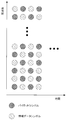
- FIG. 17 is a diagram illustrating an example in which the mapping unit 1103 according to the third embodiment of the present invention maps information data symbols and pilot symbols.
- white squares represent information data symbols
- shaded squares represent pilot symbols.
- the pilot symbols are transmitted in K symbol sequences.
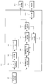
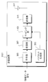
- FIG. 18 is a schematic block diagram showing the configuration of the receiving device 1201 according to the third embodiment of the present invention.
- the receiving apparatus 1201 (FIG. 18) according to the present embodiment is compared with the receiving apparatus 401 (FIG. 3) according to the first embodiment, the GI removing unit 411 and the FFT unit 413 are not included, and the synchronizing unit 1203, the propagation path
- the estimation unit 1205, the demodulation unit 1207, and the demapping unit 1209 are different.
- the functions of other components (receiving antenna 403, receiving unit 405, search range determining unit 407, decoding unit 421) are the same as those in the first embodiment. A description of the same functions as those in the first embodiment is omitted.
- FIG. 19 is a schematic block diagram showing the configuration of the synchronization unit 1203 according to the third embodiment of the present invention.
- the GI removal unit 501, the FFT unit 503, and the frequency response estimation unit 507 are not included, and the processing of the demapping unit 1301 and the propagation path fitness calculation unit 1303 is performed. Is different.
- the functions of other components are the same as those in the first embodiment. A description of the same functions as those in the first embodiment is omitted.
- the propagation path fitness calculation unit 1303 uses a reception signal corresponding to the time at which the pilot symbol input from the demapping unit 1301 is transmitted, and in addition to the paths extracted so far, one path among the candidate paths To estimate the channel impulse response.
- this is the same as the propagation path fitness calculation unit 509 in the first embodiment.
- the demapping unit 1209 performs demapping based on the mapping information notified in advance from the transmission device 1101, outputs a received signal corresponding to the time when the separated pilot symbol is transmitted to the propagation path estimation unit 1205, and the data is A received signal corresponding to the transmitted time is output to demodulation section 1207.
- the propagation path estimation unit 1205 calculates a channel impulse response estimated value using the received signal corresponding to the time at which the pilot symbol is transmitted and the pilot symbol, and outputs the channel impulse response estimated value to the demodulation unit 1207.
- the least square method or MMSE may be used as in the first embodiment, or a channel impulse response using an RLS (Recursive Least Squares) algorithm, an LMS (Least Mean Square) algorithm, or the like.
- Demodulation section 1207 performs demodulation processing using the received signal input from demapping section 1209 and the channel impulse response estimation value input from propagation path estimation section 1205. At this time, ISI due to multipath is compensated.
- a known technique such as MMSE or MLSE (Maximum Likelihood Sequence Estimation: MaximumMaxLikelihood SequencetimEstimation) may be used.
- FIG. 20 is a flowchart showing the operation of the receiving apparatus according to the third embodiment of the present invention.
- the operation shown in this figure is processing after the reception unit 405 in FIG. 18 outputs the reception signal to the search range determination unit 407.
- the search range determination unit 407 determines the previous path position and the search range for synchronization from the received signal (step S301). Thereafter, the process proceeds to step S302.
- the propagation path adaptability calculation unit 1303 Based on the preceding path position determined in step S301, the propagation path adaptability calculation unit 1303 generates a channel impulse response when one of the candidate paths is added to the paths previously determined by the path extraction unit 515. presume. This process is performed as many times as the number of candidate paths, and propagation path fitness is calculated for each (step S302).
- step S303 The unnecessary candidate path removal unit 511 removes, from the candidate paths, paths corresponding to the propagation path fitness obtained in step S302 that is lower than the propagation path fitness before adding one path (step S303). Thereafter, the process proceeds to step S304, and synchronization correction determination is performed.
- step S303 the synchronization correction determination unit 513 determines the shift amount to be applied to the synchronization position when there is no candidate path with a delay time smaller than the path with the smallest delay time among the extracted paths (step S304: Yes). Determine and proceed to step S306. Otherwise (step S304: No), the process proceeds to step S305.
- the path extraction unit 515 determines, as an extraction path, a path corresponding to the largest of the propagation path adaptability of candidate paths remaining as a result of step S303 (step S305). Thereafter, the process returns to step S302.
- the demapping unit 1209 separates data and pilot symbols from the received signal based on the synchronization position determined in step S304.
- a reception signal corresponding to the time when the separated pilot symbol is transmitted is output to propagation path estimation section 1205, and a reception signal corresponding to the time when data is transmitted is output to demodulation section 1207.
- propagation path estimation section 1205 estimates the channel impulse response and outputs it to demodulation section 1207 (step S306). Thereafter, the process proceeds to step S307.
- Demodulation section 1207 performs demodulation using the received signal corresponding to the time at which the data obtained in step S306 was transmitted and the channel impulse response estimated value (step S307). Thereafter, the process proceeds to step S308.
- the decoding unit 421 performs decoding using the demodulation result obtained in step S307 (step S308). Thereafter, the receiving apparatus 1201 ends the operation.
- the synchronization unit 1203 uses the received signal corresponding to the time when the pilot symbol is transmitted, deletes the path that cannot improve the propagation path suitability from the candidate paths, and transmits the propagation path.
- the process of extracting a path that improves the fitness is repeated, and the process is terminated when there are no candidate paths with a smaller delay time than those with the smallest delay time among the extracted paths.
- synchronization correction is performed.
- the reception device 401 according to the first embodiment may be used as a reception process for the signal transmitted by the transmission device 301 according to the present embodiment.
- the signal may be processed as a signal having a GI interval of 0.
- the transmission apparatus 1101 transmits a single carrier signal or the like that maps pilot symbols in the time domain, and the reception apparatus 1201 uses a reception signal corresponding to the time at which the pilot symbols are transmitted, and uses a channel impulse response.
- the path for improving the channel adaptability is selected one by one using the above estimation, and the synchronization correction amount is determined when the necessity of synchronization correction is determined.
- the transmission device according to the present embodiment has the same configuration as the transmission device 1101 according to the third embodiment, and thus description thereof is omitted.
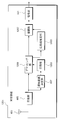
- FIG. 21 is a schematic block diagram showing a configuration of a receiving device 1401 according to the fourth embodiment of the present invention.
- the receiving apparatus 1401 (FIG. 21) according to the present embodiment is compared with the receiving apparatus 1201 (FIG. 18) according to the third embodiment, the channel estimation unit 1205 is not provided, and the operation of the synchronization unit 1403 is the synchronization unit 1203. And different.
- the functions of other components (receiving antenna 403, receiving unit 405, search range determining unit 407, demapping unit 1209, demodulating unit 1207, and decoding unit 421) are the same as those in the third embodiment. A description of the same functions as those in the third embodiment is omitted.
- FIG. 22 is a schematic block diagram showing the configuration of the synchronization unit 1403 according to the fourth embodiment of the present invention.
- the second embodiment is used instead of the synchronization correction determination unit 513 in the first embodiment. It has a synchronization correction determination unit 1001 in the form.
- the functions of the other components are the same as those in the third embodiment. A description of the same functions as those in the third embodiment is omitted.
- FIG. 23 is a flowchart showing the operation of the receiving apparatus according to the fourth embodiment of the present invention.
- the operation shown in this figure is processing after the receiving unit 405 in FIG. 21 outputs the received signal to the search range determining unit 407.
- the search range determination unit 407 determines a previous path position and a search range for synchronization from the received signal (step S401). Thereafter, the process proceeds to step S402.
- the propagation path adaptability calculation unit 1303 Based on the preceding path position determined in step S401, the propagation path adaptability calculation unit 1303 generates a channel impulse response when one of the candidate paths is added to the paths previously determined by the path extraction unit 515. presume.
- step S402 This process is performed as many times as the number of candidate paths, and propagation path suitability is calculated for each (step S402). Thereafter, the process proceeds to step S403.
- the unnecessary candidate path removal unit 511 removes, from the candidate paths, paths corresponding to the propagation path fitness obtained in step S402 that is lower than the propagation path fitness before adding one path (step S403). Thereafter, the process proceeds to step S404, and synchronization correction determination is performed.
- step S403 If the result of step S403 is that the remaining candidate paths become zero (step S404: Yes), the synchronization correction determination unit 1001 determines the shift amount to be applied to the synchronization position and demodulates the estimated channel impulse response estimation value. The data is output to the unit 1207, and the process proceeds to step S406. When that is not right (step S404: No), it progresses to step S405.
- the path extraction unit 515 determines, as an extraction path, a path corresponding to the largest of the propagation path adaptability of candidate paths remaining as a result of step S403 (step S405). Thereafter, the process returns to step S402.
- the demapping unit 1209 separates data and pilot symbols from the received signal based on the synchronization position determined in step S404.
- a reception signal corresponding to the time when the separated data is sent is output to demodulation section 1207.
- Demodulation section 1207 performs demodulation using this received signal and the channel impulse response estimated value obtained in step S404 (step S406). Thereafter, the process proceeds to step S407.
- the decoding unit 421 performs decoding using the demodulation result obtained in step S406 (step S407). Thereafter, the receiving apparatus 1401 ends the operation.
- the propagation path estimation is performed simultaneously with the processing of the synchronization section 1403, it is not necessary to have the propagation path estimation section, so that the circuit scale can be reduced.
- the transmitter 301 transmits a multicarrier signal or the like that maps pilot symbols in the frequency domain, and the receiver 401 first determines the frequency in the pilot subcarrier based on the determined search range and the preceding path position. A response estimation value is calculated, and a path for improving the channel adaptability is selected one by one using the estimation of the channel impulse response, and the synchronization amount is determined when the remaining candidate paths become zero.
- the transmission apparatus according to the present embodiment has the same configuration as the transmission apparatus 301 according to the first embodiment, and thus description thereof is omitted.
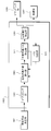
- FIG. 24 is a schematic block diagram illustrating a configuration of a reception device 1501 according to the fifth embodiment of the present invention. Comparing the receiving apparatus 1501 (FIG. 24) according to the present embodiment with the receiving apparatus 901 (FIG. 13) according to the second embodiment, the configuration of the search range determining unit 1503 is different, and a plurality of synchronizing units 903 are provided, A road suitability determination unit 1505 is added. However, the functions of other components (receiving antenna 403, receiving unit 405, GI removing unit 411, FFT unit 413, demapping unit 415, demodulating unit 419, decoding unit 421) are the same as those in the second embodiment. . A description of the same functions as those in the second embodiment is omitted.
- the search range determination unit 1503 sets a plurality of preceding path positions, and determines a search range for each as in the first to fourth embodiments. This setting method is, for example, as shown in FIG.
- FIG. 25 is a diagram for explaining a setting method for setting a plurality of preceding path positions according to the fifth embodiment of the present invention.
- two types of search ranges are set.
- the position 1601 is the head of the first search range
- the position 1603 is the first preceding path position
- the position 1605 is the end of the first search range.
- a position 1611 represents the head of the first search range
- a position 1613 represents the first preceding path position
- a position 1615 represents the end of the first search range.
- a plurality of synchronization units 903 perform the same processing as in the second embodiment on the plurality of search ranges output by the search range determination unit 1503.
- the propagation path match determination unit 1505 selects the one with the highest propagation path match input from the plurality of synchronization units 903, outputs the corresponding synchronization position to the GI removal unit 411, and demodulates the channel impulse response estimation value. Output to.
- FIG. 26 is a flowchart showing the operation of the receiving apparatus according to the fifth embodiment of the present invention.
- the operation shown in this figure is processing after the receiving unit 405 in FIG. 24 outputs the received signal to the search range determining unit 1503.
- Search range determining section 1503 determines a plurality of preceding path positions and a search range for synchronization from the received signal (step S501). Thereafter, the process proceeds to step S502.
- the plurality of frequency response estimators 507 estimate the frequency response of the pilot subcarriers using the received signals that have been time-frequency converted based on the plurality of preceding path positions determined in step S501 to obtain frequency response estimated values (step S502). Thereafter, the process proceeds to step S503.
- the plurality of propagation path fitness calculation units 509 use one of the candidate paths in addition to the paths determined so far by the corresponding path extraction unit 515 using the plurality of frequency response estimation values obtained in step S502.
- the channel impulse response is estimated. This process is performed as many times as the number of candidate paths, and the channel adaptability is calculated (step S503). Thereafter, the process proceeds to step S504.
- the plurality of unnecessary candidate path removal units 511 remove, from the candidate paths, paths corresponding to those that are less than the corresponding channel match before adding one path among the plurality of channel match obtained in step S503. (Step S504). Thereafter, the process proceeds to step S505.
- the plurality of synchronization correction determination units 1001 determine the shift amount to be applied to the synchronization position and output it to the propagation path adaptation determination unit 1505.
- the estimated channel impulse response estimated value is output to the propagation path match determination unit 1505, and the operation ends. If all the synchronization correction determination units 1001 have finished their operations (step S505: Yes), the process proceeds to step S507.
- step S505 When that is not right (step S505: No), it progresses to step S506.
- the plurality of path extraction units 515 determine, as an extraction path, a path corresponding to the largest of the propagation path adaptability of candidate paths remaining as a result of step S504 (step S506). Thereafter, the process returns to step S503.
- the propagation path adaptation determination unit 1505 outputs the synchronization position corresponding to the largest one of the plurality of propagation path adaptations obtained as a result of step S505 to the GI removal unit 411, and the channel impulse response estimated value is the frequency response estimated value. And then output to the demodulator 419 (step S507). Thereafter, the process proceeds to step S508.
- the GI removal unit 411 removes the guard interval from the received signal based on the synchronization position determined in step S507 (step S508). Thereafter, the process proceeds to step S509.
- the FFT unit 413 performs time-frequency conversion on the signal obtained in step S508 (step S509).
- the demapping unit 415 separates data and pilot symbols from the obtained frequency domain signal.
- step S510 Demodulation section 419 performs demodulation using the received data subcarrier signal obtained in step S509 and the demodulation frequency response estimation value obtained in step S507 (step S510). Thereafter, the process proceeds to step S511.
- the decoding unit 421 performs decoding using the demodulation result obtained in step S510 (step S511). Thereafter, the receiving apparatus 1501 ends the operation.
- a plurality of synchronization units determine a synchronization position, and a position that can improve transmission characteristics is selected as the synchronization position by selecting the largest one of the propagation path suitability levels. be able to.
- a part of the transmission devices 301 and 1101 and the reception devices 401, 901, 1201, and 1301, for example, the synchronization unit 409 and the demodulation unit 419 in the above-described embodiment may be realized by a computer.
- a program for realizing this control function may be recorded on a computer-readable recording medium, and the program recorded on this recording medium may be read into a computer system and executed.
- the “computer system” here is a computer system built in the transmission apparatuses 301 and 1101 or the reception apparatuses 401, 901, 1201, and 1301, and includes hardware such as an OS and peripheral devices.
- the “computer-readable recording medium” refers to a storage device such as a portable medium such as a flexible disk, a magneto-optical disk, a ROM, and a CD-ROM, and a hard disk built in the computer system.
- the “computer-readable recording medium” is a medium that dynamically holds a program for a short time, such as a communication line when transmitting a program via a network such as the Internet or a communication line such as a telephone line,
- a volatile memory inside a computer system serving as a server or a client may be included and a program that holds a program for a certain period of time.
- the program may be a program for realizing a part of the functions described above, and may be a program capable of realizing the functions described above in combination with a program already recorded in a computer system.
- a part or all of the transmission devices 301 and 1101 and the reception devices 401, 901, 1201, and 1301 in the above-described embodiments may be realized as an integrated circuit such as an LSI (Large Scale Integration).
- LSI Large Scale Integration
- Each functional block of the transmission device 301 and the reception devices 401, 901, and 1201 may be individually made into a processor, or a part or all of them may be integrated into a processor.
- the method of circuit integration is not limited to LSI, and may be realized by a dedicated circuit or a general-purpose processor. Further, in the case where an integrated circuit technology that replaces LSI appears due to progress in semiconductor technology, an integrated circuit based on the technology may be used.
Landscapes
- Engineering & Computer Science (AREA)
- Computer Networks & Wireless Communication (AREA)
- Signal Processing (AREA)
- Power Engineering (AREA)
- Noise Elimination (AREA)
Abstract
L'objectif de la présente invention est de permettre une détermination à haute précision d'une position de synchronisation. La présente invention porte sur un dispositif récepteur servant à déterminer une position de trajet antérieure sur la base d'un signal à trajets multiples reçu, qui comprend : une unité de calcul d'accord de trajet de propagation (509) qui estime une réponse impulsionnelle de canal à l'aide d'une estimation de réponse en fréquence de manière à calculer, pour chaque trajet, un accord de trajet de propagation indiquant l'accord entre l'estimation et le trajet ; une unité d'élimination de trajets candidats non nécessaires (511) pour éliminer des trajets candidats qui n'augmentent pas l'accord de trajet de propagation ; une unité d'extraction de trajet (515) pour extraire au moins un trajet candidat qui augmente l'accord de trajet de propagation de manière à le considérer comme trajet extrait ; et une unité d'évaluation de correction de synchronisation (513) qui détermine la position temporelle du trajet candidat pour lequel le retard est le plus petit parmi les trajets extraits à titre de position de trajet antérieure.
Applications Claiming Priority (2)
| Application Number | Priority Date | Filing Date | Title |
|---|---|---|---|
| JP2011126672A JP2012253688A (ja) | 2011-06-06 | 2011-06-06 | 受信装置、受信方法、制御プログラムおよび集積回路 |
| JP2011-126672 | 2011-06-06 |
Publications (1)
| Publication Number | Publication Date |
|---|---|
| WO2012169303A1 true WO2012169303A1 (fr) | 2012-12-13 |
Family
ID=47295874
Family Applications (1)
| Application Number | Title | Priority Date | Filing Date |
|---|---|---|---|
| PCT/JP2012/061736 Ceased WO2012169303A1 (fr) | 2011-06-06 | 2012-05-08 | Dispositif récepteur, procédé de réception, programme de commande et circuit intégré |
Country Status (2)
| Country | Link |
|---|---|
| JP (1) | JP2012253688A (fr) |
| WO (1) | WO2012169303A1 (fr) |
Families Citing this family (1)
| Publication number | Priority date | Publication date | Assignee | Title |
|---|---|---|---|---|
| RU2721157C1 (ru) * | 2017-03-24 | 2020-05-18 | Телефонактиеболагет Лм Эрикссон (Пабл) | Широкополосное обнаружение сигнала синхронизации в системе nr |
Citations (2)
| Publication number | Priority date | Publication date | Assignee | Title |
|---|---|---|---|---|
| JP2003319005A (ja) * | 2002-02-20 | 2003-11-07 | Mitsubishi Electric Corp | シンボルタイミング補正回路、受信機、シンボルタイミング補正方法、及び復調処理方法 |
| JP2005065197A (ja) * | 2003-08-20 | 2005-03-10 | Rikogaku Shinkokai | 高精度タイミング再生を備えたmimo−ofdm受信方式および受信機 |
-
2011
- 2011-06-06 JP JP2011126672A patent/JP2012253688A/ja not_active Withdrawn
-
2012
- 2012-05-08 WO PCT/JP2012/061736 patent/WO2012169303A1/fr not_active Ceased
Patent Citations (2)
| Publication number | Priority date | Publication date | Assignee | Title |
|---|---|---|---|---|
| JP2003319005A (ja) * | 2002-02-20 | 2003-11-07 | Mitsubishi Electric Corp | シンボルタイミング補正回路、受信機、シンボルタイミング補正方法、及び復調処理方法 |
| JP2005065197A (ja) * | 2003-08-20 | 2005-03-10 | Rikogaku Shinkokai | 高精度タイミング再生を備えたmimo−ofdm受信方式および受信機 |
Non-Patent Citations (2)
| Title |
|---|
| KATSUYA KATO ET AL.: "Channel Estimation Employing Highly Efficient Tap Selection based on Information Criterion for OFDM Turbo Equalization", IEICE TECHNICAL REPORT, THE INSTITUTE OF ELECTRONICS, INFORMATION AND COMMUNICATION ENGINEERS, 23 February 2011 (2011-02-23), pages 55 - 60 * |
| TAKAYUKI SHIZUNO ET AL.: "An Accurate Timing Recovery Method Employing Channel Estimation for OFDM Packet Transmission", IEICE TECHNICAL REPORT, THE INSTITUTE OF ELECTRONICS, INFORMATION AND COMMUNICATION ENGINEERS, 15 August 2003 (2003-08-15), pages 41 - 46 * |
Also Published As
| Publication number | Publication date |
|---|---|
| JP2012253688A (ja) | 2012-12-20 |
Similar Documents
| Publication | Publication Date | Title |
|---|---|---|
| US7933366B2 (en) | Channel estimation method and system using linear correlation based interference cancellation (LCIC) combined with decision-feedback-equalization (DFE) | |
| JP2012142932A (ja) | 狭帯域干渉を受けるofdm信号を復号する方法 | |
| WO2008006246A1 (fr) | Procédé et système de multiplexage temporel | |
| WO2011111583A1 (fr) | Dispositif de réception, procédé de réception, programme de réception et processeur | |
| JP2012165040A (ja) | 受信装置、受信方法、通信システムおよび通信方法 | |
| WO2010143532A1 (fr) | Appareil de réception et procédé de réception | |
| WO2013121958A1 (fr) | Dispositif de réception, procédé de réception et programme de réception | |
| JP5539832B2 (ja) | 受信装置、受信方法、受信プログラム | |
| JP5428788B2 (ja) | 受信装置、受信方法、及び受信プログラム | |
| WO2007112681A1 (fr) | Procédé d'estimation de décalage de fréquence multiple entier ofdm | |
| JP4352035B2 (ja) | Ofdm復調装置、方法およびプログラム | |
| JPWO2018163257A1 (ja) | 通信装置および受信信号処理方法 | |
| WO2012169303A1 (fr) | Dispositif récepteur, procédé de réception, programme de commande et circuit intégré | |
| JP5837797B2 (ja) | 受信装置、受信方法、通信システムおよび通信方法 | |
| JP5371722B2 (ja) | 受信装置、受信方法、及び受信プログラム | |
| JP2013223177A (ja) | 受信装置、受信方法および受信プログラム | |
| JP2012004918A (ja) | 無線通信装置、受信方法およびそのプログラム | |
| KR102005616B1 (ko) | Ofdm 기반의 dab 시스템 및 그것을 이용한 모드 및 프레임 동기 방법 | |
| CN107294889B (zh) | 载波同步方法和装置 | |
| JP5182699B2 (ja) | 受信装置、無線信号の受信方法および無線通信システムならびにプログラム | |
| JP2007067878A (ja) | 受信機、通信端末装置および復調方法 | |
| WO2012011399A1 (fr) | Dispositif de réception et procédé de réception | |
| JP6571605B2 (ja) | 無線受信方法および無線受信装置 | |
| JP2008092519A (ja) | 受信装置 | |
| JP5767899B2 (ja) | 受信装置 |
Legal Events
| Date | Code | Title | Description |
|---|---|---|---|
| 121 | Ep: the epo has been informed by wipo that ep was designated in this application |
Ref document number: 12796162 Country of ref document: EP Kind code of ref document: A1 |
|
| NENP | Non-entry into the national phase |
Ref country code: DE |
|
| 122 | Ep: pct application non-entry in european phase |
Ref document number: 12796162 Country of ref document: EP Kind code of ref document: A1 |