WO2012169312A1 - 冷蔵庫 - Google Patents
冷蔵庫 Download PDFInfo
- Publication number
- WO2012169312A1 WO2012169312A1 PCT/JP2012/062165 JP2012062165W WO2012169312A1 WO 2012169312 A1 WO2012169312 A1 WO 2012169312A1 JP 2012062165 W JP2012062165 W JP 2012062165W WO 2012169312 A1 WO2012169312 A1 WO 2012169312A1
- Authority
- WO
- WIPO (PCT)
- Prior art keywords
- heat insulating
- fixture
- box
- corner
- electric wire
- Prior art date
- Legal status (The legal status is an assumption and is not a legal conclusion. Google has not performed a legal analysis and makes no representation as to the accuracy of the status listed.)
- Ceased
Links
Images


Classifications
-
- F—MECHANICAL ENGINEERING; LIGHTING; HEATING; WEAPONS; BLASTING
- F25—REFRIGERATION OR COOLING; COMBINED HEATING AND REFRIGERATION SYSTEMS; HEAT PUMP SYSTEMS; MANUFACTURE OR STORAGE OF ICE; LIQUEFACTION SOLIDIFICATION OF GASES
- F25D—REFRIGERATORS; COLD ROOMS; ICE-BOXES; COOLING OR FREEZING APPARATUS NOT OTHERWISE PROVIDED FOR
- F25D23/00—General constructional features
- F25D23/06—Walls
- F25D23/062—Walls defining a cabinet
- F25D23/063—Walls defining a cabinet formed by an assembly of panels
-
- F—MECHANICAL ENGINEERING; LIGHTING; HEATING; WEAPONS; BLASTING
- F25—REFRIGERATION OR COOLING; COMBINED HEATING AND REFRIGERATION SYSTEMS; HEAT PUMP SYSTEMS; MANUFACTURE OR STORAGE OF ICE; LIQUEFACTION SOLIDIFICATION OF GASES
- F25D—REFRIGERATORS; COLD ROOMS; ICE-BOXES; COOLING OR FREEZING APPARATUS NOT OTHERWISE PROVIDED FOR
- F25D2400/00—General features of, or devices for refrigerators, cold rooms, ice-boxes, or for cooling or freezing apparatus not covered by any other subclass
- F25D2400/40—Refrigerating devices characterised by electrical wiring
Definitions
- Embodiment of this invention is related with a refrigerator.
- the refrigerator of the embodiment includes a heat insulating box and a fixture.
- the heat insulation box is formed in a box shape by combining a plurality of heat insulation walls having heat insulation members therein, and has a storage chamber inside the box shape.
- the said fixing tool is provided in the corner part formed in the said heat insulation box body by the two said heat insulation walls adjacent, and connects and fixes the said two heat insulation walls.
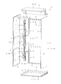
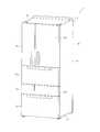
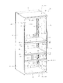
- Perspective view showing appearance of refrigerator The perspective view which shows the inside of the refrigerator seen from the front right
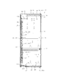
- Vertical side view of heat insulation box Cross-sectional plan view schematically showing the refrigerator compartment inside the heat insulation box
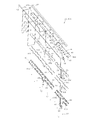
- Exploded perspective view of split insulation wall Transverse plan view schematically showing the right part of the front side of the heat insulation box
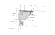
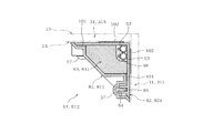
- Cross-sectional plan view schematically showing the left corner of the heat insulation box The perspective view which shows the attachment state of the fixing tool provided in the corner part of the left back side of a heat insulation box.
- Transverse plan view showing the mounting state of the fixture provided at the corner on the left back side of the heat insulation box (part 1)
- Transverse plan view (part 2) showing the mounting state of the fixture provided at the left back corner of the heat insulation box
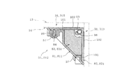
- Cross-sectional plan view schematically showing the corner on the right back side of the heat insulation box
- the perspective view which shows the attachment state of the fixing tool provided in the corner part of the right back side of a heat insulation box.
- the perspective view which shows the state before a fixture is attached to the corner part of the right back side of a heat insulation box.
- FIG. 9 equivalent view showing the fixture of the second embodiment.
- FIG. 22 equivalent view showing the heat insulating member of the third embodiment.
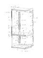
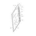
- the refrigerator 11 includes a heat insulating box 12 shown in FIG. 2 and a refrigeration cycle (not shown) for cooling the heat insulating box 12.
- the heat insulating box 12 is formed in a box shape with one surface opened.
- the opening side of the heat insulation box 12 be the front side of the refrigerator 11, and let the left-right direction of the paper surface of FIG.
- the heat insulating box 12 is configured as a box having an outer box 13, an inner box 14, and a heat insulating member 15 by combining a plurality of divided heat insulating walls 31.
- the heat insulating member 15 is provided between the outer box 13 and the inner box 14.
- Inside the inner box 14, for example, a storage space such as a storage room, a space where a duct is provided if necessary, and the like are formed.
- the outer box 13 is made of steel, for example, and is configured in a box shape with an open front surface.
- the outer box 13 constitutes the outer surface of the heat insulating box 12.
- the outer box 13 is configured by combining a plurality of divided outer plates.
- the outer box 13 includes an upper outer plate 16, a bottom outer plate 17, a right outer plate 18, a left outer plate 19, and a back outer plate 20.
- the upper outer plate 16 constitutes the upper outer surface of the heat insulating box 12.
- the upper outer plate 16 is formed in a step shape in which the rear portion is positioned below the front portion.
- the bottom outer plate 17 forms the bottom outer surface of the heat insulating box 12 and is formed in a substantially flat plate shape parallel to the upper outer plate 16.
- the right outer plate 18 and the left outer plate 19 are formed in a substantially flat plate shape and constitute the left and right outer surfaces of the heat insulating box 12.
- the right outer plate 18 and the left outer plate 19 are configured symmetrically.
- the back outer plate 20 is formed in a substantially flat plate shape and is provided on the back portion of the heat insulating box 12.
- the back outer plate 20 constitutes the back outer surface of the heat insulating box 12.
- a machine room 21 is formed on the upper rear portion of the upper outer plate 16.
- the machine room 21 is provided with a compressor constituting a refrigeration cycle (not shown).
- an upper separating portion 211 is formed at a position corresponding to the bottom surface of the machine room 21.
- the upper separating portion 211 is an opening formed by providing a gap between adjacent heat insulating members 15.
- the upper insulating portion 211 is formed by disposing the heat insulating member 15 located on the upper side of the heat insulating box 12 and the heat insulating member 15 located on the back side away from each other.
- a parts accommodating chamber 212 is formed on the lower rear side of the heat insulating box 12.
- the component storage chamber 212 stores, for example, a condenser for a refrigeration cycle, components used for refrigeration and freezing control, and the like.
- a lower spacing portion 213 is formed at a position corresponding to the component storage chamber 212.
- the lower side separation portion 213 is formed by arranging the heat insulation member 15 located on the bottom side of the heat insulation box 12 and the heat insulation member 15 located on the back side apart from each other.
- the inner box 14 is made of resin and is formed in a box shape with an opening on the front side.
- the inner box 14 is provided inside the outer box 13 and constitutes the inner surface of the heat insulating box 12.
- the inner box 14 is configured by combining a plurality of divided inner plates.
- the inner box 14 includes an upper inner plate 22, a bottom inner plate 23, a right inner plate 24, a left inner plate 25, and a back inner plate 26.
- the upper inner plate 22 constitutes the upper inner surface of the heat insulating box 12. Similar to the upper outer plate 16, the upper inner plate 22 is formed in a step shape in which the rear portion is positioned below the front portion.
- the bottom inner plate 23 constitutes the bottom inner surface of the heat insulating box 12 and is formed as a substantially flat plate parallel to the upper inner plate 22.
- the right inner plate 24 and the left inner plate 25 are formed in a substantially flat plate shape and constitute the left and right inner surfaces of the heat insulating box 12. In this case, the right inner plate 24 and the left inner plate 25 are configured symmetrically.
- the back inner plate 26 is formed in a substantially flat plate shape and is provided on the back portion of the heat insulating box 12. The back inner plate 26 constitutes the back inner surface of the heat insulating box 12.
- the right inner plate 24, the left inner plate 25, and the back inner plate 26 are provided with a plurality of support members 27, respectively.
- the plurality of support members 27 are on the right inner plate 24, the left inner plate 25, and the back inner plate 26, and are arranged in the vertical direction.
- the support member 27 is made of, for example, a resin, and as shown in FIGS. 20 and 21, is mainly composed of a rectangular parallelepiped block.
- the support member 27 has a screw hole 271 and a flange portion 272.
- the support member 27 is passed through an opening 28 formed in the inner plates 24, 25, and 26 and protrudes toward the storage chamber.
- the screw hole 271 is formed from the storage chamber side toward the inner plates 24, 25 and 26.
- a female screw is formed inside the screw hole 271.
- the flange portion 272 is formed in a plate shape larger than the main body of the support member 27, and is provided on the side opposite to the storage chamber with respect to the inner plates 24, 25, and 26.
- the flange portion 272 serving as a base end portion of the support member 27 is fixed by being bonded to the heat insulating member 15 and is sandwiched and fixed between the heat insulating member 15 and the inner plates 24, 25, and 26.
- the collar portion 272 functions as a retaining member that suppresses the support member 27 from falling off from the opening 28 toward the storage chamber.
- the support member 27 may be configured integrally with the inner plates 24, 25, and 26. Further, the support member 27 may have a configuration in which the base end portion of the support member 27 is bonded to the heat insulating member 15 without having the flange portion 272.
- the upper outer plate 16 and the upper inner plate 22, the bottom outer plate 17 and the bottom inner plate 23, the right outer plate 18 and the right inner plate 24, the left outer plate 19 and the left inner plate. 25, and the back outer plate 20 and the back inner plate 26 are opposed to each other via the heat insulating member 15. That is, a heat insulating member 15 is provided between the outer box 13 and the inner box 14 corresponding to each wall surface.
- the heat insulating member 15 is composed of a member having a low thermal conductivity and excellent heat insulating performance, such as a flat vacuum heat insulating panel, than a foam heat insulating material such as urethane or soft tape. Although the details are not shown, the heat insulating member 15 includes a core material and an outer bag body that accommodates the core material.
- the core material is formed by compressing and curing a highly heat-insulating material, for example, a laminate of inorganic fibers such as glass wool in a synthetic resin film inner bag such as polyethylene, and then compressing and curing it into a rectangular plate shape.
- the core material may be formed by, for example, a paper making method or a heat compression method.
- the outer bag body is formed in a bag shape by a film in which, for example, a polyethylene terephthalate film, a high density polyethylene film, an aluminum vapor deposition film, an aluminum foil sheet, and the like are appropriately combined and laminated.
- This outer bag body has a gas barrier property.
- the heat insulating member 15 is configured by reducing the pressure inside the outer bag while the core material is housed in the outer bag, and sealing the opening of the outer bag by heat welding or the like while maintaining the reduced pressure.
- the heat insulating member 15 has one surface bonded to the inner box 14, that is, the outer surface of the outer plate, and the other surface bonded to the outer box 13, that is, the inner surface of the inner plate.
- the heat insulating members 15 provided inside the walls constituting the heat insulating box 12 are in contact with the outer plates 16 to 20 and the inner plates 22 to 26, respectively.
- the heat insulating member 15 is sandwiched between the left outer plate 19 and the left inner plate 25 facing the left outer plate 19.
- the heat insulating member 15 and the left outer plate 19 are bonded by an adhesive 29.
- the heat insulating member 15 and the left inner plate 25 are bonded by an adhesive 30.
- the adhesives 29 and 30 are, for example, liquid adhesives or double-sided tapes.
- the support member 27 is bonded to the heat insulating member 15 with an adhesive 30.
- the plurality of divided heat insulating walls 31 include the outer plates 16 to 20, the inner plates 22 to 26 facing the outer plates 16 to 20, and the outer plates 16 to 20 and the inner plates 22 to 26.
- the member 15 is comprised.
- the heat insulation box 12 is comprised by combining this some division
- the divided heat insulating wall 31 may be referred to as a divided heat insulating panel.
- the divided heat insulating wall 31 includes five divided heat insulating walls 31 including an upper divided heat insulating wall 311, a bottom divided heat insulating wall 312, a right divided heat insulating wall 313, a left divided heat insulating wall 314, and a back divided heat insulating wall 315. Yes.
- the upper divided heat insulating wall 311 constitutes the upper wall of the heat insulating box 12
- the bottom divided heat insulating wall 312 constitutes the bottom wall of the heat insulating box 12
- the right divided heat insulating wall 313 is the right side of the heat insulating box 12.
- the left divided heat insulating wall 314 forms the left wall of the heat insulating box 12
- the back divided heat insulating wall 315 forms the back wall of the heat insulating box 12.
- the right divided heat insulating wall 313 and the left divided heat insulating wall 314 have a symmetrical shape and are arranged to face each other.
- the front end portions of the right divided heat insulating wall 313 and the left divided heat insulating wall 314 that form the left and right walls of the heat insulating box 12 will be described with reference to FIGS. 3, 4, and 8.
- the right divided heat insulating wall 313 and the left divided heat insulating wall 314 are configured symmetrically. For this reason, the description of the left divided heat insulating wall 314 is omitted by the description of the right divided heat insulating wall 313.
- the right divided heat insulating wall 313 has bent portions 32 at two locations near the front end and in the vicinity of the center in the vertical direction.
- the two bending parts 32 are the same structures, the bending part 32 provided in the center part of the up-down direction of the front-end part of the right side division
- segmentation heat insulation wall 313 is demonstrated.
- the bent portion 32 bends to the left at the front end portion of the right outer plate 18, and then folded to the right outer side of the outer case 13 in front of the right inner plate 24 of the inner case 14. It is formed into a shape.
- the bent portion 32 has two flat portions 321 extending in the left-right direction and a curved portion 322 connecting the two flat portions 321.
- the two flat portions 321 are substantially opposed to each other and are positioned in front of the heat insulating member 15.
- the curved portion 322 is bent by approximately 180 ° so as to be folded back, and is formed in a U-shape that is open to the right outside of the outer box 13 when viewed from above.
- the curved portion 322 is provided in front of the right inner plate 24 and at a position that substantially overlaps the right inner plate 24 in the left-right direction. In this case, the front end portion of the flat portion 321 is bent so as not to be located outside the heat insulating box 12.
- An opening 33 is formed between the curved portion 322 and the front end portion of the right inner plate 24. Further, an end insertion chamber 34 is formed between the bent portion 32 and the front end portion of the heat insulating member 15.
- the opening 33 is formed by separating the front end portion of the right inner plate 24 and the bent portion 32 of the right outer plate 18 and functions as an inlet of the end insertion chamber 34.
- the end insertion chamber 34 is a space formed by separating the bent portion 32 of the right outer plate 18 and the heat insulating member 15. Further, the two flat portions 321 are formed with through holes 35 penetrating in the plate thickness direction.
- the heat insulation box 12 has a first partition member 37 and a second partition member 38 inside the inner box 14.
- the first partition member 37 is provided at the center portion in the vertical direction inside the inner box 14.
- the second partition member 38 is provided below the first partition member 37.
- the first partition member 37 and the second partition member 38 partition the inner box 14 in the vertical direction. Thereby, the storage chamber formed inside the inner box 14 is divided into a plurality of chambers to form a plurality of chambers.
- the refrigerator 11 includes a refrigerator room 39, a vegetable room 40, an ice making room 41, a first freezing room 42, and a second freezing room 43 as storage rooms.
- the refrigerator compartment 39 is provided in a space surrounded by the inner box 14 and the first partition member 37.
- the vegetable compartment 40 is provided in a space surrounded by the inner box 14, the first partition member 37, and the second partition member 38.
- the ice making chamber 41, the first freezing chamber 42, and the second freezing chamber 43 are provided in a space below the inner box 14 surrounded by the inner box 14 and the second partition member 38.
- the ice making chamber 41 is provided on the lower left side of the second partition member 38
- the second freezing chamber 43 is provided on the right side of the ice making chamber 41.
- the first freezing chamber 42 is provided below the ice making chamber 41 and the second freezing chamber 43.
- the refrigerator 11 includes a refrigerator compartment door 391, a vegetable compartment door 401, an ice making compartment door 411, a first freezer compartment door 421, and a second freezer compartment door 431, as shown in FIG.
- the refrigerator compartment door 391 is a rotary type and is provided at the front opening of the refrigerator compartment 39.
- the vegetable compartment door 401 is a drawer type and is provided at the front opening of the vegetable compartment 40.
- the ice making room door 411, the first freezing room door 421, and the second freezing room door 431 are of a drawer type, and are front openings of the ice making room 41, the first freezing room 42, and the second freezing room 43, respectively.
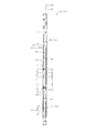
- first partition member 37 and the second partition member 38 will be described. Since the first partition member 37 and the second partition member 38 have substantially the same configuration in appearance, the first partition member 37 will be described as a representative with reference to FIG. Moreover, since the 1st partition member 37 is a left-right symmetric shape, the structure of the right side is demonstrated.
- the first partition member 37 includes a front partition portion 44 and a surface partition portion 45.
- the front partition 44 is provided on the opening side of the front surface of the heat insulating box 12 and is configured in a rectangular parallelepiped shape extending in the left-right direction.
- the front partition 44 includes a partition plate 441, a partition reinforcing plate 442, a partition cover 443, and a partition heat insulating member 444.
- the partition plate 441 is a metal plate member and constitutes a front wall of the front partition portion 44. The left and right ends of the partition plate 441 are bent slightly rearward.
- the left and right end portions of the partition plate 441 are inserted into the end insertion chamber 34 through the openings 33 formed at the front end portions of the left and right divided heat insulating walls 313 and 314, respectively.
- Three through holes 445 are formed at the right end of the front partition 44.
- the partition reinforcement plate 442 is a metal plate and is formed in a plate shape along the rear surface of the partition plate 441.
- the partition reinforcing plate 442 is set such that the vertical dimension is equal to or shorter than the vertical dimension of the partition plate 441. Further, the partition reinforcing plate 442 is set so that the dimension in the left-right direction is longer than the dimension in the left-right direction of the partition plate 441.
- the partition reinforcing plate 442 has a thickness equal to or thicker than that of the partition plate 441.
- the partition reinforcement plate 442 is provided in contact with the rear surface of the partition plate 441, that is, the back surface, with both left and right ends bent to the rear side. The partition reinforcing plate 442 is provided when the partition plate 441 has a low tensile strength.
- the right end portion of the partition plate 441 is sandwiched between the right end portion of the partition reinforcing plate 442 and the bent portion 32 of the right outer plate 18 in the end insertion chamber 34 of the right divided heat insulating wall 313. The same applies to the left end portion of the partition plate 441.
- the front surface of the partition plate 441 is flush with the front surface of the bent portion 32.
- the right end portion of the partition reinforcing plate 442 is bent in an L-shaped cross section at a position on the right side of the partition plate 441. That is, the right end portion of the partition plate 441 is bent rearward along the corner shape of the right front portion of the right outer plate 18. The same applies to the left end portion of the partition plate 441.
- the partition reinforcing plate 442 has three screw holes 446 at the right end. A female screw is formed inside the screw hole 446. The three screw holes 446 correspond to the respective through holes 445 formed in the partition plate 441. A screw 46 is provided in the screw hole 446 located on the rightmost side among the three locations. The screw 46 is passed through the through hole 35 of the right outer plate 18 and the through hole 445 of the partition plate 441.
- Screws 47 are provided in the remaining two screw holes 446 of the partition reinforcing plate 442.
- the screw 47 is passed through the through hole 445 of the partition plate 441. Accordingly, the right end portion of the partition plate 441 and the right end portion of the partition reinforcing plate 442 are connected and fixed to the bent portion 32 of the right outer plate 18.
- the left end portion of the partition plate 441 and the left end portion of the partition reinforcing plate 442 are configured in the same manner as the right end portion described above. That is, the left end portion of the partition plate 441 and the left end portion of the partition reinforcing plate 442 are connected and fixed to the left divided heat insulating wall 314, that is, the bent portion (not shown) of the left outer plate 19.
- the partition plate 441 functions as a connecting member that connects and fixes the right divided heat insulating wall 313 and the left divided heat insulating wall 314 on the opening side of the front surface of the heat insulating box 12.
- the bent portion 32 functions as a connected member.
- the partition cover 443 is made of metal and is formed in a horizontally long box shape with an opening on the front side.
- the partition cover 443 constitutes a rectangular parallelepiped outer wall of the front partition portion 44 together with the partition plate 441.
- the partition cover 443 is supported by the support member 27.
- the partition cover 443 has a mounting portion (not shown) at the lower portion, and the mounting portion is fixed to the support member 27 by screws (not shown).
- a partition heat insulating member 444 is provided in a rectangular parallelepiped space formed by the partition cover 443 and the partition plate 441.
- the partition heat insulation member 444 is comprised by heat insulation members, such as a polystyrene foam and urethane, and is formed in the rectangular parallelepiped shape.
- the surface partition portion 45 is formed in a rectangular plate shape as a whole by a resin member.
- the surface partition portion 45 of the second partition member 38 has a heat insulating member such as a vacuum heat insulating panel inside.
- the surface partition part 45 of the 2nd partition member 38 has heat insulation.
- the surface partition 45 is placed and held on the support member 27. Further, the front partitioning portion 45 is in contact with the back surface of the front partitioning portion 44, and both left and right end portions are in contact with the right inner plate 24 and the left inner plate 25.
- the first partition member 37 has a gap between the rear end portion of the surface partition portion 45 and the back inner plate 26. Thereby, the refrigerator compartment 39 and the vegetable compartment 40 are connected.
- the rear-end part of the surface partition part 45 and the back part inner board 26 are contacting. Thereby, the refrigerator compartment 39 and the vegetable compartment 40 are insulated from the ice making room 41, the first freezing room 42, and the second freezing room 43.
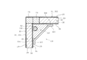
- the divided heat insulating wall 31 is connected and fixed to another adjacent heat insulating wall 31 via a fixture 51.
- the fixture 51 is in the inner box 14 and is formed with a corner portion formed by the upper inner plate 22 and the right inner plate 24, a corner portion formed by the upper inner plate 22 and the left inner plate 25, and an upper portion.
- the fixture 51 is fixed at a position facing the two heat insulating members 15 that are adjacent to each other and spaced apart.
- an electric wire 52 is arranged at one corner portion at the rear of the inner box 14, for example, the corner portion on the back left side formed by the left inner plate 25 and the back inner plate 26. ing.
- the electric wire 52 extends along the corner portion.
- the electric wire 52 is a power supply and signal electric wire for connecting the blower fan, various sensors, and the control device.
- the electric wire 52 is arranged by bundling a plurality of electric wires.
- the drawing shows an electric wire 52 in which a plurality of electric wires are bundled to have a circular cross section.
- a pipe 53 is arranged.
- the pipe 53 extends along the corner portion.
- the pipe 53 is a suction pipe or the like that connects an evaporator (not shown) for refrigeration and freezing and a compressor.
- two pipes 53 are provided side by side, a refrigerant used for refrigeration flows through one pipe 53, and a refrigerant used for freezing flows through the other pipe 53.
- the fixtures 51 provided at each corner portion of the inner box 14 have a similar configuration, hereinafter, the fixtures 511 provided at the corner portion formed by the left inner plate 25 and the back inner plate 26.
- the fixing tool 512 provided in the corner portion formed by the right inner plate 24 and the back inner plate 26 will be described. In the description of the fixture 512, the description of the parts common to the fixture 511 is omitted.
- the fixture 511 will be described with reference to FIGS. 1 and 9 to 21.
- the fixture 511 has a column shape that is long in the vertical direction as a whole, and has a horizontal section, that is, a cross section in the lateral direction, formed in a right triangle shape.
- the fixture 511 extends in the vertical direction along a corner portion formed by the left inner plate 25 and the back inner plate 26.
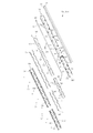
- the fixture 511 includes a fixed cover 54, a reinforcing member 55, and a corner heat insulating member 56.
- the fixing tool 511 is formed in a cylindrical shape having a right-angled triangular cross section by the fixing cover 54 and the reinforcing member 55.
- the corner heat insulating member 56 is disposed inside a cylindrical shape formed by the fixed cover 54 and the reinforcing member 55.
- the fixed cover 54 is formed in a substantially rectangular plate shape that is long in the vertical direction by a resin member.
- the fixed cover 54 forms an inclined surface among the three surfaces forming the right triangle cross section of the fixture 511.
- the fixed cover 54 has a plurality of through holes 58 and openings 59 and 60.
- the through holes 58 are provided at both ends in the width direction orthogonal to the longitudinal direction of the fixed cover 54.
- the through holes 58 at both ends are formed by penetrating the fixed cover 54 toward the left divided heat insulating wall 314 or the back divided heat insulating wall 315.
- the through hole 58 is arranged so as to be as far away as possible from the through hole 58 at the other end. That is, the through hole 58 is arranged so as to be shifted from the through hole 58 positioned at the other end so that the vertical direction is alternate. In this case, as shown in FIG. 13, for example, the through holes 58 are arranged in a so-called zigzag shape along the longitudinal direction of the fixed cover 54.
- a screw 57 is passed through the through hole 58.
- the insertion direction of the screw 57 with respect to the through hole 58 on the left divided heat insulating wall 314 side is orthogonal to the inner side surface of the left divided heat insulating wall 314, that is, the surface of the left inner plate 25.
- the insertion direction of the screw 27 with respect to the through hole 58 on the back-side divided heat insulating wall 315 side is orthogonal to the inner side surface of the back-side divided heat insulating wall 315, that is, the surface of the back inner plate 26 as shown in FIG.
- the opening 59 is provided in the longitudinal direction of the fixed cover 54, that is, closer to the upper part in the vertical direction.
- the opening 60 is provided closer to the lower portion of the fixed cover 54 in the vertical direction.
- the openings 59 and 60 communicate with the cylindrical inner side of the fixture 511.
- the reinforcing member 55 is made of a resin member. As shown in FIG. 14, the reinforcing member 55 has a so-called L-shaped cross section in which the longitudinal sides of two rectangular plates that are long in the vertical direction are abutted at right angles to each other. The reinforcing member 55 constitutes two surfaces other than the slope among the three surfaces constituting the right triangle cross section of the fixture 511. The reinforcing member 55 reinforces the fixed cover 54 and improves the strength of the fixture 511.
- the reinforcing member 55 has a length in the longitudinal direction substantially the same as a length in the longitudinal direction of the fixed cover 54.
- the reinforcing member 55 is arranged such that one surface faces the left inner plate 25, that is, the left divided heat insulating wall 314, and the other surface faces the back inner plate 26, that is, the back divided heat insulating wall 315.
- the reinforcement member 55 is arrange
- the heat insulating member 15 is not provided in the corner portion where the adjacent divided heat insulating walls 31 are abutted, the heat insulating performance is lower than the other portions of the divided heat insulating walls 31.
- the fixture 511 is disposed in a portion where the heat insulating performance of the divided heat insulating wall 31 is low.
- the reinforcing member 55 has a plurality of screw holes 61 and a plurality of through holes 62 as shown in FIGS. 14, 16 and 17.
- the screw hole 61 and the through hole 62 are provided at both ends in the width direction orthogonal to the longitudinal direction of the reinforcing member 55.
- the screw hole 61 and the through hole 62 correspond to the through hole 58 of the fixed cover 54 and are arranged in a so-called zigzag shape along the longitudinal direction of the reinforcing member 55.
- the screw hole 61 is configured to have a female screw inside the cylinder that protrudes toward the fixed cover 54 in the reinforcing member 55.
- the axial direction of the screw hole 61 coincides with the axial direction of the through hole 58 of the fixed cover 54 in a form in which the fixed cover 54 is attached to the reinforcing member 55.
- a screw 57 is provided in the screw hole 61.
- the through-hole 62 is formed by penetrating the bulging portion 63 provided in the reinforcing member 55 toward the left inner plate 25 or the back inner plate 26 side.
- the bulging portion 63 is formed such that both end portions in the short direction of the reinforcing member 55 bulge toward the fixed cover 54 side.
- the bulging portion 63 is also arranged in a so-called zigzag shape along the longitudinal direction of the reinforcing member 55.
- a screw 57 is passed through the through hole 62.
- the corner heat insulating member 56 is disposed so as to cover the butted portions of the adjacent divided heat insulating walls 31.
- the corner heat insulating member 56 is formed of a heat insulating member such as polystyrene foam formed in a substantially triangular prism that is long in the vertical direction.
- the corner heat insulating member 56 includes a plurality of notches 64, two openings 65 and 66, and a housing 67.
- the notch 64 is formed by cutting out both ends in the width direction orthogonal to the longitudinal direction of the corner heat insulating member 56 into a rectangle.
- the notch portion 64 is a so-called zigzag along the longitudinal direction of the corner heat insulating member 56 so as not to interfere with the through hole 58 of the fixed cover 54, the screw hole 61 of the reinforcing member 55, and the screw 57 provided in the through hole 62. Arranged in a shape.
- the openings 65 and 66 are formed by cutting out both ends in the width direction perpendicular to the longitudinal direction of the corner heat insulating member 56 into a rectangle.
- the opening 65 corresponds to the opening 59 of the fixed cover 54
- the opening 66 corresponds to the opening 60 of the fixed cover 54.
- the accommodating portion 67 is formed in a groove shape extending in the longitudinal direction in a right-angle portion in a cross section orthogonal to the longitudinal direction of the corner heat insulating member 56, that is, in a portion close to the corner of the corner portion of the inner box 14.
- the electric wire 52 is accommodated inside the accommodating portion 67. That is, the fixture 511 accommodates the electric wire 52 in a cylindrical shape.
- the electric wire 52 is held so as not to be displaced from a predetermined position by the inner surface of the housing portion 67 serving as a holding portion.
- the electric wire 52 is also held by a hook or the like (not shown). In this case, a portion of the electric wire 52 that is provided inside the cylindrical shape of the fixture 511 is not visible from the opening side of the refrigerator 11.
- the fixture 511 is configured by connecting a part that is divided in two at the height position of the second partition member 38 in the longitudinal direction, that is, the vertical direction, in this case, an upper fixture 511 and a lower fixture 511 are connected. ing. Therefore, as shown in FIGS. 1, 12, 13, and 14, the fixed cover 54 has two parts divided in the longitudinal direction of the fixed cover 54, in this case, the upper fixed cover 541 and the lower fixed cover 542. It is composed of With this configuration, the fixed cover 54 can be easily handled, and deformation such as twisting is less likely to occur. In this case, the opening 59 is provided in the upper fixed cover 541, and the opening 60 is provided in the lower fixed cover 542.
- the reinforcing member 55 includes two parts divided in the longitudinal direction of the reinforcing member 55, in this case, an upper reinforcing member 551 and a lower reinforcing member 552.
- the corner heat insulating member 56 is also composed of two parts divided in the longitudinal direction of the corner heat insulating member 56, in this case, an upper corner heat insulating member 561 and a lower corner heat insulating member 562.
- the opening 65 is provided in the upper corner heat insulating member 561, and the opening 66 is provided in the lower corner heat insulating member 562.
- the upper fixing cover 541, the upper reinforcing member 551, and the upper corner heat insulating member 561 constitute an upper fixing member 511.
- the lower fixing cover 542, the lower reinforcing member 552, and the lower corner heat insulating member 562 constitute a lower fixing tool 511.
- the upper fixture 511 is arranged on the refrigerator compartment 39 and vegetable compartment 40 side
- the lower fixture 512 is arranged on the ice making chamber 41 and first freezer compartment 42 side. ing.
- Two screw holes 48 are provided at the lower end of the upper reinforcing member 551. Then, two through holes 49 are provided at positions corresponding to the screw holes 48 at the upper end of the lower reinforcing member 552. The upper reinforcing member 551 and the lower reinforcing member 552 are fixed by screwing the screw 50 passed through the through hole 49 into the screw hole 48.
- the fixture 511 as a whole is configured to be split into two in the direction extending along the corner portion, that is, in the longitudinal direction.
- the lower end portion of the upper corner heat insulating member 561 is in contact with the upper end portion of the lower corner heat insulating member 562.
- the lower end portion of the upper fixed cover 541 is separated from the upper end portion of the lower fixed cover 542.
- the electric wire 52 extends from the machine room 21 through the upper separating portion 211 to the refrigerator compartment 39 side, and enters the accommodating portion 67 of the corner heat insulating member 56 from the upper end portion of the fixture 511.
- the electric wire 52 branches in two directions within the housing portion 67.
- One of the electric wires 52 passes through the opening 65 of the upper corner heat insulating member 561 and extends from the opening 59 of the upper fixing cover 541 to the refrigerator compartment 39 side.
- the other of the electric wires 52 passes through the opening 66 of the lower corner heat insulating member 562 and extends from the opening 60 of the lower fixing cover 542 to the first freezer compartment 42 side.
- the openings 59 and 60 are for guiding a part of the electric wire 52 accommodated in the fixture 511 to the storage chamber side.
- a part of the electric wire 52 may be guided from the lower end surface of the fixture 511 to the component housing chamber 212 through the lower spacing portion 213.
- the electric wire 52 has the connection part 68 in each edge part, as shown in FIG.13 and FIG.14. These connection portions 68 are made of resin and are configured in a plug shape.
- the connecting portion 68 is connected to an electric wire (not shown) outside the fixture 511, and is connected to an electrical component such as a control device or a blower fan via the electric wire.
- the first seal member 71 is a sheet-like member that extends long along the longitudinal direction of the fixed cover 54 and the reinforcing member 55, and is made of, for example, a soft tape.
- the first seal member 71 seals between the fixed cover 54 and the reinforcing member 55. That is, the first seal member 71 increases the airtightness between the fixed cover 54 and the reinforcing member 55.
- a second seal member 72 is provided between the reinforcing member 55 and the left divided heat insulating wall 314 and between the reinforcing member 55 and the back divided heat insulating wall 315.
- the second seal member 72 is a sheet-like member extending long along the longitudinal direction of the fixed cover 54 and the reinforcing member 55, and is made of, for example, a soft tape.
- the second seal member 72 seals between the reinforcing member 55 and the left divided heat insulating wall 314 and between the reinforcing member 55 and the back divided heat insulating wall 315. That is, the second seal member 72 enhances the airtightness between the reinforcing member 55 and the left inner plate 25 and between the reinforcing member 55 and the back inner plate 26.
- a third seal member 73 is provided at an end of the divided heat insulating wall 31, for example, a portion where the left divided heat insulating wall 314 and the back divided heat insulating wall 315 are abutted.
- the third seal member 73 is a quadrangular columnar member extending in parallel with the longitudinal direction of the fixed cover 54 and the reinforcing member 55, and is made of, for example, a soft tape.
- the third seal member 73 assists heat insulation in the space formed at the abutting portion between the left divided heat insulating wall 314 and the back divided heat insulating wall 315, and suppresses the entry of air containing moisture into the space.
- the illustration of the third seal member is omitted.
- the fixture 511 is configured such that the fixing cover 54 and the reinforcing member 55 sandwich the corner heat insulating member 56.
- the corner heat insulating member 56 accommodates the electric wire 52 in the accommodating portion 67.
- a screw 57 is passed through the through hole 58 in a state where the end in the width direction is aligned with the end in the width direction of the reinforcing member 55.
- the screw 57 passed through the through hole 58 is screwed into the screw hole 61 of the reinforcing member 55.
- the fixed cover 54 is fixed to the reinforcing member 55.
- the fixing cover 54 is fixed to the reinforcing member 55, whereby the corner heat insulating member 56 and the electric wire 52 are also fixed inside the fixture 511.
- the fixed cover 54, the reinforcing member 55, the corner heat insulating member 56, and the electric wire 52 are integrated.
- the left rear end portion of the second partition member 38 enters between the upper fixed cover 541 and the lower fixed cover 542 and comes into contact with a connection portion between the upper corner heat insulating member 561 and the lower corner heat insulating member 562. Yes.
- the divided portion of the fixture 511 is covered with the left rear end portion of the second partition member 38.
- the left divided heat insulating wall 314 and the back divided heat insulating wall 315 are opposed to the reinforcing member 55 through the second seal member 72.
- the adjacent left side heat insulation wall 314 and the back side heat insulation wall 315 are connected and fixed by the fixture 511, and the angle formed by the left side heat insulation wall 314 and the back side heat insulation wall 315 is reinforced. It is held at 90 ° corresponding to the right angle portion of the member 55. That is, the reinforcing member 55 functions as an angle holding portion that holds the angle between the adjacent left side divided heat insulating wall 314 and the back side divided heat insulating wall 315 at 90 °.
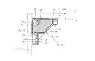
- the fixture 512 has a column shape that is long in the vertical direction as a whole, and has a horizontal section, that is, a cross section in the short direction, formed into a right triangle. As shown in FIG. 23, the fixture 512 extends in the vertical direction along a corner portion formed by the right inner plate 24 and the back inner plate 26.
- the fixing tool 512 includes a fixing cover 81, a reinforcing member 82, and a corner heat insulating member 83, as shown in FIGS.
- the fixing member 512 is formed in a cylindrical shape having a right-angled triangular cross section by the fixing cover 81 and the reinforcing member 82.
- the corner heat insulating member 83 is disposed inside the cylindrical shape formed by the fixed cover 81 and the reinforcing member 82.
- the fixed cover 81 is configured in substantially the same manner as the fixed cover 54. Specifically, the fixed cover 81 is formed in a substantially rectangular plate shape that is long in the vertical direction by a resin member. The fixed cover 81 forms an inclined surface among the three surfaces forming the right triangle cross section of the fixture 512. As shown in FIG. 27, the fixed cover 81 has a plurality of through holes 84.
- the through hole 84 is configured similarly to the through hole 58 of the fixed cover 54. That is, the through holes 84 are provided at both ends in the width direction orthogonal to the longitudinal direction of the fixed cover 81.
- the through holes 84 at both ends are formed through the fixed cover 81 toward the right divided heat insulating wall 313 or the back divided heat insulating wall 315, respectively.
- the through-hole 84 is arranged so as to be shifted from the through-hole 84 positioned at the other end so that the vertical direction is staggered.
- the through holes 84 are arranged in a so-called zigzag shape along the longitudinal direction of the fixed cover 81 as shown in FIG. 27, for example.
- a screw 57 is passed through the through hole 84.
- the insertion direction of the screw 27 with respect to the through hole 84 on the back side divided heat insulation wall 315 side is orthogonal to the inner side surface of the back side divided heat insulation wall 315, that is, the surface of the back inner plate 26, as shown in FIG.
- the insertion direction of the screw 27 with respect to the through hole 84 on the right divided heat insulating wall 313 side is orthogonal to the inner side surface of the right divided heat insulating wall 313, that is, the surface of the right inner plate 24, as shown in FIG.
- the fixed cover 81 has the 1st protrusion part 85, the opening part 86, the 2nd protrusion part 87, and the opening part 88, as shown to FIG.
- the first projecting portion 85 is located near the upper portion in the longitudinal direction of the fixed cover 81 and projects outward. That is, the first protrusion 85 extends in the horizontal direction from the surface of the fixed cover 81 along the back inner plate 26.
- the 1st protrusion part 85 is formed in the rectangular container shape which the back part inner board 26 side opened.
- the opening 86 is provided at the tip of the first protrusion 85 and communicates the inside and the outside of the first protrusion 85.
- the second protrusion 87 is provided near the lower part of the fixed cover 81 in the longitudinal direction. Similarly to the first protrusion 85, the second protrusion 87 protrudes outward. That is, the second projecting portion 87 extends in the horizontal direction along the back inner plate 26 from the surface of the fixed cover 81.
- the 2nd protrusion part 87 is also formed in the rectangular container shape which the back part inner board 26 side opened.
- the opening 88 is provided at the tip of the second protrusion 87 and communicates the inside and the outside of the second protrusion 87.
- the reinforcing member 82 is configured in substantially the same manner as the reinforcing member 55. That is, the reinforcing member 82 is configured by a resin member.
- the main part of the reinforcing member 82 is formed in a so-called L-shaped cross section in which the longitudinal sides of two rectangular plates that are long in the vertical direction are abutted at right angles to each other.
- the reinforcing member 82 constitutes two surfaces other than the slope among the surfaces constituting the cross section of the right triangle of the fixture 512.
- the reinforcing member 82 reinforces the fixed cover 81 and improves the strength of the fixture 512.
- the reinforcing member 55 has a length in the longitudinal direction substantially the same as a length in the longitudinal direction of the fixed cover 54.
- the reinforcing member 82 has a first reinforcing protrusion 91 and a second reinforcing protrusion 92.
- the first reinforcing protrusion 91 and the second reinforcing protrusion 92 are each plate-shaped and are provided at positions corresponding to the first protrusion 85 and the second protrusion 87 of the fixed cover 81.
- the first reinforcing protrusion 91 and the second reinforcing protrusion 92 are formed integrally with the main portion of the reinforcing member 82.
- the 1st protrusion part 85 and the 1st reinforcement protrusion part 91, and the 2nd protrusion part 87 and the 2nd reinforcement protrusion part 92 each form the cylinder shape.
- the reinforcing member 82 is disposed such that one surface faces the right inner plate 24, that is, the right divided heat insulating wall 313, and the other surface faces the back inner plate 26, that is, the back divided heat insulating wall 315.
- the reinforcement member 82 is arrange
- the heat insulating member 15 is not provided in the corner portion where the adjacent divided heat insulating walls 31 are abutted, the heat insulating performance is lower than the other portions of the divided heat insulating walls 31.
- the fixture 512 is disposed in a portion where the heat insulating performance of the divided heat insulating wall 31 is low.
- the reinforcing member 82 has a plurality of screw holes 89 and a plurality of through holes 90 as shown in FIG.
- the screw hole 89 and the through hole 90 are configured similarly to the screw hole 61 and the through hole 62 of the reinforcing member 55. That is, the screw hole 89 and the through hole 90 are provided at both ends in the width direction orthogonal to the longitudinal direction of the reinforcing member 82.
- the screw hole 89 and the through hole 90 correspond to the through hole 84 of the fixed cover 81 and are arranged in a so-called zigzag shape along the longitudinal direction of the reinforcing member 82.
- the screw hole 89 is configured to have a female screw inside the cylinder that protrudes toward the fixed cover 81 in the reinforcing member 82.
- the axial direction of the screw hole 89 coincides with the axial direction of the through hole 84 of the fixed cover 81 in the form in which the fixed cover 81 is attached to the reinforcing member 82.
- a screw 57 is provided in the screw hole 89.
- the through hole 90 is formed by penetrating the bulging portion 77 provided in the reinforcing member 82 toward the right inner plate 24 or the back inner plate 26 side.
- the bulging portion 77 is formed such that both ends of the reinforcing member 82 in the short direction bulge toward the fixed cover 81.
- the bulging portion 77 is also arranged in a so-called zigzag shape along the longitudinal direction of the reinforcing member 82.
- a screw 57 is passed through the through hole 90.
- the heat insulating member for corner 83 is configured in substantially the same manner as the heat insulating member for corner 56. That is, the corner heat insulating member 83 is also arranged so as to cover the abutting portion of the adjacent divided heat insulating walls 31. As shown in FIG. 27, the corner heat insulating member 83 is formed of a heat insulating member such as a polystyrene foam formed in a substantially triangular prism that is long in the vertical direction.
- the corner heat insulating member 83 includes a plurality of notches 93, a first heat insulating protrusion 94, an opening 95, a second heat insulating protrusion 96, an opening 97, and a housing part 98.
- the notch 93 is formed by cutting out both ends in the width direction orthogonal to the longitudinal direction of the corner heat insulating member 83 into a rectangle.
- the notch 93 is a so-called zigzag along the longitudinal direction of the corner heat insulating member 83 so as not to interfere with the through hole 84 of the fixed cover 81, the screw hole 89 of the reinforcing member 82, and the screw 57 provided in the through hole 90. Arranged in a shape.
- the accommodating part 98 is comprised similarly to the accommodating part 67 of the heat insulation member 56 for corners. That is, the accommodating portion 98 is formed in a groove shape extending in the longitudinal direction in a right-angle portion in a cross section orthogonal to the longitudinal direction of the corner heat insulating member 83, that is, in a portion close to the corner of the corner portion of the inner box 14. Yes.
- the first heat-insulating protrusion 94 is located near the top of the corner heat-insulating member 83, that is, at a position corresponding to the first protrusion 85, and protrudes outward. That is, the first heat insulating protrusion 94 extends in the horizontal direction along the back inner plate 26 from the main portion of the corner heat insulating member 83.
- the first heat-insulating protrusion 94 is formed in a quadrangular prism shape.
- the opening 95 is provided at the distal end portion of the first heat-insulating protrusion 94 and communicates with the inside of the accommodating portion 98.
- the first heat-insulating protrusion 94 is accommodated inside a cylindrical shape composed of the first protrusion 85 and the first reinforcing protrusion 91.
- the second heat insulating protrusion 96 is located near the lower portion of the corner heat insulating member 83, that is, at a position corresponding to the second protrusion 87, and protrudes outward. That is, the second heat insulating protrusion 96 extends in the horizontal direction along the back inner plate 26 from the main portion of the corner heat insulating member 83.
- the second heat insulating projection 96 is also formed in a quadrangular prism shape.
- the opening 97 is provided at the tip of the second heat insulating projection 96 and communicates with the inside of the housing 98.
- the second heat-insulating protrusion 96 is accommodated inside a cylindrical shape constituted by the second protrusion 87 and the second reinforcing protrusion 92.
- the piping 53 is accommodated inside the accommodating portion 98.
- the fixture 512 accommodates the pipe 53 inside a cylindrical shape.
- the piping 53 is held so as not to be displaced from a predetermined position by the inner side surface of the accommodating portion 98 serving as a holding portion.
- the pipe 53 is also held by a hook or the like (not shown). In this case, a portion of the pipe 53 provided on the cylindrical inner side of the fixture 512 is not visible from the opening side of the refrigerator 11.
- a plurality of pipes 53 are accommodated depending on the part of the corner portion.
- the fixture 512 is configured by connecting a part divided into two at the height position of the second partition member 38 in the longitudinal direction, that is, the vertical direction, in this case, an upper fixture 512 and a lower fixture 512 are connected.
- the fixed cover 81 includes two parts divided in the longitudinal direction of the fixed cover 81, in this case, an upper fixed cover 811 and a lower fixed cover 812. With this configuration, the fixed cover 81 can be easily handled, and deformation such as twisting is less likely to occur.
- the first protrusion 85 and the opening 86 are provided in the upper fixed cover 811
- the second protrusion 87 and the opening 88 are provided in the lower fixed cover 812.
- the reinforcing member 82 includes two parts divided in the longitudinal direction of the reinforcing member 82, in this case, an upper reinforcing member 821 and a lower reinforcing member 822.
- the corner heat insulating member 83 is also composed of two parts divided in the longitudinal direction of the corner heat insulating member 83, in this case, an upper corner heat insulating member 831 and a lower corner heat insulating member 832.
- the first heat insulating protrusion 94 and the opening 95 are provided in the upper corner heat insulating member 831, and the second heat insulating protrusion 96 and the opening 97 are provided in the lower corner heat insulating member 832.
- the upper fixing cover 811, the upper reinforcing member 821, and the upper corner heat insulating member 931 constitute an upper fixture 512.
- the lower fixing cover 812, the lower reinforcing member 822, and the lower corner heat insulating member 932 constitute a lower fixing tool 512.
- the upper fixture 512 is disposed on the refrigerator compartment 39 and vegetable compartment 40 side, and the lower fixture 512 is on the second freezer compartment 43 and first freezer compartment 42 side. Has been placed.
- Two screw holes 74 are provided at the lower end of the upper reinforcing member 821. Then, at the upper end portion of the lower reinforcing member 822, two through holes 75 are provided at positions corresponding to the screw holes 74. The upper reinforcing member 821 and the lower reinforcing member 822 are fixed by screwing the screw 76 passed through the through hole 75 into the screw hole 74.
- the fixture 512 is configured to be divided into two parts in the direction extending along the corner portion, that is, the longitudinal direction, as a whole.
- the lower end portion of the upper corner heat insulating member 831 is in contact with the upper end portion of the lower corner heat insulating member 832.
- the lower end portion of the upper fixed cover 811 is separated from the upper end portion of the lower fixed cover 812.
- the pipe 53 is composed of two bent pipes. Each pipe 53 has one end connected to a compressor provided in the machine room 21 and the other end connected to a cooler. Specifically, each pipe 53 extends from the machine room 21 side to the refrigerating room 39 side through the upper separation part 211 and enters the housing part 98 of the corner heat insulating member 83 from the upper end part of the fixture 512. . One of the two pipes 53 passes through the inside of the first heat insulating protrusion 94 provided in the upper corner heat insulating member 831 and passes from the opening 95 and the opening 86 to the refrigerator compartment 39 side. It extends. The pipes 53 coming out of the openings 95 and 86 are connected to a refrigerator for refrigeration, although details are not shown.
- the other pipe 53 passes through the inside of the second heat insulating protrusion 96 provided in the lower corner heat insulating member 832 and extends from the opening 97 and the opening 88 to the first freezer compartment 42 side.
- the pipes 53 exiting from the openings 97 and 88 are connected to a refrigeration cooler.
- the openings 86 and 88 are for guiding a part of the pipe 53 accommodated in the fixture 512 to the storage chamber side. A part of the pipe 53 may be guided from the lower end surface of the fixture 512 to the component housing chamber 212 through the lower spacing portion 213.
- Each pipe 53 has welded portions 99 at both ends as shown in FIGS.
- the welded portion 99 is formed so that the diameter of the pipe 53 is larger than that of other pipes, so that it can be welded to the welded parts of the other pipes.
- Each piping 53 is welded and connected to other piping outside the fixture 512.
- the other piping refers to piping connected to, for example, a refrigeration evaporator, a refrigeration evaporator, and a compressor.
- a first seal member 101 is provided between the fixed cover 81 and the reinforcing member 82, specifically, between the widthwise end of the fixed cover 81 and the widthwise end of the reinforcing member 82, as shown in FIGS.
- the first seal member 101 is configured in the same manner as the first seal member 71 provided on the fixture 511.
- a second seal member 102 is provided between the reinforcing member 82 and the right divided heat insulating wall 313 and between the reinforcing member 82 and the back divided heat insulating wall 315, as shown in FIGS. .
- the second seal member 102 is configured in the same manner as the second seal member 72 provided on the fixture 511 side.
- a third seal member 103 is provided at a portion where the right divided heat insulating wall 313 and the back divided heat insulating wall 315 are abutted.
- the third seal member 103 is configured in the same manner as the third seal member 73 provided at the abutting portion between the right divided heat insulating wall 313 and the back divided heat insulating wall 315.
- the fixture 512 is configured such that the fixing cover 81 and the reinforcing member 82 sandwich the corner heat insulating member 83.
- the corner heat insulating member 83 accommodates the pipe 53 in the accommodating portion 98.
- the screw 57 is passed through the through hole 84 in a state where the end in the width direction is aligned with the end in the width direction of the reinforcing member 82.
- the screw 57 passed through the through hole 84 is screwed into the screw hole 61 of the reinforcing member 82.
- the fixed cover 81 is fixed to the reinforcing member 82.
- the fixing cover 81 is fixed to the reinforcing member 82, whereby the corner heat insulating member 83 and the pipe 53 are also fixed inside the fixture 51.
- the fixed cover 81, the reinforcing member 82, the corner heat insulating member 83, and the pipe 53 are integrated.
- the right rear end portion of the second partition member 38 enters between the upper fixed cover 811 and the lower fixed cover 812 and comes into contact with the connection portion between the upper corner heat insulating member 831 and the lower corner heat insulating member 832. Yes.
- the divided portion of the fixture 512 is covered with the right rear end portion of the second partition member 38.
- the right divided heat insulating wall 313 and the back divided heat insulating wall 315 are opposed to the reinforcing member 82 with the second seal member 102 interposed therebetween.
- the adjacent right side heat insulation wall 313 and the back side heat insulation wall 315 are connected and fixed by the fixture 512, and the angle formed by the right side heat insulation wall 313 and the back side heat insulation wall 315 is reinforced.
- the member 82 is held at 90 ° corresponding to the right angle portion. That is, the reinforcing member 82 functions as an angle holding portion that holds the angle between the adjacent right divided heat insulating wall 313 and the back divided heat insulating wall 315 at 90 °.
- the pipe 53 may pass between the right end edge of the second partition member 38 and the right inner plate 24 as shown in FIG.
- a heat insulating member 105 for the partition portion is provided between the surface partition portion 45 of the second partition member 38 and the right inner plate 24 of the inner box 14 inside the inner box 14.
- the partition heat insulating member 105 is made of, for example, expanded polystyrene and functions as a heat insulating member.
- the partition heat insulating member 105 is formed in a rectangular column shape that is long in the front-rear direction along the right edge of the second partition member 38.
- the partition heat insulating member 105 has a recess 106.
- the concave portion 106 is formed in a concave shape in which the right inner plate 24 side of the partition heat insulating member 105 is opened.
- a part of the pipe 53 is provided inside the recessed portion 106 of the partition heat insulating member 105.
- the piping 53 may be arranged as follows.
- the two pipes 53 respectively enter the accommodating portion 98 of the upper corner heat insulating member 831 from the upper end portion of the fixture 512 and extend downward. Thereafter, the pipes 53 exit from the connecting portions of the upper corner heat insulating member 831 and the lower corner heat insulating member 832 to the outside front of the housing portion 98, respectively.
- the pipes 53 respectively pass through the inside of the recess 106 of the partition heat insulating member 105 and extend forward along the right end edge of the second partition member 38. Thereafter, the pipes 53 are folded back to the rear side at the front end portion of the second partition member 38 and extend rearward along the right end edge portion of the second partition member 38 again inside the recess 106.
- the pipes 53 enter the insides of the accommodating portions 98 of the lower corner heat insulating member 832 from the connection portions of the upper corner heat insulating member 831 and the lower corner heat insulating member 832, respectively. Thereafter, the pipe 53 exits from the openings 86 and 88 and is connected to the refrigeration cooler and the refrigeration cooler, respectively.
- a configuration similar to that of the partition heat insulating member 105 is also provided between the surface partition portion 45 of the second partition member 38 and the left inner plate 25 of the inner box 14.
- a member may be provided, and the electric wire 52 may be disposed along the left edge portion of the second partition member 38 in the same manner as the pipe 53 described above.
- segmentation heat insulation wall 31 and the fixing tool 51 which are shown in FIG. 1 are each manufactured.
- a fixing tool 511 is attached to one of the two adjacent divided heat insulation walls 31, for example, the left divided heat insulation wall 314 with a screw 57.
- the back divided heat insulating wall 315 is attached to the left divided heat insulating wall 314 and the fixture 511 integrated.
- the adjacent divided heat insulating walls 31, in this case, the left divided heat insulating wall 314 and the back divided heat insulating wall 315 are connected and fixed, and a corner portion on the right back side of the inner box 14 is formed.
- the angle between adjacent walls formed by the left divided heat insulating wall 314 and the back divided heat insulating wall 315 is maintained at 90 ° corresponding to the right angle portion of the reinforcing member 55.
- the other corner portion of the inner box 14 is also formed by connecting and fixing the divided heat insulating wall 31 and the fixture 51. Thereby, the inner box 14 whose angle of the adjacent division
- the fixture 51 defines the angle of the adjacent divided heat insulating walls 31 to a predetermined value, for example, 90 °.
- a predetermined value for example, 90 °.
- the angle of the adjacent divided heat insulating wall 31 is set to 90 °, but in this case, the angle of the adjacent divided heat insulating wall 31 is adjusted to approximately 90 °, and each corner portion of the heat insulating box 12 is approximately 90 °. It only has to be. That is, the angle defined by the fixture 51 does not need to be exact and is allowed within a range of general errors that occur in the manufacturing process.
- the first partition member 37 and the second partition member 38 are attached to the heat insulation box 12 assembled in this way at predetermined positions. Thereby, the refrigerator compartment 39, the vegetable compartment 40, the ice making room 41, the 1st freezer compartment 42, and the 2nd freezer compartment 43 are formed inside the heat insulation box 12.
- FIG. The front end portions of the right divided heat insulating wall 313 and the left divided heat insulating wall 314 are connected and fixed by the first partition member 37 and the second partition member 38.
- the heat insulation box 12 of the refrigerator 11 is configured by combining and dividing two adjacent heat insulation walls 31 with a fixture 51 by combining the heat insulation walls 31 divided into a plurality of parts. According to this, the assembly work of the refrigerator 11 becomes easier than the conventional structure which provides a heat insulation member in a three-dimensional inner box beforehand.
- the reinforcing members 55 and 82 of the fixture 51 function as an angle holding unit that holds the adjacent divided heat insulating walls 31 at 90 °.
- the inner box 14 can be formed in a rectangular parallelepiped.
- the heat insulation box 12 is a structure by which the corner
- the fixing tool 51 is fixed at a position facing two heat insulating members 15 that are adjacent to each other and spaced apart from each other. For this reason, the heat insulation member 15 can be fixed on the basis of the fixing tool 51. As a result, it is easy to keep the angle of the adjacent divided heat insulating walls 31 at 90 °.
- the right divided heat insulating wall 313 and the left divided heat insulating wall 314 are connected and fixed by a first partition member 37 and a second partition member 38 at a portion near the center in the vertical direction. Therefore, the front end portion of the right divided heat insulating wall 313 and the front end portion of the left divided heat insulating wall 314 are firmly fixed. Thereby, it can suppress that the front side opening part of the inner case 14 opens in the left-right direction. Furthermore, the twist of the inner box 14 can be suppressed, and the inner box 14 and the heat insulating box 12 can be maintained in a rectangular parallelepiped.
- the electric wire 52 and the pipe 53 provided at the corner portion of the inner box 14 are covered with a fixture 51. Therefore, it can prevent as much as possible that the foodstuff in a storage chamber contacts the electric wire 52 and the piping 53. FIG. Furthermore, since the electric wire 52 and the piping 53 are not visually recognized by the user, the design of the interior of the storage chamber can be improved.
- corner heat insulating members 56 and 83 are provided in the corner portion of the inner box 14. Thereby, the heat insulation effect in a corner part can be heightened. Moreover, since the heat insulating members 56 and 83 for corners are covered with the fixing tool 51, the design property inside a store room can be made favorable like the above.
- the heat insulating members for corners 56 and 83 are arranged so as to cover the butted portions of the adjacent divided heat insulating walls 31. That is, the heat insulating performance is supplemented by the corner heat insulating members 56 and 83 at the abutting portions of the two divided heat insulating walls 31 where the heat insulating performance tends to be relatively low. Thereby, the heat insulation performance of the whole heat insulation box 12 is improved.
- the fixture 51 is formed in a cylindrical shape, and the electric wire 52 or the pipe 53 and the heat insulating members for corners 56 and 83 are accommodated inside the cylindrical shape. Thereby, since the electric wire 52, the piping 53, and the heat insulation members 56 and 83 for corners are not visually recognized by a user, the design property inside a store room can be made still more favorable.
- the fixture 51 has reinforcing members 55 and 82 having a L-shaped cross section. Thereby, the strength of the fixture 51 against deformation such as twisting and bending can be improved. Moreover, since the fixing tool 51 has a configuration in which the fixing covers 54 and 81 are provided on the reinforcing members 55 and 82 having an L-shaped cross section, it can be easily formed in a cylindrical shape.
- the electric wires 52 and the pipes 53 are held by the accommodating portions 67 and 98 of the corner heat insulating members 56 and 83, the electric wires 52 and the pipes 53 can be prevented from being displaced from predetermined positions.
- the fixing cover 54 of the fixing tool 511 has openings 59 and 60.
- the electric wire 52 passed through the fixture 511 is guided to the storage chamber side through the openings 59 and 60. Thereby, the electric wire 52 can go out from the opening parts 59 and 60 to the storage chamber side, and can be connected with the electric wire which exists in the outer side of the fixing tool 511, ie, the storage chamber side.
- the electric wire 52 has a connection portion 68 for connecting to another electric wire at an end portion that protrudes from the openings 59 and 60 of the fixture 511. Thereby, the electric wire 52 can be easily connected to another electric wire outside the fixture 511.
- the fixing cover 81 of the fixing tool 512 has openings 86 and 88.
- the pipe 53 passed through the fixture 512 is guided to the storage chamber side through the openings 86 and 88.
- the piping 53 can come out from the opening parts 86 and 88 to the storage chamber side, and can be connected with the piping in the storage chamber side.
- the pipe 53 has a welded portion 99 for welding with other pipes at an end portion that protrudes from the openings 86 and 88 of the fixture 512.
- the piping 53 can be easily welded and connected to other piping outside the fixture 512.
- the electric wire 52 is integrated with the fixture 511, and the pipe 53 is integrated with the fixture 512.
- the electric wire 52 and the pipe 53 are also provided at predetermined corner portions of the divided heat insulating wall 31. Thereby, the assembly work of the electric wire 52 and the piping 53 can be simplified.
- the electric wire 52 is provided at a corner portion on the left back side of the inner box 14 and is covered with a fixture 511.
- the pipe 53 is provided at a corner portion on the right back side of the inner box 14 and is covered with a fixture 512. Thereby, the electric wire 52 can reduce being cooled by the pipe 53.
- the pipe 53 when a part of the pipe 53 is arranged along the right edge portion of the second partition member 38, the pipe 53 can be lengthened without enlarging the fixture 51. Thereby, when the piping 53 is a suction pipe, the length of the piping 53 can be secured and the efficiency of heat exchange can be improved while sufficiently securing the storage space of the storage chamber.
- First seal members 71 and 101 are provided between the fixing covers 54 and 81 and the reinforcing members 55 and 82, respectively.
- the first seal members 71 and 101 suppress the cold air from flowing into the fixtures 511 and 512. Thereby, it can suppress that dew condensation arises in the components inside the fixture 51, for example, the electric wire 52 grade
- the 2nd seal members 72 and 102 are provided.
- the second seal members 72 and 102 seal between the reinforcing members 55 and 82 and the divided heat insulating wall 31, respectively. That is, the second seal members 72 and 102 enhance the airtightness between the reinforcing members 55 and 82 and the divided heat insulating wall 31, respectively. This suppresses air from entering and exiting the inside of the heat insulating box 12, that is, the storage chamber, through the butted portions of the two adjacent heat insulating walls 31. Therefore, it is possible to reduce leakage of cool air in the storage chamber to the outside of the heat insulation box 12, and it is possible to reduce warm air outside the heat insulation box 12 from flowing into the storage chamber.
- the third Seal members 73 and 103 are provided between the abutting portions of two adjacent divided heat insulating walls 31, for example, between the right divided heat insulating wall 313 and the back divided heat insulating wall 315, and between the left divided heat insulating wall 314 and the back divided heat insulating wall 315. Thereby, the inside and the outside of the heat insulation box 12 can be sufficiently insulated, and as a result, the inside of the heat insulation box 12 can be efficiently cooled.
- the fixing tool 51 is divided into two in this case in the direction extending along the corner portion. For this reason, handling of the fixture 51 becomes easy.
- a second partition member 38 is disposed in the divided portion of the fixture 51. Thereby, it can suppress that the cold in a storage chamber enters the inside of the fixing tool 51 from the division part of the 2nd partition member 38.
- the divided heat insulating wall 31 is configured by sandwiching the heat insulating member 15 between the outer plates 16 to 20 and the inner plates 22 to 26.
- the heat insulating member 15 is composed of a vacuum heat insulating panel that is thin and excellent in heat insulating performance. For this reason, the division
- segmentation heat insulation wall 31 can make the thickness thin while obtaining the high heat insulation performance by a vacuum heat insulation panel. For this reason, if the external dimensions are the same compared with what used heat insulating materials, such as urethane, for example, the heat insulation box 12 can be made into a thing with a large internal volume.
- the fixture 111 of the second embodiment does not have a reinforcing member.
- the fixture 111 is a plate member having substantially the same shape as the fixed cover 54 of the first embodiment, and is formed so as to extend along the corner portion of the inner box 14.
- two adjacent divided heat insulating walls 31, in this case, the left divided heat insulating wall 314 and the back divided heat insulating wall 315 are fixed to the fixture 111 by screws (not shown). That is, two adjacent heat insulating walls 31 are connected and fixed by the fixture 111.
- the fixture 111 has two extending portions 112 and 113.
- the extending portions 112 and 113 are provided at both ends of the fixing device 111 in the short direction, that is, in the width direction, respectively.
- the extending portions 112 and 113 are formed to extend so as to face the adjacent inner plates 22 to 26, in this case, the left inner plate 25 of the left divided heat insulating wall 314 and the back inner plate 26 of the back divided heat insulating wall 315.
- the extension part 112 extends toward the front side of the heat insulating box 12 along the left inner plate 25.
- the extending portion 113 extends toward the right side of the heat insulating box 12 along the back inner plate 26.
- the surface obtained by extending the surface on the left inner plate 25 side of the extending portion 112 toward the back side divided heat insulating wall 315 extends the surface on the back inner plate 26 side of the extending portion 113 toward the left divided heat insulating wall 314 side. It is orthogonal to the surface. Therefore, when the adjacent left-side divided heat insulating wall 314 and the back-side divided heat insulating wall 315 are connected and fixed by the fixture 111, the angle between the adjacent walls formed by the left-side divided heat insulating wall 314 and the back-side divided heat insulating wall 315 Is defined as 90 °. In this case, the extension parts 112 and 113 of the fixture 111 function as an angle holding part.
- a fourth seal member 114 is provided between the extending portions 112 and 113 and the inner plates 25 and 26 adjacent to the inner box 14.
- the fourth seal member 114 is configured in the same manner as the second seal members 72 and 112.
- a triangular prism-shaped space formed by the corner portion of the inner box 14 and the fixture 111 in this case, the horizontal cross section formed by the left inner plate 25, the back inner plate 26, and the fixture 111 has a triangular shape.
- a second corner heat insulating member 115 is provided in the shaped space. In this case, in the fixture 111, the second corner heat insulating member 115 is covered with the fixture 111.
- the second corner heat insulating member 115 is formed of a heat insulating member such as polystyrene foam and is formed in a triangular prism shape.
- the second corner heat insulating member 115 has an accommodating portion 116.
- the accommodating part 116 is formed by recessing the second corner heat insulating member 115 in a concave shape from the left inner plate 25 side.
- the accommodating portion 116 extends in the longitudinal direction of the second corner heat insulating member 115.
- the electric wire 52 is provided inside the housing portion 116 and is held in the housing portion 116. In this case, the accommodating portion 116 functions as a holding portion that holds the electric wire 52.
- segmentation heat insulation wall 31 can be connected and fixed also by using the fixing tool 111 of a structure which does not have a reinforcement member.
- the fixture 111 has extending portions 112 and 113 whose extending surfaces are orthogonal to each other. For this reason, the angle of the adjacent inner plate of the inner box 14 is maintained at 90 °.
- the inner box 14, ie, the heat insulation box 12 can be formed in a rectangular parallelepiped.
- a fourth seal member 114 is provided between the extending portions 112 and 113 and the divided heat insulating wall 31. For this reason, it can suppress that the cool air in a storage chamber leaks outside the heat insulation box 12, and can suppress that the warm air outside the heat insulation box 12 flows into a storage chamber.
- the electric wire 52 is accommodated in the accommodating portion 116 of the second corner heat insulating member 115. Therefore, it can prevent as much as possible that the electric wire 52 shifts
- the heat insulating member 120 includes a first heat insulating member 121 and a second heat insulating member 122.
- the first heat insulating member 121 is configured by a vacuum heat insulating panel.
- the first heat insulating member 121 is disposed by being adhered to the outer surface side of the inner plates 22 to 26 of the inner box 14.
- the second heat insulating member 122 is composed of a member having a higher thermal conductivity than the first heat insulating member 121, in other words, a member having a heat insulating performance lower than that of the first heat insulating member 121.
- the second heat insulating member 122 is a foam heat insulating material such as soft tape or urethane.
- the second heat insulating member 122 is between the outer box 13 and the inner box 14 and covers the periphery of the first heat insulating member 121.
- the second heat insulating member 122 is disposed in a space other than the space where the first heat insulating member 121 is disposed in the space in which the heat insulating member 120 is accommodated. That is, the 2nd heat insulation member 122 is provided also in the location equivalent to the corner part of the heat insulation box 12, ie, the 3rd seal member 73 in 1st embodiment.
- the first heat insulating member 121 occupies 50% or more, more preferably 80% or more, of the total volume of the space in which the heat insulating member 120 is accommodated.
- the volume of the second heat insulating member 122 is set smaller than the volume of the first heat insulating member 121. Further, as shown in FIG. 35, when the thickness of the first insulating member 121 and T 1, the thickness of the second insulating member 122 and T 2, the outer diameter of the pipe 53 and T 3, T 1> T 3 > T 2 is set.
- the plate thickness referred to here is the thickness in the cross-sectional direction of the outer box 13 and the inner box 14 in the horizontal cross section of the heat insulating wall 31.
- the plate thickness of the second heat insulating member 122 indicates the distance between the first heat insulating member 121 and the inner side surface of the outer box 13 facing the first heat insulating member 121, for example, the right outer plate 18 in FIG. Moreover, in a foam heat insulating material, it is the thickness after solidification.
- a refrigerator using both the heat insulating members 121 and 122 can be obtained. Also in this case, the electric wires 52 and the pipes 53 are provided at the back corners of the accommodation space of the heat insulating box 12. And the volume of the 1st heat insulation member 121 which is more excellent in the heat insulation effect than the 2nd heat insulation member 122 is enlarged. Thereby, high heat insulation performance can be obtained while making the wall of the heat insulation box 12 thin, and as a result, sufficient storage space can be secured.
- the pipe 53 is accommodated in the rear part inside the storage chamber, in this case, the corner part on the right back side of the inner box 14.
- the insulating box body 12 there is no need to reduce the plate thickness T 1 of the first heat insulating member 121, it is possible to obtain a good thermal insulation performance. Furthermore, the insulating box body 12, there is no need to increase the plate thickness T 2 of the second heat insulating member 122, it is possible to secure a sufficient housing space without increasing the thickness dimension of the divided heat insulating wall 31.
- the pipe 53 when the outer diameter T 3 of the pipe 53 is larger than the plate thickness T 2 of the second heat insulating member 122, the pipe 53 is inside the divided heat insulating wall 31, particularly the first heat insulating member. It cannot be accommodated between 121 and the outer box 13. In this case, accommodated in the accommodation space for example storage chamber piping 53, the thickness T 1 of the first insulating member 121 can be made larger than the thickness T 2 of the second heat insulating member 122, heat insulation box 12 The heat insulation performance can be improved.
- the outer diameter of the pipe 53 as T 3 at the corner portion of the left rear side of the inner box 14, the outer diameter of the wire 52 i.e. a bundle of a plurality of electric wires may be T 3.
- the electric wire 52 and the pipe 53 are provided at the corner portion of the inner box.
- the present invention is not limited to this.
- a part other than the electric wire 52 and the pipe 53 such as a hose may be provided and covered with the fixture 51. .
- the fixture 51 is configured to be divided into a plurality of parts in the longitudinal direction.
- the fixing tool 51 does not have to be divided into a plurality of parts in the longitudinal direction when it is provided at, for example, a corner portion having no partition member or a short corner portion.
- the fixture 51 of the first embodiment may have the extending portions 112 and 113 of the fixture 111 of the second embodiment.
- a fourth seal member 114 may be provided between the fixture 51 and the inner box 14 instead of the second seal member 72.
- a part of the electric wire 52 and a part of the pipe 53 may be arranged in the left-right direction along the rear edge of the second partition member 38 between the second partition member 38 and the back inner plate 26. . Further, a part of the electric wire 52 and a part of the pipe 53 may be arranged so as to extend in the front-rear direction or the left-right direction along the edge of the first partition member 37.
- the surface partition portion 45 can use a vacuum heat insulating panel, urethane, polystyrene foam or the like. Moreover, the surface partition part 45 can be set as the structure which pinches
- the partition reinforcing plate 442 may be omitted as long as the partition plate 441 has sufficient strength.
- Two adjacent heat insulating walls 31 may be coupled and fixed by screws or the like in addition to the coupling and fixing by the fixtures 51 and 111 in the above embodiments.
- the above-described assembly procedure of the heat insulation box 12 is merely an example, and may be changed as follows.
- the fixtures 51 and 111 are attached to the back divided heat insulating wall 315, and then the right divided heat insulating wall 313 or the left divided heat insulating wall 314 is attached to the fixtures 51 and 111.
- Each seal member 71, 72, 73, 101, 102, 114 is not limited to a soft tape, and a silicon sealer or the like may be used. It is good also as a structure which provides the heat insulation member 115 for 2nd corners in the corner part of the inner right side of the inner box 14, and accommodates the piping 53 in the accommodating part 116 of the heat insulation member 115 for 2nd corners.
- the refrigerator 11 may be provided with a mist discharge means.
- the mist discharging means jets mist generated by electrostatic atomization into the storage chamber.
- the diameter of the mist is preferably 1 to 1000 nm.
- the fixtures 51 and 111 may be formed integrally with one inner plate of the inner box 14.
- segmentation heat insulation wall 31 may be formed in L shape and U shape seeing from the side surface or the upper surface. That is, the fixtures 51 and 111 not only connect and fix the plate-shaped divided heat insulating walls 31 to each other, but also include the divided heat insulating walls other than the plate shape, the plate-shaped divided heat insulating walls and the divided heat insulating walls other than the plate shape. It may be connected and fixed.
- the heat insulating member 15 of the divided heat insulating wall 31, that is, the vacuum heat insulating panel, is not necessarily provided integrally with the inner plate of the inner box 14, and may be provided integrally with the outer plate of the outer box 13. That is, the heat insulating member 15 may be provided in contact with either the inner plate of the inner box 14 or the outer plate of the outer box 13.
- the heat insulation box 12 may be assembled as follows, for example. First, the inner plates 22 to 26 are connected and fixed by the fixture 51 to form the box-shaped inner box 14. Separately from the inner box 14, a heat insulating member 15 is attached to the outer box 13. And the heat insulation box 12 is formed by attaching the inner case 14 to what the outer case 13 and the heat insulation member 15 were integrated.
- the inner plate constituting the inner box 14 is not limited to a flat plate shape, and may be, for example, an L shape when viewed from the upper surface.
- the refrigerator of the above embodiment includes a heat insulating box and a fixing member.
- the heat insulation box is formed in a box shape by combining a plurality of heat insulation walls having a heat insulation member therein, and has a storage chamber inside the box shape.
- the fixing member is provided at a corner portion formed by two adjacent heat insulating walls of the heat insulating box, and connects and fixes the two heat insulating walls.
Landscapes
- Engineering & Computer Science (AREA)
- Chemical & Material Sciences (AREA)
- Combustion & Propulsion (AREA)
- Physics & Mathematics (AREA)
- Mechanical Engineering (AREA)
- Thermal Sciences (AREA)
- General Engineering & Computer Science (AREA)
- Refrigerator Housings (AREA)
Abstract
組立て性に優れる冷蔵庫を提供する。 冷蔵庫は、断熱箱体(12)と、固定具(51)と、を備える。断熱箱体(12)は、内部に断熱部材を有する複数の断熱壁を組み合わせて箱状に形成され、その箱状の内側に貯蔵室を有する。固定具(51)は、断熱箱体(12)にあって隣り合う2つの断熱壁によって形成されるコーナー部に設けられ前記2つの断熱壁を連結固定する。
Description
本発明の実施形態は、冷蔵庫に関する。
従来、冷蔵庫の断熱部材を断熱性能に優れる真空断熱パネルから構成し、その断熱部材を箱状の内箱の外面に接着する構成が提案されている。
しかし、上記構成では、内箱が立体的な形状であるため、断熱部材を内箱に接着する組立て作業が煩わしい。
しかし、上記構成では、内箱が立体的な形状であるため、断熱部材を内箱に接着する組立て作業が煩わしい。
そこで、組立て性に優れる冷蔵庫を提供する。
実施形態の冷蔵庫は、断熱箱体と、固定具と、を備える。前記断熱箱体は、内部に断熱部材を有する複数の断熱壁を組み合わせて箱状に形成され、その箱状の内側に貯蔵室を有する。前記固定具は、前記断熱箱体にあって隣り合う2つの前記断熱壁によって形成されるコーナー部に設けられ前記2つの断熱壁を連結固定する。
以下、複数の実施形態による冷蔵庫を、図面を参照して説明する。なお、各実施形態において実質的に同一の構成部位には同一の符号を付し、説明を省略する。
(第一実施形態)
以下、第一実施形態について、図1~図33を参照して説明する。
冷蔵庫11は、図2に示す断熱箱体12と、断熱箱体12内を冷却するための図示しない冷凍サイクルとを備えている。断熱箱体12は、図3~図6に示すように、一方の面が開口した箱状に形成されている。なお、本明細書中、断熱箱体12の開口側を冷蔵庫11の前側とし、図2の紙面の左右方向を冷蔵庫11の左右方向とする。
以下、第一実施形態について、図1~図33を参照して説明する。
冷蔵庫11は、図2に示す断熱箱体12と、断熱箱体12内を冷却するための図示しない冷凍サイクルとを備えている。断熱箱体12は、図3~図6に示すように、一方の面が開口した箱状に形成されている。なお、本明細書中、断熱箱体12の開口側を冷蔵庫11の前側とし、図2の紙面の左右方向を冷蔵庫11の左右方向とする。
断熱箱体12は、複数に分割された分割断熱壁31を組み合わせることによって、外箱13、内箱14、および断熱部材15を有する箱体に構成されている。断熱部材15は、図5に示すように、外箱13と内箱14との間に設けられている。内箱14の内側には、例えば貯蔵室などの収容空間や、必要に応じてダクトが設けられる空間などが形成されている。外箱13は、例えばスチール製であり、前面が開口した箱状に構成されている。外箱13は、断熱箱体12の外側面を構成している。外箱13は、図1および図3~図6に示すように、分割された複数の外板を組み合わせて構成されている。具体的には、外箱13は、上部外板16、底部外板17、右部外板18、左部外板19、および背部外板20から構成されている。
上部外板16は、断熱箱体12の上部外側面を構成している。上部外板16は、後部が前部よりも下方に位置する段差状に形成されている。底部外板17は、断熱箱体12の底部外側面を構成し、上部外板16に平行なほぼ平板状に形成されている。右部外板18および左部外板19は、ほぼ平板状に形成され、断熱箱体12の左右外側面を構成している。右部外板18と左部外板19とは、左右対称に構成されている。背部外板20は、ほぼ平板状に形成され、断熱箱体12の背部に設けられている。背部外板20は、断熱箱体12の背部外側面を構成している。
上部外板16の後部上側には、図3~図5に示すように、機械室21が形成されている。機械室21には、図示しない冷凍サイクルを構成する圧縮機などが設けられる。機械室21の底面に対応する位置には、図5に示すように、上側離間部211が形成されている。上側離間部211は、隣り合った断熱部材15間に隙間を設けることにより形成された開口である。本実施形態では、断熱箱体12の上側に位置する断熱部材15と背側に位置する断熱部材15とが離間して配置されることにより、上側離間部211が形成されている。
断熱箱体12の下部後側には、部品収容室212が形成されている。部品収容室212には、例えば冷凍サイクルの凝縮器や、冷蔵および冷凍の制御に用いられる部品などが収容される。部品収容室212に対応する位置には、下側離間部213が形成されている。下側離間部213は、断熱箱体12の底側に位置する断熱部材15と背側に位置する断熱部材15とが離間して配置されることにより形成されている。
内箱14は、樹脂製であり、前側が開口した箱状に形成されている。内箱14は、外箱13の内側に設けられ、断熱箱体12の内側面を構成している。内箱14は、図1および図3~図6に示すように、分割された複数の内板を組み合わせて構成されている。具体的には、内箱14は、上部内板22、底部内板23、右部内板24、左部内板25、および背部内板26から構成されている。上部内板22は、断熱箱体12の上部内側面を構成している。上部内板22は、上部外板16と同様に、後部が前部よりも下方に位置する段差状に形成されている。底部内板23は、断熱箱体12の底部内側面を構成し、上部内板22に平行なほぼ平板板に形成されている。右部内板24および左部内板25は、ほぼ平板状に形成され、断熱箱体12の左右内側面を構成している。この場合、右部内板24と左部内板25とは、左右対称に構成されている。背部内板26は、ほぼ平板状に形成され、断熱箱体12の背部に設けられている。背部内板26は、断熱箱体12の背部内側面を構成している。
右部内板24、左部内板25、および背部内板26には、図1、図11、および図24に示すように、それぞれ複数の支持部材27が設けられている。複数の支持部材27は、右部内板24、左部内板25、および背部内板26にあって、それぞれ上下方向へ並んでいる。支持部材27は、例えば樹脂製で構成され、図20および図21に示すように、直方体のブロックを主体として構成されている。支持部材27は、ねじ穴271および鍔部272を有している。
支持部材27は、内板24、25、26に形成された開口部28に通されて、貯蔵室側へ突出している。ねじ穴271は、貯蔵室側から内板24、25、26側へ向かって形成されている。ねじ穴271に内側には雌ねじが形成されている。鍔部272は、支持部材27の主体よりも大きい板状に形成され、内板24、25、26に対して貯蔵室と反対側に設けられている。支持部材27の基端部となる鍔部272は、断熱部材15に接着して固定されるとともに、断熱部材15と内板24、25、26との間に挟まれて固定されている。この場合、鍔部272は、支持部材27が開口部28から貯蔵室側へ抜け落ちてしまうことを抑制する抜け止め部材として機能する。なお、支持部材27は、内板24、25、26と一体に構成してもよい。また、支持部材27は、鍔部272を有さずに支持部材27の基端部が断熱部材15に接着される構成でもよい。
図5および図6に示すように、上部外板16と上部内板22、底部外板17と底部内板23、右部外板18と右部内板24、左部外板19と左部内板25、および背部外板20と背部内板26は、それぞれ断熱部材15を介して対向している。すなわち、外箱13と内箱14との間には、各壁面に対応して断熱部材15が設けられている。
断熱部材15は、ウレタンなどの発泡断熱材やソフトテープなどよりも熱伝導率が低く断熱性能に優れた部材、例えば平板状の真空断熱パネルで構成されている。断熱部材15は、詳細は図示しないが、芯材と、芯材を収容する外袋体を有している。芯材は、断熱性の高い材料、例えばグラスウールなどの無機繊維の積層体を、例えばポリエチレンなどの合成樹脂フィルム内袋体に収容した後、矩形板状に圧縮硬化して形成されている。なお、芯材は、例えば抄紙法、加熱圧縮法などで形成してもよい。
外袋体は、例えばポリエチレンテレフタレートのフィルム、高密度ポリエチレンのフィルム、アルミ蒸着フィルム、アルミ箔シートなどを適宜組み合わせて積層したフィルムによって袋状に形成されている。この外袋体は、ガスバリア性を有している。断熱部材15は、芯材を外袋体に収容した状態で当該外袋体内を減圧し、その減圧を維持したまま外袋体の開口部を熱溶着などによって密閉することにより構成されている。
断熱部材15は、一方の面が内箱14すなわち外板の外面に接着され、他方の面が外箱13すなわち内板の内面に接着されている。このように、断熱箱体12を構成する壁の内部に設けられた断熱部材15は、それぞれ外板16~20と内板22~26とに当接している。例えば図7に示すように、断熱箱体12の左側部分においては、断熱部材15は、左部外板19と、左部外板19に対向する左部内板25との間に挟まれている。断熱部材15と左部外板19とは、接着剤29によって接着されている。また、断熱部材15と左部内板25とは、接着剤30によって接着されている。接着剤29、30は、例えば液体状の接着剤または両面テープなどである。なお、支持部材27は、接着剤30によって断熱部材15に接着されている。
このように、複数の分割断熱壁31は、外板16~20と、外板16~20に対向する内板22~26と、これら外板16~20および内板22~26に対応する断熱部材15とによって構成されている。そして、断熱箱体12は、この複数の分割断熱壁31を組み合わせることによって構成される。なお、分割断熱壁31は、分割断熱パネルと称してもよい。この分割断熱壁31は、上側分割断熱壁311、底側分割断熱壁312、右側分割断熱壁313、左側分割断熱壁314、背側分割断熱壁315の5枚の分割断熱壁31で構成されている。
上側分割断熱壁311は断熱箱体12の上側の壁を構成し、底側分割断熱壁312は断熱箱体12の底側の壁を構成し、右側分割断熱壁313は断熱箱体12の右側の壁を構成し、左側分割断熱壁314は断熱箱体12の左側の壁を構成し、そして背側分割断熱壁315は断熱箱体12の背側の壁を構成している。この場合、右側分割断熱壁313と左側分割断熱壁314とは、左右対称の形状であって対向して配置されている。
ここで、断熱箱体12の左右の壁を形成する右側分割断熱壁313および左側分割断熱壁314の前端部について、図3、図4および図8を参照して説明する。なお、右側分割断熱壁313と左側分割断熱壁314とは左右対称に構成されている。そのため、右側分割断熱壁313の説明によって、左側分割断熱壁314の説明を省略する。右側分割断熱壁313は、図3および図4に示すように、前端部にあって上下方向の中央部および下部付近の2箇所に折り曲げ部32を有している。なお、2箇所の折り曲げ部32は同様の構成であるため、右側分割断熱壁313の前端部の上下方向の中央部に設けられている折り曲げ部32について説明する。
折り曲げ部32は、図8に示すように、右部外板18の前端部において左側へ折り曲がり、その後、内箱14の右部内板24の前方において、外箱13の右外側へ折り返された形状に形成されている。すなわち、折り曲げ部32は、左右方向に延びる2つの平坦部321と、2つの平坦部321を繋ぐ湾曲部322とを有している。2つの平坦部321は、互いにほぼ対向しているとともに、断熱部材15の前方に位置している。湾曲部322は、折り返すようにしてほぼ180°曲げられており、上方から見て外箱13の右外側へ開放したU字状に形成されている。また、湾曲部322は、右部内板24の前方にあって右部内板24と左右方向にほぼ重なる位置に設けられている。この場合、平坦部321の先端部は、断熱箱体12の外側に位置しないように折り曲げられている。
湾曲部322と、右部内板24の前端部との間には開口部33が形成されている。また、折り曲げ部32と、断熱部材15の前端部との間には、端部差込室34が形成されている。開口部33は、右部内板24の前端部と右部外板18の折り曲げ部32とが離間して形成され、端部差込室34の入口として機能する。端部差込室34は、右部外板18の折り曲げ部32と断熱部材15とが離間して形成された空間である。また、2つの平坦部321には、板厚方向に貫通する貫通孔35が形成されている。
断熱箱体12は、図3および図4に示すように、内箱14の内側において第一仕切り部材37および第二仕切り部材38を有している。第一仕切り部材37は、内箱14の内側において上下方向の中央部分に設けられている。第二仕切り部材38は、第一仕切り部材37の下方に設けられている。これら第一仕切り部材37および第二仕切り部材38は、内箱14内を上下方向に仕切っている。これにより、内箱14の内側に形成された貯蔵室は、複数に分割されて複数の部屋が形成されている。
具体的には、冷蔵庫11は、貯蔵室として、冷蔵室39、野菜室40、製氷室41、第一冷凍室42、および第二冷凍室43を備えている。冷蔵室39は、内箱14と第一仕切り部材37とで囲われた空間に設けられている。野菜室40は、内箱14と第一仕切り部材37と第二仕切り部材38とで囲われた空間に設けられている。製氷室41、第一冷凍室42、および第二冷凍室43は、内箱14と第二仕切り部材38とで囲われた内箱14の下部の空間に設けられている。この場合、製氷室41は、第二仕切り部材38の下方左側に設けられ、第二冷凍室43は、製氷室41の右隣に設けられている。そして、第一冷凍室42は、製氷室41および第二冷凍室43の下方に設けられている。
冷蔵庫11は、図2に示すように、冷蔵室扉391、野菜室扉401、製氷室扉411、第一冷凍室扉421、および第二冷凍室扉431を備えている。冷蔵室扉391は、回動式であって、冷蔵室39の前面開口部に設けられている。野菜室扉401は、引出し式であって、野菜室40の前面開口部に設けられている。同様に、製氷室扉411、第一冷凍室扉421、および第二冷凍室扉431は、引出し式であって、それぞれ製氷室41、第一冷凍室42、および第二冷凍室43の前面開口部に設けられている。
次に、第一仕切り部材37および第二仕切り部材38について説明する。なお、第一仕切り部材37および第二仕切り部材38は、外観上はほぼ同様の構成であるため、第一仕切り部材37を代表させて図8を参照して説明する。また、第一仕切り部材37は、左右対称の形状であるため、右側の構成について説明する。
第一仕切り部材37は、前仕切り部44と、面仕切り部45とから構成されている。前仕切り部44は、断熱箱体12の前面の開口側に設けられ、左右方向に延びる直方体状に構成されている。前仕切り部44は、仕切り板441と、仕切り補強板442と、仕切りカバー443と、仕切り断熱部材444とから構成されている。仕切り板441は、金属製の板部材であって、前仕切り部44の前面壁を構成する。仕切り板441は、左右両端部がやや後方に折れ曲がっている。仕切り板441の左右両端部は、それぞれ左右の分割断熱壁313、314の前端部に形成された開口部33に通されて端部差込室34の内部差し込まれている。前仕切り部44の右端部には、貫通孔445が3箇所形成されている。
仕切り補強板442は、金属製の板であって、仕切り板441の後側の面に沿った板状に形成されている。仕切り補強板442は、上下方向の寸法が仕切り板441の上下方向の寸法と同等または短く設定されている。また、仕切り補強板442は、左右方向の寸法が仕切り板441の左右方向の寸法よりも長く設定されている。そして、仕切り補強板442は、板厚が仕切り板441と同等または厚く設定されている。仕切り補強板442は、左右両端部が後側へ折れ曲がり、仕切り板441の後側の面すなわち背面に接して設けられている。仕切り補強板442は、仕切り板441の引張強度が小さい場合などに設けられる。仕切り板441の右端部は、右側分割断熱壁313の端部差込室34内において、仕切り補強板442の右端部と、右部外板18の折り曲げ部32とで挟まれている。仕切り板441の左端部についても同様である。また、仕切り板441の前面は、折り曲げ部32の前面と面一に構成されている。
仕切り補強板442の右端部は、仕切り板441よりも右側の位置において断面L字状に折れ曲がっている。つまり、仕切り板441の右端部は、右部外板18の右前部分の角の形状に沿って後側へ折れ曲がっている。仕切り板441の左端部についても同様である。仕切り補強板442は、右端部に3箇所のねじ穴446を有している。ねじ穴446の内側には雌ねじが形成されている。3箇所のねじ穴446は、それぞれ仕切り板441に形成された各貫通孔445に対応している。3箇所のうちの最も右側に位置するねじ穴446には、ねじ46が設けられている。ねじ46は、右部外板18の貫通孔35および仕切り板441の貫通孔445に通されている。仕切り補強板442の残り2箇所のねじ穴446には、ねじ47が設けられている。ねじ47は、仕切り板441の貫通孔445に通されている。これにより、仕切り板441の右端部および仕切り補強板442の右端部は、右部外板18の折り曲げ部32に連結固定されている。
なお、詳細は図示しないが、仕切り板441の左端部および仕切り補強板442の左端部も、上述した右端部と同様に構成されている。つまり、仕切り板441の左端部および仕切り補強板442の左端部は、左側分割断熱壁314すなわち左部外板19の図示しない折り曲げ部に連結固定されている。この場合、仕切り板441は、右側分割断熱壁313と左側分割断熱壁314とを断熱箱体12の前面の開口側において連結固定する連結部材として機能する。また、折り曲げ部32は、被連結部材として機能する。
仕切りカバー443は、金属製であり、前側が開口した横長の箱状に形成されている。仕切りカバー443は、仕切り板441とともに前仕切り部44の直方体の外周壁を構成している。仕切りカバー443は、支持部材27によって支持されている。この場合、仕切りカバー443は、下部に図示しない取付部を有し、この取付部が図示しないねじによって支持部材27に固定されている。仕切りカバー443と仕切り板441とで形成される直方体の空間には、仕切り断熱部材444が設けられている。仕切り断熱部材444は、発泡スチロールやウレタンなどの断熱部材で構成され、直方体状に形成されている。
面仕切り部45は、図3および図4にも示すように、樹脂製の部材によって全体として矩形の板状に形成されている。第一仕切り部材37および第二仕切り部材38のうち、第二仕切り部材38の面仕切り部45は、内部に真空断熱パネルなどの断熱部材を有している。これにより、第二仕切り部材38の面仕切り部45は、断熱性を有している。面仕切り部45は、支持部材27上に載置されて保持されている。また、面仕切り部45は、前端部が前仕切り部44の背面に接し、左右両端部が右部内板24および左部内板25に接している。
図4に示すように、第一仕切り部材37は、面仕切り部45の後端部と背部内板26との間に隙間を有している。これにより、冷蔵室39と野菜室40とは連通している。一方、第二仕切り部材38は、面仕切り部45の後端部と背部内板26とが接している。これにより、冷蔵室39および野菜室40は、製氷室41、第一冷凍室42、および第二冷凍室43から断熱されている。
分割断熱壁31は、図1および図3~図6に示すように、固定具51を介して隣り合う他の分割断熱壁31と連結固定されている。この場合、固定具51は、内箱14にあって、上部内板22と右部内板24とで形成されるコーナー部、上部内板22と左部内板25とで形成されるコーナー部、上部内板22と背部内板26とで形成されるコーナー部、底部内板23と右部内板24とで形成されるコーナー部、底部内板23と左部内板25とで形成されるコーナー部、底部内板23と背部内板26とで形成されるコーナー部にそれぞれ設けられている。言い換えると、固定具51は、隣り合って離間している2つの断熱部材15に対向する位置で固定されている。
内箱14の後部の一方のコーナー部、例えば左部内板25と背部内板26とで形成される左奥側のコーナー部には、図6および図9に示すように、電線52が配置されている。電線52は、当該コーナー部に沿って延びている。電線52は、詳細は図示しないが、送風ファンや各種センサと、制御装置とを繋ぐための電力供給用および信号用の電線である。電線52は、複数本の電線を束ねて配置されている。なお、図面には、複数本の電線が束ねられて断面が円形の状態となった電線52を示している。
内箱14の後部の他方のコーナー部、すなわち電線52が設けられているコーナー部とは異なるコーナー部であって左部内板25と背部内板26とで形成される右奥側のコーナー部には、図6および図22に示すように、配管53が配置されている。配管53は、当該コーナー部に沿って延びている。配管53は、図示しない冷蔵用および冷凍用の蒸発器とコンプレッサとを繋ぐサクションパイプなどである。この場合、配管53は、2本並んで設けられ、一方の配管53には冷蔵に用いられる冷媒が流れ、他方の配管53には冷凍に用いられる冷媒が流れる。
内箱14の各コーナー部に設けられている固定具51はよく似た構成であるため、以下、左部内板25と背部内板26とで形成されるコーナー部に設けられている固定具511、および、右部内板24と背部内板26とで形成されるコーナー部に設けられている固定具512について説明する。なお、固定具512の説明においては、固定具511と共通する部分についての説明を省略する。
まず、固定具511について図1、図9~図21を参照して説明する。
固定具511は、図1、図9および図10に示すように、全体として上下方向へ長い柱状であって、水平方向すなわち短手方向の断面が直角三角形状に形成されている。固定具511は、図10に示すように、左部内板25と背部内板26とによって形成されたコーナー部に沿って上下方向へ延びている。固定具511は、図12~図14に示すように、固定カバー54、補強部材55、およびコーナー用断熱部材56から構成されている。固定具511は、固定カバー54および補強部材55によって、断面が直角三角形状の筒状に形成されている。コーナー用断熱部材56は、固定カバー54および補強部材55によって形成された筒状の内側に配置されている。
固定具511は、図1、図9および図10に示すように、全体として上下方向へ長い柱状であって、水平方向すなわち短手方向の断面が直角三角形状に形成されている。固定具511は、図10に示すように、左部内板25と背部内板26とによって形成されたコーナー部に沿って上下方向へ延びている。固定具511は、図12~図14に示すように、固定カバー54、補強部材55、およびコーナー用断熱部材56から構成されている。固定具511は、固定カバー54および補強部材55によって、断面が直角三角形状の筒状に形成されている。コーナー用断熱部材56は、固定カバー54および補強部材55によって形成された筒状の内側に配置されている。
具体的には、固定カバー54は、樹脂製の部材によって、上下方向へ長い矩形のほぼ板状に形成されている。固定カバー54は、固定具511の直角三角形の断面を構成する3つの面のうち、斜面を構成している。固定カバー54は、図14~図21に示すように、複数の貫通孔58、および開口部59、60を有している。貫通孔58は、固定カバー54の長手方向に直交する幅方向の両端部に設けられている。両端部の貫通孔58は、図16および図19に示すように、それぞれ固定カバー54を、左側分割断熱壁314または背側分割断熱壁315側へ向かって貫いて形成されている。
貫通孔58は、他方側の端部の貫通孔58から極力離れるように配置されている。すなわち、貫通孔58は、他方側の端部に位置する貫通孔58と上下方向が互い違いとなるようにずらして配置されている。この場合、貫通孔58は、例えば図13に示すように、固定カバー54の長手方向に沿っていわゆるジグザグ状に配置されている。貫通孔58には、ねじ57が通される。左側分割断熱壁314側の貫通孔58に対するねじ57の挿入方向は、図19に示すように、左側分割断熱壁314の内側面すなわち左部内板25の面に直交している。また、背側分割断熱壁315側の貫通孔58に対するねじ27の挿入方向は、図16に示すように、背側分割断熱壁315の内側面すなわち背部内板26の面に直交している。
開口部59は、図13に示すように、固定カバー54の長手方向すなわち上下方向の上部寄りに設けられている。開口部60は、固定カバー54の上下方向の下部寄りに設けられている。開口部59、60は、固定具511の筒状の内側へ連通している。
補強部材55は、樹脂製の部材によって構成されている。補強部材55は、図14に示すように、上下方向へ長い矩形の2つの板の長手方向の辺を互いに直角に突き合わせた形状、いわゆる断面L字状に形成されている。補強部材55は、固定具511の直角三角形の断面を構成する3つの面のうち、斜面以外の2つの面を構成している。補強部材55は、固定カバー54を補強し、固定具511の強度を向上させる。補強部材55は、長手方向の長さが固定カバー54の長手方向の長さとほぼ同じ寸法に設定されている。
補強部材55は、一方の面が左部内板25すなわち左側分割断熱壁314に対向し、他方の面が背部内板26すなわち背側分割断熱壁315に対向して配置されている。これにより、補強部材55は、隣り合う分割断熱壁31の端部間、この場合、左側分割断熱壁314の端部と背側分割断熱壁315の端部とを跨いで配置されている。ちなみに、隣り合う分割断熱壁31が突き合わされた角部分は、断熱部材15が設けられていないため、分割断熱壁31の他の部分に比べて断熱性能が低い。固定具511は、このような分割断熱壁31の断熱性能が低い部分に配置されている。
補強部材55は、図14、図16および図17に示すように、複数のねじ穴61および複数の貫通孔62を有している。ねじ穴61および貫通孔62は、補強部材55の長手方向に直交する幅方向の両端部に設けられている。ねじ穴61および貫通孔62は、固定カバー54の貫通孔58に対応し、補強部材55の長手方向に沿っていわゆるジグザグ状に配置されている。
ねじ穴61は、補強部材55にあって固定カバー54側に突出した円筒の内側に雌ねじを有して構成されている。ねじ穴61の軸方向は、固定カバー54が補強部材55に取り付けられた形態で、固定カバー54の貫通孔58の軸方向に一致する。ねじ穴61には、ねじ57が設けられる。
貫通孔62は、補強部材55に設けられた膨出部63を左部内板25または背部内板26側へ貫いて形成されている。膨出部63は、補強部材55の短手方向の両端部が固定カバー54側へ膨出するように形成されている。この場合、膨出部63も補強部材55の長手方向に沿っていわゆるジグザグ状に配置されている。貫通孔62には、ねじ57が通される。
コーナー用断熱部材56は、図9に示すように、隣り合う分割断熱壁31の突き合わせ部分を覆うように配置されている。コーナー用断熱部材56は、図14に示すように、上下方向へ長いほぼ三角柱に形成された発泡スチロールなどの断熱部材で構成されている。コーナー用断熱部材56は、複数の切欠き部64、2つの開口部65、66、および収容部67を有している。
切欠き部64は、コーナー用断熱部材56の長手方向に直交する幅方向の両端部を矩形に切欠いて形成されている。切欠き部64は、固定カバー54の貫通孔58、補強部材55のねじ穴61、および貫通孔62に設けられるねじ57と干渉しないように、コーナー用断熱部材56の長手方向に沿っていわゆるジグザグ状に配置されている。
開口部65、66は、コーナー用断熱部材56の長手方向に直交する幅方向の両端部を矩形に切欠いて形成されている。開口部65は、固定カバー54の開口部59に対応し、開口部66は、固定カバー54の開口部60に対応している。
収容部67は、コーナー用断熱部材56の長手方向に直交する断面における直角部分、すなわち内箱14のコーナー部の角に近接する部分にあって、長手方向へ延びる溝状に形成されている。
電線52は、収容部67の内側に収容される。すなわち、固定具511は、筒状の内部に電線52を収容している。電線52は、保持部となる収容部67の内側面によって、所定の位置からずれないように保持される。なお、電線52は、図示しないフックなどによっても保持される。この場合、電線52のうち、固定具511の筒状の内側に設けられる部分は、冷蔵庫11の開口側から視認されない。
この固定具511は、長手方向すなわち上下方向において第二仕切り部材38の高さ位置で二分割されたパーツ、この場合、上側の固定具511と下側の固定具511とを接続して構成されている。そのため、固定カバー54は、図1、図12、図13、および図14に示すように、固定カバー54の長手方向に分割された2つのパーツ、この場合、上固定カバー541および下固定カバー542から構成されている。この構成により、固定カバー54の取扱いが容易になるとともに、ねじれなどの変形が生じ難くなる。この場合、開口部59は上固定カバー541に設けられ、開口部60は下固定カバー542に設けられている。
同様に、補強部材55は、該補強部材55の長手方向に分割された2つのパーツ、この場合、上補強部材551および下補強部材552から構成されている。そして、コーナー用断熱部材56も、該コーナー用断熱部材56の長手方向に分割された2つのパーツ、この場合、上コーナー用断熱部材561および下コーナー用断熱部材562から構成されている。そして、開口部65は上コーナー用断熱部材561に設けられ、開口部66は下コーナー用断熱部材562に設けられている。
この構成において、上固定カバー541、上補強部材551、および上コーナー用断熱部材561は、上側の固定具511を構成する。また、下固定カバー542、下補強部材552、および下コーナー用断熱部材562は、下側の固定具511を構成する。内箱14の左側のコーナー部において、上側の固定具511は、冷蔵室39および野菜室40側に配置され、下側の固定具512は、製氷室41および第一冷凍室42側に配置されている。
上補強部材551の下端部には、2個のねじ穴48が設けられている。そして、下補強部材552の上端部には、ねじ穴48に対応する位置に2個の貫通孔49が設けられている。上補強部材551と下補強部材552とは、貫通孔49に通されたねじ50がねじ穴48にねじ込まれることによって、固定されている。
このように、固定具511は、全体として、コーナー部に沿って延びる方向すなわち長手方向において二分割可能に構成されている。この場合、図12および図13に示すように、上コーナー用断熱部材561の下端部は、下コーナー用断熱部材562の上端部に接している。また、上固定カバー541の下端部は、下固定カバー542の上端部から離間している。
電線52は、機械室21から上側離間部211を通って冷蔵室39側へ延び出て、固定具511の上端部からコーナー用断熱部材56の収容部67内へ入る。そして、電線52は、収容部67内で二方向へ分岐する。電線52の一方は、上コーナー用断熱部材561の開口部65を通り、上固定カバー541の開口部59から冷蔵室39側へ延び出る。電線52の他方は、下コーナー用断熱部材562の開口部66を通り、下固定カバー542の開口部60から第一冷凍室42側へ延び出る。このように、開口部59、60は、固定具511の内部に収容された電線52の一部を貯蔵室側に導くためのものである。なお、電線52の一部を固定具511の下端面から、下側離間部213を通って部品収容室212へ導かれるようにしてもよい。
電線52は、図13および図14に示すように、各端部に接続部68を有している。これら接続部68は、樹脂製であって、プラグ状に構成されている。接続部68は、固定具511の外部において、図示しない電線に接続され、該電線を介して例えば制御装置や送風ファンなどの電気部品に接続される。
固定カバー54と補強部材55との間、具体的には固定カバー54の幅方向の端部と補強部材55の幅方向の端部との間には、図14および図16~図19に示すように、第一シール部材71が設けられている。第一シール部材71は、固定カバー54および補強部材55の長手方向に沿って長く延びるシート状の部材であり、例えばソフトテープで構成されている。第一シール部材71は、固定カバー54と補強部材55との間をシールする。すなわち、第一シール部材71は、固定カバー54と補強部材55との間の気密性を高めている。
補強部材55と左側分割断熱壁314との間、および補強部材55と背側分割断熱壁315との間には、図14~図19に示すように、第二シール部材72が設けられている。第二シール部材72は、固定カバー54および補強部材55の長手方向に沿って長く延びるシート状の部材であり、例えばソフトテープで構成されている。第二シール部材72は、補強部材55と左側分割断熱壁314との間、および補強部材55と背側分割断熱壁315との間をシールする。すなわち、第二シール部材72は、補強部材55と左部内板25との間、および補強部材55と背部内板26との間の気密性を高めている。
図9に示すように、分割断熱壁31の端部、例えば左側分割断熱壁314と背側分割断熱壁315とが突き合わされている部分には、第三シール部材73が設けられている。第三シール部材73は、固定カバー54および補強部材55の長手方向に平行に延びる四角柱状の部材であり、例えばソフトテープで構成されている。第三シール部材73は、左側分割断熱壁314と背側分割断熱壁315との突き合わせ部分に形成された空間における断熱を補助するとともに、当該空間に湿気を含んだ空気等が侵入することを抑制する。なお、図20および図21では、第三シール部材の図示を省略している。
このように、固定具511は、固定カバー54と補強部材55とがコーナー用断熱部材56を挟んで構成されている。コーナー用断熱部材56は、収容部67に電線52を収容している。固定カバー54は、幅方向の端部を、補強部材55の幅方向の端部に合わせた状態で、貫通孔58にねじ57が通される。貫通孔58に通されたねじ57は、補強部材55のねじ穴61にねじ込まれる。これにより、固定カバー54は、補強部材55に固定される。そして、固定カバー54が補強部材55に固定されることにより、コーナー用断熱部材56および電線52も、固定具511の内部に固定される。
この場合、固定カバー54、補強部材55、コーナー用断熱部材56、および電線52は、一体化した構成となる。そして、第二仕切り部材38の左後端部は、上固定カバー541と下固定カバー542との間に入り込み、上コーナー用断熱部材561と下コーナー用断熱部材562との接続部分に接触している。このように、固定具511の分割部分は、第二仕切り部材38の左後端部によって覆われている。
また、左側分割断熱壁314および背側分割断熱壁315は、第二シール部材72を介して補強部材55に対向している。これにより、隣り合う左側分割断熱壁314と背側分割断熱壁315とが固定具511によって連結固定されるとともに、左側分割断熱壁314と背側分割断熱壁315とで形成される角度が、補強部材55の直角部分に対応した90°に保持される。すなわち、補強部材55は、隣り合う左側分割断熱壁314と背側分割断熱壁315との角度を90°に保持する角度保持部として機能している。
次に、固定具512について図22~図31を参照して説明する。
固定具512は、図22、図23、および図25に示すように、全体として上下方向へ長い柱状であって、水平方向すなわち短手方向の断面が直角三角形に形成されている。固定具512は、図23に示すように、右部内板24と背部内板26とによって形成されたコーナー部に沿って上下方向へ延びている。固定具512は、図25~図27に示すように、固定カバー81、補強部材82、およびコーナー用断熱部材83から構成されている。固定具512は、固定カバー81および補強部材82によって、断面が直角三角形状の筒状に形成されている。コーナー用断熱部材83は、固定カバー81および補強部材82によって形成された筒状の内側に配置されている。
固定具512は、図22、図23、および図25に示すように、全体として上下方向へ長い柱状であって、水平方向すなわち短手方向の断面が直角三角形に形成されている。固定具512は、図23に示すように、右部内板24と背部内板26とによって形成されたコーナー部に沿って上下方向へ延びている。固定具512は、図25~図27に示すように、固定カバー81、補強部材82、およびコーナー用断熱部材83から構成されている。固定具512は、固定カバー81および補強部材82によって、断面が直角三角形状の筒状に形成されている。コーナー用断熱部材83は、固定カバー81および補強部材82によって形成された筒状の内側に配置されている。
固定カバー81は、固定カバー54とほぼ同様に構成されている。具体的には、固定カバー81は、樹脂製の部材によって、上下方向へ長い矩形のほぼ板状に形成されている。固定カバー81は、固定具512の直角三角形の断面を構成する3つの面のうち、斜面を構成している。固定カバー81は、図27に示すように、複数の貫通孔84を有している。貫通孔84は、固定カバー54の貫通孔58と同様に構成されている。すなわち、貫通孔84は、固定カバー81の長手方向に直交する幅方向の両端部に設けられている。両端部の貫通孔84は、それぞれ固定カバー81を右側分割断熱壁313または背側分割断熱壁315側へ向かって貫いて形成されている。
貫通孔84は、他方側の端部に位置する貫通孔84と上下方向が互い違いとなるようにずらして配置されている。この場合、貫通孔84は、例えば図27に示すように、固定カバー81の長手方向に沿っていわゆるジグザグ状に配置されている。貫通孔84には、ねじ57が通される。背側分割断熱壁315側の貫通孔84に対するねじ27の挿入方向は、図29に示すように、背側分割断熱壁315の内側面すなわち背部内板26の面に直交している。また、右側分割断熱壁313側の貫通孔84に対するねじ27の挿入方向は、図31に示すように、右側分割断熱壁313の内側面すなわち右部内板24の面に直交している。
また、固定カバー81は、図26、27に示すように、第一突出部85、開口部86、第二突出部87、および開口部88を有している。第一突出部85は、固定カバー81の長手方向の上部寄りにあって、外側へ突出している。すなわち、第一突出部85は、固定カバー81の面から背部内板26に沿って水平方向へ延びている。第一突出部85は、背部内板26側が開口した矩形の容器状に形成されている。開口部86は、第一突出部85の先端部に設けられ、第一突出部85の内側と外側とを連通している。
第二突出部87は、固定カバー81の長手方向の下部寄りに設けられている。第二突出部87も、第一突出部85と同様に、外側へ突出している。すなわち、第二突出部87は、固定カバー81の面から背部内板26に沿って水平方向に延びている。第二突出部87も、背部内板26側が開口した矩形の容器状に形成されている。開口部88は、第二突出部87の先端部に設けられ、第二突出部87の内側と外側とを連通している。
補強部材82は、補強部材55とほぼ同様に構成されている。すなわち、補強部材82は、樹脂製の部材によって構成されている。補強部材82の主体部分は、上下方向へ長い矩形の2つの板の長手方向の辺を互いに直角に突き合わせた形状、いわゆる断面L字状に形成されている。補強部材82は、固定具512の直角三角形の断面を構成する面のうち、斜面以外の2つの面を構成している。補強部材82は、固定カバー81を補強し、固定具512の強度を向上させる。補強部材55は、長手方向の長さが固定カバー54の長手方向の長さとほぼ同じ寸法に設定されている。
また、補強部材82は、第一補強用突出部91および第二補強用突出部92を有している。第一補強用突出部91および第二補強用突出部92は、それぞれ板状であって固定カバー81の第一突出部85および第二突出部87に対応する位置に設けられている。これら第一補強用突出部91および第二補強用突出部92は、補強部材82の主体部分と一体に形成されている。そして、第一突出部85と第一補強用突出部91、および第二突出部87と第二補強用突出部92は、それぞれ筒状を形成している。
補強部材82は、一方の面が右部内板24すなわち右側分割断熱壁313に対向し、他方の面が背部内板26すなわち背側分割断熱壁315に対向して配置されている。これにより、補強部材82は、隣り合う分割断熱壁31の端部間、この場合、右側分割断熱壁313の端部と背側分割断熱壁315の端部とを跨いで配置されている。ちなみに、隣り合う分割断熱壁31が突き合わされた角部分は、断熱部材15が設けられていないため、分割断熱壁31の他の部分に比べて断熱性能が低い。固定具512は、このような分割断熱壁31の断熱性能が低い部分に配置されている。
補強部材82は、図27に示すように、複数のねじ穴89および複数の貫通孔90を有している。ねじ穴89および貫通孔90は、補強部材55のねじ穴61および貫通孔62と同様に構成されている。すなわち、ねじ穴89および貫通孔90は、補強部材82の長手方向に直交する幅方向の両端部に設けられている。ねじ穴89および貫通孔90は、固定カバー81の貫通孔84に対応し、補強部材82の長手方向に沿っていわゆるジグザグ状に配置されている。
ねじ穴89は、補強部材82にあって固定カバー81側に突出した円筒の内側に雌ねじを有して構成されている。ねじ穴89の軸方向は、固定カバー81が補強部材82に取り付けられた形態で、固定カバー81の貫通孔84の軸方向に一致する。ねじ穴89には、ねじ57が設けられる。
貫通孔90は、補強部材82に設けられた膨出部77を右部内板24または背部内板26側へ貫いて形成されている。膨出部77は、補強部材82の短手方向の両端部が固定カバー81側へ膨出するように形成されている。この場合、膨出部77も補強部材82の長手方向に沿っていわゆるジグザグ状に配置されている。貫通孔90には、ねじ57が通される。
コーナー用断熱部材83は、コーナー用断熱部材56とほぼ同様に構成されている。すなわち、コーナー用断熱部材83も、隣り合う分割断熱壁31の突き合わせ部分を覆うように配置されている。コーナー用断熱部材83は、図27に示すように、上下方向へ長いほぼ三角柱に形成された発泡スチロールなどの断熱部材で構成されている。コーナー用断熱部材83は、複数の切欠き部93、第一断熱用突出部94、開口部95、第二断熱用突出部96、開口部97、および収容部98を有している。
切欠き部93は、コーナー用断熱部材83の長手方向に直交する幅方向の両端部を矩形に切欠いて形成されている。切欠き部93は、固定カバー81の貫通孔84、補強部材82のねじ穴89、および貫通孔90に設けられるねじ57と干渉しないように、コーナー用断熱部材83の長手方向に沿っていわゆるジグザグ状に配置されている。
収容部98は、コーナー用断熱部材56の収容部67と同様に構成されている。すなわち、収容部98は、コーナー用断熱部材83の長手方向に直交する断面における直角部分、つまり内箱14のコーナー部の角に近接する部分にあって、長手方向へ延びる溝状に形成されている。
第一断熱用突出部94は、図27に示すように、コーナー用断熱部材83の上部寄り、すなわち第一突出部85に対応する位置にあって、外側へ突出している。つまり、第一断熱用突出部94は、コーナー用断熱部材83の主体部分から背部内板26に沿って水平方向に延びている。第一断熱用突出部94は、四角柱状に形成されている。開口部95は、第一断熱用突出部94の先端部に設けられ、収容部98の内側へ連通している。第一断熱用突出部94は、第一突出部85と第一補強用突出部91とで構成される筒状の内側に収容される。
第二断熱用突出部96は、コーナー用断熱部材83の下部寄り、すなわち第二突出部87に対応する位置にあって、外側へ突出している。つまり、第二断熱用突出部96は、コーナー用断熱部材83の主体部分から背部内板26に沿って水平方向に延びている。第二断熱用突出部96も、四角柱状に形成されている。開口部97は、第二断熱用突出部96の先端部に設けられ、収容部98の内側へ連通している。第二断熱用突出部96は、第二突出部87と第二補強用突出部92とで構成される筒状の内側に収容される。
配管53は、収容部98の内側に収容されている。すなわち、固定具512は、筒状の内部に配管53を収容している。配管53は、保持部となる収容部98の内側面によって、所定の位置からずれないように保持される。なお、配管53は、図示しないフックなどによっても保持される。この場合、配管53のうち、固定具512の筒状の内側に設けられる部分は、冷蔵庫11の開口側から視認されない。なお、コーナー部の部位によっては、複数本の配管53が収容される。
この固定具512は、長手方向すなわち上下方向において第二仕切り部材38の高さ位置で二分割されたパーツ、この場合、上側の固定具512と、下側の固定具512とを接続して構成されている。そのため、固定カバー81は、図27などに示すように、固定カバー81の長手方向に分割された2つのパーツ、この場合、上固定カバー811および下固定カバー812から構成されている。この構成により、固定カバー81の取扱いが容易になるとともに、ねじれなどの変形が生じ難くなる。この場合、第一突出部85および開口部86は上固定カバー811に設けられ、第二突出部87および開口部88は下固定カバー812に設けられている。
同様に、補強部材82は、該補強部材82の長手方向に分割された2つのパーツ、この場合、上補強部材821および下補強部材822から構成されている。そして、コーナー用断熱部材83も、該コーナー用断熱部材83の長手方向に分割された2つのパーツ、この場合、上コーナー用断熱部材831および下コーナー用断熱部材832から構成されている。そして、第一断熱用突出部94および開口部95は上コーナー用断熱部材831に設けられ、第二断熱用突出部96および開口部97は下コーナー用断熱部材832に設けられている。
この構成において、上固定カバー811、上補強部材821、および上コーナー用断熱部材931は、上側の固定具512を構成する。また、下固定カバー812、下補強部材822、および下コーナー用断熱部材932は、下側の固定具512を構成する。内箱14の右側のコーナー部において、上側の固定具512は、冷蔵室39および野菜室40側に配置され、下側の固定具512は、第二冷凍室43および第一冷凍室42側に配置されている。
上補強部材821の下端部には、2個のねじ穴74が設けられている。そして、下補強部材822の上端部には、ねじ穴74に対応する位置に2個の貫通孔75が設けられている。上補強部材821と下補強部材822とは、貫通孔75に通されたねじ76がねじ穴74にねじ込まれることによって、固定されている。
このように、固定具512は、全体として、コーナー部に沿って延びる方向すなわち長手方向において二分割可能に構成されている。この場合、図24および図26に示すように、上コーナー用断熱部材831の下端部は、下コーナー用断熱部材832の上端部に接している。また、上固定カバー811の下端部は、下固定カバー812の上端部から離間している。
配管53は、折り曲げられた2本の配管で構成されている。各配管53は、一方の端部が機械室21内に設けられたコンプレッサに接続され、他方の端部が冷却器に接続されている。具体的には、各配管53は、機械室21側から上側離間部211を通って冷蔵室39側へ延び出て、固定具512の上端部からコーナー用断熱部材83の収容部98内へ入る。そして、2本の配管53のうち一方の配管53は、上コーナー用断熱部材831に設けられた第一断熱用突出部94の内部を通り、開口部95および開口部86から冷蔵室39側へ延び出る。そして、開口部95、86から出た配管53は、詳細は図示しないが、冷蔵用の冷却器に接続される。
他方の配管53は、下コーナー用断熱部材832に設けられた第二断熱用突出部96の内部を通り、開口部97および開口部88から第一冷凍室42側へ延び出る。開口部97、88から出た配管53は、詳細は図示しないが、冷凍用の冷却器に接続される。この場合、開口部86、88は、固定具512の内部に収容された配管53の一部を貯蔵室側に導くためのものである。なお、配管53の一部を固定具512の下端面から、下側離間部213を通って部品収容室212に導かれるようにしてもよい。
各配管53は、図25および図27に示すように、それぞれの両端部に溶着部99を有している。溶着部99は、配管53の直径が他の配管よりも大きく形成され、これにより他の配管の溶着部と溶着可能になっている。各配管53は、固定具512の外部において他の配管と溶着されて接続される。なお、他の配管とは、例えば冷蔵用の蒸発器、冷凍用の蒸発器、コンプレッサに接続されている配管を示す。
固定カバー81と補強部材82との間、具体的には固定カバー81の幅方向の端部と補強部材82の幅方向の端部との間には、図29~図31に示すように、第一シール部材101が設けられている。第一シール部材101は、固定具511に設けた第一シール部材71と同様に構成されている。
補強部材82と右側分割断熱壁313との間、および補強部材82と背側分割断熱壁315との間には、図29~図31に示すように、第二シール部材102が設けられている。第二シール部材102は、固定具511側に設けられた第二シール部材72と同様に構成されている。
また、図22に示すように、右側分割断熱壁313と背側分割断熱壁315とが突き合わされている部分には、第三シール部材103が設けられている。第三シール部材103は、右側分割断熱壁313と背側分割断熱壁315との突き合わせ部分に設けられた第三シール部材73と同様に構成されている。
このように、固定具512は、固定カバー81と補強部材82とがコーナー用断熱部材83を挟んで構成されている。コーナー用断熱部材83は、収容部98に配管53を収容している。固定カバー81は、幅方向の端部を、補強部材82の幅方向の端部に合わせた状態で、貫通孔84にねじ57が通される。貫通孔84に通されたねじ57は、補強部材82のねじ穴61にねじ込まれる。これにより、固定カバー81は、補強部材82に固定される。そして、固定カバー81が補強部材82に固定されることにより、コーナー用断熱部材83および配管53も、固定具51の内部に固定される。
この場合、固定カバー81、補強部材82、コーナー用断熱部材83、および配管53は、一体化した構成となる。そして、第二仕切り部材38の右後端部は、上固定カバー811と下固定カバー812との間に入り込み、上コーナー用断熱部材831と下コーナー用断熱部材832との接続部分に接触している。このように、固定具512の分割部分は、第二仕切り部材38の右後端部によって覆われている。
また、右側分割断熱壁313および背側分割断熱壁315は、第二シール部材102を介して補強部材82に対向している。これにより、隣り合う右側分割断熱壁313と背側分割断熱壁315とが固定具512によって連結固定されるとともに、右側分割断熱壁313と背側分割断熱壁315とで形成される角度が、補強部材82の直角部分に対応した90°に保持される。すなわち、補強部材82は、隣り合う右側分割断熱壁313と背側分割断熱壁315との角度を90°に保持する角度保持部として機能している。
配管53は、図32に示すように、第二仕切り部材38の右端縁部と右部内板24との間を通してもよい。この場合、内箱14の内部において、第二仕切り部材38の面仕切り部45と内箱14の右部内板24との間には、仕切り部用断熱部材105が設けられている。仕切り部用断熱部材105は、例えば発泡スチロールなどで構成され、断熱部材として機能する。仕切り部用断熱部材105は、第二仕切り部材38の右端縁部に沿って前後方向へ長い四角柱状に形成されている。仕切り部用断熱部材105は、凹部106を有している。凹部106は、仕切り部用断熱部材105の右部内板24側が開口した凹形状に形成されている。配管53の一部は、仕切り部用断熱部材105の凹部106の内側に設けられる。この場合、詳細は図示しないが、配管53を次のように配置してもよい。
例えば、2本の配管53は、それぞれ固定具512の上端部から上コーナー用断熱部材831の収容部98内に入って下方へ延びる。その後、配管53は、それぞれ上コーナー用断熱部材831と下コーナー用断熱部材832との接続部分から収容部98の外側前方へ出る。そして、配管53は、それぞれ仕切り部用断熱部材105の凹部106内側を通り、第二仕切り部材38の右端縁部に沿って前方へ延びる。その後、配管53は、それぞれ第二仕切り部材38の前端部で後側へ折り返し、再び凹部106内側を第二仕切り部材38の右端縁部に沿って後方へ延びる。そして、配管53は、それぞれ上コーナー用断熱部材831と下コーナー用断熱部材832との接続部分から下コーナー用断熱部材832の収容部98の内側へ入る。その後、配管53は、開口部86、88から出て、冷蔵用冷却器および冷凍用冷却器にそれぞれ接続される。
なお、図示はしないが、内箱14の内部において、第二仕切り部材38の面仕切り部45と内箱14の左部内板25との間にも、仕切り部用断熱部材105と同様の構成の部材を設け、上述の配管53と同様に、電線52を第二仕切り部材38の左端縁部に沿って配置してもよい。
この実施形態による冷蔵庫の断熱箱体12の組立て手順を図1および図33を参照して説明する。
まず、図1に示す分割断熱壁31および固定具51をそれぞれ製作する。次に、図33に示すように、隣り合う2つの分割断熱壁31のうちの一方、例えば左側分割断熱壁314に固定具511をねじ57により取り付ける。次に、左側分割断熱壁314と固定具511とが一体化されたものに対し、背側分割断熱壁315を取り付ける。これにより、隣り合う分割断熱壁31、この場合、左側分割断熱壁314と背側分割断熱壁315とは連結固定され、内箱14の右奥側のコーナー部が形成される。この場合、左側分割断熱壁314と背側分割断熱壁315とで形成される隣り合う壁の角度は、補強部材55の直角部分に対応して90°に保持される。内箱14の他のコーナー部も、分割断熱壁31と固定具51とを連結固定することにより形成される。これにより、隣り合う分割断熱壁31の角度が90°である内箱14が形成され、直方体の断熱箱体12が形成される。
まず、図1に示す分割断熱壁31および固定具51をそれぞれ製作する。次に、図33に示すように、隣り合う2つの分割断熱壁31のうちの一方、例えば左側分割断熱壁314に固定具511をねじ57により取り付ける。次に、左側分割断熱壁314と固定具511とが一体化されたものに対し、背側分割断熱壁315を取り付ける。これにより、隣り合う分割断熱壁31、この場合、左側分割断熱壁314と背側分割断熱壁315とは連結固定され、内箱14の右奥側のコーナー部が形成される。この場合、左側分割断熱壁314と背側分割断熱壁315とで形成される隣り合う壁の角度は、補強部材55の直角部分に対応して90°に保持される。内箱14の他のコーナー部も、分割断熱壁31と固定具51とを連結固定することにより形成される。これにより、隣り合う分割断熱壁31の角度が90°である内箱14が形成され、直方体の断熱箱体12が形成される。
このように、固定具51は、隣り合う分割断熱壁31の角度を所定の値、例えば90°に規定する。なお、隣り合う分割断熱壁31の角度を90°にするだけではなく、この場合、隣り合う分割断熱壁31の角度がほぼ90°に調整され、断熱箱体12の各角部がほぼ90°となっていればよい。すなわち、固定具51が規定する角度は、厳密である必要はなく、製造過程で生じる一般的な誤差の範囲で許容される。
このように組立てられた断熱箱体12に対して、第一仕切り部材37および第二仕切り部材38を所定の位置に取り付ける。これにより、断熱箱体12の内側に、冷蔵室39、野菜室40、製氷室41、第一冷凍室42、および第二冷凍室43が形成される。そして、右側分割断熱壁313および左側分割断熱壁314の前端部は、第一仕切り部材37および第二仕切り部材38によって連結固定される。
上記構成によれば、次の効果を奏する。
冷蔵庫11の断熱箱体12は、複数に分割された分割断熱壁31を組み合わせて、隣り合う2つの分割断熱壁31を固定具51で連結固定することによって構成される。これによれば、予め立体的な内箱に断熱部材を設ける従来構成よりも、冷蔵庫11の組立て作業が容易となる。
冷蔵庫11の断熱箱体12は、複数に分割された分割断熱壁31を組み合わせて、隣り合う2つの分割断熱壁31を固定具51で連結固定することによって構成される。これによれば、予め立体的な内箱に断熱部材を設ける従来構成よりも、冷蔵庫11の組立て作業が容易となる。
固定具51の補強部材55、82は、隣り合う分割断熱壁31の角度が90°に保持する角度保持部として機能する。これにより、内箱14を直方体に形成することができる。また、断熱箱体12は、内箱14の角部が90°に保持される構成であることから、分割断熱壁31の組み合わせが容易となる。
固定具51は、隣り合って離間している2つの断熱部材15に対向する位置で固定されている。このため、断熱部材15は、固定具51を基準にして固定することができる。その結果、隣り合う分割断熱壁31の角度を90°に保持し易い。
右側分割断熱壁313および左側分割断熱壁314は、上下方向の中央寄り部分において第一仕切り部材37および第二仕切り部材38によって連結固定されている。したがって、右側分割断熱壁313の前端部と左側分割断熱壁314の前端部とが強固に固定される。これにより、内箱14の前側開口部が左右方向に開いてしまうことを抑制できる。さらに、内箱14のねじれを抑制することができ、内箱14および断熱箱体12を直方体に保つことができる。
内箱14のコーナー部に設けられた電線52および配管53は、固定具51によって覆われている。そのため、貯蔵室内の食品が、電線52や配管53に接触してしまうことを極力防止することができる。さらに、電線52および配管53は、使用者から視認されないため、貯蔵室の内部の意匠性を良好にすることができる。
内箱14のコーナー部には、コーナー用断熱部材56、83が設けられている。これにより、コーナー部での断熱効果を高めることができる。また、コーナー用断熱部材56、83は、固定具51に覆われているため、上述と同様に、貯蔵室の内部の意匠性を良好にすることができる。
コーナー用断熱部材56、83は、隣り合う分割断熱壁31の突き合わせ部分を覆うように配置されている。つまり、断熱性能が比較的低く成り易い2つの分割断熱壁31の突き合わせ部分は、コーナー用断熱部材56、83によって断熱性能が補われる。これにより、断熱箱体12全体の断熱性能の向上が図られる。
固定具51は、筒状に形成され、筒状の内側に、電線52または配管53、およびコーナー用断熱部材56、83が収容されている。これにより、電線52、配管53およびコーナー用断熱部材56、83は、使用者から視認されないため、貯蔵室の内部の意匠性をより一層良好にすることができる。
固定具51は、断面がL字状に形成された補強部材55、82を有している。これにより、固定具51は、例えばねじれや折れ曲がりなどの変形に対する強度の向上が図られる。また、固定具51は、断面L字状の補強部材55、82に固定カバー54、81が設けられる構成であるため、容易に筒状に形成することができる。
電線52および配管53は、コーナー用断熱部材56、83の収容部67、98によって保持されているので、電線52および配管53が所定の位置からずれてしまうことを抑制することができる。
固定具511の固定カバー54は、開口部59、60を有している。固定具511に通された電線52は、開口部59、60を通って貯蔵室側へ導かれる。これにより、電線52は、開口部59、60から貯蔵室側へ出て固定具511の外側すなわち貯蔵室側にある電線と接続することができる。特に、電線52は、固定具511の開口部59、60から出た端部に、他の電線と接続するための接続部68を有している。これにより電線52は、固定具511の外側で他の電線と容易に接続することができる。
固定具512の固定カバー81は、開口部86、88を有している。固定具512に通された配管53は、開口部86、88を通って貯蔵室側へ導かれる。これにより、配管53は、開口部86、88から貯蔵室側へ出て貯蔵室側にある配管と接続することができる。特に、配管53は、固定具512の開口部86、88から出た端部に、他の配管と溶着するための溶着部99を有している。これにより配管53は、固定具512の外側で他の配管と容易に溶着して接続することができる。
また、電線52は固定具511に一体化され、配管53は固定具512に一体化されている。この場合、分割断熱壁31を固定具51で連結固定する際に、電線52および配管53も分割断熱壁31の所定のコーナー部に設けられる。これにより、電線52および配管53の組み立て作業を簡素化することができる。
電線52は、内箱14の左奥側のコーナー部に設けられて、固定具511に覆われている。配管53は、内箱14の右奥側のコーナー部に設けられて、固定具512に覆われている。これにより、電線52は、配管53によって冷やされることを低減することができる。
また、配管53の一部を、第二仕切り部材38の右縁部に沿って配置した場合、固定具51を大きくすることなく配管53を長くすることができる。これにより、配管53がサクションパイプである場合、貯蔵室の収納スペースを十分に確保しつつ、配管53の長さを確保して熱交換の効率を向上させることができる。
固定カバー54、81と補強部材55、82との間には、それぞれ第一シール部材71、101が設けられている。第一シール部材71、101は、固定具511、512の内部に冷気が流入してしまうことを抑制する。これにより、固定具51の内部の部品、例えば電線52などに結露が生じることを抑制することができる。
分割断熱壁31と固定具51との間には、第二シール部材72、102が設けられている。第二シール部材72、102は、それぞれ補強部材55、82と分割断熱壁31との間をシールする。すなわち、第二シール部材72、102は、それぞれ補強部材55、82と分割断熱壁31との間の気密性を高めている。これにより、隣り合う2つの分割断熱壁31の突き合わせ部分を通って、断熱箱体12の内部すなわち貯蔵室に対して空気が出入りすることを抑制する。したがって、貯蔵室内の冷気が断熱箱体12の外部へ漏れ出ることが低減できるとともに、断熱箱体12の外部の暖気が貯蔵室内に流入することを低減することができる。
隣り合う2つの分割断熱壁31の突き合わせ部分、例えば右側分割断熱壁313と背側分割断熱壁315との間、および左側分割断熱壁314と背側分割断熱壁315との間には、第三シール部材73、103が設けられている。これにより、断熱箱体12の内部と外部とを十分に断熱することができ、その結果、断熱箱体12の内部を効率よく冷却することができる。
固定具51は、コーナー部に沿って延びる方向において複数この場合2つに分割されている。このため、固定具51の取扱いが容易になる。また、固定具51の分割部分には、第二仕切り部材38が配置されている。これにより、貯蔵室内の冷気が第二仕切り部材38の分割部分から固定具51の内部に入ることを抑制することができる。
分割断熱壁31は、外板16~20と内板22~26との間に断熱部材15を挟んで構成されている。断熱部材15は、薄く断熱性能に優れる真空断熱パネルで構成されている。このため、分割断熱壁31は、真空断熱パネルによる高い断熱性能が得られるとともに、その厚さを薄くすることができる。このため、断熱箱体12は、例えばウレタンなどの断熱材を用いたものに比べて外形寸法が同じであれば、内容積を大きなものとすることができる。
また、上記構成によれば、電線52および配管53は、内箱14の後奥側のコーナー部に設けられているため、食品の収納の際に邪魔になり難い。
固定具51の直上には、機械室21へ繋がる上側離間部211が設けられている。また、固定具51の直下には、部品収容室212へ繋がる下側離間部213が設けられている。このため、固定具51内を通る電線52および配管53を、上下の離間部211、213を通して機械室21および部品収容室212へ容易に導くことができる。これにより、電線52および配管53は、機械室21および部品収容室212内で容易に他の電線および配管と接続することができる。
(第二実施形態)
次に、第二実施形態について、図34を参照して説明する。なお、第二実施形態で説明する内箱14の左奥側のコーナー部の構成は、他のコーナー部にも適用することができる。
第二実施形態の固定具111は、補強部材を有していない。固定具111は、第一実施形態の固定カバー54とほぼ同様な形状の板部材であって、内箱14のコーナー部に沿って延びるように形成されている。この実施形態では、隣り合う2つの分割断熱壁31、この場合、左側分割断熱壁314と背側分割断熱壁315とは、固定具111に対して図示しないねじによって固定されている。すなわち、隣り合う2つの分割断熱壁31は、固定具111によって連結固定されている。
固定具111は、2つの延出部112、113を有している。延出部112、113は、それぞれ固定具111の短手方向すなわち幅方向の両端部に設けられている。延出部112、113は、近接する内板22~26、この場合、左側分割断熱壁314の左部内板25、および背側分割断熱壁315の背部内板26に対向して延びるように形成されている。すなわち、延出部112は、左部内板25に沿って断熱箱体12の前側へ向かって延びている。延出部113は、背部内板26に沿って断熱箱体12の右側へ向かって延びている。
この場合、延出部112の左部内板25側の面を背側分割断熱壁315側へ延長した面は、延出部113の背部内板26側の面を左側分割断熱壁314側へ延長した面に対して直交している。したがって、隣り合う左側分割断熱壁314および背側分割断熱壁315は、固定具111によって連結固定されると、左側分割断熱壁314と背側分割断熱壁315とで形成される隣り合う壁の角度が90°に規定される。この場合、固定具111の延出部112、113は、角度保持部として機能する。
延出部112、113と、内箱14の近接する内板25、26との間には、第四シール部材114が設けられている。第四シール部材114は、第二シール部材72、112と同様に構成されている。
また、内箱14のコーナー部と固定具111とで形成される三角柱状の空間、この場合、左部内板25と背部内板26と固定具111とによって形成された、水平方向の断面が三角形状の空間には、第二コーナー用断熱部材115が設けられている。この場合、固定具111は、第二コーナー用断熱部材115は、固定具111に覆われている。第二コーナー用断熱部材115は、発泡スチロールなどの断熱部材で構成され、三角柱状に形成されている。
第二コーナー用断熱部材115は、収容部116を有している。収容部116は、第二コーナー用断熱部材115を左部内板25側から凹状に窪ませて形成されている。収容部116は、第二コーナー用断熱部材115の長手方向へ延びている。電線52は、収容部116の内部に設けられ、当該収容部116に保持されている。この場合、収容部116は、電線52を保持する保持部として機能する。
上記構成によれば、補強部材を有さない構成の固定具111を用いることによっても隣り合う2つの分割断熱壁31を連結固定することができる。
固定具111は、互いの延長面が直交する延出部112、113を有している。このため、内箱14の隣り合う内板の角度は90°に保持される。これにより、内箱14すなわち断熱箱体12を直方体に形成することができる。
固定具111は、互いの延長面が直交する延出部112、113を有している。このため、内箱14の隣り合う内板の角度は90°に保持される。これにより、内箱14すなわち断熱箱体12を直方体に形成することができる。
延出部112、113と分割断熱壁31との間には、第四シール部材114が設けられている。このため、貯蔵室内の冷気が断熱箱体12の外側に漏れることが抑制できるとともに、断熱箱体12の外部の暖気が貯蔵室内に流入することが抑制できる。
電線52は、第二コーナー用断熱部材115の収容部116内に収容されている。したがって、電線52が所定の位置からずれてしまうことを極力防止することができる。
電線52は、第二コーナー用断熱部材115の収容部116内に収容されている。したがって、電線52が所定の位置からずれてしまうことを極力防止することができる。
(第三実施形態)
次に、第三実施形態について、図35を参照して説明する。なお、第三実施形態で説明する内箱14の右奥側のコーナー部の構成は、他のコーナー部にも適用することができる。
第三実施形態では、図35に示すように、断熱部材120は、第一断熱部材121と、第二断熱部材122とから構成されている。第一断熱部材121は、真空断熱パネルで構成されている。第一断熱部材121は、内箱14の内板22~26の外面側に接着して配置されている。第二断熱部材122は、第一断熱部材121よりも熱伝導率が高い部材、換言すれば、第一断熱部材121よりも断熱性能が低い部材で構成されている。例えば、第二断熱部材122は、ソフトテープまたはウレタンなどの発泡断熱材などである。
第二断熱部材122は、外箱13と内箱14との間にあって、第一断熱部材121の周囲を覆っている。この場合、第二断熱部材122は、断熱部材120が収容される空間のうち、第一断熱部材121が配置されている以外の空間に配置されている。つまり、第二断熱部材122は、断熱箱体12のコーナー部、すなわち第一実施形態における第三シール部材73に相当する箇所にも設けられている。この場合、第一断熱部材121は、断熱部材120が収容される空間の総容積の50%以上、より好ましくは80%以上を占めている。
すなわち、第二断熱部材122の体積は、第一断熱部材121の体積よりも小さく設定されている。また、図35に示すように、第一断熱部材121の板厚をT1とし、第二断熱部材122の板厚をT2とし、配管53の外径をT3とすると、T1>T3>T2となるように設定されている。ここでいう板厚とは、断熱壁31の水平方向の断面において、外箱13と内箱14の断面方向の厚さである。つまり、第二断熱部材122の板厚とは、第一断熱部材121と、第一断熱部材121に対向する外箱13の内側面、例えば図35では右部外板18との距離を示す。また、発泡断熱材においては、固化後の厚さである。
上記構成によれば、第一断熱部材121および第二断熱部材122の両方の断熱部材を用いた冷蔵庫を得ることができる。この場合も、電線52および配管53は、断熱箱体12の収容空間の奥側コーナー部に設けられている。そして、第二断熱部材122よりも断熱効果の優れる第一断熱部材121の体積を大きくしている。これにより、断熱箱体12の壁を薄くしつつ高い断熱性能を得ることができ、その結果、収納スペースを十分に確保することができる。
つまり、分割断熱壁31の内部において、例えば第一断熱部材121と外箱13との間に配管53を収容する空間を確保しようとすると、第一断熱部材121の板厚T1を薄くするか、第二断熱部材122の板厚T2を大きくする必要がある。前者では断熱箱体12の断熱性能が低下し、後者では分割断熱壁31の厚さ寸法が大きくなって収容スペースの低減に繋がる。そこで本実施形態では、配管53を、貯蔵室の内部の後方、この場合内箱14の右奥側のコーナー部に収容している。これにより、断熱箱体12は、第一断熱部材121の板厚T1を小さくする必要がないため、良好な断熱性能を得ることができる。さらに、断熱箱体12は、第二断熱部材122の板厚T2を大きくする必要がないため、分割断熱壁31の厚さ寸法を増大させることなく十分な収容スペースを確保することができる。
すなわち、本実施形態のように、配管53の外径T3が、第二断熱部材122の板厚T2よりも大きい場合、配管53は、分割断熱壁31の内部、特には第一断熱部材121と外箱13との間に収容することができない。この場合、配管53を収容空間例えば貯蔵室の内部に収容し、第一断熱部材121の板厚T1を第二断熱部材122の板厚T2よりも大きくすることができ、断熱箱体12の断熱性能を良好なものとすることができる。
第一断熱部材121として、真空断熱パネルを用いることにより、良好な断熱性能が得られる。また、板厚が小さい真空断熱パネルでも断熱効果が良好であるため、断熱箱体12の壁を薄くでき、収納スペースを十分に確保することができる。
第二断熱部材122として、発泡断熱材、この場合ウレタンを用いることにより、第一断熱部材121同士の間、第一断熱部材121と外箱13との間、第一断熱部材121と内箱14との間を埋めることができる。これにより、断熱箱体12全体の断熱効果を良好にすることができる。
なお、上記では配管53の外径をT3として説明したが、内箱14の左奥側のコーナー部において、電線52すなわち複数の電線の束の外径をT3としてもよい。
(その他の実施形態)
内箱のコーナー部に電線52および配管53が設けられる構成としたが、これに限られず、例えばホースなど電線52および配管53以外の部品を設け、この部品を固定具51で覆う構成としてもよい。
内箱のコーナー部に電線52および配管53が設けられる構成としたが、これに限られず、例えばホースなど電線52および配管53以外の部品を設け、この部品を固定具51で覆う構成としてもよい。
固定具51は、長手方向に複数に分割される構成とした。しかし、固定具51は、例えば仕切り部材を有しないコーナー部や、長さの短いコーナー部に設けられる場合、長手方向に複数に分割しなくてもよい。
第一実施形態の固定具51は、第二実施形態の固定具111の延出部112、113を有していてもよい。この場合、固定具51と内箱14との間には、第二シール部材72に代えて第四シール部材114を設ければよい。
電線52の一部および配管53の一部は、第二仕切り部材38と背部内板26との間を、第二仕切り部材38の後端縁部に沿って左右方向へ配置されていてもよい。また、電線52の一部および配管53の一部は、第一仕切り部材37の縁部に沿って前後方向または左右方向へ延びるように配置されていてもよい。
面仕切り部45は、断熱部材として、真空断熱パネルや、ウレタン、発泡スチロールなどを用いることができる。また、面仕切り部45は、断熱部材を上下から樹脂製または金属製の板で挟む構成とすることができる。
仕切り補強板442は、仕切り板441が十分に強度を有するものであれば、省略してもよい。
隣り合う2つの分割断熱壁31は、上記各実施形態における固定具51、111による連結固定に加えて、ねじなどによって連結固定してもよい。
隣り合う2つの分割断熱壁31は、上記各実施形態における固定具51、111による連結固定に加えて、ねじなどによって連結固定してもよい。
上記した断熱箱体12の組立て手順は一例に過ぎず、次のように変更してもよい。例えば、背側分割断熱壁315に固定具51、111を取り付け、その後、右側分割断熱壁313あるいは左側分割断熱壁314を、固定具51、111に取り付ける。
各シール部材71、72、73、101、102、114は、ソフトテープに限られず、シリコンシーラーなどを用いてもよい。
内箱14の右奥側のコーナー部に、第二コーナー用断熱部材115を設け、第二コーナー用断熱部材115の収容部116の内部に配管53を収容する構成としてもよい。
内箱14の右奥側のコーナー部に、第二コーナー用断熱部材115を設け、第二コーナー用断熱部材115の収容部116の内部に配管53を収容する構成としてもよい。
冷蔵庫11は、ミスト放出手段を備えていてもよい。ミスト放出手段は、静電霧化によって生成されたミストを、貯蔵室の内部に噴出する。ミストの直径は1~1000nmであることが好ましい。この場合、隣り合う2つの分割断熱壁31によって形成されるコーナー部に固定具51、111が設けられることにより、隣り合う分割断熱壁31の間からミストが庫外に放出されることを抑制することができる。
固定具51、111は、内箱14の一の内板に一体に形成してもよい。
分割断熱壁31は、側面あるいは上面などから見て、L字状、U字状に形成されていてもよい。すなわち、固定具51、111は、板状の分割断熱壁31同士を連結固定するのみではなく、板状以外の分割断熱壁同士、板状の分割断熱壁と板状以外の分割断熱壁とを連結固定するものとしてもよい。
分割断熱壁31は、側面あるいは上面などから見て、L字状、U字状に形成されていてもよい。すなわち、固定具51、111は、板状の分割断熱壁31同士を連結固定するのみではなく、板状以外の分割断熱壁同士、板状の分割断熱壁と板状以外の分割断熱壁とを連結固定するものとしてもよい。
分割断熱壁31の断熱部材15すなわち真空断熱パネルは、必ずしも内箱14の内板に一体的に設ける必要はなく、外箱13の外板に一体的に設けてもよい。つまり、断熱部材15は、内箱14の内板または外箱13の外板のどちらか一方に接して設けられていればよい。
断熱箱体12は、例えば次のように組み立ててもよい。まず、固定具51によって内板22~26を連結固定して箱状の内箱14を形成する。この内箱14とは別に、外箱13に断熱部材15を取り付けておく。そして、内箱14を、外箱13と断熱部材15とが一体化されたものに取り付けることで、断熱箱体12を形成する。この場合、内箱14を構成する内板は、平板状に限られず、例えば上面から見てL字状であってもよい。
以上のように、上記実施形態の冷蔵庫は、断熱箱体と固定部材とを備える。断熱箱体は、内部に断熱部材を有する複数の断熱壁を組み合わせて箱状に形成され、その箱状の内側に貯蔵室を有している。固定部材は、断熱箱体の隣り合う2つの断熱壁によって形成されるコーナー部に設けられ、2つの断熱壁を連結固定する。これにより、各断熱壁を組み合わせた後に固定具によって各断熱壁を固定することで、断熱箱体を組み立てることができる。そのため、従来のように予め立体的な内箱または外箱に断熱部材を設ける構成に比べて、冷蔵庫の断熱箱体の組立て作業が容易となる。
本発明のいくつかの実施形態を説明したが、これらの実施形態は、例として提示したものであり、発明の範囲を限定することは意図していない。これら新規な実施形態は、その他の様々な形態で実施されることが可能であり、発明の要旨を逸脱しない範囲で、種々の省略、置き換え、変更を行うことができる。これら実施形態やその変形は、発明の範囲や要旨に含まれるとともに、特許請求の範囲に記載された発明とその均等の範囲に含まれる。
Claims (19)
- 内部に断熱部材を有する複数の断熱壁を組み合わせて箱状に形成され、その箱状の内側に貯蔵室を有する断熱箱体と、
前記断熱箱体にあって隣り合う2つの前記断熱壁によって形成されるコーナー部に設けられ前記2つの断熱壁を連結固定する固定具と、を備える冷蔵庫。 - 前記固定具は、前記コーナー部を形成する前記2つの断熱壁のそれぞれに対向して配置され前記隣り合う2つの断熱壁によって形成される角度を90°に保持する角度保持部を有している請求項1記載の冷蔵庫。
- 隣り合う前記断熱部材は離間し、
前記固定具は、離間している前記断熱部材に対向する位置で固定されている請求項1または2項記載の冷蔵庫。 - 前記断熱箱体を構成する断熱壁のうち右側の断熱壁および左側の断熱壁を前記貯蔵室の前面開口部側で連結固定する連結部材を備えている請求項1から3のいずれか一項記載の冷蔵庫。
- 前記コーナー部にコーナー用断熱部材が設けられ、
前記コーナー用断熱部材は、前記固定具によって覆われている請求項1から4のいずれか一項記載の冷蔵庫。 - 隣り合う前記断熱部材は離間していて、
前記コーナー用断熱部材は、前記離間している部分を覆うように配置されている請求項5記載の冷蔵庫。 - 前記コーナー部に電線または配管の少なくとも一方が設けられ、
前記コーナー部に設けられている前記電線または前記配管は、前記固定具によって覆われている請求項1から6のいずれか一項記載の冷蔵庫。 - 前記固定具は、前記コーナー部に沿って延びる筒状に形成されて、その筒状の内側に前記電線または前記配管を収容している請求項7記載の冷蔵庫。
- 前記固定具は、断面がL字状に形成されて前記コーナー部に対応して設けられる補強部材と、板状に形成された固定カバーと、によって断面が三角形の筒状に形成されている請求項8記載の冷蔵庫。
- 前記固定具は、前記コーナー部に設けられた前記電線または前記配管を保持する保持部を有している請求項7から9のいずれか一項記載の冷蔵庫。
- 前記固定具は、前記コーナー部に設けられた前記電線または前記配管を前記貯蔵室側へ導く開口部を有している請求項7から10のいずれか一項記載の冷蔵庫。
- 前記固定具は、前記コーナー部に設けられた前記電線または前記配管と一体化されている請求項7から11のいずれか一項記載の冷蔵庫。
- 前記コーナー部に設けられた電線は、前記固定具の外部において他の電線と接続する接続部を有している請求項12記載の冷蔵庫。
- 前記コーナー部に設けられた配管は、前記固定具の外部において他の配管と溶着する溶着部を有している請求項12記載の冷蔵庫。
- 2箇所の前記コーナー部のうち、一方のコーナー部には前記電線が設けられ、他方のコーナー部には前記配管が設けられ、
前記電線および前記配管は、それぞれ異なる前記固定具に覆われている請求項7から14のいずれか一項記載の冷蔵庫。 - 前記断熱箱体の箱状の内側にあって前記貯蔵室を複数に仕切る仕切り部材を備え、
前記電線または前記配管の一部が、前記仕切り部材の縁部に沿って配置されている請求項7から15のいずれか一項記載の冷蔵庫。 - 前記断熱壁と前記固定具との間をシールするシール部材を備えている請求項1から16のいずれか一項記載の冷蔵庫。
- 前記断熱箱体の箱状の内側にあって前記貯蔵室を複数に仕切る仕切り部材を備え、
前記固定具は、前記コーナー部に沿って延びる方向において複数に分割され、
前記仕切り部材は、前記固定具の分割部分を覆っている請求項1から17のいずれか一項記載の冷蔵庫。 - 前記断熱壁は、外箱を構成する外板と、内箱を構成する内板と、前記断熱部材であって前記外板および前記内板に挟まれて設けられた真空断熱パネルとから構成され、
前記真空断熱パネルは、一方の面が前記外板に接着され、他方の面が前記内板に接着されている請求項1から18のいずれか一項記載の冷蔵庫。
Priority Applications (2)
| Application Number | Priority Date | Filing Date | Title |
|---|---|---|---|
| CN201280037088.3A CN103703332B (zh) | 2011-06-10 | 2012-05-11 | 冰箱 |
| EP12797665.2A EP2719980B1 (en) | 2011-06-10 | 2012-05-11 | Refrigerator |
Applications Claiming Priority (2)
| Application Number | Priority Date | Filing Date | Title |
|---|---|---|---|
| JP2011-130120 | 2011-06-10 | ||
| JP2011130120A JP5797467B2 (ja) | 2011-06-10 | 2011-06-10 | 冷蔵庫 |
Publications (1)
| Publication Number | Publication Date |
|---|---|
| WO2012169312A1 true WO2012169312A1 (ja) | 2012-12-13 |
Family
ID=47295883
Family Applications (1)
| Application Number | Title | Priority Date | Filing Date |
|---|---|---|---|
| PCT/JP2012/062165 Ceased WO2012169312A1 (ja) | 2011-06-10 | 2012-05-11 | 冷蔵庫 |
Country Status (5)
| Country | Link |
|---|---|
| EP (1) | EP2719980B1 (ja) |
| JP (1) | JP5797467B2 (ja) |
| CN (1) | CN103703332B (ja) |
| TW (1) | TWI529360B (ja) |
| WO (1) | WO2012169312A1 (ja) |
Cited By (1)
| Publication number | Priority date | Publication date | Assignee | Title |
|---|---|---|---|---|
| CN112824801A (zh) * | 2019-11-21 | 2021-05-21 | 博西华电器(江苏)有限公司 | 分隔件及包括其的冰箱 |
Families Citing this family (8)
| Publication number | Priority date | Publication date | Assignee | Title |
|---|---|---|---|---|
| JP5788232B2 (ja) * | 2011-06-13 | 2015-09-30 | 株式会社東芝 | 冷蔵庫 |
| WO2014196219A1 (ja) * | 2013-06-07 | 2014-12-11 | 三菱電機株式会社 | 断熱箱体、冷蔵庫、および断熱箱体を有した機器 |
| JP6388378B2 (ja) * | 2014-06-16 | 2018-09-12 | 東芝ライフスタイル株式会社 | 冷蔵庫 |
| CN106500428B (zh) * | 2016-12-21 | 2019-02-15 | 合肥华凌股份有限公司 | 冰箱 |
| CN107860167B (zh) * | 2017-10-25 | 2019-11-05 | 合肥华凌股份有限公司 | 冰箱的箱体和具有其的冰箱 |
| KR102617454B1 (ko) * | 2018-06-27 | 2023-12-26 | 엘지전자 주식회사 | 진공단열체, 및 냉장고 |
| JP7280740B2 (ja) * | 2019-04-08 | 2023-05-24 | 東芝ライフスタイル株式会社 | 冷蔵庫 |
| CN110513940B (zh) * | 2019-09-23 | 2024-06-25 | 佛山市云米电器科技有限公司 | 一种拼装式冰箱 |
Citations (6)
| Publication number | Priority date | Publication date | Assignee | Title |
|---|---|---|---|---|
| JPS58177783U (ja) * | 1982-04-30 | 1983-11-28 | 日本トレ−ルモ−ビル株式会社 | 冷凍コンテナにおける内部隅部構造 |
| JPS63210589A (ja) * | 1987-02-25 | 1988-09-01 | 株式会社東芝 | 断熱箱体 |
| JPH04260780A (ja) | 1991-02-15 | 1992-09-16 | Sharp Corp | 真空断熱箱体の製造方法 |
| JPH06129760A (ja) * | 1992-10-19 | 1994-05-13 | Mitsubishi Electric Corp | 冷蔵庫の断熱箱体 |
| JP2002228345A (ja) * | 2001-01-29 | 2002-08-14 | Hoshizaki Electric Co Ltd | 断熱パネルの製造方法 |
| JP2006268220A (ja) * | 2005-03-23 | 2006-10-05 | Matsushita Electric Ind Co Ltd | 自動販売機 |
Family Cites Families (20)
| Publication number | Priority date | Publication date | Assignee | Title |
|---|---|---|---|---|
| JPS58177783A (ja) * | 1982-04-10 | 1983-10-18 | Mitsubishi Heavy Ind Ltd | 走行装置 |
| JPS6065588U (ja) * | 1983-10-13 | 1985-05-09 | 株式会社日本触媒 | 組立式断熱庫 |
| KR890001922Y1 (ko) * | 1986-01-31 | 1989-04-10 | 삼성전자주식회사 | 캐비넷트 플렌지의 코너 접합구 |
| JPH05133678A (ja) * | 1991-11-15 | 1993-05-28 | Nippondenso Co Ltd | 断熱箱 |
| JP3086590B2 (ja) * | 1994-04-15 | 2000-09-11 | 三洋電機株式会社 | 断熱箱体 |
| US5857307A (en) * | 1994-06-29 | 1999-01-12 | Sanyo Electric Co., Ltd. | Heat insulating structure and production process thereof |
| JPH09129760A (ja) * | 1995-11-06 | 1997-05-16 | Seiko Epson Corp | 半導体装置及びその製造方法 |
| JPH11315584A (ja) * | 1998-05-01 | 1999-11-16 | Nippon Light Metal Co Ltd | パネルの連結構造 |
| JPH11351605A (ja) * | 1998-06-05 | 1999-12-24 | Shinko Kogyo Co Ltd | 空調装置の外壁パネル |
| US6112542A (en) * | 1998-12-15 | 2000-09-05 | Daewoo Electronics Co., Ltd. | Refrigerator having a cooled-air passageway formed with an external surface of a liner |
| JP3707657B2 (ja) * | 1999-04-28 | 2005-10-19 | ホシザキ電機株式会社 | 断熱箱体 |
| US6244063B1 (en) * | 1999-10-12 | 2001-06-12 | Manitowoc Foodservice Group Inc. | Refrigeration wall system |
| DE50006407D1 (de) * | 2000-04-03 | 2004-06-17 | Seven Air Gebr Meyer Ag Hitzki | Eckverbindung eines Gehäuserahmens von Lüftungs- und Klimageräten |
| EP1197715A3 (de) * | 2000-10-10 | 2002-09-04 | Hans Dr. Dr. Viessmann | Raumzelle |
| JP2003302153A (ja) * | 2002-04-09 | 2003-10-24 | Yodogawa Steel Works Ltd | 組立式の冷蔵庫 |
| EP1769204B1 (en) * | 2004-07-21 | 2008-05-21 | Arçelik Anonim Sirketi | An insulated unit |
| FR2881801B1 (fr) * | 2005-02-08 | 2007-05-04 | Av Proxifroid Soc Par Actions | Procede d'assemblage de panneaux, notamment de cloisons isolantes et dispositif d'assemblage adapte |
| WO2006087008A1 (en) * | 2005-02-18 | 2006-08-24 | Carrier Corporation | Method for manufacturing refrigeration cabinets |
| MY152066A (en) * | 2008-09-30 | 2014-08-15 | Chevron Usa Inc | A 110 neutral base oil with improved properties |
| JP5312056B2 (ja) * | 2009-01-14 | 2013-10-09 | 株式会社クボタ | 空気調和機 |
-
2011
- 2011-06-10 JP JP2011130120A patent/JP5797467B2/ja active Active
-
2012
- 2012-05-11 WO PCT/JP2012/062165 patent/WO2012169312A1/ja not_active Ceased
- 2012-05-11 CN CN201280037088.3A patent/CN103703332B/zh active Active
- 2012-05-11 EP EP12797665.2A patent/EP2719980B1/en active Active
- 2012-05-29 TW TW101119121A patent/TWI529360B/zh not_active IP Right Cessation
Patent Citations (6)
| Publication number | Priority date | Publication date | Assignee | Title |
|---|---|---|---|---|
| JPS58177783U (ja) * | 1982-04-30 | 1983-11-28 | 日本トレ−ルモ−ビル株式会社 | 冷凍コンテナにおける内部隅部構造 |
| JPS63210589A (ja) * | 1987-02-25 | 1988-09-01 | 株式会社東芝 | 断熱箱体 |
| JPH04260780A (ja) | 1991-02-15 | 1992-09-16 | Sharp Corp | 真空断熱箱体の製造方法 |
| JPH06129760A (ja) * | 1992-10-19 | 1994-05-13 | Mitsubishi Electric Corp | 冷蔵庫の断熱箱体 |
| JP2002228345A (ja) * | 2001-01-29 | 2002-08-14 | Hoshizaki Electric Co Ltd | 断熱パネルの製造方法 |
| JP2006268220A (ja) * | 2005-03-23 | 2006-10-05 | Matsushita Electric Ind Co Ltd | 自動販売機 |
Non-Patent Citations (1)
| Title |
|---|
| See also references of EP2719980A4 * |
Cited By (1)
| Publication number | Priority date | Publication date | Assignee | Title |
|---|---|---|---|---|
| CN112824801A (zh) * | 2019-11-21 | 2021-05-21 | 博西华电器(江苏)有限公司 | 分隔件及包括其的冰箱 |
Also Published As
| Publication number | Publication date |
|---|---|
| CN103703332B (zh) | 2016-03-23 |
| CN103703332A (zh) | 2014-04-02 |
| JP2012255629A (ja) | 2012-12-27 |
| EP2719980A4 (en) | 2015-05-27 |
| JP5797467B2 (ja) | 2015-10-21 |
| EP2719980A1 (en) | 2014-04-16 |
| TW201319494A (zh) | 2013-05-16 |
| TWI529360B (zh) | 2016-04-11 |
| EP2719980B1 (en) | 2019-08-28 |
Similar Documents
| Publication | Publication Date | Title |
|---|---|---|
| JP5755040B2 (ja) | 冷蔵庫 | |
| WO2012169312A1 (ja) | 冷蔵庫 | |
| EP2789952A1 (en) | Refrigerator | |
| EP2789948A1 (en) | Refrigerator | |
| JP6104503B2 (ja) | 冷蔵庫の製造方法 | |
| JP6857227B2 (ja) | 冷蔵庫 | |
| JP5868154B2 (ja) | 冷蔵庫 | |
| JP7391897B2 (ja) | 冷蔵庫 | |
| JP6918462B2 (ja) | 真空断熱材及び冷蔵庫 | |
| JP6253818B2 (ja) | 冷蔵庫 | |
| JP6803824B2 (ja) | 冷蔵庫 | |
| JP6081542B2 (ja) | 冷蔵庫 | |
| JP2018105613A (ja) | 冷蔵庫 | |
| JP2016040518A (ja) | 冷蔵庫 | |
| JP5868151B2 (ja) | 冷蔵庫 | |
| JP2013119976A (ja) | 冷蔵庫 |
Legal Events
| Date | Code | Title | Description |
|---|---|---|---|
| WWE | Wipo information: entry into national phase |
Ref document number: 201280037088.3 Country of ref document: CN |
|
| 121 | Ep: the epo has been informed by wipo that ep was designated in this application |
Ref document number: 12797665 Country of ref document: EP Kind code of ref document: A1 |
|
| NENP | Non-entry into the national phase |
Ref country code: DE |
|
| WWE | Wipo information: entry into national phase |
Ref document number: 2012797665 Country of ref document: EP |