WO2012169344A1 - Appareil d'aide au diagnostic par imagerie, et procédé correspondant - Google Patents
Appareil d'aide au diagnostic par imagerie, et procédé correspondant Download PDFInfo
- Publication number
- WO2012169344A1 WO2012169344A1 PCT/JP2012/063097 JP2012063097W WO2012169344A1 WO 2012169344 A1 WO2012169344 A1 WO 2012169344A1 JP 2012063097 W JP2012063097 W JP 2012063097W WO 2012169344 A1 WO2012169344 A1 WO 2012169344A1
- Authority
- WO
- WIPO (PCT)
- Prior art keywords
- image
- support apparatus
- images
- registration process
- model
- Prior art date
- Legal status (The legal status is an assumption and is not a legal conclusion. Google has not performed a legal analysis and makes no representation as to the accuracy of the status listed.)
- Ceased
Links
Images











Classifications
-
- G—PHYSICS
- G06—COMPUTING OR CALCULATING; COUNTING
- G06T—IMAGE DATA PROCESSING OR GENERATION, IN GENERAL
- G06T7/00—Image analysis
- G06T7/30—Determination of transform parameters for the alignment of images, i.e. image registration
- G06T7/33—Determination of transform parameters for the alignment of images, i.e. image registration using feature-based methods
- G06T7/337—Determination of transform parameters for the alignment of images, i.e. image registration using feature-based methods involving reference images or patches
-
- A—HUMAN NECESSITIES
- A61—MEDICAL OR VETERINARY SCIENCE; HYGIENE
- A61B—DIAGNOSIS; SURGERY; IDENTIFICATION
- A61B5/00—Measuring for diagnostic purposes; Identification of persons
- A61B5/05—Detecting, measuring or recording for diagnosis by means of electric currents or magnetic fields; Measuring using microwaves or radio waves
- A61B5/055—Detecting, measuring or recording for diagnosis by means of electric currents or magnetic fields; Measuring using microwaves or radio waves involving electronic [EMR] or nuclear [NMR] magnetic resonance, e.g. magnetic resonance imaging
-
- G—PHYSICS
- G06—COMPUTING OR CALCULATING; COUNTING
- G06T—IMAGE DATA PROCESSING OR GENERATION, IN GENERAL
- G06T7/00—Image analysis
- G06T7/0002—Inspection of images, e.g. flaw detection
- G06T7/0012—Biomedical image inspection
- G06T7/0014—Biomedical image inspection using an image reference approach
-
- A—HUMAN NECESSITIES
- A61—MEDICAL OR VETERINARY SCIENCE; HYGIENE
- A61B—DIAGNOSIS; SURGERY; IDENTIFICATION
- A61B2576/00—Medical imaging apparatus involving image processing or analysis
- A61B2576/02—Medical imaging apparatus involving image processing or analysis specially adapted for a particular organ or body part
- A61B2576/023—Medical imaging apparatus involving image processing or analysis specially adapted for a particular organ or body part for the heart
-
- A—HUMAN NECESSITIES
- A61—MEDICAL OR VETERINARY SCIENCE; HYGIENE
- A61B—DIAGNOSIS; SURGERY; IDENTIFICATION
- A61B5/00—Measuring for diagnostic purposes; Identification of persons
- A61B5/0033—Features or image-related aspects of imaging apparatus, e.g. for MRI, optical tomography or impedance tomography apparatus; Arrangements of imaging apparatus in a room
- A61B5/0035—Features or image-related aspects of imaging apparatus, e.g. for MRI, optical tomography or impedance tomography apparatus; Arrangements of imaging apparatus in a room adapted for acquisition of images from more than one imaging mode, e.g. combining MRI and optical tomography
-
- A—HUMAN NECESSITIES
- A61—MEDICAL OR VETERINARY SCIENCE; HYGIENE
- A61B—DIAGNOSIS; SURGERY; IDENTIFICATION
- A61B5/00—Measuring for diagnostic purposes; Identification of persons
- A61B5/74—Details of notification to user or communication with user or patient; User input means
- A61B5/742—Details of notification to user or communication with user or patient; User input means using visual displays
- A61B5/743—Displaying an image simultaneously with additional graphical information, e.g. symbols, charts, function plots
-
- A—HUMAN NECESSITIES
- A61—MEDICAL OR VETERINARY SCIENCE; HYGIENE
- A61B—DIAGNOSIS; SURGERY; IDENTIFICATION
- A61B6/00—Apparatus or devices for radiation diagnosis; Apparatus or devices for radiation diagnosis combined with radiation therapy equipment
- A61B6/02—Arrangements for diagnosis sequentially in different planes; Stereoscopic radiation diagnosis
- A61B6/03—Computed tomography [CT]
- A61B6/032—Transmission computed tomography [CT]
-
- A—HUMAN NECESSITIES
- A61—MEDICAL OR VETERINARY SCIENCE; HYGIENE
- A61B—DIAGNOSIS; SURGERY; IDENTIFICATION
- A61B6/00—Apparatus or devices for radiation diagnosis; Apparatus or devices for radiation diagnosis combined with radiation therapy equipment
- A61B6/48—Diagnostic techniques
- A61B6/481—Diagnostic techniques involving the use of contrast agents
-
- A—HUMAN NECESSITIES
- A61—MEDICAL OR VETERINARY SCIENCE; HYGIENE
- A61B—DIAGNOSIS; SURGERY; IDENTIFICATION
- A61B6/00—Apparatus or devices for radiation diagnosis; Apparatus or devices for radiation diagnosis combined with radiation therapy equipment
- A61B6/52—Devices using data or image processing specially adapted for radiation diagnosis
- A61B6/5258—Devices using data or image processing specially adapted for radiation diagnosis involving detection or reduction of artifacts or noise
- A61B6/5264—Devices using data or image processing specially adapted for radiation diagnosis involving detection or reduction of artifacts or noise due to motion
-
- G—PHYSICS
- G06—COMPUTING OR CALCULATING; COUNTING
- G06T—IMAGE DATA PROCESSING OR GENERATION, IN GENERAL
- G06T2207/00—Indexing scheme for image analysis or image enhancement
- G06T2207/10—Image acquisition modality
- G06T2207/10072—Tomographic images
-
- G—PHYSICS
- G06—COMPUTING OR CALCULATING; COUNTING
- G06T—IMAGE DATA PROCESSING OR GENERATION, IN GENERAL
- G06T2207/00—Indexing scheme for image analysis or image enhancement
- G06T2207/30—Subject of image; Context of image processing
- G06T2207/30004—Biomedical image processing
- G06T2207/30056—Liver; Hepatic
-
- G—PHYSICS
- G06—COMPUTING OR CALCULATING; COUNTING
- G06T—IMAGE DATA PROCESSING OR GENERATION, IN GENERAL
- G06T2207/00—Indexing scheme for image analysis or image enhancement
- G06T2207/30—Subject of image; Context of image processing
- G06T2207/30004—Biomedical image processing
- G06T2207/30061—Lung
-
- G—PHYSICS
- G16—INFORMATION AND COMMUNICATION TECHNOLOGY [ICT] SPECIALLY ADAPTED FOR SPECIFIC APPLICATION FIELDS
- G16H—HEALTHCARE INFORMATICS, i.e. INFORMATION AND COMMUNICATION TECHNOLOGY [ICT] SPECIALLY ADAPTED FOR THE HANDLING OR PROCESSING OF MEDICAL OR HEALTHCARE DATA
- G16H30/00—ICT specially adapted for the handling or processing of medical images
- G16H30/40—ICT specially adapted for the handling or processing of medical images for processing medical images, e.g. editing
Definitions
- the present invention relates to a diagnostic imaging support apparatus, and more particularly to a technique for improving the efficiency of registration processing between images when a plurality of images are compared and interpreted.
- Non-Patent Document 1 discloses a technique for maximizing the mutual information amount, which is the statistical dependency of corresponding pixel values between images, as the registration process.
- Patent Document 1 As another conventional technique, for example, as disclosed in Patent Document 1, a branch of a bronchus of a plurality of images is extracted by image recognition so that the branch position is accurately matched, and the display position of the attention site is accurately set instead of the entire image. A technique for aligning and facilitating comparison is disclosed.
- Medical images include various examination devices (modalities) and imaging techniques depending on the purpose of examination, and there are images that focus on various parts. For this reason, in order to perform the registration process using the above-described conventional technique, there is a problem in that adjustment of parameters related to the process is required according to the image to be aligned.
- An object of the present invention is to provide an image diagnosis support apparatus and method capable of solving the above-described problems and improving the efficiency of alignment processing between images when comparing and interpreting a plurality of images. There is.
- an image diagnosis support apparatus for supporting image diagnosis by registration processing between a plurality of images, corresponding to a processing unit that executes registration processing and an inspection technique
- a storage unit that stores parameters used for the registration process, and the processing unit executes a registration process between the plurality of images by using the registration process parameters selected based on the inspection procedure of the plurality of images.
- an operation method of an image diagnosis support apparatus using a terminal that supports image diagnosis by registration processing between a plurality of images A model image is selected on the basis of the inspection purpose and the target region, and a plurality of registration parameters determined based on an inspection procedure of a plurality of images are registered using a reference region preset in the selected model image and a plurality of registration processing parameters.
- a method of operating an image diagnosis support apparatus that performs registration processing between images is provided.
- 1 is a configuration diagram illustrating an example of an image diagnosis support system according to a first embodiment. It is a block diagram which shows an example of an internal structure of the interpretation terminal based on 1st Example. It is a flowchart figure which shows the process sequence of the registration process based on 1st Example. It is a figure for demonstrating the outline of the registration process based on 1st Example. It is a figure which shows an example of the model image candidate table based on 1st Example. It is a figure which shows an example of the parameter set (PS) setting table based on a 1st Example. It is a figure which shows an example of the implementation result storage table based on 1st Example.
- PS parameter set
- the image diagnosis support system means a system including an image diagnosis support apparatus and various inspection apparatuses (modalities) for image diagnosis connected to the apparatus via a network.
- the image diagnosis support apparatus means an apparatus that does not include an inspection device, but can include a storage device that stores images and various data captured by various inspection devices.
- Registration processing means processing for aligning a plurality of images by moving, enlarging / reducing, rotating, or deforming one of the plurality of images.
- a parameter set (Parameter Set: PS) is used as various data. This parameter set may be simply referred to as a parameter.
- the inspection device that captures images for various types of image diagnosis and the imaging technique may be collectively referred to as an inspection technique.
- the first embodiment relates to an image diagnosis support system for setting parameters for executing registration processing using a model image. That is,
- the first embodiment is an image diagnosis support apparatus that supports image diagnosis by registration processing between a plurality of images, and a processing unit that executes registration processing;
- a storage unit for storing parameters used for the registration process corresponding to the inspection procedure is provided, and the processing unit uses a registration processing parameter selected based on the inspection procedure for the plurality of images to register between the plurality of images.
- 1 is an example of an image diagnosis support apparatus that executes a calibration process.
- the present embodiment is an image diagnosis support apparatus that supports image diagnosis by a registration process between a plurality of images, and an operation method thereof, and a processing unit that executes the registration process, and is used for the registration process
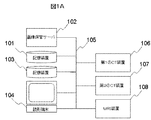
- FIG. 1A is a configuration diagram illustrating an example of an image diagnosis support system according to the first embodiment.
- reference numeral 101 denotes a storage device that mainly stores image data photographed by various inspection apparatuses (modalities) for image diagnosis.
- Reference numeral 102 denotes an image that stores and manages image data in the storage device 101 or the like. It is a storage server.
- reference numeral 103 denotes a storage device that stores information necessary for carrying out the processing of the image diagnosis support system of this embodiment, such as model images and parameters, as a database.
- Reference numeral 104 denotes an interpretation terminal including a display unit.
- the storage device 101 and the storage device 103 can be configured as storage units inside the image storage server 102 and the interpretation terminal 104, respectively.
- Reference numerals 106, 107, and 108 denote inspection apparatuses (modalities) for image diagnosis such as a first CT (Computed Tomography) apparatus, a second CT apparatus, and an MRI (Magnetic Resonance Imaging) apparatus, respectively. These various devices are all connected to each other via the network 105.
- the image storage server 102 and the image interpretation terminal 104 are both ordinary computers, and a central processing unit (Central Processing Unit: CPU) as an interconnected processing unit, a storage unit, a display unit, a keyboard, and the like are included therein. An input / output unit, a network interface, and the like are provided.
- CPU Central Processing Unit
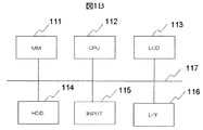
- FIG. 1B shows a specific example of the image interpretation terminal 104 in the image diagnosis support system of FIG. 1A, in which 111 is a main memory (MM) as a storage unit, 112 is a CPU, and 113 is a liquid crystal display (display unit). LCD), 114 is a hard disk drive (HDD), 115 is an input unit (INPUT) such as a keyboard, and 116 is a network interface (I / F). As described above, the HDD 114 can be used as the storage device 103 of the system shown in FIG.
- the configuration of the image storage server 102 has the same configuration and will not be described in detail. However, as described above, the internal HDD may be used as the storage device 101 of the system of FIG. 1A.
- the image diagnosis support system first, using the input unit 115 of the image interpretation terminal 104, registration processing is performed according to the inspection purpose, the inspection technique (modality), the inspection technique such as the imaging method, and the element of the attention site. Set the parameters independently.
- FIG. 2 is a flowchart showing a processing procedure of registration processing in the interpretation terminal 104 of the system of the present embodiment.
- FIG. 3 is a schematic diagram for explaining the registration process in the system of the present embodiment, and 301 is a processing unit that performs the registration process.
- This processing unit 301 corresponds to the CPU 112 of the image interpretation terminal 104 in FIG. 1B.
- the processing unit 301 reads each element described above from the database of the storage device 103 based on a user instruction input from the input unit 115 of the interpretation terminal 104.
- the inspection technique that is, the inspection device, the imaging method 302, the inspection purpose 303, and the region of interest 304 are read (202) and stored in the storage unit inside the image interpretation terminal 104.
- the image interpretation terminal 104 reads the image data 1 and the image data 2 from the inspection device stored in the storage device 101 (203, 204), and stores them in the internal storage unit.
- the image data 1 is image data to be overlaid
- the image data 2 is image data to be overlaid.
- the processing unit 301 of the image interpretation terminal 104 determines a model image candidate from the previously input inspection purpose and target region (205).
- the model image data is stored in the storage device 103 in association with the inspection purpose and the region of interest, as illustrated in FIG.
- the attention site 304 refers to the head, chest, back, abdomen, upper limbs, lower limbs, cerebral cortex, brain stem, lung, heart, liver, kidney, etc. There are organs.
- the parameter setting unit 3013 of the processing unit 301 determines a parameter set (PS) from the image data 1 and the inspection technique of each model image candidate (206). A method for determining the parameter set (PS) will be described later with reference to FIG.
- each model image is moved, scaled, rotated, or deformed with respect to the entire image between the image data 1 and each model image candidate, and the image data 1 Registration processing is executed (207), and it is determined whether there is a model image for which the registration processing is successful (208).
- the model image candidate data is sequentially read out from the storage device 103 based on the model image ID 404, so that the registration process between the image data 1 and the model image candidate can proceed. A method for determining whether or not the registration process has succeeded will be described later.
- the registration reference area is set using the model image that has been successfully registered. If there are a plurality of successful model images, first, a model image having the maximum mutual information amount and a more matched part shape is selected (209). In other words, the model image candidate having the maximum mutual information amount is selected from among a plurality of model image candidates including part deformation and defect. Then, the region on the image data 1 corresponding to the reference region for the alignment of the target region preset in the selected model image is registered for registration processing between the image data 1 and the image data 2. A reference area is set (210).
- registration processing parameters are determined from the inspection procedure of the image data 1 to be overlaid and the image data 2 to be overlaid, that is, the inspection device and the photographing method (211). Then, using the determined parameters, registration processing of the image data 1 and the image data 2 is executed (212), a registration image 307 is obtained, and the processing ends (213).
- the parameter determination and registration processing in steps 211 and 212 are performed in the same manner as the registration processing with the model image candidate. Specifically, assuming that the model image candidate is the image data 2, registration between the image data 1 and the image data 2 is performed. However, although registration processing is performed on the entire image in step 207, registration is performed so that the reference area for alignment is displayed at the same position. Also, a parameter set is selected from the inspection procedure of the image data 1 and the image data 2. In the registration process, for example, the image data 2 is rotated and the magnification is determined so that the mutual information amount is maximized.
- the registration process in step 212 will be described in detail.
- the registration process assuming that the shape of the object does not change, it is assumed that the registration is performed by moving, scaling, and rotating one of the images. It is roughly divided into non-rigid registration that also performs deformation processing.
- the rigid registration is performed, the image data 2 is moved, scaled, and rotated so that at least the alignment reference area is displayed at the same position.
- a portion of image data 2 corresponding to the alignment reference area set in image data 1 so that at least the alignment reference area is displayed at the same position Move, scale, and rotate the.
- the image data 2 there may be a clear boundary inside and outside the reference area. In order to reduce this boundary, the mutual information amount weighted according to the pixel position from the inside to the outside of the reference area is used.
- step 208 if there is no model image that succeeds in the registration processing in step 208, a new reference region for alignment is set on the image data 1 to be overlaid (214), and the image data 1 is added to the model image candidate (215), and step 205 and subsequent steps are executed.
- the registration process is executed by newly adding a model image using the captured image data.
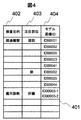
- FIG. 4 shows an example of the model image candidate table 401 used in the image diagnosis support system of the present embodiment.
- the model image candidate table 401 is stored in the storage device 103, and a model image can be selected by selecting a model image candidate from the inspection purpose 402 and the region of interest 403.
- the inspection purpose 402 includes postoperative evaluation, follow-up observation, identification diagnosis, and the like.
- the modality and the imaging method may be the same or different.
- follow-up observation there are many cases where the modality and the photographing method are basically the same.
- differential diagnosis there are many cases where either or both of the modality and the imaging technique are basically different.
- the region of interest 403 is exemplified by the head, lungs, and liver.
- the model image ID 404 stores an identifier (ID) corresponding to each model image. Note that the corresponding model image IDs 00003-1 and 00003-2 are assigned to the inspection purpose 402 and the target region 403. This is an example in which model images composed of a plurality of images are managed as a group of model images. This will be described later with reference to FIG.
- FIG. 5 shows an example of a parameter set (PS) setting table 501 used in the image diagnosis support system of this embodiment.
- the PS setting table 501 is stored in the storage device 103, and is a table for determining a parameter set by an inspection technique, that is, an inspection device and an imaging technique. Show.
- an inspection technique that is, an inspection device and an imaging technique.
- simple CT, contrast CT, MR (T1), MR (T2), MR (contrast), and MR (MRA) are illustrated as inspection techniques.
- a parameter set (PS) can be set.
- the parameter set (PS) can be determined by combining the inspection techniques of the image data 1 and the model image.
- the parameters in the system of the present embodiment include, for example, the size of sampling, the type of filter such as a Gaussian filter that smooths the image, the coefficient, the applied amount, and the number of times of rough registration performed as preprocessing.
- the resolution of the histogram when calculating the mutual information amount the set value such as the moving width of the image and the truncation error in the sequential processing when aligning.
- the processing unit 301 of the diagnostic imaging support system of this embodiment determines a model image 3011, performs parameter setting 3013, executes registration (3014), and then performs parameter correction. Execute (3012).
- the parameter correction 3012 the parameter setting contents are corrected in accordance with the change item and the mutual information amount that are the results of past registration processing. Then, a maximum value is set so that correction is not excessive, or the amount to be reflected is gradually increased or decreased.
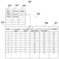
- FIG. 6 shows an example of an execution result accumulation table 601 for accumulating past registration process execution results stored in the storage device 103.
- This execution result accumulation table is prepared for each parameter set corresponding to each combination of inspection techniques shown in FIG.
- reference numerals 602, 603, and 604 indicate a model image ID, registration date and time, and the number of times of application, respectively.
- Reference numerals 605, 606, and 607 denote the process IDs, the parameters, and the mutual information amount of application times corresponding to the model image ID ID00001 of 10 times.
- As parameters a set of initial values and corrected application values of the sampling interval and Gaussian filter application amount are stored.
- the mutual information amount 607 is normalized from 0 to 1, and the value increases as the shape of the part more matches.
- FIG. 7 is a diagram for explaining an example of the parameter correction 3012 of FIG. 3 in the present embodiment.
- the horizontal axis indicates the normalized mutual information
- the vertical axis indicates the coefficient X.
- correction can be prevented from becoming excessive by providing a maximum value or gradually increasing or decreasing the amount to be reflected.
- the new initial value is determined by Equation 1 below.
- New initial value current initial value + (current initial value ⁇ applied value) ⁇ coefficient X (Formula 1)
- the coefficient X in the above equation is the value on the vertical axis in FIG.
- the parameter correction (3012) can be executed so as to reflect the correction as between the process ID 5 and the process ID 6.
- the sampling interval is updated as between the process ID 8 and the process ID 9
- all the initial values can be changed to the immediately preceding set values.
- the change in the sampling interval is not linearly related to other processing parameters. Therefore, such a change is performed instead of the above-described correction in which the value is gradually increased or decreased. In this way, appropriate correction can be applied for each parameter type, and there is a remarkable effect that alignment between images can be performed more quickly, more accurately, and more easily.
- FIGS. 8A and 8B show examples of model images in this example.
- the processing unit 301 of the above-described image diagnosis support system needs to be able to register and manage model images according to the inspection purpose and the region of interest in the registration process, which is registration between images.
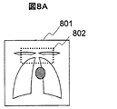
- the model images shown in FIGS. 8A and 8B show model images 801 and 803 of the entire lung field of the human body that is the subject. In this way, if the registration process for the image of the lung of interest is performed on the entire lung field, it becomes more susceptible to respiration. By matching, it is possible to improve the accuracy of registration processing, which is alignment between images.
- FIG. 8A in the model image 801, the position of a tissue such as an upper rib with little body movement due to respiration is used as a reference area 802 for alignment, and this reference area 802 is matched. Further, as shown in FIG. 8B, in the model image 803, when diagnosing bronchi, bronchial branch positions are set as reference areas 804-1 to 804-5, and these reference areas match as much as possible. By matching in this way, it is possible to improve the accuracy of registration processing, which is alignment between images.
- the alignment other than the reference region for alignment does not always match the alignment between images.
- this is not a big problem depending on the inspection purpose. For example, when interpreting the entire lung field described above, there is a shift between images due to the influence of breathing and heartbeat except for the reference area, but these movements are the original movements of the human body. , Interpretation can often be performed while predicting it, and it does not become a big problem depending on the inspection purpose.
- model images can be registered and managed according to the purpose of the examination and the region of interest. For example, when interpreting the entire lung field such as lung cancer, attention was paid to the entire lung field and bronchitis. When interpreting images, it is possible to select an appropriate model image according to the purpose of the examination and the site of interest, such as the branching position of the bronchus. This improves the accuracy of the registration process for determining the site of interest. In addition, there is a remarkable effect that registration between images focused on a target region can be performed in a shorter time, more accurately, and more easily.
- model images with different reference areas for registration can be registered and managed according to the inspection purpose and the target region. Therefore, it is possible to set a reference region that is different from the region of interest according to the purpose of the examination. For example, in the case of the entire lung field, the upper ribs and other tissues with little body movement due to breathing are set as a reference. Thus, it is possible to perform registration processing that is useful for diagnosis and the like, and there is a remarkable effect that registration between images focusing on the region of interest can be performed more quickly, more accurately, and more easily.
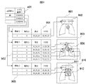
- FIG. 9 shows a state where the model image data in FIGS. 8A and 8B is stored in the storage device 103 of the image diagnosis support system in FIG.
- the reference area for alignment in the model image is expressed by area data of an area surrounded by a rectangle.
- the region of interest is the lung
- model images ID00002 and ID0205 indicate the data of the reference regions 802 and 804 for the alignment of the model images in FIGS. 8A and 8B, respectively.
- the storage device 103 stores region data 901 and 902 corresponding to the reference regions 802 and 804 for the alignment of the model images.
- Each of the area data 901 and 902 includes an area ID, a type ID, an origin, and a size.
- the region ID is an ID for identifying a reference region for alignment in the model image.
- “0” indicates an additional area and “1” indicates a deletion area.
- the origin is the origin of the reference area, and the size indicates the size of the reference area.
- the area IDs corresponding to the reference areas 804-1 to 804-5 for alignment are 1 to 5.
- the area data 903 is data related to the second embodiment, and will be described later.
- FIG. 10 is a diagram for explaining an example of a reference region for alignment of a target region and a three-dimensional data management method for a model image.
- FIGS. 8A to 8E and FIG. 9, for simplification of illustration it has been described as two-dimensional image data indicating a model image of a predetermined plane of a three-dimensional coordinate system.
- image data obtained from an inspection device is three-dimensional data. Therefore, in FIG. 10, a rectangular reference area 1002 is schematically shown in a captured image area 1001 formed with reference to the origin (0, 0, 0) of the XYZ three-dimensional coordinate system of the image.
- the rectangular reference area 1002 has an origin (x0, y0, z0) and a size (x1, y1, z1).
- a parameter set corresponding to the combination of the inspection techniques for the image to be registered is prepared. Therefore, an appropriate parameter is set for each combination of the inspection techniques in the registration process. As a result, it is possible to perform registration between images in a shorter time, more accurately, and more easily.
- model images can be registered and managed according to the inspection purpose and target region, it is possible to select an appropriate model image according to the inspection purpose and target region. There is a remarkable effect that registration between images can be performed in a shorter time, more accurately, and more easily.
- each model image is moved, enlarged / reduced, rotated, or deformed with respect to the entire image.
- the image data 1 may be adjusted by another method. For example, when only a specific part with relatively little deformation such as the head is targeted, the registration may be performed using a rigid registration process that does not perform the deformation process, or the entire image may be registered. Instead of performing the registration, a registration process may be performed only on a reference region for alignment preset in model image candidates. The processing procedure can be optimized according to the characteristics of the target image data and model image candidates.
- the second embodiment is an image diagnosis support system that automatically sets a reference region for alignment of a region of interest by automatically selecting an optimal one from a plurality of model images including deformation and defect of the region. is there. That is, an image diagnosis support apparatus that supports image diagnosis by registration processing between a plurality of images, and includes a processing unit that executes registration processing and a storage unit that stores a model image used for registration processing.
- the processing unit sets a reference region for alignment of the target region by automatically selecting from a plurality of model images including deformations and defects of the region in the image, and sets the reference region for the set alignment and a plurality of It is the Example regarding the image diagnosis assistance apparatus of the structure which performs the registration process between several images using the parameter of the registration process determined based on the test
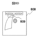
- FIGS. 8C, 8D, and 8E show model images as in FIG. 8A, but FIGS. 8C and 8D show examples in which model images 805 and 808 are newly added.
- FIG. 8E shows that the user can interactively set the image of the region of interest when a model image 810 is newly created.
- FIG. 8C when the heart 806 is large and the size of the reference region 802 for alignment in the model image 801 on the database is large and the heart 806 cannot be separated, the upper region is changed to the reference region 807 for alignment. By setting, a model image 805 that reduces the influence of individual differences can be added. Further, in FIG. 8D, when there is a past disease and one of the lungs is removed, a model image 808 for reducing the influence of treatment is added by setting only one lung as the reference region 809 for alignment. be able to.
- FIG. 8E shows a model image 810 obtained by removing a part of the reference region for alignment of the target region by interactively specifying the region to be separated from the reference region for alignment of the target region of the existing model image. It is a figure which shows the case where it adds newly. That is, by designating a region 812 that is desired to be separated from the existing reference region alignment of the target region, a part of the region can be removed and used as a new region reference region 811.
- the area data 903 of the model image 810 stores the area of the reference area 811 for alignment, the area ID1 corresponding to the area 812 to be separated, the type ID of ID2, the origin, and the size, respectively.
- the region to be separated can be specified interactively by combining rectangular regions in this way, it is difficult to specify in one rectangular region such as a part surrounded by other organs or a part inside a complicated body.
- the attention area can be specified, and various model images can be added and used, making it possible to perform alignment between images in a shorter time, more accurately, and more easily. effective.
- the designation and addition of the reference region for the alignment of the region of interest shown in the present embodiment can be performed in steps 214 and 215 in FIG. 2 described in the first embodiment.
- the initial parameter value of the registration process for the newly added model image is determined based on the value set for the same inspection technique image.
- an image diagnosis support system capable of determining the success or failure of the registration process by the value of the mutual information amount in the sequential process in the alignment, and further by the change will be described. That is, an image in which the processing unit of the image diagnosis support apparatus described above determines whether or not the registration process executed between the model image candidate and the first image is successful based on the mutual information value obtained by the registration process. It is an Example regarding a diagnosis assistance apparatus. Since the system configuration itself is not changed from the system of the above-described embodiment, the description is omitted here.
- FIG. 11 shows a graph for explaining determination of success or failure of the registration process in the present embodiment.
- the horizontal axis of the graph in the figure represents the number of registration processes in the registration process, and the vertical axis represents the mutual information amount.
- a graph 1101 shows the mutual information amount when the inspection technique and the attention site match
- the graph 1102 shows the mutual information amount when only the attention site matches.
- Reference numeral 1103 denotes a mutual information threshold value for determining the success or failure of alignment.
- the mutual information amount tends to increase as the number of alignment processes increases.
- the processing unit 301 in the image interpretation terminal 104 determines that the registration process is successful. If the mutual information amount does not change at all even if the number of alignment processes is increased, the processing unit 301 reconfirms whether the same processing result is obtained even if one image is forcibly moved. You can also. In the case of the graph 1101 in which the inspection technique and the attention site match between the images, the threshold value of the mutual information amount for success / failure determination is set high (1104).
- success / failure determination may be performed in combination with other indicators. For example, using the information on the change in the mutual information amount with respect to the number of processing times, a condition that the change is successful is added when the change is equal to or less than a preset threshold value. Thereby, there is an effect that the accuracy of success / failure determination can be improved.
- model image has been described in principle as being formed corresponding to each inspection device and imaging method.
- FIG. 12 is a schematic diagram showing an example of a case where model images composed of two types of images are managed as a group of model images as a modified example.
- a plurality of images for example, a CT image and a contrast CT image, which are different in imaging method in one examination, such as a liver examination, are taken and diagnosed with the results. Therefore, the model image 1201 of the CT image and the model image 1202 of the contrast CT image are managed together. Therefore, the model image ID 00003-1 of the CT image and the model image ID 00003-2 of the contrast CT image are managed respectively.
- Reference numeral 1203 denotes the liver, and 1204 denotes the portal vein.
- a new model image 1205 having a model image ID00003 obtained by superimposing both model images 1201 and 1202 can be created and used as a model image.
- the same model image can be applied to multiple images with different shooting methods, the cost of model image management and registration processing can be reduced, and alignment between images can be performed in a shorter time, more accurately, and more. There is a remarkable effect that it can be easily implemented.
- PS dedicated parameter set
- an image diagnosis support system capable of optimizing the registration processing parameter set (PS) used in the above-described embodiments among a plurality of hospitals.
- PS registration processing parameter set
- DB database
- FIG. 13 is a diagram schematically showing a system configuration related to the fourth embodiment.
- a plurality of hospitals A 1301 and B 1302 an inspection device A and an inspection device B that perform image diagnosis operate, and acquire an image A 1308 and an image B 1307, respectively.
- the plurality of hospitals A1301 and B1302 are connected to the service center 1305 via a network or the like (not shown) and can transmit and receive various data.
- the service center 1305 includes a server (not shown) having a normal computer configuration, that is, a processing unit, a storage unit, an input / output unit, a network interface unit, and the like that are connected to each other.
- the model image, parameter setting data, various types of inspection device information, and information on the inspection device master are stored.
- FIG. 15 is a timing chart showing an example of the procedure of registration processing of images taken by hospital A 1301 and hospital B 1302 in the system using the service center shown in FIG.
- the hospital A 1301 transmits a parameter set (PSa) related to the imaging method using the devices A and B to the service center 1305 (1501).
- PSa parameter set
- the service center 1305 stores the received PSa in the storage unit of the server inside the center.
- the hospital B1302 transmits a parameter set (PSb) related to the imaging method when the patient is imaged using the device A of the hospital B1302, to the service center 1305 (1502), the service center 1305 transmits the received PSb to the center.
- PSb parameter set
- the hospital B 1302 since the hospital B 1302 does not have the device B, the patient is introduced to the hospital A 1301, the imaging is performed by the device B, and the captured image B is transmitted to the hospital 1302 (1503).
- Hospital B which has received this captured image B, makes an inquiry to the service center 1305 as to whether or not there is a parameter set related to the imaging method using devices A and B (1504).
- the service center 1305 confirms the presence of the PSa and replies to the hospital B if the PSa exists (1505). In response to this reply, Hospital B 1302 requests the service center 1305 to transmit the parameter set (1506) and receives PSa (1507). As a result, the hospital B can perform registration processing between the image captured by the device A of the hospital B 1302 and the image captured by the device B of the hospital A 1301 using the received PSa.
- a CT apparatus can be assumed as the device A, and an MRI apparatus can be assumed as the device B.
- the number of MRI apparatuses and the diffusion rate are lower than those of CT apparatuses, it is possible to assume a case where a patient is introduced to a hospital with an MRI apparatus and an examination is performed. Thereby, for example, follow-up observation using an image taken at a facility where surgery is performed can be made possible in other different hospitals.
- the batch processing of the parameter set in the service center makes it possible to apply the optimum processing parameters to the images taken at other hospitals. It is possible to perform parameter optimization, and even when using images taken at other hospitals, it is possible to perform registration between images in a shorter time, more accurately, and more easily. There is.
- an image diagnosis support system capable of performing registration processing at the time of inspection and providing feedback to imaging conditions for the inspection equipment will be described.
- the result of the registration process is displayed on the inspection device immediately after photographing, and it is possible to immediately determine whether or not the amount of deformation of the image in the region of interest is large and provide feedback. .
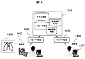
- 1401 is a parameter management server
- 1402 and 1403 are examination rooms and interpretation rooms connected to the parameter management server 1401 via a network (not shown)
- 1406 is a model image
- 1407 is an interpretation terminal. Show.
- the laboratory technician in the examination room 1402 transmits the image A of the patient A taken using the examination device 1406 in the examination room 1402 to the interpretation room 1403 (1601).
- the interpretation doctor interprets the image A using the interpretation terminal 1407, and transmits the parameter setting 1405 of the registration processing performed at that time to the parameter management server 1401 (1602).
- the parameter management server 1401 optimizes processing parameters and stores them as parameter sets.
- the parameter management server 1601 calls the parameter set relating to the imaging device and imaging method that captured the image A (1604), and receives the transmitted parameter set (1605).
- the examination room 1402 registration processing between the image A and the image B taken this time is performed using the received parameter set. If the registration process is not successful, the examination room 1402 changes the patient's posture and imaging conditions, and re-executes imaging and registration processes. Then, the captured image B is transmitted to the interpretation room 1403 (1606), and the parameters of the registered registration processing are transmitted to the parameter management server 1401 (1607).
- the parameter management server 1401 optimizes the transmitted processing parameters and stores them in the storage unit as a parameter set.
- the interpretation doctor in the interpretation room 1403 uses the interpretation terminal 1407 to call a parameter set relating to the examined imaging apparatus and imaging method from the parameter management server 1401, and uses the transmitted parameter set to register the images A and B. Processing can be performed to interpret image B.
- the parameter management server 1401 can share all in-hospital processing parameters, and the registration process using all in-hospital cases can be performed also in the laboratory. Since the parameter set can be used immediately, there is a remarkable effect that registration between images can be performed in a shorter time, more accurately, and more easily. In addition, if the compared image has a large amount of deformation, it can be immediately re-photographed, or it can be reflected in setting of the imaging conditions of the inspection device (modality) and re-photographing. In addition, it is possible to prevent a case in which re-photographing is required at a later date, and to reduce the burden on the patient.
- FIG. 17 is a diagram illustrating an example of a registration processing screen in each of the above-described embodiments.
- image data 1 17 1701, image data 2 1702, and registration result image 1703 are displayed on a screen 1711.
- an automatic parameter setting button 1704 is arranged. By this button, execution of automatic parameter setting according to the above-described embodiments is started.
- the parameter correction button 1705 is selected when a problem occurs during automatic setting.
- a pull-down menu 1706 is a parameter setting unit that can be changed when parameter correction is selected, such as a preprocessing filter, application amount, sequential processing step, and truncation error.
- a registration execution button 1707 is a button for executing a registration process for combining the image data 2 1702 with the image data 1 1701.
- the image data 2 only button 1708 is a button for displaying only the processing result of the image data 2 on the registration result image.
- the overlay display button 1709 is a button for displaying the image data 1 and the image data 2 after registration processing on the same screen.
- the brightness / hue slider 1710 is a slider for changing the brightness and hue of the image data 2 in the superimposed display.
- this invention is not limited to the above-mentioned Example, Various modifications are included.
- the above-described embodiments have been described in detail in order to explain the present invention in an easy-to-understand manner, and are not necessarily limited to those having all the configurations described.
- a part of the configuration of one embodiment can be replaced with the configuration of another embodiment, and the configuration of another embodiment can be added to the configuration of one embodiment.
- each of the above-described configurations, functions, processing units, processing means, and the like may be realized by hardware by designing a part or all of them with, for example, an integrated circuit.
- each of the above-described configurations, functions, and the like may be realized by software by interpreting and executing a program that realizes each function.
- Information such as programs, tables, and files for realizing each function may be stored in a memory, a hard disk, a storage device such as SSD (Solid State Drive), or a recording medium such as an IC card or DVD (Digital Versatile Disc). It can also be downloaded via a network or the like as necessary.
- the present invention is extremely useful as an image diagnosis support apparatus, in particular, as a technique for improving the efficiency of registration processing between images when a plurality of images are compared and interpreted.
Landscapes
- Engineering & Computer Science (AREA)
- Health & Medical Sciences (AREA)
- Physics & Mathematics (AREA)
- Life Sciences & Earth Sciences (AREA)
- Nuclear Medicine, Radiotherapy & Molecular Imaging (AREA)
- General Health & Medical Sciences (AREA)
- Computer Vision & Pattern Recognition (AREA)
- Medical Informatics (AREA)
- General Physics & Mathematics (AREA)
- Radiology & Medical Imaging (AREA)
- Theoretical Computer Science (AREA)
- Pathology (AREA)
- Surgery (AREA)
- Biophysics (AREA)
- Quality & Reliability (AREA)
- Biomedical Technology (AREA)
- Heart & Thoracic Surgery (AREA)
- Molecular Biology (AREA)
- High Energy & Nuclear Physics (AREA)
- Animal Behavior & Ethology (AREA)
- Public Health (AREA)
- Veterinary Medicine (AREA)
- Apparatus For Radiation Diagnosis (AREA)
- Measuring And Recording Apparatus For Diagnosis (AREA)
- Magnetic Resonance Imaging Apparatus (AREA)
Abstract
La présente invention concerne des améliorations apportées à l'efficacité des positionnements relatifs entre images quand on compare entre elles une pluralité d'images pour réaliser une interprétation d'images radiographiques au moyen d'un appareil d'aide au diagnostic par imagerie. Ainsi, selon l'invention, un tel appareil d'aide au diagnostic par imagerie, qui aide au diagnostic par imagerie au moyen d'un calage relatif entre une pluralité d'images, comprend: un terminal d'interprétation d'images radiographiques (104) chargé d'exécuter le calage; et des dispositifs de mémoire de stockage (101, 103) servant à stocker des images modèles et analogues à utiliser pour le calage. Le terminal d'interprétation d'images radiographiques (104) exécute un calage relatif les différentes images au moyen, d'une part d'une zone de référence de positionnement qui a été définie au préalable dans une image modèle choisie sur la base, non seulement de la raison pour laquelle on vérifie la pluralité d'images, mais aussi du choix de la partie examinée, et d'autre part de paramètres de calage déterminés sur la base d'une manipulation permettant de vérifier la pluralité d'images.
Priority Applications (4)
| Application Number | Priority Date | Filing Date | Title |
|---|---|---|---|
| CN201280028495.8A CN103596489A (zh) | 2011-06-10 | 2012-05-22 | 图像诊断支持装置、以及方法 |
| EP12797081.2A EP2719325A1 (fr) | 2011-06-10 | 2012-05-22 | Appareil d'aide au diagnostic par imagerie, et procédé correspondant |
| US14/124,820 US20140126789A1 (en) | 2011-06-10 | 2012-05-22 | Image diagnosis assisting apparatus, and method |
| JP2013519434A JP5684382B2 (ja) | 2011-06-10 | 2012-05-22 | 画像診断支援装置、及び方法 |
Applications Claiming Priority (2)
| Application Number | Priority Date | Filing Date | Title |
|---|---|---|---|
| JP2011-130254 | 2011-06-10 | ||
| JP2011130254 | 2011-06-10 |
Publications (1)
| Publication Number | Publication Date |
|---|---|
| WO2012169344A1 true WO2012169344A1 (fr) | 2012-12-13 |
Family
ID=47295913
Family Applications (1)
| Application Number | Title | Priority Date | Filing Date |
|---|---|---|---|
| PCT/JP2012/063097 Ceased WO2012169344A1 (fr) | 2011-06-10 | 2012-05-22 | Appareil d'aide au diagnostic par imagerie, et procédé correspondant |
Country Status (5)
| Country | Link |
|---|---|
| US (1) | US20140126789A1 (fr) |
| EP (1) | EP2719325A1 (fr) |
| JP (1) | JP5684382B2 (fr) |
| CN (1) | CN103596489A (fr) |
| WO (1) | WO2012169344A1 (fr) |
Cited By (10)
| Publication number | Priority date | Publication date | Assignee | Title |
|---|---|---|---|---|
| JP2014183924A (ja) * | 2013-03-22 | 2014-10-02 | Advanced Telecommunication Research Institute International | 脳活動測定装置および脳活動測定方法 |
| JP2016039878A (ja) * | 2014-08-13 | 2016-03-24 | 株式会社東芝 | 放射線治療システム |
| JP2016101502A (ja) * | 2014-11-28 | 2016-06-02 | 株式会社東芝 | 医用画像処理装置 |
| CN106462971A (zh) * | 2014-06-25 | 2017-02-22 | 皇家飞利浦有限公司 | 用于配准不同成像模态的成像设备 |
| WO2018096639A1 (fr) * | 2016-11-24 | 2018-05-31 | 株式会社ニコン | Dispositif de traitement d'image, système de microscope, procédé de traitement d'image et programme |
| JP2018153297A (ja) * | 2017-03-16 | 2018-10-04 | コニカミノルタ株式会社 | X線動画像処理装置 |
| JP2018164533A (ja) * | 2017-03-28 | 2018-10-25 | キヤノンメディカルシステムズ株式会社 | 医用画像処理装置、医用画像処理方法、及び医用画像処理プログラム |
| JP2019032600A (ja) * | 2017-08-04 | 2019-02-28 | 日本電気株式会社 | 三次元画像生成装置、三次元画像生成方法、および三次元画像生成プログラム |
| JP2020086698A (ja) * | 2018-11-20 | 2020-06-04 | 株式会社アルム | 画像処理装置、画像処理システム、および画像処理プログラム |
| JP2022021076A (ja) * | 2020-07-21 | 2022-02-02 | 浜松ホトニクス株式会社 | 脳画像診断システム及び脳画像診断方法 |
Families Citing this family (9)
| Publication number | Priority date | Publication date | Assignee | Title |
|---|---|---|---|---|
| WO2012169344A1 (fr) * | 2011-06-10 | 2012-12-13 | 株式会社日立メディコ | Appareil d'aide au diagnostic par imagerie, et procédé correspondant |
| JP5948200B2 (ja) * | 2012-09-27 | 2016-07-06 | オリンパス株式会社 | 画像処理装置、プログラム及び画像処理方法 |
| JP6242072B2 (ja) | 2012-09-27 | 2017-12-06 | オリンパス株式会社 | 画像処理装置、プログラム及び画像処理装置の作動方法 |
| EP3451343B1 (fr) * | 2013-09-25 | 2021-02-24 | Heartflow, Inc. | Systèmes et procédés de validation et de correction d'annotations d'images médicales automatisées |
| KR20150074304A (ko) * | 2013-12-23 | 2015-07-02 | 삼성전자주식회사 | 의료 영상 정보를 제공하는 방법 및 그 장치 |
| JP6376838B2 (ja) * | 2014-05-22 | 2018-08-22 | 富士フイルム株式会社 | 診療支援装置、診療支援装置の作動方法及びプログラム、並びに診療支援システム |
| DE102014223388B4 (de) * | 2014-11-17 | 2016-07-28 | Siemens Healthcare Gmbh | Beschleunigung einer MR-Fingerprinting-Messung |
| WO2019083983A2 (fr) | 2017-10-23 | 2019-05-02 | Bono Peter L | Instrument chirurgical oscillant/à mouvement de va-et-vient rotatif |
| JP7167615B2 (ja) * | 2018-10-05 | 2022-11-09 | コニカミノルタ株式会社 | 画像検査装置、画像検査方法及び画像検査プログラム |
Citations (3)
| Publication number | Priority date | Publication date | Assignee | Title |
|---|---|---|---|---|
| JPH08103439A (ja) * | 1994-10-04 | 1996-04-23 | Konica Corp | 画像の位置合わせ処理装置及び画像間処理装置 |
| JP2003517361A (ja) * | 1999-12-14 | 2003-05-27 | シーメンス コーポレイト リサーチ インコーポレイテツド | カーディアックcta及びmrデータ収集のモデルベースドレジストレーション |
| JP2007029502A (ja) * | 2005-07-28 | 2007-02-08 | Fujifilm Corp | 位置合せ装置、位置合せ方法、およびそのプログラム |
Family Cites Families (10)
| Publication number | Priority date | Publication date | Assignee | Title |
|---|---|---|---|---|
| US5273040A (en) * | 1991-11-14 | 1993-12-28 | Picker International, Inc. | Measurement of vetricle volumes with cardiac MRI |
| WO2001043070A2 (fr) * | 1999-12-10 | 2001-06-14 | Miller Michael I | Procede et appareil de calage d'images selon des modalites croisees |
| US20060074287A1 (en) * | 2004-09-30 | 2006-04-06 | General Electric Company | Systems, methods and apparatus for dual mammography image detection |
| EP1828981A2 (fr) * | 2004-12-15 | 2007-09-05 | Koninklijke Philips Electronics N.V. | Enregistrement d'images a modalites multiples |
| US8194946B2 (en) * | 2005-07-28 | 2012-06-05 | Fujifilm Corporation | Aligning apparatus, aligning method, and the program |
| US7995818B2 (en) * | 2006-11-22 | 2011-08-09 | General Electric Company | Systems and methods for synchronized image viewing with an image atlas |
| US20100318538A1 (en) * | 2009-06-12 | 2010-12-16 | Google Inc. | Predictive searching and associated cache management |
| US8311303B2 (en) * | 2010-01-12 | 2012-11-13 | Siemens Corporation | Method and system for semantics driven image registration |
| EP2369551B1 (fr) * | 2010-03-25 | 2019-10-30 | Emory University | Système et procédé d'imagerie |
| WO2012169344A1 (fr) * | 2011-06-10 | 2012-12-13 | 株式会社日立メディコ | Appareil d'aide au diagnostic par imagerie, et procédé correspondant |
-
2012
- 2012-05-22 WO PCT/JP2012/063097 patent/WO2012169344A1/fr not_active Ceased
- 2012-05-22 EP EP12797081.2A patent/EP2719325A1/fr not_active Withdrawn
- 2012-05-22 CN CN201280028495.8A patent/CN103596489A/zh active Pending
- 2012-05-22 US US14/124,820 patent/US20140126789A1/en not_active Abandoned
- 2012-05-22 JP JP2013519434A patent/JP5684382B2/ja not_active Expired - Fee Related
Patent Citations (3)
| Publication number | Priority date | Publication date | Assignee | Title |
|---|---|---|---|---|
| JPH08103439A (ja) * | 1994-10-04 | 1996-04-23 | Konica Corp | 画像の位置合わせ処理装置及び画像間処理装置 |
| JP2003517361A (ja) * | 1999-12-14 | 2003-05-27 | シーメンス コーポレイト リサーチ インコーポレイテツド | カーディアックcta及びmrデータ収集のモデルベースドレジストレーション |
| JP2007029502A (ja) * | 2005-07-28 | 2007-02-08 | Fujifilm Corp | 位置合せ装置、位置合せ方法、およびそのプログラム |
Non-Patent Citations (1)
| Title |
|---|
| JOURNAL OF INSTITUTE OF ELECTRONICS, INFORMATION AND COMMUNICATION ENGINEERS D-II, vol. J87-D-II, no. 10, October 2004 (2004-10-01), pages 1887 - 1920 |
Cited By (14)
| Publication number | Priority date | Publication date | Assignee | Title |
|---|---|---|---|---|
| JP2014183924A (ja) * | 2013-03-22 | 2014-10-02 | Advanced Telecommunication Research Institute International | 脳活動測定装置および脳活動測定方法 |
| CN106462971A (zh) * | 2014-06-25 | 2017-02-22 | 皇家飞利浦有限公司 | 用于配准不同成像模态的成像设备 |
| JP2017518826A (ja) * | 2014-06-25 | 2017-07-13 | コーニンクレッカ フィリップス エヌ ヴェKoninklijke Philips N.V. | 異なる撮像モダリティのレジストレーションのための撮像機器 |
| CN106462971B (zh) * | 2014-06-25 | 2021-01-26 | 皇家飞利浦有限公司 | 用于配准不同成像模态的成像设备 |
| JP2016039878A (ja) * | 2014-08-13 | 2016-03-24 | 株式会社東芝 | 放射線治療システム |
| JP2016101502A (ja) * | 2014-11-28 | 2016-06-02 | 株式会社東芝 | 医用画像処理装置 |
| JPWO2018096639A1 (ja) * | 2016-11-24 | 2019-10-17 | 株式会社ニコン | 画像処理装置、顕微鏡システム、画像処理方法、およびプログラム |
| WO2018096639A1 (fr) * | 2016-11-24 | 2018-05-31 | 株式会社ニコン | Dispositif de traitement d'image, système de microscope, procédé de traitement d'image et programme |
| US11010914B2 (en) | 2016-11-24 | 2021-05-18 | Nikon Corporation | Image processing device, microscope system, image processing method, and program |
| JP2018153297A (ja) * | 2017-03-16 | 2018-10-04 | コニカミノルタ株式会社 | X線動画像処理装置 |
| JP2018164533A (ja) * | 2017-03-28 | 2018-10-25 | キヤノンメディカルシステムズ株式会社 | 医用画像処理装置、医用画像処理方法、及び医用画像処理プログラム |
| JP2019032600A (ja) * | 2017-08-04 | 2019-02-28 | 日本電気株式会社 | 三次元画像生成装置、三次元画像生成方法、および三次元画像生成プログラム |
| JP2020086698A (ja) * | 2018-11-20 | 2020-06-04 | 株式会社アルム | 画像処理装置、画像処理システム、および画像処理プログラム |
| JP2022021076A (ja) * | 2020-07-21 | 2022-02-02 | 浜松ホトニクス株式会社 | 脳画像診断システム及び脳画像診断方法 |
Also Published As
| Publication number | Publication date |
|---|---|
| JPWO2012169344A1 (ja) | 2015-02-23 |
| CN103596489A (zh) | 2014-02-19 |
| EP2719325A1 (fr) | 2014-04-16 |
| US20140126789A1 (en) | 2014-05-08 |
| JP5684382B2 (ja) | 2015-03-11 |
Similar Documents
| Publication | Publication Date | Title |
|---|---|---|
| JP5684382B2 (ja) | 画像診断支援装置、及び方法 | |
| JP5572440B2 (ja) | 診断支援システム、診断支援プログラムおよび診断支援方法 | |
| JP5355110B2 (ja) | 診断支援装置及び診断支援方法 | |
| JP4818846B2 (ja) | 医用画像処理装置及び医用画像処理プログラム | |
| JP5159301B2 (ja) | 医用画像表示装置および画像表示方法 | |
| JP6738305B2 (ja) | 学習データ生成支援装置および学習データ生成支援装置の作動方法並びに学習データ生成支援プログラム | |
| EP2925216B1 (fr) | Planification d'une thérapie contre la sténose | |
| US8306292B2 (en) | Image display device and image display program storage medium | |
| JP2011160882A (ja) | 医用画像表示装置及び医用画像表示方法並びにプログラム | |
| JP2011092681A (ja) | 医用画像処理装置および方法並びにプログラム | |
| JP2011092687A (ja) | 診断支援システム、診断支援プログラムおよび診断支援方法 | |
| US11468659B2 (en) | Learning support device, learning support method, learning support program, region-of-interest discrimination device, region-of-interest discrimination method, region-of-interest discrimination program, and learned model | |
| JP6967983B2 (ja) | 画像処理装置、画像処理方法、及びプログラム | |
| WO2006011545A1 (fr) | Système d’assistance au diagnostic médical par image, dispositif et programme de traitement d’image | |
| JP5355111B2 (ja) | 診断支援装置及び診断支援方法 | |
| JP4911029B2 (ja) | 異常陰影候補検出方法、異常陰影候補検出装置 | |
| JP2016202721A (ja) | 医用画像表示装置及びプログラム | |
| JP2008307183A (ja) | 画像処理装置および画像処理プログラム | |
| CA3034814C (fr) | Systeme et methode d'utilisation du classement de mesure de qualite d'imagerie | |
| JP5923067B2 (ja) | 診断支援装置および診断支援方法並びに診断支援プログラム | |
| JP5750381B2 (ja) | 領域抽出処理システム | |
| JP5784082B2 (ja) | 診断支援装置及び診断支援方法 | |
| JP6645904B2 (ja) | 医用画像表示装置及び表示プログラム | |
| JP5533198B2 (ja) | 医用画像表示装置及びプログラム | |
| EP4621714A1 (fr) | Appareil, procédé et programme de traitement d'image |
Legal Events
| Date | Code | Title | Description |
|---|---|---|---|
| 121 | Ep: the epo has been informed by wipo that ep was designated in this application |
Ref document number: 12797081 Country of ref document: EP Kind code of ref document: A1 |
|
| ENP | Entry into the national phase |
Ref document number: 2013519434 Country of ref document: JP Kind code of ref document: A |
|
| WWE | Wipo information: entry into national phase |
Ref document number: 14124820 Country of ref document: US |
|
| NENP | Non-entry into the national phase |
Ref country code: DE |