WO2012169476A1 - Dispositif d'endoscope électronique et son procédé de fabrication - Google Patents
Dispositif d'endoscope électronique et son procédé de fabrication Download PDFInfo
- Publication number
- WO2012169476A1 WO2012169476A1 PCT/JP2012/064419 JP2012064419W WO2012169476A1 WO 2012169476 A1 WO2012169476 A1 WO 2012169476A1 JP 2012064419 W JP2012064419 W JP 2012064419W WO 2012169476 A1 WO2012169476 A1 WO 2012169476A1
- Authority
- WO
- WIPO (PCT)
- Prior art keywords
- optical member
- adhesive
- adhesive layer
- electronic endoscope
- peripheral surface
- Prior art date
- Legal status (The legal status is an assumption and is not a legal conclusion. Google has not performed a legal analysis and makes no representation as to the accuracy of the status listed.)
- Ceased
Links
Images


Classifications
-
- A—HUMAN NECESSITIES
- A61—MEDICAL OR VETERINARY SCIENCE; HYGIENE
- A61B—DIAGNOSIS; SURGERY; IDENTIFICATION
- A61B1/00—Instruments for performing medical examinations of the interior of cavities or tubes of the body by visual or photographical inspection, e.g. endoscopes; Illuminating arrangements therefor
- A61B1/00064—Constructional details of the endoscope body
- A61B1/00071—Insertion part of the endoscope body
- A61B1/0008—Insertion part of the endoscope body characterised by distal tip features
- A61B1/00096—Optical elements
-
- A—HUMAN NECESSITIES
- A61—MEDICAL OR VETERINARY SCIENCE; HYGIENE
- A61B—DIAGNOSIS; SURGERY; IDENTIFICATION
- A61B1/00—Instruments for performing medical examinations of the interior of cavities or tubes of the body by visual or photographical inspection, e.g. endoscopes; Illuminating arrangements therefor
- A61B1/00064—Constructional details of the endoscope body
- A61B1/0011—Manufacturing of endoscope parts
-
- G—PHYSICS
- G02—OPTICS
- G02B—OPTICAL ELEMENTS, SYSTEMS OR APPARATUS
- G02B23/00—Telescopes, e.g. binoculars; Periscopes; Instruments for viewing the inside of hollow bodies; Viewfinders; Optical aiming or sighting devices
- G02B23/24—Instruments or systems for viewing the inside of hollow bodies, e.g. fibrescopes
- G02B23/2407—Optical details
- G02B23/2423—Optical details of the distal end
-
- G—PHYSICS
- G02—OPTICS
- G02B—OPTICAL ELEMENTS, SYSTEMS OR APPARATUS
- G02B23/00—Telescopes, e.g. binoculars; Periscopes; Instruments for viewing the inside of hollow bodies; Viewfinders; Optical aiming or sighting devices
- G02B23/24—Instruments or systems for viewing the inside of hollow bodies, e.g. fibrescopes
- G02B23/2476—Non-optical details, e.g. housings, mountings, supports
- G02B23/2492—Arrangements for use in a hostile environment, e.g. a very hot, cold or radioactive environment
-
- G—PHYSICS
- G02—OPTICS
- G02B—OPTICAL ELEMENTS, SYSTEMS OR APPARATUS
- G02B23/00—Telescopes, e.g. binoculars; Periscopes; Instruments for viewing the inside of hollow bodies; Viewfinders; Optical aiming or sighting devices
- G02B23/24—Instruments or systems for viewing the inside of hollow bodies, e.g. fibrescopes
- G02B23/26—Instruments or systems for viewing the inside of hollow bodies, e.g. fibrescopes using light guides
Definitions
- the present invention relates to an electronic endoscope apparatus and a manufacturing method thereof.
- the endoscope has an insertion portion that is inserted into a body cavity, and an illumination optical system that emits illumination light to a subject and an imaging optical system that forms a subject image are provided at the distal end of the insertion portion.
- an illumination optical system that emits illumination light to a subject
- an imaging optical system that forms a subject image
- the lens 133 of the illumination optical system exposed to the outside at the distal end 131 of the insertion portion, the cover glass 135 of the imaging optical system as shown in FIG.
- a method of filling the gap between the optical member and the holding portion for storing the optical member with an adhesive 137 and fixing the optical member and the holding portion as a sealed structure is employed.
- an epoxy-based adhesive or a silicon-based adhesive is used for the gap between the side surface of the optical member and the holding portion.
- a bank scale 139 is provided on the outer peripheral edge outside the optical member for preventing flare, and a blackened epoxy adhesive is used for the bank bank 139.
- epoxy adhesives and silicon adhesives have relatively high moisture permeability, and moisture permeates into the layer of adhesive 137 when the endoscope is cleaned even in a sealed structure. For this reason, the cleaning material or the like may permeate into the endoscope and cause internal contamination.
- the epoxy adhesive does not necessarily have sufficient strength against rubbing during brush cleaning or wiping with gauze, and the epoxy embankment 139 is shaved, resulting in insufficient cutting of unnecessary light. There is a risk of moisture entering.
- Medical endoscope devices are washed, disinfected, and sterilized to remove attached contaminants each time they are inserted into a body cavity and used.
- an autoclave treatment for washing with high-temperature and high-pressure steam exceeding 100 ° C.
- Endoscope devices that are exposed to such severe conditions are particularly required to have further heat resistance and durability because the bonded portion is susceptible to damage such as thermal stress.
- the medical endoscope apparatus has electronic parts such as an image sensor mounted on the distal end portion of the endoscope insertion portion. For this reason, when moisture enters the electronic component during the autoclave process, the endoscope insertion portion fails and needs to be replaced. In medical endoscope devices, it is necessary to avoid situations where the endoscope insertion part is frequently replaced, and there is a need for the development of a device that does not break down even when exposed to harsh environments such as autoclaving. Yes.
- An object of the present invention is to provide an electronic endoscope apparatus capable of improving heat resistance and durability under severe conditions such as autoclaving and a method for manufacturing the same.
- the electronic endoscope apparatus includes an optical member and a distal end of an insertion portion in which a frame body made of a material having a different thermal expansion coefficient from the optical member and holding the optical member is inserted into a subject.
- the electronic endoscope device is disposed in a portion, and the tip portion includes an electronic component including an imaging device, and the optical member and the frame have three different thermal expansion coefficients. It is connected via the above adhesive layer.
- the second adhesive layer forming step is provided with a stepped portion whose diameter is increased by stepping at one end of the inner peripheral surface of the frame.
- the second adhesive layer is formed on the expanded inner peripheral surface of the expanded portion
- the third adhesive layer forming step includes a third adhesive layer on the outer side of the first adhesive layer.
- the outer peripheral surface of the optical member is transferred to a second adhesive layer formed on the enlarged inner peripheral surface of the stepped portion.
- the layer of the second adhesive material extends to the annular side surface formed by the step of the frame, and the outer surface of the optical member faces the outer surface.
- a gap between the diameter-enlarged inner peripheral surface of the attached portion and a gap between the annular side surface and the outer peripheral edge portion of the optical member facing the annular side surface Respect are those each forming a layer of the second adhesive over the entire circumference.
- the electronic endoscope apparatus of the present invention it is possible to improve heat resistance and durability under severe conditions such as autoclave processing.
- FIG. 3 is a schematic sectional view showing an AA section of FIG. 2.
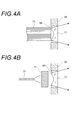
- A) is a schematic configuration diagram of an illumination optical system that guides outgoing light from a white light source to an endoscope tip portion by an optical fiber bundle
- B) is a diagram showing a laser beam emitted from the endoscope tip portion by a single optical fiber. It is a schematic block diagram of the illumination optical system which guides light to a fluorescent substance.
- FIG. 5 is a schematic cross-sectional view in which an optical member is fixed to an opening hole of a distal end hard portion through a plurality of adhesive layers.
- (A), (B), (C) is process drawing which shows the procedure which fixes an optical member to the opening hole of a front-end
- FIG. 4 is a schematic cross-sectional view in which an optical member is fixed to an opening hole of a distal end hard portion through three adhesive layers. It is a figure which shows the state which the crack generate
- FIG. 13 is an enlarged explanatory view showing an R portion of FIG. 12 in an enlarged manner.
- FIG. 6 is a diagram showing experimental examples of configuration examples 1 to 6 of a sealing structure of an optical member and a hard tip portion.
- A) is the block diagram which shows the junction structure of the lens of the conventional illumination optical system
- B) is the block diagram which shows the junction structure of the cover glass of the conventional imaging optical system.
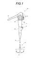
- FIG. 1 is a diagram for explaining an embodiment of the present invention.
- An endoscope 100 that is a medical device includes a main body operation unit 11 and an endoscope insertion unit 13 that is connected to the main body operation unit 11 and is inserted into a body cavity.
- a universal cord 15 is connected to the main body operation unit 11, and a light guide connector (not shown) is provided at the tip of the universal cord 15.
- the light guide connector is detachably connected to a light source device (not shown), whereby illumination light is sent to the illumination optical system of the distal end portion 17 of the endoscope insertion portion 13.
- an electrical connector is connected to the light guide connector, and this electrical connector is detachably coupled to a processor that performs image signal processing and the like.
- the endoscope insertion unit 13 includes a flexible portion 19, a bending portion 21, and a distal end portion (hereinafter also referred to as an endoscope distal end portion) 17 in order from the main body operation portion 11 side.
- the bending portion 21 is remotely bent by turning the angle knobs 23 and 25 of the main body operation portion 11, whereby the distal end portion 17 can be directed in a desired direction.
- the main body operation unit 11 is provided with various buttons 27 such as an air / water supply button, a suction button, and a shutter button in addition to the angle knobs 23 and 25 described above. Further, a forceps insertion portion 31 into which a treatment tool such as forceps is inserted is provided in the continuous portion 29 extended from the main body operation portion 11 to the endoscope insertion portion 13 side. The distal end of the treatment instrument inserted from the forceps insertion portion 31 is led out from a forceps port 41 (see FIG. 2) formed in the endoscope distal end portion 17.
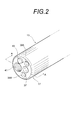
- FIG. 2 shows a schematic external view of the distal end portion of the endoscope.
- an observation window 37 of the imaging optical system and irradiation windows 39A and 39B of the illumination optical system are arranged on both sides of the observation window 37.
- a forceps port 41 and an air / water supply nozzle 43 for supplying or supplying air toward the observation window 37 are also arranged on the distal end surface.
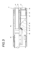
- FIG. 3 is a schematic cross-sectional view showing the AA cross section of FIG.
- the endoscope distal end portion 17 has a distal end hard portion 45 made of a metal material such as a stainless steel material or ceramics.
- the lens barrel 51 of the imaging unit 49 is inserted into the opening hole 47 formed in the distal end hard portion 45, and the imaging optical system is arranged.
- the imaging unit 49 bends the optical axis of the lens barrel 51 at a right angle by the prism 53 and forms an image on the imaging element 57 mounted on the substrate 55.
- An imaging signal from the imaging element 57 is transmitted from the substrate 55 to a control device (not shown) through a signal line 59.
- a cover glass 61 is provided in front of the optical path of the lens barrel 51, and a sealed structure is formed between the distal end hard portion 45.
- a lens that emits illumination light from the endoscope distal end portion 17 to the opening hole 69 formed in the distal end rigid portion 45. 71 is inserted.
- the illumination optical system is configured to guide the emitted light from a white light source such as a xenon lamp or a halogen lamp to the endoscope distal end portion 17 by the optical fiber bundle 73 (FIG. 4A), the optical fiber bundle 73
- the lens 71 is arranged at the light emitting end.
- the laser light is guided to the endoscope distal end portion 17 by a single optical fiber 75, and a phosphor 77 is disposed at the light emitting end of the optical fiber 75, so that the fluorescence from the phosphor 77 excited by the laser light can be obtained.
- the lens 71 is arranged on the opposite side of the phosphor 77 from the laser light incident side. In either case, a sealed structure is formed between the lens 71 and the distal end hard portion 45.
- a metal forceps pipe 65 is fixedly provided in the opening hole 63 formed in the distal end hard portion 45, and a forceps is provided at the end of the forceps pipe 65 opposite to the opening hole 63.
- a tube 67 is connected.
- the forceps pipe 65 and the forceps tube 67 form a forceps channel that communicates from the forceps port 41 of the endoscope distal end portion 17 to the forceps insertion portion 31 on the main body operation portion 11 side.
- FIG. 5 is a schematic sectional view in which the optical member 83 (61, 71) is fixed to the opening hole 81 (47, 69) of the distal end hard portion 45 via a plurality of adhesive layers.
- the shape of the distal end hard portion 45 is simplified to a simple cylindrical shape.
- an optical member such as a lens or a translucent cover plate is exposed on the surface of the endoscope front end portion.
- the optical member 83 is held in the opening hole 81 of the distal end hard portion 45, which is a frame, and the optical member 83 and the opening hole 81 are connected via a plurality of adhesive layers 85 having different thermal expansion coefficients. .
- the plurality of adhesive layers 85 are stacked in the gap between the optical member 83 and the opening hole 81 in the thickness direction of the gap.
- the adhesive layer 85 includes a first adhesive layer 87 on the optical member side and a second adhesive layer 89 on the opening hole 81 side.
- the first adhesive layer 87 is formed on the outer peripheral surface of the optical member 83 formed in a plate shape, and the second adhesive layer 89 is formed on the inner peripheral surface of the opening hole 81 facing the outer peripheral surface.
- the first adhesive material layer 87 is made of a first adhesive material having a thermal expansion coefficient smaller than that of the hard end portion 45 and larger than that of the optical member 83.
- the second adhesive layer 89 is made of a second adhesive having a thermal expansion coefficient larger than that of the first adhesive and smaller than that of the distal end hard portion 45.
- the first adhesive material and the second adhesive material contain a low melting point glass frit made of bismuth glass as a filler (spherical fused silica).
- the bismuth-based glass refers to a glass whose main component is composed of bismuth-based glass.
- the first adhesive is a glass paste containing Bi 2 O 3 —ZnO—B 2 O 3 glass frit, and its thermal expansion coefficient ⁇ 1 is 8.5 ⁇ 10 ⁇ 6 [° C. ⁇ 1 ]. (100 to 300 ° C.).
- the thermal expansion coefficient here is a value after sintering solidification.
- the second adhesive is a glass paste containing Bi 2 O 3 —ZnO—B 2 O 3 based glass frit, and its thermal expansion coefficient ⁇ 2 is 11.5 ⁇ 10 ⁇ 6 [° C. ⁇ 1 ] (100 to 300 ° C. ).
- the first adhesive is obtained by mixing the second adhesive with an additive such as zinc oxide, alumina, a small amount of boron oxide, tin oxide and the like, and adjusting the composition.
- composition of the low melting point glass can be expressed as follows in terms of mol%.
- BiO 2 70-80% SiO 2 : 1 to 10%
- ZnO 1 to 10%
- Al 2 O 3 1 to 10%
- B 2 O 3 1 to 10%
- the thermal expansion coefficient ⁇ f is 17.3 ⁇ 10 ⁇ 6 [° C. ⁇ 1 ].
- the optical member 83 is made of glass (for example, K-LASFN17 (trade name, manufactured by Sumita Optical Co., Ltd.)), and has a thermal expansion coefficient ⁇ OP of 7.9 ⁇ 10 ⁇ 6 [° C. ⁇ 1 ] (100 to 300 ° C.). Therefore, the relationship between the thermal expansion coefficients of the members is ⁇ OP ⁇ 1 ⁇ 2 ⁇ f .
- the magnitude relationship between the thermal expansion coefficients is not limited to that described above, and may be, for example, ⁇ OP ⁇ 1 ⁇ 2 > ⁇ f or ⁇ OP ⁇ 1 > ⁇ 2 ⁇ f . That is, the plurality of adhesives only need to have different thermal expansion coefficients.
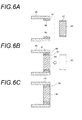
- 6A, 6B and 6C show a procedure for fixing the optical member 83 to the opening hole 81 of the distal end hard portion 45 through a plurality of adhesive layers.
- FIG. 6A shows a state in which a second adhesive layer 89 is formed by applying a paste-like second adhesive material to the inner peripheral surface of the opening hole 81 of the distal end hard portion 45, and heating
- 1 shows a state in which a paste-like first adhesive material is applied to the outer peripheral surface of the optical member 83 and then heated to form a first adhesive layer 87.
- the first adhesive and the second adhesive are heated at 200 to 300 ° C., which is lower than the glass softening point (about 400 ° C.), and held for 30 minutes or more. Sometimes the diluent used as needed is burned off to form the layers 87, 89. Here, the glass may be fired in the layers 87 and 89 by further heating and holding at 450 ° C. or higher.
- the optical member 83 is inserted into the opening hole 81 of the distal end hard portion 45 and combined. Since the first adhesive and the second adhesive are solidified, the layers of each adhesive are joined without being disturbed during insertion. Then, by baking at 450 to 500 ° C. above the glass softening point for 20 minutes or more, the optical member 83 and the hard tip portion 45 are sintered through the adhesive layer 85 as shown in FIG. 6C.
- the interface between the first adhesive layer 87 and the second adhesive layer 89 after sintering actually forms a boundary region of a predetermined width by mutual penetration, and the layers are continuously formed in the boundary region.
- the distribution changes.
- the optical member 83 is sintered to the distal end hard portion 45 using the low melting point glass having a different thermal expansion coefficient for each layer, so that there is no moisture permeability and sufficient heat resistance and durability. A sealed structure is obtained.
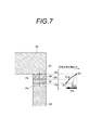
- FIG. 7 is an explanatory diagram showing a distribution of thermal stress generated by a temperature change at the joint between the distal end hard portion 45 and the optical member 83.
- Radial direction of optical member 83 (straight line Pa-Pb direction) in the laminated line of optical member 83, first adhesive material layer 87, second adhesive material layer 89, and hard tip portion 45 indicated by straight line Pa-Pb
- These thermal stresses can be alleviated by the first adhesive layer 87 and the second adhesive layer 89.
- the adhesive layer is composed of a plurality of layers, the generated thermal stress can be reduced as compared with the case where the distal end hard portion 45 and the optical member 83 are joined in a single layer.
- the gap between the distal end hard portion 45 and the optical member 83 required for a medical electronic endoscope is about 0.01 to 0.2 mm, and materials having greatly different thermal expansion coefficients within such a small thickness.
- a material having a thermal expansion coefficient intermediate between the two materials is interposed between the two materials in a single layer, the substantial thermal stress relaxation effect is small.
- the second adhesive layer 89 reduces the thermal stress S2 on the distal end hard portion 45 side to S1a on the opposite side to the distal end hard portion 45 side.
- the layer 87 reduces the thermal stress from S1a to S1.
- the thermal stress value becomes a gentle curve and the stress up to S2a is smaller than the stress relaxation amount ⁇ S from S2 to S1. Stays in mitigation amount.
- one of the facing adhesive layers is cured first.
- the glass of the other layer is cured on one layer of the cured side, and both layers are bonded.
- this other layer hardens, the stress escapes in the direction of the interface and stress relaxation occurs.
- the optical member 83 and the optical member 83 are connected to each other through the low melting point glass adhesive layers 85 having different thermal expansion coefficients.
- the supporting hard tip 45 can be sealed with improved heat resistance and durability. Moreover, since a complicated process is not accompanied, workability is not impaired.
- the optical member 83 can be formed of single crystal sapphire in addition to glass. By forming the optical member 83 with high-strength single crystal sapphire, the thickness of the optical member 83 can be reduced to, for example, about 0.15 mm to 0.3 mm (diameter 1 to 2 mm).
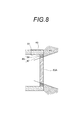
- FIG. 8 is a schematic cross-sectional view in which an optical member made of a sapphire plate 83A is fixed to the opening hole 81 of the hard tip portion 45 via a plurality of adhesive layers 85. Since the sapphire plate 83A can be thinned, the thickness of the plurality of adhesive layers 85 such as the first adhesive layer 87 and the second adhesive layer 89 can also be reduced. When the sapphire plate 83A is an illumination window and illumination light having a large light emitting area and a wide divergence angle is emitted, vignetting 91 is likely to occur at the tip of the illumination window. However, since the adhesive layer 85 is formed thin, the region of the adhesive layer 85 that causes the vignetting 91 is limited to a small range, and heat generation from the region can be minimized.
- a black pigment may be mixed in the first adhesive layer 87.
- An isotropic graphite material is mentioned as a black pigment.
- the isotropic graphite material has a thermal expansion coefficient of 4.4 to 7.1 ⁇ 10 ⁇ 6 ° C. ⁇ 1, which is close to the thermal expansion coefficient of the optical member 83 and can be suitably used.
- the material has been described as stainless steel (SUS304), but a material having a smaller thermal expansion coefficient can be used.
- Examples of the material of the tip hard portion 45 include Kovar (trade name): Kovar (components: Ni 29 wt%, Co 17 wt%, Fe Bal., Thermal expansion coefficient: 4.8 ⁇ 10 ⁇ 6 (30 to 400 ° C. ) ° C.
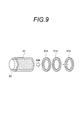
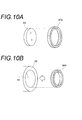
- FIG. 9 is an explanatory view schematically showing how the first adhesive preform is produced.
- a paste-like first adhesive material is applied to the side surface of the columnar rod body 93 and heated to 200 to 300 ° C. lower than the glass softening point.
- the organic binder or diluent contained in the glass paste is burned off, and the first adhesive layer 95 is formed on the side surface of the rod 93.
- the layer 95 is cut into a plurality of annular individuals by slicing perpendicularly to the axis of the rod body 93 with a cutter (not shown). Both sides of each individual are polished to form a preform 87A.
- the preform 87A is inserted into the outer peripheral surface of the optical member 83 and incorporated.
- the first adhesive layer can be formed easily and quickly.
- a second adhesive preform is produced by the same manufacturing method, and the produced preform 89A is inserted into the opening hole 81 of the hard end portion 45 as shown in FIG.
- the adhesive layer can be formed easily and quickly.
- each adhesive layer is formed using a preform
- This sapphire plate is fixed to the hard tip portion.
- An example of a process for fixing the sapphire plate is shown below.
- a first adhesive preform is attached to the outer peripheral surface of the sapphire plate, which is the optical member 83, and temporarily fixed by heating.
- a paste-like second adhesive is applied to the opening hole of the hard tip portion.
- the sapphire plate provided with the first adhesive preform is fitted into the opening hole of the tip hard part. (4) Bake at a temperature above the glass softening point.
- a thin sapphire plate that is difficult to handle can be easily and reliably fixed without causing warping or dropping off.
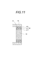
- FIG. 11 is a schematic cross-sectional view in which the optical member 83 is fixed to the opening hole 81 of the distal end hard portion 45 through three layers of adhesive layers.
- a third adhesive material having a thermal expansion coefficient intermediate between the first adhesive material and the second adhesive material is used between the first adhesive layer 87 and the second adhesive layer 89.
- Layer 97 is formed between the first adhesive layer 87 and the second adhesive, and may be a value greater than, for example, the first adhesive and the second adhesive. . That is, the first adhesive, the second adhesive, and the third adhesive need only have different thermal expansion coefficients.
- the third adhesive material includes a low melting point glass frit made of bismuth-based glass as a filler, like the first adhesive material and the second adhesive material described above.
- the bismuth-based glass refers to a glass whose main component is composed of bismuth-based glass.
- the third adhesive is a glass paste containing Bi 2 O 3 —ZnO—B 2 O 3 glass frit, and its thermal expansion coefficient ⁇ 3 is 8.8 ⁇ 10 ⁇ 6 [° C. ⁇ 1 ]. (100 to 300 ° C.).
- a glass paste containing a P 2 O 5 —ZnO—R 2 O glass frit thermal expansion coefficient 12.3 ⁇ 10 ⁇ 6 [° C. ⁇ 1 ]
- the third adhesive can be used as the third adhesive. .
- the above three-layer structure can be formed as follows. First, the third adhesive layer 97 is formed outside the first adhesive layer 87, and then inserted into the opening 81 in which the second adhesive layer 89 of the distal end hard portion 45 is formed. And sinter. Alternatively, the third adhesive layer 97 is formed inside the second adhesive layer 89, and then the optical member 83 in which the first adhesive layer 87 is formed is inserted into the opening 81. Sinter. Alternatively, a third adhesive layer 97 is formed on the outer side of the first adhesive layer 87 and on the inner side of the second adhesive layer 89, and the optical member 83 is inserted into the opening 81. Sinter. Since the sintering process is the same as described above, the description thereof is omitted here.
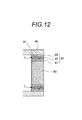
- FIG. 12 shows an adhesive layer subjected to autoclave treatment under conditions of high temperature and high pressure (for example, 134 ° C., pressure 2.2 bar) with respect to an endoscope insertion portion having a sealed structure including an adhesive layer having a three-layer structure shown in FIG. It is a cross-sectional schematic diagram of the front-end
- high temperature and high pressure for example, 134 ° C., pressure 2.2 bar
- the stress applied to the adhesive layer is concentrated on the third adhesive layer 97, the interface between the first adhesive layer 87 and the optical member 83, the first adhesive layer 87 and the third adhesive layer 97.
- Stress applied to the interface with the adhesive layer 97, the interface between the second adhesive layer 89 and the third adhesive layer 97, and the interface between the second adhesive layer 89 and the distal end hard portion 45 Is reduced.
- the crack C as shown in FIG. 12 occurs when the autoclave process is performed up to about 500 to 2000 times, and the crack is generated even when this number of times of autoclave process is performed. About 50% of the number of samples.
- the adhesive layer By forming the adhesive layer into a three-layer structure in this way, the stress is concentrated on the third adhesive material layer 97 in the middle, even under harsh conditions such as autoclaving, so that the third adhesive The occurrence of cracks in each layer other than the material layer 97 and at each interface can be prevented, and the durability of the sealed structure can be further improved.
- the adhesive layer has a structure of three or more layers, there are more interfaces between the materials between the tip hard portion and the optical member than in the two-layer structure. It is usually considered that stress concentrates and cracks are likely to occur.
- the inventor has shown that, by making the adhesive layer into a three-layer structure, the stress concentration at the interface is rather relaxed and the stress can be concentrated on the middle adhesive layer. I found it.
- the gap between the distal end hard portion 45 and the optical member 83 required for a medical electronic endoscope is about 0.01 to 0.2 mm.
- This configuration is particularly useful for a connection structure in which the difference between the thermal expansion coefficients of the distal end hard portion 45 and the optical member 83 is large, and a greater strain is generated during the temperature change process.
- the thin sapphire plate 83A is fixed to the distal end hard portion 45 as shown in FIG. 8, it is difficult to manufacture both with high dimensional accuracy and accurately align them.
- the third adhesive layer 97 having viscosity between the first adhesive layer 87 and the second adhesive layer 89 as in the present configuration, When the optical member 83 is combined, the third adhesive layer 97 absorbs this dimensional error. Therefore, both can be easily combined with high accuracy.
- the thermal stress (thermal strain) generated can be further relaxed by imparting stretchability (extensibility) to the third adhesive material.
- stretchability for example, an aluminum alloy filler (made by Toyo Aluminum) made of aluminum metal powder for filler having a particle size of 1 to 100 ⁇ m, or preferably an electrically insulated alloy metal filler may be mixed into the adhesive.
- a black pigment such as an isotropic graphite material may be mixed.
- the third adhesive layer 97 may be composed of a plurality of layers having different thermal expansion coefficients. That is, the adhesive layer may have a structure of four or more layers. In this case, since stress can be concentrated on layers other than the adhesive layers at both ends, the stress applied to each layer can be dispersed, and further heat resistance and durability can be achieved as compared with the case of three layers. It is possible to improve the performance.
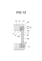
- FIG. 13 is a schematic cross-sectional view in which the optical member 83 is fixed to the stepped portion 111 of the distal end hard portion 45 via a plurality of adhesive layers 85.
- a stepped portion 111 whose diameter is increased by stepping is formed at one end portion of the inner peripheral surface of the opening hole 81 of the distal end hard portion 45.
- an annular side surface 113 facing the opening side of the opening hole 81 and an enlarged inner peripheral surface 115 are formed on the inner peripheral portion where the diameter has been increased.
- the outer peripheral edge portion of the adhesive layer 85 and the optical member 83 is disposed in the region where the opening hole 81 is expanded by the stepped portion 111.
- a first adhesive layer 87 is formed on the entire outer peripheral surface of the optical member 83, and the second adhesive layer 89 is entirely formed on the annular side surface 113 and the enlarged inner peripheral surface 115 of the stepped portion 111. It is formed over the circumference.
- the second adhesive layer 89 is bonded to the first adhesive layer 87 and the outer peripheral edge 83a of the optical member 83 facing the annular side surface 113. That is, the outer peripheral edge portion 83a of the optical member 83 facing the annular side surface 113 is joined to the second adhesive layer 89 over the entire periphery of the outer peripheral edge portion 83a, and the sealed structure of the distal end hard portion 45 and the optical member 83 is sealed. Is forming.
- the outer surface 83b of the optical member 83 is disposed flush with the distal end surface 45a of the distal end hard portion 45, and the optical member 83 is caulked with a locking claw 117 protruding to the distal end hard portion 45 so as to be plastically deformable. , Held in the stepped portion 111.
- the locking claw 117 urges the optical member 83 in the thickness direction by pressure deformation indicated by an arrow K in the drawing.
- the locking claws 117 are provided in at least three positions on the distal end hard portion 45 to prevent the optical member 83 from falling off. By this locking claw 117, the optical member 83 is stably held in the stepped portion 111, and it is easy to fix the optical member 83 to the distal end surface 45a of the distal end hard portion 45 flatly.
- the step of fixing the optical member 83 to the stepped portion 111 of the distal end hard portion 45 is the same as the above-described step, and an example thereof is shown below.
- a paste-like first adhesive is applied to the outer peripheral surface 83c of the optical member 83, and temporarily fixed by heating at a temperature lower than the glass softening point.
- a paste-like second adhesive is applied to the opening hole of the hard tip portion.
- the optical member 83 on which the first adhesive layer 87 is formed is fitted into the stepped portion 111 of the distal end hard portion 45.
- the optical member 83 is supported by the locking claw. (5) Bake at a temperature above the glass softening point.
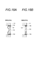
- FIGS. 15A to 15D when a sapphire plate is used as the optical member 83, the steps shown in FIGS. 15A to 15D can be performed.
- a first adhesive preform 87A is attached to the outer peripheral surface 83c of the sapphire plate 83A and temporarily fixed by heating.
- a paste-like second adhesive is applied to the enlarged inner peripheral surface 115 of the distal end hard portion 45.
- the sapphire plate 83A to which the preform 87A is temporarily fixed is fitted into the stepped portion 111 of the distal end hard portion 45.
- the second adhesive material spreads on the annular side surface 113 of the distal end hard portion 45 and the outer peripheral edge portion 83a of the sapphire plate 83A facing the annular side surface 113.
- the optical member 83 is supported by the locking claw.
- the distal end hard portion 45 of the optical member 83 (83A) is composed of the outer peripheral surface 83c and the outer peripheral portion 83a. As a result, the airtightness and durability are improved.
- the adhesive layer has a three-layer structure
- the third adhesive material is formed on the outer peripheral surface of the first adhesive material preform 87A. Attach the preform and temporarily fix it by heating. Then, the steps after FIG. 15B may be performed.
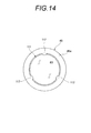
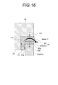
- FIG. 16 is an enlarged explanatory view showing the R portion of FIG. 13 in an enlarged manner.
- the optical member 83 thermal expansion coefficient alpha OP first coefficient of thermal expansion of the thermal expansion coefficient alpha 1 ⁇ second adhesive material of the adhesive alpha 2 (83A) ⁇ Since there is a relationship of the thermal expansion coefficient ⁇ f of the distal end hard portion 45, when the temperature rises, a tensile stress P is generated in the radial direction of the optical member 83 (83A) and at the outer peripheral edge portion 83a of the optical member 83 (83A). Shear stress Q is generated.
- the shear stress Q is generated over the entire circumference of the outer peripheral edge 83a of the optical member 83 (83A), and acts as a bending moment M that tries to warp the optical member 83 (83A) from the outside to the inside of the opening hole 81. .
- the thermal strain accompanying the temperature change is dispersed throughout the adhesive layer 85 and the optical member 83 (83A).
- the total thermal stress energy at this time is the sum of the energy that generates the bending moment M due to the shear stress Q and the energy of the tensile stress P. Therefore, as shown in FIG. Compared to the case where the tensile stress P is relatively reduced, the total thermal stress energy is distributed to the shear stress Q.
- the tensile stress P and the shear stress Q are suppressed to a relatively low stress level due to the dispersion of the total thermal stress energy, and even when the temperature change amount is large, breakage and breakage are less likely to occur.
- sealing performance, heat resistance, chemical resistance, and mechanical durability that can handle autoclave cleaning can be obtained at the same time.
- autoclave washing it is heated to about 160 ° C. to 180 ° C., pressurized to about 2 bar, sterilized and disinfected and cleaned with chemicals.
- the thermal distortion increases as the temperature rises from the start of the cleaning process, and when the set temperature is reached, the amount of thermal deformation from room temperature becomes the maximum. At this time, the thermal stress between the optical member 83 and the hard tip portion 45 is maximized.
- a plurality of adhesive layers such as a first adhesive layer and a second adhesive layer are provided between the optical member 83 and the hard tip 45, and the thermal expansion coefficient of each adhesive layer is As an example, the distribution increases stepwise from the optical member 83 to the hard tip portion 45. For this reason, even if the endoscope is exposed to a high temperature environment such as autoclave cleaning, the generated thermal stress is reduced, and each adhesive layer is broken or damaged, or the optical member 83 or the distal end hard portion 45 is cracked or deformed. Can be prevented.
- the thermal stress described above is not limited to the thermal stress caused by the change in the environmental temperature of the endoscope, but also against the thermal stress generated during the heating and heating in the sintering process of the distal end hard portion 45 and the optical member 83. Can be reduced as well.
- low-melting glass can be composed of bismuth-based glass or silicate-based glass, and additives such as zinc oxide, alumina, diboron trioxide, and silica are added to control the thermal expansion coefficient and the like.
- additives such as zinc oxide, alumina, diboron trioxide, and silica are added to control the thermal expansion coefficient and the like.
- the thermal expansion coefficient can be increased by adding magnesium oxide to the adhesive layer formed on the metal side having a large thermal expansion coefficient.
- the thermal expansion coefficient can be lowered by adding a small amount of tin oxide to the adhesive layer formed on the optical member side.
- the endoscope has been described as an example of the medical device, but the present invention is not limited to a medical endoscope in which an electronic component such as an imaging element is incorporated in the distal end portion, but a rigid endoscope, a scope endoscope, The present invention can also be applied to various medical devices such as various surgical devices.
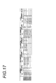
- FIG. 17 shows experimental examples of configuration examples 1 to 6 having a sealed structure of the optical member and the hard tip portion.
- the hard tip portion is stainless steel (SUS410) having a thermal expansion coefficient ⁇ f of 10.0 [ ⁇ 10 ⁇ 6 ° C. ⁇ 1 ], and the optical member has a thermal expansion coefficient ⁇ OP of 4. 5 [ ⁇ 10 ⁇ 6 ° C. ⁇ 1 ] sapphire plate.
- the adhesive layer has a laminated structure of three layers.
- the second adhesive layer is made of a glass paste containing Bi 2 O 3 —ZnO 2 —B 2 O 3 glass frit (thermal expansion coefficient ⁇ 1 : 11.5 [ ⁇ 10 ⁇ 6 ° C. ⁇ 1 ], firing temperature) 450 ° C.) was formed at a temperature below the glass softening point.
- the first adhesive layer is made of a glass paste containing Bi 2 O 3 —ZnO 2 —B 2 O 3 glass frit (thermal expansion coefficient ⁇ 2 : 8.5 [ ⁇ 10 ⁇ 6 ° C. ⁇ 1 ], firing temperature. 450 ° C.) was formed at a temperature below the glass softening point.
- the third adhesive layer is made of a glass paste containing Bi 2 O 3 —ZnO 2 —B 2 O 3 glass frit (thermal expansion coefficient ⁇ 3 : 8.8 [ ⁇ 10 ⁇ 6 C.- 1 ] and a firing temperature of 480.degree. C. were formed by combining the first and second adhesive layers and sintering at a temperature slightly exceeding the firing temperature.
- Configuration example 2 is the same configuration as configuration example 1 except that the hard tip portion is made of stainless steel (SUS304) having a thermal expansion coefficient ⁇ f of 17.3 [ ⁇ 10 ⁇ 6 ° C. ⁇ 1 ].
- the optical member in the configuration example 1 is made of L-LASFN (trade name: manufactured by Sumita Optical Co., Ltd.) glass
- the first adhesive layer has a thermal expansion coefficient ⁇ 2 of 11.5 [ ⁇ 10 ⁇ 6 ° C.- 1 ] and a firing temperature of 450 ° C.
- the second adhesive layer has a thermal expansion coefficient ⁇ 2 of 8.8 [ ⁇ 10 ⁇ 6 ° C. ⁇ 1 ] and a firing temperature of 450 ° C.
- the third adhesive layer is formed of a glass paste containing P 2 O 5 —ZnO—R 2 O glass frit having a thermal expansion coefficient ⁇ 2 of 12.3 [ ⁇ 10 ⁇ 6 ° C. ⁇ 1 ] and a baking temperature of 480 ° C. This is the configuration.
- Configuration example 4 is the same as configuration example 1 except that the hard tip portion is stainless steel (SUS304) with a thermal expansion coefficient ⁇ f of 17.3 [ ⁇ 10 ⁇ 6 ° C. ⁇ 1 ], and the third adhesive layer is omitted. This is the configuration.
- each adhesive layer constituting the adhesive layer was formed by heating to a temperature equal to or lower than the glass softening point, after which both were combined and sintered at a temperature slightly above the firing temperature.
- the tip hard portion is made of stainless steel (SUS410), the optical member is made of L-LASFN17 (trade name: manufactured by Sumita Optical Co., Ltd.), and the second adhesive layer is not provided.
- the first adhesive layer is provided as a single layer.
- the hard tip portion is SUS304 in the configuration example 5
- the first adhesive layer has a thermal expansion coefficient ⁇ 2 of 12.3 [ ⁇ 10 ⁇ 6 ° C. ⁇ 1 ], and a firing temperature of 480 ° C.
- This is a structure formed of a glass paste containing a P 2 O 5 —ZnO—R 2 O glass frit.
- FIG. 17 shows the results of evaluating the adhesive strength of the window (observation window or irradiation window) before and after 500 sterilization treatments for the above structural examples 1 to 6.
- the adhesive strength was evaluated by +++ when the strength change from the initial state was ⁇ 5% (no change was observed), ++ when ⁇ 10%, + when ⁇ 50%, and clouding on the low melting point glass part. The case where a crack or a crack has occurred is marked as-.
- the durability and heat resistance can be improved by making the adhesive material have a two-layer structure.
- the durability and heat resistance can be further improved by forming the adhesive into a three-layer structure.
- the disclosed electronic endoscope apparatus includes an optical member and a distal end of an insertion portion in which a frame body made of a material having a different thermal expansion coefficient from the optical member and holding the optical member is inserted into a subject.
- An electronic endoscope device disposed in a portion, wherein the tip portion incorporates an electronic component including an imaging device, and the optical member and the frame have three or more different thermal expansion coefficients. Are connected via an adhesive layer.
- the three or more adhesive layers are each made of low-melting glass.
- the low melting point glass is made of bismuth glass.
- the three or more adhesive layers are disposed between an outer peripheral surface of the optical member formed in a plate shape and an inner peripheral surface of the frame body facing the outer peripheral surface. At least formed.
- a stepped portion whose diameter is increased by stepping is formed at one end portion of the inner peripheral surface of the frame body, and an annular side surface formed by the stepping of the frame body, Any one of the three or more adhesive layers is provided over the entire circumference, and the outer peripheral edge portion of the optical member facing the annular side surface is bonded to any one of the layers over the entire circumference of the outer peripheral edge portion. It has been done.
- the frame body is made of an Fe-based material containing at least one of Ni and Co.
- the optical member is made of sapphire.
- an optical member and a frame body made of a material having a thermal expansion coefficient different from that of the optical member and holding the optical member are inserted into a subject.
- a method of manufacturing an electronic endoscope apparatus which is disposed at a distal end portion of an insertion portion and includes an electronic component including an image pickup device at the distal end portion, wherein the optical member and the frame are connected to an outer periphery of the optical member.
- Two adhesive layer forming steps, an outer peripheral surface side of the first adhesive layer, and the second adhesive layer A third adhesive layer forming step of forming a third adhesive layer on at least one of the inner peripheral surface side of the first adhesive material layer, the first adhesive material layer forming step, the second adhesive material layer forming step, and the first
- a sintering step of sintering the frame and the optical member is performed at least through an adhesive layer including the adhesive layer.
- each of the adhesives includes a low melting point glass frit as a filler.
- the paste-like first adhesive is applied to the outer peripheral surface of the optical member, and then the glass is fired by heating.
- a step of forming a layer of the first adhesive is
- an inner peripheral surface of a preform formed by annularly forming the first adhesive material is fitted to an outer peripheral surface of the optical member. And the step of forming the first adhesive layer.
- the second adhesive layer forming step includes applying the paste-like second adhesive material to the inner peripheral surface of the frame body, and then baking the glass by heating. A step of forming a layer of the second adhesive material.
- an outer peripheral surface of a preform formed by annularly forming the second adhesive material is fitted to an inner peripheral surface of the frame body.
- a step of forming a layer of the second adhesive material is provided.
- the step of forming the second adhesive layer is provided with a stepped portion whose diameter is increased by stepping at one end of the inner peripheral surface of the frame.
- the second adhesive layer is formed on the expanded inner peripheral surface of the expanded portion
- the third adhesive layer forming step includes a third adhesive layer on the outer side of the first adhesive layer.
- the outer peripheral surface of the optical member is transferred to a second adhesive layer formed on the enlarged inner peripheral surface of the stepped portion.
- the layer of the second adhesive material extends to the annular side surface formed by the step of the frame, and the outer surface of the optical member faces the outer surface.
- thermoelectric endoscope apparatus According to the electronic endoscope apparatus of the present invention, heat resistance and durability under severe conditions such as autoclave treatment can be improved.
Landscapes
- Physics & Mathematics (AREA)
- Health & Medical Sciences (AREA)
- Life Sciences & Earth Sciences (AREA)
- Optics & Photonics (AREA)
- Surgery (AREA)
- Engineering & Computer Science (AREA)
- General Physics & Mathematics (AREA)
- Astronomy & Astrophysics (AREA)
- Biophysics (AREA)
- Animal Behavior & Ethology (AREA)
- Pathology (AREA)
- Biomedical Technology (AREA)
- Heart & Thoracic Surgery (AREA)
- Medical Informatics (AREA)
- Molecular Biology (AREA)
- Radiology & Medical Imaging (AREA)
- General Health & Medical Sciences (AREA)
- Public Health (AREA)
- Veterinary Medicine (AREA)
- Nuclear Medicine, Radiotherapy & Molecular Imaging (AREA)
- Manufacturing & Machinery (AREA)
- Endoscopes (AREA)
- Instruments For Viewing The Inside Of Hollow Bodies (AREA)
Abstract
L'invention concerne un dispositif d'endoscope électronique qui présente une tolérance améliorée à la chaleur et une durabilité améliorée. Dans ledit dispositif d'endoscope électronique, un élément optique (83) et un cadre (45) qui maintient ledit élément optique (83) et comprend un matériau ayant un coefficient de dilatation thermique différent de celui de l'élément optique (83) sont disposés dans une partie d'introduction qui est introduite dans un sujet. L'élément optique (83) et le cadre (45) sont reliés par trois couches adhésives feuilletées (85) ayant des coefficients de dilatation thermique différents les uns des autres.
Priority Applications (3)
| Application Number | Priority Date | Filing Date | Title |
|---|---|---|---|
| EP12796747.9A EP2719315A4 (fr) | 2011-06-07 | 2012-06-05 | Dispositif d'endoscope électronique et son procédé de fabrication |
| CN201280024352.XA CN103547206A (zh) | 2011-06-07 | 2012-06-05 | 电子内窥镜装置及其制造方法 |
| US14/067,637 US20140058201A1 (en) | 2011-06-07 | 2013-10-30 | Electronic endoscope device and manufacturing method thereof |
Applications Claiming Priority (4)
| Application Number | Priority Date | Filing Date | Title |
|---|---|---|---|
| JP2011127482 | 2011-06-07 | ||
| JP2011-127482 | 2011-06-07 | ||
| JP2012113425A JP5746997B2 (ja) | 2011-06-07 | 2012-05-17 | 電子内視鏡装置の製造方法 |
| JP2012-113425 | 2012-05-17 |
Related Child Applications (1)
| Application Number | Title | Priority Date | Filing Date |
|---|---|---|---|
| US14/067,637 Continuation US20140058201A1 (en) | 2011-06-07 | 2013-10-30 | Electronic endoscope device and manufacturing method thereof |
Publications (1)
| Publication Number | Publication Date |
|---|---|
| WO2012169476A1 true WO2012169476A1 (fr) | 2012-12-13 |
Family
ID=47296039
Family Applications (1)
| Application Number | Title | Priority Date | Filing Date |
|---|---|---|---|
| PCT/JP2012/064419 Ceased WO2012169476A1 (fr) | 2011-06-07 | 2012-06-05 | Dispositif d'endoscope électronique et son procédé de fabrication |
Country Status (5)
| Country | Link |
|---|---|
| US (1) | US20140058201A1 (fr) |
| EP (1) | EP2719315A4 (fr) |
| JP (1) | JP5746997B2 (fr) |
| CN (1) | CN103547206A (fr) |
| WO (1) | WO2012169476A1 (fr) |
Cited By (1)
| Publication number | Priority date | Publication date | Assignee | Title |
|---|---|---|---|---|
| WO2016194074A1 (fr) * | 2015-05-29 | 2016-12-08 | オリンパス株式会社 | Dispositif d'imagerie, système d'endoscope, et procédé de fabrication de dispositif d'imagerie |
Families Citing this family (13)
| Publication number | Priority date | Publication date | Assignee | Title |
|---|---|---|---|---|
| US9105561B2 (en) * | 2012-05-14 | 2015-08-11 | The Boeing Company | Layered bonded structures formed from reactive bonding of zinc metal and zinc peroxide |
| DE102013202539B3 (de) * | 2013-02-18 | 2014-04-24 | Olympus Winter & Ibe Gmbh | Verfahren zum Herstellen eines Endoskops und Endoskop |
| US9186048B2 (en) * | 2013-04-04 | 2015-11-17 | General Electric Company | Hermetically sealed boroscope probe tip |
| DE102013217500A1 (de) * | 2013-09-03 | 2015-03-05 | Olympus Winter & Ibe Gmbh | Endoskop und Endoskopspitze |
| DE102014012569A1 (de) * | 2014-08-29 | 2016-03-03 | Olympus Winter & Ibe Gmbh | Medizinisches Endoskop mit einem Deckglas aus Saphir |
| KR101771796B1 (ko) | 2015-08-10 | 2017-08-25 | 삼성전기주식회사 | 렌즈 |
| CN107922248B (zh) * | 2015-09-25 | 2020-09-04 | 株式会社日立制作所 | 接合材料及使用该接合材料的接合体 |
| JP6214834B2 (ja) * | 2015-11-09 | 2017-10-18 | オリンパス株式会社 | 内視鏡 |
| JP6486866B2 (ja) * | 2016-05-27 | 2019-03-20 | 日立オートモティブシステムズ株式会社 | 物理量測定装置およびその製造方法ならびに物理量測定素子 |
| JPWO2017212520A1 (ja) * | 2016-06-06 | 2019-04-04 | オリンパス株式会社 | 内視鏡用光学ユニットの製造方法、内視鏡用光学ユニット、および内視鏡 |
| JP6850200B2 (ja) * | 2017-05-31 | 2021-03-31 | 富士フイルム株式会社 | 内視鏡及び内視鏡装置 |
| WO2019230072A1 (fr) | 2018-05-31 | 2019-12-05 | オリンパス株式会社 | Endoscope |
| WO2019230071A1 (fr) * | 2018-05-31 | 2019-12-05 | オリンパス株式会社 | Endoscope |
Citations (4)
| Publication number | Priority date | Publication date | Assignee | Title |
|---|---|---|---|---|
| JPS6132017A (ja) * | 1984-07-23 | 1986-02-14 | Olympus Optical Co Ltd | レンズ保持装置 |
| JPS61119118U (fr) * | 1985-01-10 | 1986-07-28 | ||
| JP2005227728A (ja) | 2004-02-16 | 2005-08-25 | Pentax Corp | レンズ接合体の製造方法、レンズ接合体および内視鏡 |
| JP2005234239A (ja) * | 2004-02-19 | 2005-09-02 | Pentax Corp | レンズ接合体の製造方法、レンズ接合体および内視鏡 |
Family Cites Families (8)
| Publication number | Priority date | Publication date | Assignee | Title |
|---|---|---|---|---|
| US2517019A (en) * | 1948-09-24 | 1950-08-01 | Corning Glass Works | Graded seal |
| JPH02281201A (ja) * | 1989-04-24 | 1990-11-16 | Nec Corp | 集束性ロッドレンズの固定構造 |
| JP2004000681A (ja) * | 1998-08-07 | 2004-01-08 | Olympus Corp | 内視鏡 |
| JP3836401B2 (ja) * | 2002-05-30 | 2006-10-25 | アンリツ株式会社 | 光学装置 |
| JP2006022249A (ja) * | 2004-07-09 | 2006-01-26 | Ricoh Co Ltd | 接着接合構造、接合方法および接合装置 |
| JP4343890B2 (ja) * | 2005-09-29 | 2009-10-14 | オリンパスメディカルシステムズ株式会社 | 電子内視鏡 |
| US20080160274A1 (en) * | 2006-12-31 | 2008-07-03 | Chi Hung Dang | Coefficient of thermal expansion adaptor |
| JP5366722B2 (ja) * | 2009-09-01 | 2013-12-11 | Hoya株式会社 | 内視鏡 |
-
2012
- 2012-05-17 JP JP2012113425A patent/JP5746997B2/ja not_active Expired - Fee Related
- 2012-06-05 CN CN201280024352.XA patent/CN103547206A/zh active Pending
- 2012-06-05 WO PCT/JP2012/064419 patent/WO2012169476A1/fr not_active Ceased
- 2012-06-05 EP EP12796747.9A patent/EP2719315A4/fr not_active Withdrawn
-
2013
- 2013-10-30 US US14/067,637 patent/US20140058201A1/en not_active Abandoned
Patent Citations (4)
| Publication number | Priority date | Publication date | Assignee | Title |
|---|---|---|---|---|
| JPS6132017A (ja) * | 1984-07-23 | 1986-02-14 | Olympus Optical Co Ltd | レンズ保持装置 |
| JPS61119118U (fr) * | 1985-01-10 | 1986-07-28 | ||
| JP2005227728A (ja) | 2004-02-16 | 2005-08-25 | Pentax Corp | レンズ接合体の製造方法、レンズ接合体および内視鏡 |
| JP2005234239A (ja) * | 2004-02-19 | 2005-09-02 | Pentax Corp | レンズ接合体の製造方法、レンズ接合体および内視鏡 |
Non-Patent Citations (1)
| Title |
|---|
| See also references of EP2719315A4 * |
Cited By (3)
| Publication number | Priority date | Publication date | Assignee | Title |
|---|---|---|---|---|
| WO2016194074A1 (fr) * | 2015-05-29 | 2016-12-08 | オリンパス株式会社 | Dispositif d'imagerie, système d'endoscope, et procédé de fabrication de dispositif d'imagerie |
| CN107613838A (zh) * | 2015-05-29 | 2018-01-19 | 奥林巴斯株式会社 | 摄像装置、内窥镜系统以及摄像装置的制造方法 |
| JPWO2016194074A1 (ja) * | 2015-05-29 | 2018-05-24 | オリンパス株式会社 | 撮像装置、内視鏡システムおよび撮像装置の製造方法 |
Also Published As
| Publication number | Publication date |
|---|---|
| US20140058201A1 (en) | 2014-02-27 |
| JP5746997B2 (ja) | 2015-07-08 |
| JP2013013712A (ja) | 2013-01-24 |
| CN103547206A (zh) | 2014-01-29 |
| EP2719315A4 (fr) | 2014-11-05 |
| EP2719315A1 (fr) | 2014-04-16 |
Similar Documents
| Publication | Publication Date | Title |
|---|---|---|
| JP5746997B2 (ja) | 電子内視鏡装置の製造方法 | |
| CN111031884B (zh) | 内窥镜 | |
| USRE43281E1 (en) | Endoscope capable of being autoclaved | |
| US6282349B1 (en) | Launch fiber termination | |
| JP6326561B1 (ja) | 内視鏡、内視鏡の製造方法 | |
| US9380929B2 (en) | Endoscope with an optical member, a frame portion and a bonding member soldering the optical member to the frame portion | |
| JP2008522790A (ja) | 密閉封止型内視鏡アセンブリ | |
| US10254535B2 (en) | Illumination system comprising heterogeneous fiber arrangement | |
| WO2020152782A1 (fr) | Procédé de fabrication de dispositif d'imagerie d'endoscope, dispositif d'imagerie d'endoscope et endoscope | |
| JP6006458B1 (ja) | 内視鏡用撮像ユニット | |
| JP2000107120A (ja) | 内視鏡 | |
| JP6461816B2 (ja) | 撮像装置および内視鏡装置 | |
| WO2014057774A1 (fr) | Endoscope | |
| JP2002085326A (ja) | 内視鏡 | |
| WO2011145466A1 (fr) | Collimateur optique et connecteur optique utilisant ledit collimateur | |
| JP3811335B2 (ja) | 内視鏡 | |
| JP2000139819A (ja) | 内視鏡 | |
| JP2000287913A (ja) | 内視鏡装置 | |
| JP2005227728A (ja) | レンズ接合体の製造方法、レンズ接合体および内視鏡 | |
| US20200060534A1 (en) | Endoscope | |
| WO2020008618A1 (fr) | Dispositif d'imagerie endoscopique et endoscope | |
| JP6526369B2 (ja) | 光源装置 | |
| JP3780177B2 (ja) | 電子内視鏡および電子内視鏡の組み付け方法 | |
| JP2000051142A (ja) | 内視鏡 | |
| US12607801B1 (en) | Assembly device for a light guide |
Legal Events
| Date | Code | Title | Description |
|---|---|---|---|
| 121 | Ep: the epo has been informed by wipo that ep was designated in this application |
Ref document number: 12796747 Country of ref document: EP Kind code of ref document: A1 |
|
| WWE | Wipo information: entry into national phase |
Ref document number: 2012796747 Country of ref document: EP |
|
| NENP | Non-entry into the national phase |
Ref country code: DE |