WO2012169577A1 - 浄水カートリッジおよび浄水器 - Google Patents
浄水カートリッジおよび浄水器 Download PDFInfo
- Publication number
- WO2012169577A1 WO2012169577A1 PCT/JP2012/064657 JP2012064657W WO2012169577A1 WO 2012169577 A1 WO2012169577 A1 WO 2012169577A1 JP 2012064657 W JP2012064657 W JP 2012064657W WO 2012169577 A1 WO2012169577 A1 WO 2012169577A1
- Authority
- WO
- WIPO (PCT)
- Prior art keywords
- water
- opening
- water purification
- purification cartridge
- container
- Prior art date
- Legal status (The legal status is an assumption and is not a legal conclusion. Google has not performed a legal analysis and makes no representation as to the accuracy of the status listed.)
- Ceased
Links
Images





Classifications
-
- C—CHEMISTRY; METALLURGY
- C02—TREATMENT OF WATER, WASTE WATER, SEWAGE, OR SLUDGE
- C02F—TREATMENT OF WATER, WASTE WATER, SEWAGE, OR SLUDGE
- C02F1/00—Treatment of water, waste water, or sewage
- C02F1/001—Processes for the treatment of water whereby the filtration technique is of importance
- C02F1/003—Processes for the treatment of water whereby the filtration technique is of importance using household-type filters for producing potable water, e.g. pitchers, bottles, faucet mounted devices
-
- B—PERFORMING OPERATIONS; TRANSPORTING
- B01—PHYSICAL OR CHEMICAL PROCESSES OR APPARATUS IN GENERAL
- B01D—SEPARATION
- B01D63/00—Apparatus in general for separation processes using semi-permeable membranes
- B01D63/02—Hollow fibre modules
- B01D63/024—Hollow fibre modules with a single potted end
- B01D63/0241—Hollow fibre modules with a single potted end being U-shaped
-
- B—PERFORMING OPERATIONS; TRANSPORTING
- B01—PHYSICAL OR CHEMICAL PROCESSES OR APPARATUS IN GENERAL
- B01D—SEPARATION
- B01D2311/00—Details relating to membrane separation process operations and control
- B01D2311/26—Further operations combined with membrane separation processes
- B01D2311/2626—Absorption or adsorption
-
- B—PERFORMING OPERATIONS; TRANSPORTING
- B01—PHYSICAL OR CHEMICAL PROCESSES OR APPARATUS IN GENERAL
- B01D—SEPARATION
- B01D2313/00—Details relating to membrane modules or apparatus
- B01D2313/40—Adsorbents within the flow path
-
- B—PERFORMING OPERATIONS; TRANSPORTING
- B01—PHYSICAL OR CHEMICAL PROCESSES OR APPARATUS IN GENERAL
- B01D—SEPARATION
- B01D2313/00—Details relating to membrane modules or apparatus
- B01D2313/44—Cartridge types
-
- C—CHEMISTRY; METALLURGY
- C02—TREATMENT OF WATER, WASTE WATER, SEWAGE, OR SLUDGE
- C02F—TREATMENT OF WATER, WASTE WATER, SEWAGE, OR SLUDGE
- C02F1/00—Treatment of water, waste water, or sewage
- C02F1/28—Treatment of water, waste water, or sewage by sorption
- C02F1/281—Treatment of water, waste water, or sewage by sorption using inorganic sorbents
-
- C—CHEMISTRY; METALLURGY
- C02—TREATMENT OF WATER, WASTE WATER, SEWAGE, OR SLUDGE
- C02F—TREATMENT OF WATER, WASTE WATER, SEWAGE, OR SLUDGE
- C02F1/00—Treatment of water, waste water, or sewage
- C02F1/28—Treatment of water, waste water, or sewage by sorption
- C02F1/283—Treatment of water, waste water, or sewage by sorption using coal, charred products, or inorganic mixtures containing them
-
- C—CHEMISTRY; METALLURGY
- C02—TREATMENT OF WATER, WASTE WATER, SEWAGE, OR SLUDGE
- C02F—TREATMENT OF WATER, WASTE WATER, SEWAGE, OR SLUDGE
- C02F1/00—Treatment of water, waste water, or sewage
- C02F1/28—Treatment of water, waste water, or sewage by sorption
- C02F1/285—Treatment of water, waste water, or sewage by sorption using synthetic organic sorbents
-
- C—CHEMISTRY; METALLURGY
- C02—TREATMENT OF WATER, WASTE WATER, SEWAGE, OR SLUDGE
- C02F—TREATMENT OF WATER, WASTE WATER, SEWAGE, OR SLUDGE
- C02F1/00—Treatment of water, waste water, or sewage
- C02F1/42—Treatment of water, waste water, or sewage by ion-exchange
-
- C—CHEMISTRY; METALLURGY
- C02—TREATMENT OF WATER, WASTE WATER, SEWAGE, OR SLUDGE
- C02F—TREATMENT OF WATER, WASTE WATER, SEWAGE, OR SLUDGE
- C02F1/00—Treatment of water, waste water, or sewage
- C02F1/44—Treatment of water, waste water, or sewage by dialysis, osmosis or reverse osmosis
- C02F1/444—Treatment of water, waste water, or sewage by dialysis, osmosis or reverse osmosis by ultrafiltration or microfiltration
-
- C—CHEMISTRY; METALLURGY
- C02—TREATMENT OF WATER, WASTE WATER, SEWAGE, OR SLUDGE
- C02F—TREATMENT OF WATER, WASTE WATER, SEWAGE, OR SLUDGE
- C02F1/00—Treatment of water, waste water, or sewage
- C02F1/42—Treatment of water, waste water, or sewage by ion-exchange
- C02F2001/425—Treatment of water, waste water, or sewage by ion-exchange using cation exchangers
-
- C—CHEMISTRY; METALLURGY
- C02—TREATMENT OF WATER, WASTE WATER, SEWAGE, OR SLUDGE
- C02F—TREATMENT OF WATER, WASTE WATER, SEWAGE, OR SLUDGE
- C02F2101/00—Nature of the contaminant
- C02F2101/10—Inorganic compounds
- C02F2101/12—Halogens or halogen-containing compounds
-
- C—CHEMISTRY; METALLURGY
- C02—TREATMENT OF WATER, WASTE WATER, SEWAGE, OR SLUDGE
- C02F—TREATMENT OF WATER, WASTE WATER, SEWAGE, OR SLUDGE
- C02F2101/00—Nature of the contaminant
- C02F2101/10—Inorganic compounds
- C02F2101/20—Heavy metals or heavy metal compounds
-
- C—CHEMISTRY; METALLURGY
- C02—TREATMENT OF WATER, WASTE WATER, SEWAGE, OR SLUDGE
- C02F—TREATMENT OF WATER, WASTE WATER, SEWAGE, OR SLUDGE
- C02F2101/00—Nature of the contaminant
- C02F2101/30—Organic compounds
- C02F2101/36—Organic compounds containing halogen
-
- C—CHEMISTRY; METALLURGY
- C02—TREATMENT OF WATER, WASTE WATER, SEWAGE, OR SLUDGE
- C02F—TREATMENT OF WATER, WASTE WATER, SEWAGE, OR SLUDGE
- C02F2201/00—Apparatus for treatment of water, waste water or sewage
- C02F2201/002—Construction details of the apparatus
- C02F2201/004—Seals, connections
-
- C—CHEMISTRY; METALLURGY
- C02—TREATMENT OF WATER, WASTE WATER, SEWAGE, OR SLUDGE
- C02F—TREATMENT OF WATER, WASTE WATER, SEWAGE, OR SLUDGE
- C02F2201/00—Apparatus for treatment of water, waste water or sewage
- C02F2201/002—Construction details of the apparatus
- C02F2201/006—Cartridges
-
- C—CHEMISTRY; METALLURGY
- C02—TREATMENT OF WATER, WASTE WATER, SEWAGE, OR SLUDGE
- C02F—TREATMENT OF WATER, WASTE WATER, SEWAGE, OR SLUDGE
- C02F2307/00—Location of water treatment or water treatment device
- C02F2307/04—Location of water treatment or water treatment device as part of a pitcher or jug
-
- C—CHEMISTRY; METALLURGY
- C02—TREATMENT OF WATER, WASTE WATER, SEWAGE, OR SLUDGE
- C02F—TREATMENT OF WATER, WASTE WATER, SEWAGE, OR SLUDGE
- C02F2307/00—Location of water treatment or water treatment device
- C02F2307/06—Mounted on or being part of a faucet, shower handle or showerhead
Definitions
- the present invention relates to a water purification cartridge.
- the present invention also relates to a water purifier equipped with the water purification cartridge.
- a pot-type water purifier As a water purifier equipped with a water purification cartridge, for example, a pot-type water purifier is known.
- This pot-type water purifier has a structure in which a water purification cartridge is interposed between a raw water storage part located on the upper side and a purified water storage part located on the lower side. The raw water stored in the raw water storage part flows into the purified water storage part through the water purification cartridge by its own weight, and is purified in the water purification cartridge.
- a water purification cartridge with which a pot type water purifier is mounted for example, one described in Patent Document 1 can be cited. In such a water purification cartridge, an ion exchange resin is used as a filter medium.
- an adsorbent such as a chelate resin or an ion exchange resin is used to remove heavy metals such as lead contained in tap water.
- a hollow fiber membrane is also used, and the hollow fiber membrane is generally disposed on the downstream side of the adsorbent.
- the state of heavy metals contained in tap water differs in countries and regions, and conventional water purification cartridges using adsorbents that change the pH of water such as ion exchange resins cannot sufficiently remove heavy metals.
- adsorbents that change the pH of water such as ion exchange resins cannot sufficiently remove heavy metals.
- the pH of tap water is around 8
- a large amount of lead contained in tap water exists in a particle state rather than an ionic state.
- the particulate lead entering the container from the raw water inlet is difficult to be adsorbed by the adsorbent, and therefore flows downstream of the adsorption layer.
- the pH of water changes with an ion exchange resin etc. in the downstream of an adsorption layer, and it tends to be acidic.
- lead is present in an ionic state more than the particulate matter. Therefore, lead may be in an ionic state on the downstream side of the adsorption layer and may pass through the hollow fiber membrane.
- an object of the present invention is to provide a water purification cartridge capable of effectively removing heavy metals contained in raw water even when the water quality is different.
- the present invention has a first opening and a second opening, any one of the first opening and the second opening can be used as a raw water inlet,
- the water purification cartridge according to the present invention can select the direction to be attached to the water source according to the water quality situation, it can efficiently remove heavy metals contained in the raw water regardless of the water quality in the country or region. .
- the water purification cartridge of the present invention has a first opening and a second opening, and any one of the first opening and the second opening can be used as a raw water inlet. And a container having a structure in which the other can be used as a purified water discharge port. Moreover, the water purification cartridge of this invention equips the said container with the filter medium containing the adsorbent which can adsorb
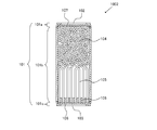
- FIG. 1 is a schematic cross-sectional view for explaining a structural example of a self-weight filtration type water purification cartridge according to an embodiment of the present invention.
- a water purification cartridge 1001 includes a container 101 that houses a filter medium 104 and a hollow fiber membrane 105 therein.
- the filter medium 104 includes an adsorbent that can adsorb heavy metals.
- the container 101 is disposed at a cylindrical case body 101b that accommodates the filter medium 104 and the hollow fiber membrane 105, a first lid 101a disposed at one end of the case 101b, and the other end of the case body 101b.
- the second lid 101c is mainly configured.
- a first opening 102 is provided at the center of the first lid 101a, and a second opening 103 is also provided at the center of the second lid 101c.
- the filter medium 104 and the hollow fiber membrane 105 are disposed in the container 101 in order from the first opening 102 toward the second opening.
- the hollow fiber membrane 105 is fixed in the container using a potting resin 106 at the end of the case body 102b on the second lid 103 side.
- the end portion of the hollow fiber membrane 105 is open on the surface side opposite to the surface on which the hollow fiber membrane of the potting resin 106 is disposed. Water can enter and exit from the opening of the hollow fiber membrane.
- the filter medium 104 is accommodated in the container by a partition wall 107 through which water can pass.
- connection between the first lid 101a and the case body 101b, and the second lid 101c and the case body 101b for example, bonding or welding can be used.
- any one of the first opening 102 and the second opening 103 can function as both a raw water inlet for taking raw water into the container and a purified water outlet for sending purified water to the outside of the container.
- the first opening 102 functions as a raw water inlet
- the second opening 103 functions as a purified water discharge port
- the first opening 102 Functions as a water purification outlet.
- FIG. 2 shows a configuration example of a water purifier including the water purification cartridge 1001 shown in FIG.
- the water purification cartridge 1001 is disposed in the housing portion 202b with the first opening 102 facing upward.
- the vertical direction of the water purification cartridge in this specification represents the direction in the state arrange
- the water purifier 200 is supplied with raw water such as tap water and stored therein, a water purification cartridge 1001 attached to the bottom of the raw water storage unit 204, and below the raw water storage unit 204 and the water purification cartridge 1001. It forms a main body with the clean water storage part 203 located.
- the raw water stored in the raw water storage unit 204 is purified when passing through the water purification cartridge 1001 by its own weight, and flows down to the purified water storage unit 203.
- the water purifier 200 includes a bottomed cylindrical outer container 201 having an open upper end, and a bottomed cylindrical inner container 202 having an open upper end that is inserted from the upper end opening of the outer container 201 and disposed in the outer container 201. It has.
- the inner container 202 is arranged at a depth of about half or less than the outer container 201, and the contents of the inner container 202 are fitted to the upper half of the outer container 201 without any gaps except for the predetermined gap 205.
- the raw water storage unit 204 is formed in the vessel 202.
- a purified water storage unit 203 is provided between the bottom wall 202 a of the inner container 202 and the bottom wall 201 a of the outer container 201.
- the gap 205 is formed so as to extend upward from the purified water storage unit 203 and functions as a pouring path when the purified water is poured.
- An upper lid portion 206 is fitted into the upper end opening of the inner container 202.
- the upper lid 206 may be provided with an openable / closable flap that opens a water supply port at the center and closes the water supply port from above.
- An opening formed at the upper end of the gap 205 functions as a pouring spout, and a pouring lid 207 is provided at the pouring spout.
- the bottom wall 202a of the inner container is provided with a housing portion 202b for housing the water purification cartridge, and the bottom wall 202a of the inner container is formed with a gentle downward slope toward the housing portion 202b.
- the water purification cartridge housing portion 202b is recessed in the bottom wall 202a of the inner container toward the water purification storage portion.
- the water purification cartridge 1001 is fitted into the housing portion 202b from above.
- the center of the bottom of the storage unit 202b is opened, and the raw water storage unit 204 and the purified water located below the storage unit 202b and the opening of the bottom, that is, through the water purification cartridge 1001 attached to the storage unit 202b.
- the storage unit 203 communicates with the storage unit 203.
- the water purification cartridge 1001 can be attached to the storage unit 202b by using a screw-in type or a ratchet type in addition to the insertion type using rubber packing, and is not particularly limited.
- the water purification cartridge 1001 is disposed in the housing portion 202b with the first opening 102 facing upward.
- the 1st opening part 102 functions as a raw
- the 2nd opening part 103 functions as a purified water discharge port.
- the raw water in the raw water storage unit 204 enters the container from the first opening 102 by its own weight.
- the water filtered by the filter medium 104 is further filtered by the hollow fiber membrane 105 and flows out from the end opening of the hollow fiber membrane.
- the obtained purified water is discharged
- the pH of tap water when the pH of tap water is less than 8, lead contained in tap water tends to exist in an ionic state rather than a particulate state. Since lead in an ionic state is easily adsorbed by the filter medium, as shown in FIG. 2, it is better to arrange the first opening 102 upward so that the raw water flows through the filter medium before the hollow fiber membrane. Lead can be removed efficiently.
- the pH of tap water is greater than 8, the lead contained in the tap water tends to exist in a particulate state. In this case, as shown in FIG. 3, the lead can be more efficiently removed by arranging the second opening 103 upward and removing lead with a hollow fiber membrane before the filter medium.
- the 2nd opening part 103 functions as a raw
- the water purification cartridge according to the present invention can efficiently remove heavy metals contained in the raw water by selecting the arrangement direction according to the state of the raw water.
- the filter medium in the present invention includes an adsorbent capable of adsorbing heavy metals (hereinafter abbreviated as heavy metal adsorbent).
- the heavy metal adsorbent is not particularly limited as long as it can adsorb heavy metals, but for example, an ion exchange resin or a chelate resin can be used.
- An ion exchange resin is a kind of synthetic resin and has a structure that ionizes as an ion exchange group in a part of its molecular structure.
- Ion exchange resins are classified into cation exchange resins and anion exchange resins according to the nature of the ion exchange groups.
- cation exchange resins are classified into H type, Na type, K type, etc., depending on the type of ion exchange group. It is done.
- H-type cation exchange resin among the ion exchange resins.
- Examples of ion exchange groups possessed by the H-type cation exchange resin include sulfonic acid groups and (meth) acrylic acid groups.
- a cation exchange resin having a (meth) acrylic acid group is generally called a weakly acidic cation exchange resin.
- the ion exchange resin is a synthetic resin having a functional group (exchange group) for performing ion exchange on the resin matrix, and can exchange ions held in the resin with ions in the solution.
- Ion exchange resins are roughly classified into four types, namely, strongly acidic cation exchange resins, weakly acidic cation exchange resins, strongly basic anion exchange resins, and weakly basic anion exchange resins.
- the chelate resin is a resin in which a functional group that mainly forms a chelate (complex) with a metal ion is introduced, and a specific metal ion can be captured by forming a chelate.
- the chelate resin generally has a chelate-forming group containing two or more electron donating elements such as N, S, O, and P, and can be classified into iminodiacetic acid type, polyamine type, glucamine type, and the like depending on the combination structure. .
- an iminodiacetic acid type chelate resin is preferable from the viewpoint of efficiently removing heavy metals.
- the ion exchange resin and the chelate resin are classified into gel type, porous type, high porous type, MR (macro-reticular) type and the like according to their properties.
- the gel type resin has only micropores formed by a three-dimensional structure of styrene and divinylbenzene (DVB).
- High porous type resins and MR type resins have macropores in addition to micropores.
- High porous resins and MR resins generally have a high degree of crosslinking.
- the porous type is located between the gel type and the high porous type.
- the H-type cation exchange resin and chelate resin used in the present invention are preferably a high porous type or an MR type, and more preferably an MR type.
- the filter medium may include an adsorbent other than the heavy metal adsorbent.
- adsorbents include natural product-based adsorbents (natural zeolite, silver zeolite, acidic clay, etc.), or synthetic-based adsorbents (synthetic zeolite, bacterial adsorption polymer, phosphate ore, molecular sieve, silica gel, silica, etc.
- inorganic adsorbents such as alumina gel and porous glass. Examples of such an adsorbent include a powder adsorbent, a granular adsorbent obtained by granulating the powder adsorbent, or a fibrous adsorbent.
- activated carbon as the adsorbent.
- activated carbon include powdered activated carbon, granular activated carbon, fibrous activated carbon, block activated carbon, extruded activated carbon, molded activated carbon, synthetic granular activated carbon, and synthetic activated carbon.
- fibrous activated carbon examples include fibrous activated carbon.
- a dechlorinating agent excellent in removing residual chlorine can be preferably used.
- the dechlorinating agent calcium sulfite and sodium ascorbate that can maintain the effect of removing chlorine for a long time are preferable.
- the filter medium can contain, for example, 10% by volume or more of heavy metal adsorbent with respect to the entire filter medium, preferably 20% by volume or more, more preferably 30% by volume or more, and more preferably 40% by volume or more. preferable.
- an adsorbent can be used by 1 type or in combination of 2 or more types.
- the hollow fiber membrane in the present invention is not particularly limited, and examples thereof include cellulose-based, polyolefin (polyethylene, polypropylene) -based, polyvinyl alcohol-based, ethylene-vinyl alcohol copolymer, polyether-based, polymethacrylic acid.
- examples include those made of various materials such as methyl (PMMA), polysulfone, polyacrylonitrile, polytetrafluoroethylene (Teflon (registered trademark)), polycarbonate, polyester, polyamide, and aromatic polyamide. It is done.
- polyolefin-based hollow fiber membranes such as polyethylene and polypropylene are preferred.
- the hollow fiber membrane preferably has an outer diameter of 20 to 2000 ⁇ m, a pore diameter of 0.01 to 1 ⁇ m, a porosity of 20 to 90%, and a film thickness of 5 to 300 ⁇ m.
- the hollow fiber membrane is desirably a so-called hydrophilic hollow fiber membrane having a hydrophilic group on the surface.
- the shape of the side surface of the container is not particularly limited, but may be a substantially cylindrical shape, for example.
- the shape of the opening surface of the first opening and the second opening is not particularly limited, but can be, for example, a circular shape, an elliptical shape, or a polygonal shape, and may be an indefinite shape.
- the first opening and the second opening are not particularly limited, but preferably have the same shape. In particular, if the respective members constituting the first opening and the second opening have the same shape, they can be easily arranged in the accommodating portion in any direction.
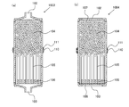
- FIG. 4 is a schematic cross-sectional view showing a preferred configuration example of the present embodiment.
- the shape of the container is substantially cylindrical including the first lid 101a and the second lid 101c.
- a first opening 102 is provided on the upper surface of the substantially cylindrical container, and a partition wall 107 having water permeability for storing the filter medium 104 in the container is provided immediately below the first opening 102.
- the hollow fiber membrane 105 is accommodated in the container by a potting resin 106.
- a second opening 102 is provided on the lower surface of the substantially cylindrical container.
- a filter 108 is provided between the second opening 102 and the potting resin 106.
- FIG. 5 is a schematic cross-sectional view showing a state in which the water purification cartridge 1002 shown in FIG. 4 is disposed in the accommodating portion 202b.
- the opening surface of the first opening portion 102 is located at the same height or lower than the upper end of the housing portion. That is, the opening surface of the first opening portion 102 is equal to or lower than the height of the upper end of the housing portion.
- the opening surfaces of the first opening portion 102 and the second opening portion 103 are positioned below the height of the upper end of the housing portion.
- a configuration is preferable. By setting it as such a structure, even if it arrange
- the container shape of the water purification cartridge into a substantially cylindrical shape, the area of the first opening and the area of the second opening can be increased, the volume of the filter medium and the hollow fiber membrane can be effectively secured, and the raw water introduction efficiency and A water purification cartridge excellent in filtration efficiency can be provided.
- the water purification cartridge of this embodiment has the structure by which the fitting part with the accommodating part is provided in the center vicinity of the up-down direction of a container. By fitting a part of the fitting portion and the accommodating portion, the water purification cartridge is accommodated in a liquid-tight manner. Since the fitting portion with the accommodating portion is provided near the center of the container, the position of the opening for introducing the raw water into the container can be made constant even if it is inserted into the accommodating portion in an arbitrary direction.
- the fitting portion is provided in the circumferential direction near the center of the container. More preferably, the fitting portion is provided in the circumferential direction near the center of the side surface of the container.
- the fitting method can be an insertion method using an elastic body, a screw-in method, a ratchet method, or the like, and is not particularly limited. From the viewpoint of ease of desorption, an insertion type using an elastic body is preferable.
- positioning in the water purifier of a water purification cartridge is not restricted to the case where it inserts from the upper side of a accommodating part, It can also be set as the structure inserted and removed from lower side.
- FIG. 6 is a schematic cross-sectional view showing a preferred configuration example of the present embodiment.
- a water purification cartridge 1003 shown in FIG. 6 has a configuration in which an O-ring 110 made of an elastic body is provided at the center in the vertical direction of the container of the water purification cartridge 1001 shown in FIG. 1 (FIG. 6A).
- the O-ring 110 is fitted in the groove constituting part 111.
- the water purification cartridge 1004 has a configuration in which an O-ring 110 made of an elastic body is provided at the center in the vertical direction of the container of the water purification cartridge 1002 shown in FIG. 4 (FIG. 6B).
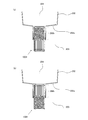
- FIG. 7 is a schematic cross-sectional view showing a state in which the water purification cartridge 1004 is arranged in the housing portion 202b of the pod type water purifier.
- FIG. 7A shows a state in which the first opening 102 is arranged toward the raw water storage unit
- FIG. 7B shows a state in which the second opening 103 is arranged toward the raw water storage unit.
- the water purifier accommodating portion 202b is formed to be inclined so that the horizontal cross-sectional area decreases from the top to the bottom. Moreover, it is preferable that any cross-sectional center in the horizontal direction of the accommodating part of a water purifier is located on the centerline along the up-down direction of a accommodating part.
- An O-ring 110 provided in the vicinity of the center of the water purification cartridge 1004 in the vertical direction is fitted in close contact with the side wall of the housing portion 202b. The water-purifying cartridge is pressed against the O-ring and the side wall of the housing portion by its own weight, and is liquid-tightly fitted.
- the opening surfaces of the first opening portion 102 and the second opening portion 103 are positioned below the height of the upper end of the housing portion even in a state of being arranged in the housing portion in an arbitrary direction.
- the water purification cartridge may have a configuration in which the side wall of the container is inclined so that the horizontal cross-sectional area decreases from the vicinity of the center in the vertical direction toward both ends. Moreover, it is preferable that any cross-sectional center in the horizontal direction of a container side wall part is located on the centerline in alignment with the up-down direction of a container. By setting it as such a container, it becomes easy to insert in an accommodating part from arbitrary directions. Examples of such a container shape include a substantially barrel shape.
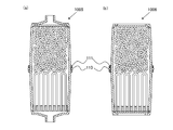
- FIG. 9 shows the external shape of the water purification cartridge shown in FIG.
- the water purification cartridge shown in FIG. 8 has a container whose side wall is inclined so that the cross-sectional area in the horizontal direction decreases from near the center toward both ends.
- An O-ring 110 is provided as a fitting portion near the center of the container.
- an approximately barrel-shaped container is used, and by providing the first opening and the second opening on the upper and lower surfaces of the container, the area of the opening is reduced. It is possible to provide a water purification cartridge that can be widely used, can effectively secure the volume of the filter medium and the hollow fiber membrane, and is excellent in raw water introduction efficiency and filtration efficiency.
- the opening surfaces of the first opening 102 and the second opening 103 are arranged at the upper end of the housing portion in a state of being arranged in the housing portion in an arbitrary direction. It is preferable to be located below the height.
- the fitting portion may be provided in the vicinity of both ends of the side surface of the container.
- the water purification cartridge can be arranged in the accommodating part in an arbitrary direction.
- a first O-ring 112a is fitted into a first groove constituting portion 113a provided in the vicinity of the upper end of the container side surface to constitute a first fitting portion.
- a second O-ring 112b is fitted into a second groove constituting portion 113b provided near the lower end of the container side surface to constitute a second fitting portion.
- FIG. 12 (a) is a schematic cross-sectional view for explaining an embodiment of a pressure filtration type according to this embodiment.
- FIG. 12B is a schematic cross-sectional view showing a state where the pressure filtration type water purification cartridge shown in FIG. 12A is connected to the raw water supply pipe 142 and the purified water delivery pipe 143.
- the raw water supply pipe 142 and the purified water delivery pipe 143 can be grasped as part of the configuration of the water purifier.
- 122 represents the first connecting portion
- 123 represents the second connecting portion.
- the first opening portion 102 is exposed at the first connecting portion 122
- the second opening portion 103 is exposed at the second connecting portion 123.
- the 1st connection part 122 is provided in the 1st cover part 101a
- the 2nd connection part 123 is provided in the 2nd cover part 101c.
- the first connecting portion 122 is connected to the raw water supply pipe 142 via the first connection member 132 in FIG. 12B, but can also be connected to the purified water delivery pipe 143 via the second connection member 133. It is configured. Moreover, although the 2nd connection part 123 is connected to the purified water delivery pipe 143 via the 2nd connection member 133 in FIG.12 (b), the raw
- the raw water flows into the first opening 102.
- the raw water flows from the first opening 102 to the filter medium 104 and is filtered through the filter medium 104 and the hollow fiber membrane 105.
- the obtained purified water is sent from the second opening 103 to the purified water delivery pipe 143.
- a faucet is provided at the end of the purified water delivery pipe 143.
- the second connecting portion 123 is connected to the raw water supply pipe 142 and the first connecting portion 122 is connected to the purified water delivery pipe 143
- the raw water flows into the second opening 103.
- the raw water then flows from the second opening 103 to the hollow fiber membrane 105 and is filtered through the hollow fiber membrane 105 and the filter medium 104.
- the obtained purified water is sent from the first opening 102 to the purified water delivery pipe 143.
- Such a connection state is effective when the heavy metal contained in the raw water is present in a particle state.
- the connecting portion and the connecting member are not particularly limited, and for example, a conventional method can be adopted. If each of the first connecting portion and the second connecting portion can be connected to each of the first connecting member and the second connecting member, it can be connected in any direction.
- the water purification cartridge according to the present embodiment can be installed in, for example, a sink, but is not limited to this.
- Example 1 In this example, a water purification cartridge having the structure shown in FIG. 1 was produced and evaluated.
- an H-type weak cation exchange resin (weakly acidic cation exchange resin, MR type, manufactured by Organo Corporation, trade name: Amberlite (registered trademark) IRC76) was used.
- an MF membrane membrane area: 0.16 m 2 , Mitsubishi Rayon Co., Ltd., trade name: EX270 was used.
- the prepared water purification cartridge was set in a water purifier housing having the structure shown in FIG. 2 and water was passed in accordance with NSF / ANSI 50 Lead (pH 8.5). The direction to arrange was evaluated about the case where the 1st opening was arranged towards the raw water storage part, and the case where the 2nd opening was arranged towards the raw water storage part, respectively.
- FIG. 13 shows the results of integrated flow rate and Pb concentration of filtered water.
- ⁇ is the result of evaluating the hollow fiber membrane side facing the raw water reservoir so that water flows in the order from the hollow fiber membrane to the filter medium.
- delta) is the result of having arrange
- the water purification cartridge according to the present invention can effectively remove heavy metals by selecting the direction of arrangement according to the water quality.
Landscapes
- Chemical & Material Sciences (AREA)
- Chemical Kinetics & Catalysis (AREA)
- Life Sciences & Earth Sciences (AREA)
- Hydrology & Water Resources (AREA)
- Engineering & Computer Science (AREA)
- Environmental & Geological Engineering (AREA)
- Water Supply & Treatment (AREA)
- Organic Chemistry (AREA)
- Water Treatment By Sorption (AREA)
- Separation Using Semi-Permeable Membranes (AREA)
- Treatment Of Water By Ion Exchange (AREA)
Abstract
本発明は、水質が異なる場合でも、原水に含まれる重金属を有効に除去することが可能な浄水カートリッジを提供することを目的とする。 本発明の一は、2つの開口部を有し、前記2つの開口部のうち任意の一方を原水導入口として利用することができ、他方を浄水排出口として利用することができる構造を持つ容器と、水のpHを変化させる吸着材を含む濾材と、中空糸膜と、を具備し、前記濾材および前記中空糸膜が前記2つの開口部の一方から他方に向かって順に前記容器内に配置されている浄水カートリッジである。
Description
本発明は浄水カートリッジに関する。また、本発明はその浄水カートリッジが装着された浄水器に関する。
浄水カートリッジが装着された浄水器として、例えばポット型の浄水器が知られている。このポット型の浄水器は、上側に位置する原水貯留部と、下側に位置する浄水貯留部との間に浄水カートリッジを介在させる構造になっている。原水貯留部に貯留される原水は自重により浄水カートリッジを通って浄水貯留部に流れ、浄水カートリッジ内にて浄化される。ポット型の浄水器に装着する浄水カートリッジとしては、例えば特許文献1に記載されるものが挙げられる。このような浄水カートリッジでは、濾材としてイオン交換樹脂が用いられる。
ここで、浄水カートリッジでは、水道水中に含まれる鉛等の重金属を除去するため、キレート樹脂やイオン交換樹脂等の吸着材が用いられている。また、吸着材に加えて、中空糸膜も用いられており、中空糸膜は一般的に吸着材の下流側に配置されている。
しかし、水道水中に含まれる重金属の状態は国や地域で異なっており、従来のイオン交換樹脂等の水のpHを変化させる吸着材を用いた浄水カートリッジでは、重金属を十分に除去することができない場合があった。より具体的に説明すると、例えば、水道水のpHが8付近の場合、水道水中に含まれる鉛はイオン状態よりも粒子状態で多く存在する。このような場合、原水導入口から容器内に入り込んだ粒子状の鉛は吸着材で吸着され難いため、吸着層の下流側に流れる。また、吸着層の下流側ではイオン交換樹脂等によって水のpHが変化し、酸性に傾く。水のpHが酸性に傾くと鉛は粒子状体よりもイオン状態で多く存在する。そのため、吸着層の下流側で鉛がイオン状態となり、中空糸膜を通過して出てきてしまう場合がある。
そこで、本発明は、水質が異なる場合でも、原水に含まれる重金属を有効に除去することが可能な浄水カートリッジを提供することを目的とする。
そこで、本発明は、第一の開口部と第二の開口部を有し、前記第一の開口部及び前記第二の開口部のうち任意の一方を原水導入口として利用することができ、他方を浄水排出口として利用することができる構造を有する容器と、重金属を吸着できる吸着材を含む濾材と、中空糸膜と、を具備し、前記濾材および前記中空糸膜が前記第一の開口部及び前記第二の開口部の一方から他方に向かって順に前記容器内に配置されている浄水カートリッジである。
本発明に係る浄水カートリッジは、水質の状況に応じて水源に取り付ける方向を選択することができるため、国や地域における水質の違いを問わずに原水に含まれる重金属を効率よく除去することができる。
本発明の浄水カートリッジは、第一の開口部と第二の開口部を有し、前記第一の開口部及び前記第二の開口部のうち任意の一方を原水導入口として利用することができ、他方を浄水排出口として利用することができる構造を有する容器を備える。また、本発明の浄水カートリッジは、重金属を吸着できる吸着材を含む濾材と、中空糸膜と、を、前記容器内に具備する。前記濾材および前記中空糸膜が前記第一の開口部及び前記第二の開口部の一方から他方に向かって順に前記容器内に配置されている。
本発明の構成とすることにより、水質の状況に応じて水源に取り付ける方向を選択することができるため、国や地域における水質の違いを問わずに原水に含まれる重金属を効率よく除去することができる。
以下、本発明の浄水カートリッジの実施形態について、図を参照にして詳細に説明する。なお、本発明は以下の実施形態に限定されるものではない。
(実施形態1)
図1は、本発明の実施形態に係る自重濾過型の浄水カートリッジの構造例を説明するための概略断面図である。
図1は、本発明の実施形態に係る自重濾過型の浄水カートリッジの構造例を説明するための概略断面図である。
図1において、浄水カートリッジ1001は、濾材104と中空糸膜105を内部に収容する容器101を備える。濾材104は、重金属を吸着できる吸着材を含む。容器101は、濾材104及び中空糸膜105を収容する筒状のケース体101bと、ケース101bの片端に配置される第一の蓋部101aと、ケース体101bのもう一方の端に配置される第二の蓋部101cと、から主に構成されている。第一の蓋部101aの中央には第一の開口部102が設けられており、第二の蓋部101cの中央にも第二の開口部103が設けられている。濾材104及び中空糸膜105は第一の開口部102から第二の開口部に向かって順に容器101内に配置されている。
中空糸膜105は、ケース体102bの第二の蓋部103側の端にポッティング樹脂106を用いて容器内に固定されている。中空糸膜105の端部はポッティング樹脂106の中空糸膜が配置される側の面と反対の面側に開口している。この中空糸膜の開口から水が出入りすることができる。濾材104は通水可能な隔壁107により容器内に収納されている。
第一の蓋部101aとケース体101b、第二の蓋部101cとケース体101bとの連結には、例えば接着や溶着を用いることができる。
第一の開口部102及び第二の開口部103の任意の一方は、原水を容器内に取り入れる原水導入口及び浄水を容器外に送水する浄水排出口のいずれとしても機能することができる。第一の開口部102が原水導入口として機能する場合、第二の開口部103は浄水排出口として機能し、第二の開口部103が原水導入口として機能する場合、第一の開口部102は浄水排出口として機能する。
図2に、図1に示した浄水カートリッジ1001を備える浄水器の構成例を示す。図2では、第一の開口部102を上向きにして浄水カートリッジ1001を収容部202bに配置している。本明細書における浄水カートリッジの上下方向は、図2のように収容部に配置した状態における方向を表す。
図2に示す浄水器200はいわゆるポット型浄水器である。浄水器200は、水道水等の原水を供給して貯留させておく原水貯留部204と、原水貯留部204の底部に装着される浄水カートリッジ1001と、原水貯留部204及び浄水カートリッジ1001の下方に位置する浄水貯留部203とで主体を成す。原水貯留部204内に貯留されていた原水は自重により浄水カートリッジ1001を通過する際に浄化され、浄水貯留部203にまで流下する。
浄水器200は、上端が開口した有底筒型の外容器201と、外容器201の上端開口から挿入されて外容器201内に配置される上端が開口した有底筒型の内容器202とを具備している。内容器202は、外容器201の半分程度又はそれ以下の深さで配置されており、外容器201の上半部に対して所定の隙間205を除く部分で隙間なく嵌合することで、内容器202内に上記の原水貯留部204を形成している。また、内容器202の底壁202aと外容器201の底壁201aとの間に浄水貯留部203が設けられている。隙間205は浄水貯留部203から上方に延設されるように形成され、浄水を注ぐ際の注ぎ路として機能する。
内容器202の上端開口には、上蓋部206が嵌め込まれている。上蓋部206には、例えば、中央には給水口を開口させ、該給水口をその上方から塞ぐ開閉自在のフラップを設けることができる。また、隙間205の上端に形成される開口は注ぎ口として機能し、該注ぎ口には注ぎ蓋207が設けられている。
内容器の底壁202aには浄水カートリッジを収容する収容部202bが設けられており、内容器の底壁202aはその収容部202bに向かって緩やかな下り傾斜に形成されている。浄水カートリッジの収容部202bは、内容器の底壁202aに浄水貯留部に向かって凹設されている。浄水カートリッジ1001は、収容部202bに上方から嵌め込んで装着される。収容部202bの底部中央は開口させており、収容部202b及びこの底部の開口を介して、つまり収容部202bに装着される浄水カートリッジ1001を介して、原水貯留部204とこの下方に位置する浄水貯留部203とが連通する構造となっている。
浄水カートリッジ1001の収納部202bへの装着は、ゴムパッキンを用いた差込式の他に、ねじ込み式やラチェット方式等を用いることができ、特に制限されるものではない。
図2では、第一の開口部102を上向きにして浄水カートリッジ1001を収容部202bに配置している。図2の状態において、第一の開口部102が原水導入口として機能し、第二の開口部103が浄水排出口として機能する。原水貯留部204にある原水は、自重によって第一の開口部102から容器内に入る。そして、濾材104により濾過された水は、中空糸膜105によりさらに濾過され、中空糸膜の端部開口から流れ出る。そして、得られた浄水は浄水排出口として機能する第二の開口部103から浄水貯留部203に排出される。
ここで、水道水のpHが8より小さい場合、水道水中に含まれる鉛は粒子状態よりもイオン状態で多く存在する傾向がある。イオン状態の鉛は濾材で吸着しやすいため、図2に示すように、第一の開口部102を上向きに配置して、中空糸膜よりも先に濾材に原水が流れるように配置した方が鉛を効率よく除去することができる。一方、水道水のPHが8より大きい場合、水道水中に含まれる鉛は粒子状態で多く存在する傾向がある。この場合、図3に示すように、第二の開口部103を上向きに配置して、濾材の前に中空糸膜で鉛を除去することにより、より効率的に鉛を除去することができる。図3の状態において、第二の開口部103が原水導入口として機能し、第一の開口部102が浄水排出口として機能する。
したがって、本発明に係る浄水カートリッジは、原水の状態に応じて配置向きを選択することにより、原水中に含まれる重金属を効率的に除去することができる。
本発明における濾材は、重金属を吸着できる吸着材(以下、重金属吸着材と略す)を含む。
重金属吸着材としては、重金属を吸着可能であれば特に制限されるものではないが、例えば、イオン交換樹脂やキレート樹脂を用いることができる。
イオン交換樹脂は、合成樹脂の一種で分子構造の一部にイオン交換基として電離する構造を持っている。イオン交換樹脂は、そのイオン交換基の性質により陽イオン交換樹脂と陰イオン交換樹脂に分けられ、さらに、陽イオン交換樹脂は、イオン交換基の種類によりH型、Na型、K型などに分けられる。本発明においては、重金属の吸着性能の観点から、イオン交換樹脂のなかでもH型陽イオン交換樹脂を用いることが好ましい。H型陽イオン交換樹脂が有するイオン交換基としては、例えば、スルホン酸基、(メタ)アクリル酸基が挙げられる。(メタ)アクリル酸基を有する陽イオン交換樹脂は、一般に弱酸性陽イオン交換樹脂と呼ぶ。また、イオン交換樹脂は、樹脂母体にイオン交換を行なう官能基(交換基)をもつ合成樹脂であり、その樹脂が保持しているイオンと溶液中のイオンを交換することが出来る。イオン交換樹脂は官能基の種類から強酸性陽イオン交換樹脂、弱酸性陽イオン交換樹脂、強塩基性陰イオン交換樹脂、弱塩基性陰イオン交換樹脂の4種類に大別される。
キレート樹脂は、主に金属イオンとキレート(錯体)を作る官能基を導入した樹脂であり、キレートを形成することによって特定の金属イオンを捕捉することができる。キレート樹脂は、一般に、N、S、O、P等の電子供与元素を2個以上含んだキレート形成基を有しており、その組み合わせ構造によりイミノジ酢酸型、ポリアミン型、グルカミン型などに分けられる。本発明では、重金属を効率よく除去する観点から、イミノジ酢酸型のキレート樹脂が好ましい。
イオン交換樹脂やキレート樹脂は、その性状から、ゲル型、ポーラス型、ハイポーラス型、MR(macro-reticular)型などに分類される。ゲル型樹脂は、スチレンとジビニルベンゼン(DVB)の三次元構造により形成されるミクロポアのみを有する。ハイポーラス型樹脂およびMR型樹脂は、ミクロポアのほかにマクロポアを有する。ハイポーラス型樹脂およびMR型樹脂は、一般的に高架橋度のものが多い。ポーラス型は、ゲル型とハイポーラス型の中間に位置するものである。本発明で用いるH型陽イオン交換樹脂およびキレート樹脂は、ハイポーラス型またはMR型が好ましく、MR型がより好ましい。
また、濾材は、重金属吸着材以外の他の吸着材も含んでもよい。このような吸着材としては、例えば、天然物系吸着材(天然ゼオライト、銀ゼオライト、酸性白土等)、又は合成物系吸着材(合成ゼオライト、細菌吸着ポリマー、リン鉱石、モレキュラーシーブ、シリカゲル、シリカアルミナゲル、多孔質ガラス等)等の無機系吸着材が挙げられる。このような吸着材としては、例えば、粉末状吸着材若しくは該粉末状吸着材を造粒した粒状吸着材、又は繊維状吸着材等が挙げられる。また、吸着材として、活性炭を用いることが好ましく、活性炭としては、例えば、粉末状活性炭、粒状活性炭、繊維状活性炭、ブロック状活性炭、押出成形活性炭、成形活性炭、合成物系粒状活性炭、合成物系繊維状活性炭等が挙げられる。これらの中でも、原水中の残留塩素やカビ臭、トリハロメタンなどの有機化合物の吸着力に優れた活性炭が好適に用いられる。
さらに、他の吸着材として、残留塩素の除去に優れた脱塩素剤も好ましく用いることができる。脱塩素剤としては、塩素除去の効果を長く維持することができる亜硫酸カルシウムやアスコルビン酸ナトリウムなどが好ましい。
濾材は、濾材全体に対して重金属吸着材を、例えば10体積%以上含むことができ、20体積%以上含むことが好ましく、30体積%以上含むことがより好ましく、40体積%以上含むことがさらに好ましい。
なお、吸着材は1種で又は2種以上を組み合わせて用いることができる。
本発明における中空糸膜としては、特に限定されるものではないが、例えば、セルロース系、ポリオレフィン(ポリエチレン、ポリプロピレン)系、ポリビニルアルコール系、エチレン・ビニルアルコール共重合体、ポリエーテル系、ポリメタクリル酸メチル(PMMA)系、ポリスルフォン系、ポリアクリロニトリル系、ポリ四弗化エチレン(テフロン(登録商標))系、ポリカーボネイト系、ポリエステル系、ポリアミド系、芳香族ポリアミド系などの各種材料からなるものが挙げられる。これらの中でも、中空糸膜の取扱い性や加工特性等、更には廃棄時に焼却可能であることなどを考慮すると、ポリエチレンやポリプロピレン等のポリオレフィン系の中空糸膜が好ましい。
また、特に限定されるものではないが、中空糸膜について、外径は20~2000μm、孔径は0.01~1μm、空孔率は20~90%、膜厚は5~300μmのものが好ましい。また、中空糸膜は表面に親水基を有する、いわゆる親水化中空糸膜であることが望ましい。
容器側面の形状としては、特に制限されるものではないが、例えば略円筒状とすることができる。
第一の開口部及び第二の開口部の開口面の形状は、特に制限されるものではないが、例えば、円形状、楕円形状、多角形状とすることができ、不定形状であってもよい。また、第一の開口部及び第二の開口部は、特に制限されるものではないが、同じ形状であることが好ましい。特に第一の開口部及び第二の開口部を構成するそれぞれの部材が同じ形状であれば任意の向きで収容部に配置しやすくなる。
(実施形態2)
図4は、本実施形態の好ましい構成例を示す模式的断面図である。
図4は、本実施形態の好ましい構成例を示す模式的断面図である。
図4において、容器の形状は、第一の蓋部101a及び第二の蓋部101cも含めて略円柱状である。略円柱状の容器上面には第一の開口部102が設けられており、第一の開口部102の直下には濾材104を容器内に収納するための通水性を有する隔壁107が設けられている。中空糸膜105はポッティング樹脂106により容器内に収納されている。略円柱状の容器下面には第二の開口部102が設けられている。第二の開口部102とポッティング樹脂106の間にはフィルター108が設けられている。フィルター108を設けることにより、中空糸膜側を上向きにして使用する際に、比較的大きな不純物を補足することができる。
図5は、図4に示す浄水カートリッジ1002を収容部202bに配置した状態を示す模式的断面図である。
図5において、浄水カートリッジ1002を収容部202bに配置した際に、第一の開口部102の開口面が収容部の上端に比べて同じ高さ又はそれよりも下側に位置している。つまり、第一の開口部102の開口面が収容部の上端の高さ以下となっている。
本発明に係る浄水カートリッジは、浄水器の収容部に任意の向きで配置した際、第一の開口部102及び第二の開口部103の開口面が収容部の上端の高さ以下に位置する構成とすることが好ましい。このような構成とすることにより、どちらの向きで浄水カートリッジを収容部に配置しても原水をより効率的に容器内に導入することができる。浄水カートリッジの容器形状を略円柱状とすることにより、第一の開口部の面積及び第二の開口部の面積を広くとれ、濾材や中空糸膜の体積を有効に確保でき、原水導入効率及び濾過効率に優れる浄水カートリッジを提供することができる。
(実施形態3)
本実施形態の浄水カートリッジは、容器の上下方向の中央付近に収容部との嵌合部が設けられている構成を有する。該嵌合部と収容部の一部が嵌まることにより、浄水カートリッジが液密に収容される。容器の中央付近に収容部との嵌合部が設けられていることにより、任意の向きで収容部に挿入しても原水を容器内に導入する開口の位置を一定にすることができる。
本実施形態の浄水カートリッジは、容器の上下方向の中央付近に収容部との嵌合部が設けられている構成を有する。該嵌合部と収容部の一部が嵌まることにより、浄水カートリッジが液密に収容される。容器の中央付近に収容部との嵌合部が設けられていることにより、任意の向きで収容部に挿入しても原水を容器内に導入する開口の位置を一定にすることができる。
また、嵌合部は容器の中央付近に周方向に設けられていることが好ましい。また、嵌合部は容器側面の中央付近に周方向に設けられていることがより好ましい。
嵌合方式は、弾性体を用いた差込式、ねじ込み式やラチェット方式等を用いることができ、特に制限されるものではない。脱着の容易性の観点から、弾性体を用いた差込式が好ましい。
なお、浄水カートリッジの浄水器内への配置は、収容部の上側から挿入する場合に限られるものではなく、下側から挿入して脱着する構成とすることも可能である。
図6は、本実施形態の好ましい構成例を示す模式的断面図である。
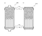
図6に示す浄水カートリッジ1003は、図1に示す浄水カートリッジ1001の容器の上下方向の中央部に弾性体からなるOリング110を設けた構成である(図6(a))。Oリング110は溝構成部111にはめ込まれている。同様に、浄水カートリッジ1004は、図4に示す浄水カートリッジ1002の容器の上下方向の中央部に弾性体からなるOリング110を設けた構成である(図6(b))。
図7は、浄水カートリッジ1004をポッド型浄水器の収容部202bに配置した状態を示す模式的断面図である。図7(a)は第一の開口部102を原水貯留部に向けて配置した状態を示し、図7(b)は第二の開口部103を原水貯留部に向けて配置した状態を示す。
浄水器の収容部202bは、上から下に向かって水平方向の断面積が小さくなるように傾斜をつけられて形成されている。また、浄水器の収容部の水平方向におけるいずれの断面中心が、収容部の上下方向に沿う中心線上に位置することが好ましい。浄水カートリッジ1004の上下方向の中央付近に設けられたOリング110が収容部202bの側壁と液密に接して嵌合している。浄水カートリッジの自重によりOリングと収容部側壁に押しつけられ、液密に嵌合される。
図7においては、任意の向きで収容部内に配置させた状態でも、第一の開口部102及び第二の開口部103の開口面が収容部の上端の高さ以下に位置している。
(実施形態4)
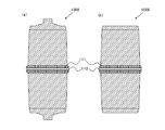
浄水カートリッジは、図8に示すように、容器の側壁が上下方向の中央付近から両端側に向かって水平方向の断面積が小さくなるように傾斜している構成とすることもできる。また、容器側壁部分の水平方向におけるいずれの断面中心が、容器の上下方向に沿う中心線上に位置することが好ましい。このような容器とすることにより、収容部内に任意の方向から挿入し易くなる。このような容器形状としては、例えば略樽形状が挙げられる。図9に、図8に示す浄水カートリッジの外観形状を示す。
浄水カートリッジは、図8に示すように、容器の側壁が上下方向の中央付近から両端側に向かって水平方向の断面積が小さくなるように傾斜している構成とすることもできる。また、容器側壁部分の水平方向におけるいずれの断面中心が、容器の上下方向に沿う中心線上に位置することが好ましい。このような容器とすることにより、収容部内に任意の方向から挿入し易くなる。このような容器形状としては、例えば略樽形状が挙げられる。図9に、図8に示す浄水カートリッジの外観形状を示す。
図8に示す浄水カートリッジは、側壁が中央付近から両端側に向かって水平方向の断面積が小さくなるように傾斜している容器を有する。また、該容器の中央付近に嵌合部としてOリング110が設けられている。図8(b)に示す浄水カートリッジ1006のように、略樽形状の容器を用い、該容器の上面及び下面に第一の開口部及び第二の開口部を設けることにより、開口部の面積を広くとれ、濾材や中空糸膜の体積を有効に確保でき、原水導入効率及び濾過効率に優れる浄水カートリッジを提供することができる。
また、本実施形態においても、図10に示すように、任意の向きで収容部内に配置させた状態で、第一の開口部102及び第二の開口部103の開口面が収容部の上端の高さ以下に位置することが好ましい。
(実施形態5)
上述の実施形態では、中央付近に嵌合部を設ける構成を示したが、図11に示すように、容器側面の両端付近に嵌合部をそれぞれ設ける構成とすることもできる。容器側面の上端及び下端付近にそれぞれ収容部との嵌合部を設けることにより、任意の向きで浄水カートリッジを収容部に配置することができる。図11では、容器側面の上端付近に設けられた第一の溝構成部113aに第一のOリング112aが嵌められ、第一の嵌合部を構成している。また、容器側面の下端付近に設けられた第二の溝構成部113bに第二のOリング112bが嵌められ、第二の嵌合部を構成している。
上述の実施形態では、中央付近に嵌合部を設ける構成を示したが、図11に示すように、容器側面の両端付近に嵌合部をそれぞれ設ける構成とすることもできる。容器側面の上端及び下端付近にそれぞれ収容部との嵌合部を設けることにより、任意の向きで浄水カートリッジを収容部に配置することができる。図11では、容器側面の上端付近に設けられた第一の溝構成部113aに第一のOリング112aが嵌められ、第一の嵌合部を構成している。また、容器側面の下端付近に設けられた第二の溝構成部113bに第二のOリング112bが嵌められ、第二の嵌合部を構成している。
(実施形態6)
上述の実施形態では、主に自重濾過型の場合について説明したが、本実施形態では加圧濾過型の場合について説明する。
上述の実施形態では、主に自重濾過型の場合について説明したが、本実施形態では加圧濾過型の場合について説明する。
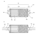
図12(a)は本実施形態に係る加圧濾過型の実施形態について説明するための模式的断面図である。図12(b)は図12(a)に示す加圧濾過型の浄水カートリッジを原水供給管142及び浄水送出管143に接続した状態を示す模式的断面図である。原水供給管142と浄水送出管143は浄水器の構成の一部として把握できる。
図12(a)において、122は第一の連結部を表し、123は第二の連結部を表す。第一の連結部122に第一の開口部102が露出し、第二の連結部123に第二の開口部103が露出している。第一の連結部122は第一の蓋部101aに設けられ、第二の連結部123は第二の蓋部101cに設けられている。
第一の連結部122は、図12(b)では第一の接続部材132を介して原水供給管142に接続されているが、浄水送出管143とも第二の接続部材133を介して接続可能に構成されている。また、第二の連結部123は、図12(b)では第二の接続部材133を介して浄水送出管143に接続されているが、原水供給管142とも第一の接続部材132を介して接続可能に構成されている。つまり、本実施形態は任意の向きで原水供給管及び浄水送出管に接続可能である。
第一の連結部122が原水供給管142と接続し、第二の連結部123が浄水送出管143と接続することにより、第一の開口部102に原水が流れ込む。そして、原水は第一の開口部102から濾材104へ流れ、濾材104及び中空糸膜105を通って濾過される。得られた浄水は第二の開口部103から浄水送出管143へと送られる。浄水送出管143の先には蛇口が設けられる。このような接続状態は、原水に含まれる重金属がイオン状態で多く存在する場合に有効である。
一方、第二の連結部123が原水供給管142と接続し、第一の連結部122が浄水送出管143と接続することにより、第二の開口部103に原水が流れ込む。そして、原水は第二の開口部103から中空糸膜105へ流れ、中空糸膜105及び濾材104を通って濾過される。得られた浄水は第一の開口部102から浄水送出管143へと送られる。このような接続状態は、原水に含まれる重金属が粒子状態で多く存在する場合に有効である。
連結部や接続部材としては、特に制限されるものではなく、例えば従来の方式を採用可能である。第一の連結部と第二の連結部のそれぞれが第一の接続部材と第二の接続部材のそれぞれに接続可能な構成とすれば、任意の向きで接続可能とすることができる。
本実施系の浄水カートリッジは例えばシンク内等に設置することができるが特にこれに限定されるものではない。
以下、本発明を実施例により具体的に説明する。
〔実施例1〕
本実施例では、図1に示す構造を有する浄水カートリッジを作製し、評価した。
本実施例では、図1に示す構造を有する浄水カートリッジを作製し、評価した。
重金属吸着材としては、H型弱陽イオン交換樹脂(弱酸性陽イオン交換樹脂、MR型、オルガノ社製、商品名:アンバーライト(登録商標)IRC76)を用いた。該重金属吸着材と、活性炭(20/42メッシュ、クラレケミカル株式会製、商品名:GW20/42)とを50/50(体積比)で混合した濾材を用いた。
中空糸膜としては、MF膜(膜面積:0.16m2、三菱レイヨン株式会社製、商品名:EX270)を用いた。
作製した浄水カートリッジを、図2に示す構造を有する浄水器の収容部にセットし、NSF/ANSI 50 Lead(pH8.5)に従って通水した。配置する向きは、第一の開口部を原水貯留部に向けて配置した場合と第二の開口部を原水貯留部に向けて配置した場合についてそれぞれ評価した。
Pbは、原子吸光により測定した。
図13に、積算流量と濾過水のPb濃度の結果を示す。図13において、○は中空糸膜から濾過材の順に水が流れるように中空糸膜側を原水貯留部に向けて配置し、評価した結果である。△は濾過材から中空糸膜の順に水が流れるように濾過材側を原水貯留部に向けて配置し、評価した結果である。
図13に示されるように、pH8.5の場合は、原水を先に中空糸膜に通らせてから濾材に誘導させることにより、重金属をより効率よく除去できることがわかる。したがって、本発明に係る浄水カートリッジは水質に応じて配置する向きを選択することにより重金属を有効に除去することができることが確認された。
101 容器
101a 第一の蓋部
101b ケース体
101c 第二の蓋部
102 第一の開口部
103 第二の開口部
104 濾材
105 中空糸膜
106 ポッティング樹脂
107 通水性を有する隔壁
108 フィルター
110 Oリング
111 溝構成部
112 Oリング
113 溝構成部
122 第一の連結部
123 第二の連結部
132 第一の接続部材
133 第二の接続部材
142 原水供給管
143 浄水送出管
200 浄水器
201 外容器
202 内容器
202b カートリッジ収容部
203 浄水貯留部
204 原水貯留部
205 隙間
206 上蓋部
207 注ぎ蓋
101a 第一の蓋部
101b ケース体
101c 第二の蓋部
102 第一の開口部
103 第二の開口部
104 濾材
105 中空糸膜
106 ポッティング樹脂
107 通水性を有する隔壁
108 フィルター
110 Oリング
111 溝構成部
112 Oリング
113 溝構成部
122 第一の連結部
123 第二の連結部
132 第一の接続部材
133 第二の接続部材
142 原水供給管
143 浄水送出管
200 浄水器
201 外容器
202 内容器
202b カートリッジ収容部
203 浄水貯留部
204 原水貯留部
205 隙間
206 上蓋部
207 注ぎ蓋
Claims (15)
- 第一の開口部と第二の開口部を有し、前記第一の開口部及び前記第二の開口部のうち任意の一方を原水導入口として利用することができ、他方を浄水排出口として利用することができる構造を有する容器と、
重金属を吸着できる吸着材を含む濾材と、
中空糸膜と、
を具備し、
前記濾材および前記中空糸膜が前記第一の開口部及び前記第二の開口部の一方から他方に向かって順に前記容器内に配置されている浄水カートリッジ。 - 前記吸着材が、H型陽イオン交換樹脂又はキレート樹脂である請求項1に記載の浄水カートリッジ。
- 前記容器は、前記濾材と前記中空糸膜を内部に収納するケース体と、前記ケース体の任意の一方の端部に前記第一の開口部を有する第一の蓋部と、前記ケース体の他方の端部に前記第二の開口部を有する第二の蓋部と、を有する請求項1又は2に記載の浄水カートリッジ。
- 自重濾過型であって、
浄水器の原水貯留部と浄水貯留部との間に設けられたカートリッジ収容部に、前記第一の開口部及び前記第二の開口部のうち任意の一方を前記原水貯留部に、他方を前記浄水貯留部に連通させて配置することができる請求項1乃至3のいずれかに記載の浄水カートリッジ。 - 前記容器の上下方向の中央付近に前記カートリッジ収容部との嵌合部が設けられている請求項4に記載の浄水カートリッジ。
- 前記容器の形状が略円柱状である請求項5に記載の浄水カートリッジ。
- 前記容器の側壁が上下方向の中央付近から両端側に向かって水平方向の断面積が小さくなるように傾斜している請求項5に記載の浄水カートリッジ。
- 前記容器の形状が略樽形状である請求項7に記載の浄水カートリッジ。
- 加圧濾過型であって、
前記第一の開口部及び前記第二の開口部の任意の一方を原水を供給するための原水供給管に接続でき、他方を浄水を送水するための浄水送出管に接続できる請求項1乃至3のいずれかに記載の浄水カートリッジ。 - 前記第一の開口部を露出する第一の連結部と、前記第二の開口部を露出する第二の連結部とを有し、
前記第一の連結部及び第二の連結部のそれぞれは、前記原水供給管及び前記浄水送出管のどちらにも接続可能な構成を有する請求項9に記載の浄水カートリッジ。 - 請求項4乃至8のいずれかに記載の浄水カートリッジを備え、原水貯留部と浄水貯留部との間に設けられたカートリッジ収容部を有する自重濾過型の浄水器。
- 前記浄水カートリッジは、弾性体からなるOリングよりなる嵌合部を有し、前記Oリングが前記カートリッジ収容部の側壁と接することにより液密に収容される請求項11に記載の自重濾過型の浄水器。
- 前記カートリッジ収容部に前記第一の開口部を前記原水貯留部に向けて配置した際、前記第一の開口部の開口面が前記カートリッジ収容部の上端の高さ以下となり、
前記カートリッジ収容部に前記第二の開口部を前記原水貯留部に向けて配置した際、前記第二の開口部の開口面が前記カートリッジ収容部の上端の高さ以下となる請求項11又は12に記載の自重濾過型の浄水器。 - 前記カートリッジ収容部の側壁は、該カートリッジ収容部の水平方向の断面積が下側から上側に向かって大きくなるように傾斜している請求項13に記載の自重濾過型の浄水器。
- 請求項9又は10に記載の浄水カートリッジを備え、原水供給管と浄水送出管を有する加圧濾過型の浄水器。
Priority Applications (3)
| Application Number | Priority Date | Filing Date | Title |
|---|---|---|---|
| CN201280028553.7A CN103702943A (zh) | 2011-06-10 | 2012-06-07 | 净水滤筒以及净水器 |
| JP2012528578A JP5609978B2 (ja) | 2011-06-10 | 2012-06-07 | 浄水カートリッジおよび浄水器 |
| EP12796824.6A EP2733120A4 (en) | 2011-06-10 | 2012-06-07 | WATER CLEANING CARTRIDGE AND WATER CLEANER |
Applications Claiming Priority (2)
| Application Number | Priority Date | Filing Date | Title |
|---|---|---|---|
| JP2011-130418 | 2011-06-10 | ||
| JP2011130418 | 2011-06-10 |
Publications (1)
| Publication Number | Publication Date |
|---|---|
| WO2012169577A1 true WO2012169577A1 (ja) | 2012-12-13 |
Family
ID=47296134
Family Applications (1)
| Application Number | Title | Priority Date | Filing Date |
|---|---|---|---|
| PCT/JP2012/064657 Ceased WO2012169577A1 (ja) | 2011-06-10 | 2012-06-07 | 浄水カートリッジおよび浄水器 |
Country Status (4)
| Country | Link |
|---|---|
| EP (1) | EP2733120A4 (ja) |
| JP (1) | JP5609978B2 (ja) |
| CN (1) | CN103702943A (ja) |
| WO (1) | WO2012169577A1 (ja) |
Cited By (3)
| Publication number | Priority date | Publication date | Assignee | Title |
|---|---|---|---|---|
| KR20180132718A (ko) * | 2016-04-22 | 2018-12-12 | 폴 코포레이션 | 수처리 장치 |
| JP2019514668A (ja) * | 2016-04-22 | 2019-06-06 | ポール・コーポレーションPall Corporation | 水処理装置 |
| CN117023742A (zh) * | 2023-08-16 | 2023-11-10 | 江苏久智环境科技服务有限公司 | 一种蓄水水储罐净水装置 |
Families Citing this family (4)
| Publication number | Priority date | Publication date | Assignee | Title |
|---|---|---|---|---|
| WO2017204743A1 (en) * | 2016-05-23 | 2017-11-30 | Asxban Technologies Pte Ltd | An apparatus for treating fluid having contaminants |
| CN105948284A (zh) * | 2016-07-17 | 2016-09-21 | 珠海大卫卫浴科技有限公司 | 一种外置式净化水与反渗透过滤水龙头 |
| DE102020129849B4 (de) * | 2020-11-12 | 2026-01-15 | Bwt Holding Gmbh | Wasserfilter, dessen Verwendung und Verfahren zur Aufbereitung von Trinkwasser |
| KR20240100119A (ko) * | 2022-12-22 | 2024-07-01 | 엘지전자 주식회사 | 물 여과 장치 |
Citations (6)
| Publication number | Priority date | Publication date | Assignee | Title |
|---|---|---|---|---|
| JPH0183487U (ja) * | 1987-11-16 | 1989-06-02 | ||
| JP2001252654A (ja) * | 2000-03-13 | 2001-09-18 | Yoshikazu Kumihigashi | 燃焼廃ガスまたは産業廃液の浄化方法および環境汚染物質の浄化装置 |
| JP2003514647A (ja) | 1999-11-02 | 2003-04-22 | ブリタ ゲーエムベーハー | 液体用濾過装置 |
| JP2004230335A (ja) * | 2003-01-31 | 2004-08-19 | Mitsubishi Rayon Co Ltd | 浄水カートリッジ及び浄水器 |
| WO2005110926A1 (ja) * | 2004-05-18 | 2005-11-24 | Mitsubishi Rayon Co., Ltd. | 浄水器 |
| JP2008214895A (ja) * | 2007-03-01 | 2008-09-18 | Kajima Corp | 地下水調査方法 |
Family Cites Families (6)
| Publication number | Priority date | Publication date | Assignee | Title |
|---|---|---|---|---|
| JPH07136649A (ja) * | 1993-11-17 | 1995-05-30 | Sanyo Electric Co Ltd | 浄水器 |
| JP3467606B2 (ja) * | 1994-06-21 | 2003-11-17 | 松下電器産業株式会社 | 浄水機能付冷水生成器 |
| JP3635934B2 (ja) * | 1998-08-17 | 2005-04-06 | 松下電工株式会社 | 浄水装置の洗浄方法 |
| EP1354857B1 (en) * | 2000-12-25 | 2008-02-20 | Mitsubishi Rayon Co., Ltd. | Pitcher type water purifier and purification cartridge for the water purifier |
| US20080105618A1 (en) * | 2006-10-27 | 2008-05-08 | Mesosystems Technology, Inc. | Method and apparatus for the removal of harmful contaminants from portable drinking water devices |
| CN201485338U (zh) * | 2009-07-21 | 2010-05-26 | 展银(香港)有限公司 | 可以分体组合和多级组合的自来水净化装置 |
-
2012
- 2012-06-07 CN CN201280028553.7A patent/CN103702943A/zh active Pending
- 2012-06-07 WO PCT/JP2012/064657 patent/WO2012169577A1/ja not_active Ceased
- 2012-06-07 EP EP12796824.6A patent/EP2733120A4/en not_active Withdrawn
- 2012-06-07 JP JP2012528578A patent/JP5609978B2/ja not_active Expired - Fee Related
Patent Citations (6)
| Publication number | Priority date | Publication date | Assignee | Title |
|---|---|---|---|---|
| JPH0183487U (ja) * | 1987-11-16 | 1989-06-02 | ||
| JP2003514647A (ja) | 1999-11-02 | 2003-04-22 | ブリタ ゲーエムベーハー | 液体用濾過装置 |
| JP2001252654A (ja) * | 2000-03-13 | 2001-09-18 | Yoshikazu Kumihigashi | 燃焼廃ガスまたは産業廃液の浄化方法および環境汚染物質の浄化装置 |
| JP2004230335A (ja) * | 2003-01-31 | 2004-08-19 | Mitsubishi Rayon Co Ltd | 浄水カートリッジ及び浄水器 |
| WO2005110926A1 (ja) * | 2004-05-18 | 2005-11-24 | Mitsubishi Rayon Co., Ltd. | 浄水器 |
| JP2008214895A (ja) * | 2007-03-01 | 2008-09-18 | Kajima Corp | 地下水調査方法 |
Non-Patent Citations (1)
| Title |
|---|
| See also references of EP2733120A4 |
Cited By (7)
| Publication number | Priority date | Publication date | Assignee | Title |
|---|---|---|---|---|
| KR20180132718A (ko) * | 2016-04-22 | 2018-12-12 | 폴 코포레이션 | 수처리 장치 |
| JP2019514668A (ja) * | 2016-04-22 | 2019-06-06 | ポール・コーポレーションPall Corporation | 水処理装置 |
| JP2019515785A (ja) * | 2016-04-22 | 2019-06-13 | ポール・コーポレーションPall Corporation | 水処理装置 |
| KR102376415B1 (ko) | 2016-04-22 | 2022-03-21 | 폴 코포레이션 | 수처리 장치 |
| JP7052178B2 (ja) | 2016-04-22 | 2022-04-12 | ポール・コーポレーション | 水処理装置 |
| CN117023742A (zh) * | 2023-08-16 | 2023-11-10 | 江苏久智环境科技服务有限公司 | 一种蓄水水储罐净水装置 |
| CN117023742B (zh) * | 2023-08-16 | 2024-04-09 | 江苏久智环境科技服务有限公司 | 一种蓄水水储罐净水装置 |
Also Published As
| Publication number | Publication date |
|---|---|
| JP5609978B2 (ja) | 2014-10-22 |
| EP2733120A4 (en) | 2014-11-19 |
| CN103702943A (zh) | 2014-04-02 |
| JPWO2012169577A1 (ja) | 2015-02-23 |
| EP2733120A1 (en) | 2014-05-21 |
Similar Documents
| Publication | Publication Date | Title |
|---|---|---|
| JP5609978B2 (ja) | 浄水カートリッジおよび浄水器 | |
| JP5807258B2 (ja) | 浄水器 | |
| JP5582194B2 (ja) | 浄水カートリッジ及び浄水器 | |
| TW536526B (en) | Pitcher type water purifier and purification cartridge for the water purifier | |
| TWI549734B (zh) | 淨水濾心、淨水器以及濾材 | |
| JP5678890B2 (ja) | 浄水カートリッジ | |
| CN104220383A (zh) | 水处理滤筒 | |
| WO2014204000A1 (ja) | 浄水カートリッジ及び浄水器 | |
| WO2005110926A1 (ja) | 浄水器 | |
| JP4204777B2 (ja) | 浄水器 | |
| JP2004230335A (ja) | 浄水カートリッジ及び浄水器 | |
| US10099942B2 (en) | Systems and methods of eliminating filter air locks | |
| JP5433704B2 (ja) | 浄水カートリッジ | |
| JPS637353Y2 (ja) | ||
| JP2024005329A (ja) | 浄水器用モジュール及び簡易浄水器 | |
| JP7490502B2 (ja) | 水処理カートリッジ、水処理器、水処理材及びキット | |
| JP7141350B2 (ja) | 浄水カートリッジ | |
| JP7227057B2 (ja) | 浄水カートリッジの前処理方法 | |
| JP2022155906A (ja) | 水処理カートリッジ、水処理装置、処理水の製造方法、及び水処理機能付き装置 | |
| JP2006231147A (ja) | 浄水器用カートリッジおよび浄水器 | |
| JP2003024723A (ja) | 珪酸チタニウムを含む浄水器用濾材及びこれを用いた浄水器 |
Legal Events
| Date | Code | Title | Description |
|---|---|---|---|
| ENP | Entry into the national phase |
Ref document number: 2012528578 Country of ref document: JP Kind code of ref document: A |
|
| WWE | Wipo information: entry into national phase |
Ref document number: 2012796824 Country of ref document: EP |
|
| 121 | Ep: the epo has been informed by wipo that ep was designated in this application |
Ref document number: 12796824 Country of ref document: EP Kind code of ref document: A1 |
|
| NENP | Non-entry into the national phase |
Ref country code: DE |