WO2012169663A1 - Véhicule équipé d'un appareil de démarrage hydraulique - Google Patents
Véhicule équipé d'un appareil de démarrage hydraulique Download PDFInfo
- Publication number
- WO2012169663A1 WO2012169663A1 PCT/JP2012/070731 JP2012070731W WO2012169663A1 WO 2012169663 A1 WO2012169663 A1 WO 2012169663A1 JP 2012070731 W JP2012070731 W JP 2012070731W WO 2012169663 A1 WO2012169663 A1 WO 2012169663A1
- Authority
- WO
- WIPO (PCT)
- Prior art keywords
- internal combustion
- combustion engine
- hydraulic
- oil
- vehicle
- Prior art date
- Legal status (The legal status is an assumption and is not a legal conclusion. Google has not performed a legal analysis and makes no representation as to the accuracy of the status listed.)
- Ceased
Links
Images


Classifications
-
- F—MECHANICAL ENGINEERING; LIGHTING; HEATING; WEAPONS; BLASTING
- F02—COMBUSTION ENGINES; HOT-GAS OR COMBUSTION-PRODUCT ENGINE PLANTS
- F02N—STARTING OF COMBUSTION ENGINES; STARTING AIDS FOR SUCH ENGINES, NOT OTHERWISE PROVIDED FOR
- F02N7/00—Starting apparatus having fluid-driven auxiliary engines or apparatus
-
- F—MECHANICAL ENGINEERING; LIGHTING; HEATING; WEAPONS; BLASTING
- F02—COMBUSTION ENGINES; HOT-GAS OR COMBUSTION-PRODUCT ENGINE PLANTS
- F02N—STARTING OF COMBUSTION ENGINES; STARTING AIDS FOR SUCH ENGINES, NOT OTHERWISE PROVIDED FOR
- F02N11/00—Starting of engines by means of electric motors
-
- F—MECHANICAL ENGINEERING; LIGHTING; HEATING; WEAPONS; BLASTING
- F02—COMBUSTION ENGINES; HOT-GAS OR COMBUSTION-PRODUCT ENGINE PLANTS
- F02N—STARTING OF COMBUSTION ENGINES; STARTING AIDS FOR SUCH ENGINES, NOT OTHERWISE PROVIDED FOR
- F02N2300/00—Control related aspects of engine starting
- F02N2300/20—Control related aspects of engine starting characterised by the control method
- F02N2300/2002—Control related aspects of engine starting characterised by the control method using different starting modes, methods, or actuators depending on circumstances, e.g. engine temperature or component wear
Definitions
- the present invention relates to an internal combustion engine having a built-in starting hydraulic motor and a vehicle using the same.
- An electric starter that rotates an electric motor by a driver's starting operation and transmits the driving force in the order of a one-way clutch, a gear mechanism that jumps into the ring gear on the outer periphery of the flywheel, and a crankshaft, and starts an internal combustion engine is widely used.
- Patent Document 5 FIG. 1 An electric starter that starts the internal combustion engine by transmitting the driving force of the electric motor in the order of the constantly meshing power transmission mechanism, the one-way clutch on the crankshaft, and the crankshaft.
- Patent Document 7 An internal combustion engine that drives a lubricating oil pump arranged on a separate shaft from the crankshaft with a chain from the crankshaft is known (Patent Document 7).
- Patent Document 8 There are many known variable valve timing mechanisms that have multiple cams and change the cam to be used depending on the operating conditions.
- Driving electric motor As a drive system for one parallel type hybrid vehicle, the driving electric motor is directly attached to the crankshaft, and the crankshaft is rotated by the driving electric motor when starting to start after starting the internal combustion engine. Is common. On the other hand, it is assumed that one traveling electric motor can travel only with the traveling electric motor while stopping the rotation of the crankshaft, and the internal combustion engine is restarted by the traveling electric motor using a clutch during traveling. There are known what is performed (Patent Document 9 FIG. 1) and one in which an internal combustion engine is started by a starting device different from an electric motor for traveling during traveling. (Patent Document 10).
- a hydraulic starter using a hydraulic motor having a large driving force even if it is small is short in the time required for starting the internal combustion engine and has a high commercial value. It is a starting device.
- the starter for the idle stop device is useful in that the time delay with respect to the start operation of the driver is shortened, and the start can be made without any sense of incongruity.
- the hydraulic starter uses a hydraulic pressure of 300 atm
- a hydraulic motor with a small capacity of 8 cc per rotation is rotated at 3000 rpm
- an output exceeding 10 Kw can be obtained even if the mechanical efficiency is 90%.
- energy required for starting assuming that the rotational inertia mass of the engine is 0.35 Kg ⁇ m 2 and calculating energy necessary for increasing the rotation from the stopped state to 600 rpm, it is about 0.7 kJ. Even with the power of the motor alone, it is possible to accelerate to an idle speed of 600 rpm in 0.14 seconds from the start of the operation of the hydraulic pressure supply valve, assuming that the angular acceleration is constant.
- the output of the internal combustion engine is added to this, it can be accelerated further, and there is no sense of incongruity even when starting from a state where the internal combustion engine is stopped. Even if the efficiency is 80%, less than 30 cc of oil is required to start once, and the required accumulator discharge amount is about 150 cc even if the engine can be started five times.
- the components are small and inexpensive for the output, and the accumulator that stores energy does not need to be replaced like a battery.
- the hydraulic starter has not been put into practical use despite such advantages.
- the inventor considered the reason as follows.
- the development of automobiles has become more specialized, and the development of internal combustion engines and the development of starters are generally performed separately.
- the hydraulic starter handles high-pressure oil pressure, it becomes a special technology for automobile development.
- the development of the hydraulic starter is likely to be carried out in the form of being assembled later as an auxiliary machine with respect to the existing internal combustion engine. Such a tendency is recognized when looking at patent applications of the same applicant in chronological order.
- the hydraulic starter handles high-pressure oil pressure
- the hydraulic components constituting it are installed separately on the vehicle body side and the internal combustion engine side, the piping between them is easily bent and deteriorated by the vibration of the internal combustion engine. If the pipes are damaged, there is a risk that high-pressure oil will spout into the engine room of the vehicle. Therefore, unlike the battery of the electric starter, it is easy to think that it is necessary to attach all the components that handle the hydraulic pressure, including the pressure accumulating part, directly to the internal combustion engine and integrate them so that there is no oil leakage. For this reason, the developer tries to put the hydraulic starter into a form to be attached later as an integrated auxiliary machine.
- Patent Documents 1, 2, and 3 provide examples in which a hydraulic motor is also used as a high-pressure pump.
- a clutch that can be controlled from the outside is required. If this clutch is a hydraulic clutch, an oil pump that generates a clutch pressure of about 10 atm, which is not described, and a solenoid valve that is used to control a wet multi-plate clutch are required. If it is an electromagnetic clutch, an electromagnetic part will be needed and will become heavier and bigger. After all, the size as an auxiliary machine cannot be reduced.
- the hydraulic motor for starting the internal combustion engine increases the starting torque, a low friction type is selected, so that oil leakage is large.
- the width of the toothed belt is required to be 100 mm or more, which directly increases the width of the drive system and affects the vehicle body.
- the present invention cannot be applied to a front-wheel drive vehicle in which an internal combustion engine is placed on the side where there is no margin in the drive system.
- Patent Document 6 As another structure that does not generate a gear biting sound, as in the embodiment of Patent Document 6, a structure that transmits a driving force in the order of a starting motor, a constantly meshing power transmission mechanism, a one-way clutch, and a crankshaft. is there. However, since the one-way clutch needs to be placed on the crankshaft, the width of the speed reduction mechanism and the width of the one-way clutch are increased in the axial direction.
- the electric motor and battery need to be 10 times larger than the conventional electric starter, and the cost and weight are greatly increased.
- a hybrid vehicle can be equipped with a starting device using an electric motor with such an output.
- Hybrid vehicles include a series-type hybrid vehicle having two electric motors, an electric motor for starting an internal combustion engine and a traveling electric motor, and a parallel type hybrid having one electric motor.
- the parallel type hybrid is advantageous in terms of cost because it requires only a relatively small electric motor for traveling, but it also has a disadvantage in terms of fuel consumption in that the rotation of the internal combustion engine cannot be stopped while traveling.
- FIG. 1 of Patent Document 9 there is an example in which a clutch capable of torque control is provided between the crankshaft and the output shaft of the traveling electric motor. is there.
- the present invention has been developed by integrating the technologies of different fields of the internal combustion engine and the hydraulic starter, taking into account the functions of the components, and the hydraulic parts constituting the hydraulic starter are organically arranged inside the internal combustion engine. By incorporating it in the outer wall, the hydraulic starter can be applied to the vehicle without expanding the drive system in the axial direction.
- the first solving means is an internal combustion engine that drives a drive shaft of a lubricating oil pump different from the crankshaft via a power transmission mechanism from the crankshaft,
- the hydraulic motor of the hydraulic starter of the internal combustion engine and its drive mechanism are attached to the oil chamber of the lubricating oil of the internal combustion engine,
- the drive mechanism transmits power from the output shaft of the hydraulic motor to the drive shaft of the lubricant pump in the order of the speed reduction mechanism and the one-way clutch, and further gargles from the drive shaft via the power transmission mechanism of the lubricant pump.
- An internal combustion engine that drives a crankshaft that drives a crankshaft.
- the second solving means includes the internal combustion engine of the first solving means, An accumulator for supplying high-pressure oil to the hydraulic motor is provided fixed to the internal combustion engine, A hydraulic supply valve that controls supply of high-pressure oil from the accumulator to the hydraulic motor, a high-pressure pump that supplies oil to the accumulator, and a check valve that prevents backflow of discharged oil from the high-pressure pump.
- An internal combustion engine characterized by being provided in an oil chamber of the lubricating oil or a place communicating with the oil chamber.
- the third solving means is the internal combustion engine of the first or second solving means,
- a high-pressure pump of a hydraulic starter is mounted in the oil chamber of the internal combustion engine with its rotary shaft in the vertical direction, and an electric motor that drives the high-pressure pump is mounted at a position higher than the high-pressure pump and on the outer wall of the internal combustion engine from the outside.
- This is an internal combustion engine characterized by that.
- the fourth solving means is the internal combustion engine of the first or second solving means, An internal combustion engine characterized in that a high-pressure pump of a hydraulic starter and an electric motor that drives the high-pressure pump are integrally mounted in an oil chamber of the internal combustion engine.
- the fifth solving means includes one of these internal combustion engines and a transmission for transmitting the output of the internal combustion engine to the drive wheels,
- the vehicle is characterized in that the components of the hydraulic starter attached to the internal combustion engine are used as a part of the restart device of the idle stop device.
- the sixth solving means is a vehicle according to the fifth solving means characterized by increasing the friction of the internal combustion engine when the internal combustion engine is stopped.
- the seventh solving means includes one of the internal combustion engines according to the first to fourth solving means, a traveling electric motor, a transmission for transmitting the output of the traveling electric motor to driving wheels, and the traveling A clutch is provided between the output shaft of the electric motor and the crankshaft of the internal combustion engine, A hybrid drive unit for a vehicle, wherein a component of a hydraulic starter attached to the internal combustion engine is used as a part of a restart device of an idle stop device.
- the eighth solution means is a vehicle hybrid drive unit of the seventh solution means in which the crankshaft of the internal combustion engine is disposed transversely to the vehicle body, The electric motor for traveling is fixed to the upper portion with respect to the transmission, the electric motor for traveling drives the input shaft of the transmission via a speed reduction mechanism,
- a hybrid drive unit for a vehicle comprising a torsional damper in series with the clutch between a crankshaft of the internal combustion engine and an output shaft of the traveling electric motor.
- the ninth solving means is a hybrid vehicle including the vehicle hybrid drive unit of the seventh or eighth solving means.
- each member of the hydraulic starter can be dispersed and disposed in the internal combustion engine, and the hydraulic starter can be mounted on the actual vehicle without interfering with other auxiliary machines.
- the vehicle of the present invention can be provided with an idle stop device having a body size that is the same as that of an existing vehicle and having a short restart time. Furthermore, by providing the idle stop device, a one-motor hybrid vehicle that can stop the rotation of the internal combustion engine during traveling with a vehicle body size that is the same as that of an existing vehicle, including a high-powered vehicle, can be obtained.
- the first solution is that by disposing the hydraulic motor and the drive mechanism, which are the main components of the hydraulic starter, in the lubricating oil chamber of the internal combustion engine, the number of hydraulic components that need to be disposed around the internal combustion engine is reduced. This makes it possible to coexist with auxiliary equipment such as ACG and air conditioner compressors. Since the lubricating oil of the internal combustion engine is inevitably used as the oil used for the hydraulic starter, it is not necessary to provide double space for oil storage, and management of the oil amount of the hydraulic starter and the internal combustion engine is separate. There is an advantage of not having to do it.
- the oil level does not touch a rotating part such as a crankshaft even if the oil level changes slightly in order to cope with the consumption of lubricating oil by the internal combustion engine and the shaking of the vehicle body.
- the oil is put in. Therefore, the space of the oil chamber is relatively wide, and the space for the hydraulic motor and the power transmission mechanism can be easily secured. Even if the amount of stored oil in the accumulator is about 200 cc and the volume of the high-pressure pump and its power transmission mechanism is increased, the volume of the internal combustion engine is small as compared with the volume of the entire oil chamber.
- the power transmission mechanism closer to the crankshaft than the one-way clutch needs to rotate in accordance with the rotational fluctuation of the crankshaft of the internal combustion engine after starting. Therefore, acceleration and deceleration are repeated, and the driving direction is switched to generate noise such as a hitting sound.
- the load caused by the oil pump always delivering oil can stabilize the driving direction in the direction of driving the lubricating oil pump from the crankshaft and prevent the power transmission mechanism from generating noise.
- the shaft diameter of the lubricant pump can be reduced, so that the efficiency of the pump is improved and the one-way clutch can reduce its friction.
- the one-way clutch is a sprag type, there is an advantage that a structure that rotates the outer ring with the rotation of the crankshaft can be obtained with a simple double structure. Since the power transmission mechanism can increase the speed from the crankshaft and rotate the pump, the pump capacity can be reduced, and the allowable torque of the one-way clutch can be reduced.
- the drive mechanism of the hydraulic starter must decelerate from the hydraulic motor to the crankshaft in order to increase the torque, but by using the speed increase ratio up to this lubricating oil pump as the speed reduction ratio, the output of the hydraulic motor There is an advantage that only a small reduction ratio of the speed reduction mechanism from the shaft to the pump drive shaft is required.
- the hydraulic starter with auxiliary machines such as ACG and an air conditioner compressor.
- Lubricating oil is supplied to each part of the internal combustion engine, and the lubricating oil returns to the oil chamber by its own weight.
- these hydraulic components are distributed and arranged so as not to interfere with the auxiliary equipment.
- the oil discharged from each part can be returned to the oil chamber of the internal combustion engine.
- the cylinder block of the internal combustion engine moves greatly with respect to the vehicle body due to the reaction of rotational fluctuation caused by the inertial force of the drive shaft and the explosion in the piston.
- a hydraulic component such as an accumulator
- the hydraulic component provided in the internal combustion engine must be connected by a flexible tube for high pressure oil.
- this flexible tube is deformed, the tube and its joint are damaged, and the risk of oil leakage increases.
- the second solution is advantageous in that these hydraulic components are fixed to the internal combustion engine, so that an expensive flexible tube is not required and the risk of oil leakage can be reduced.
- the third solution solves the following problems.
- the high-pressure pumps are arranged independently, if the installation position of the high-pressure pump is higher than the oil level, the mixing of air becomes a problem.
- the high pressure pump should be inside the oil pan that constitutes the oil chamber.
- the oil pan is fixed to the main body of the internal combustion engine through an elastic seal, the positional accuracy is poor, and even if a high-pressure pump drive electric motor is attached from the outside, the axial position does not exactly match the internal high-pressure pump.
- the high-pressure pump can be disposed near the oil level on the oil chamber side, and the electric motor for driving the pump can be accurately attached to the high-pressure pump via the cylinder block of the internal combustion engine. Moreover, the pump drive electric motor can be exchanged from the outside, so that maintainability is good.
- the fourth solution is that the electric motor needs to withstand the maximum temperature of the lubricating oil and is expensive, and the oil pan needs to be removed when replacing the electric motor, resulting in poor maintainability.
- the exhaust catalyst may come near both wall surfaces of the cylinder block, and the installation space for the electric motor for driving the pump may not be available on the wall surface. . Even in such a case, there is an advantage that a hydraulic starter can be provided.
- any of these internal combustion engines can be used without changing the vehicle body dimensions with respect to an existing vehicle. There is an advantage that an idle stop device with a short start-up time can be provided.
- the vehicle according to the sixth solution improves the merchantability when the rotation of the internal combustion engine is stopped by the idle stop device.
- the throttle valve is opened slightly to increase the compression work, and the compressed gas is extracted from the cylinder by switching to a cam that opens the intake valve slightly at the beginning of the expansion stroke, and the increased compression work is left as it is.
- This is the internal combustion engine friction.
- auxiliary equipment such as ACG and compressors for air conditioners.
- the hybrid vehicle drive unit according to the seventh solution is advantageous in that the one-motor parallel type hybrid, which is advantageous in terms of cost, can be changed to a hybrid with better fuel efficiency that can stop the engine while the vehicle is running and stop the engine. There is.
- the hybrid vehicle according to this solution can be called a triple hybrid because it uses three energy sources of an internal combustion engine, hydraulic pressure, and electricity.
- the hybrid power supply does not have a sufficient charge, it may be necessary to start the internal combustion engine and generate power when the vehicle is stopped. In preparation for such a case, it is desirable to provide a starting clutch in the transmission. However, since it is not used at normal times, it does not have to be able to withstand continuous use, and it is sufficient to have an improved shift clutch.
- a method is also conceivable in which the clutch between the traveling electric motor and the transmission can be controlled in torque capacity, and the ACG can be made large to charge the hybrid power source.
- a torsional damper is required between the internal combustion engine and the transmission.
- the damper will move greatly due to torque fluctuations of the internal combustion engine at the time of starting, and from the deceleration mechanism and damper Makes noise.
- the expansion in the axial direction by replacing the torque converter of the conventional transmission with the electric motor for traveling becomes the expansion in the axial direction of the entire drive unit when hybridized. Only. Therefore, there exists an advantage which can provide the drive unit for hybrid vehicles with respect to the vehicle which has arrange
- the eighth solution is advantageous in that it can provide a hybrid vehicle drive unit in which the length in the width direction is slightly shortened while maintaining the longitudinal length of the vehicle drive unit in which the internal combustion engine is disposed horizontally. is there.
- the longitudinal dimension of the electric motor for traveling is less than the dimension of the transmission, and the thickness of the speed reduction mechanism such as the chain mechanism driven by the clutch and the electric motor for traveling should be less than the thickness of the torque converter of the conventional transmission. Because it is easy. Since the output of the traveling electric motor can be decelerated and used, the rotational range can be set to a higher rotational speed than the rotational range of the internal combustion engine, and a smaller electric motor can be selected.
- a drive unit for a hybrid vehicle in which a high-power internal combustion engine such as a V-type 6-cylinder is disposed horizontally requires a large electric motor for traveling, and cannot be normally mounted on the same vehicle.
- the drive unit according to the solution means can be mounted.
- the internal combustion engine starts during traveling with the traveling electric motor, and the speed reduction mechanism is used when the driving force is changed. Torque change can be alleviated and noise generation from the speed reduction mechanism can be suppressed. It is to be noted that the fact that the damper can be inserted between the electric motor for traveling and the internal combustion engine is an effect obtained by the present solving means taking the seventh solving means.
- Ninth solution means that the traveling electric motor and the battery are small and the cost is low because the traveling electric motor is not involved in starting the internal combustion engine. Since the internal combustion engine is disengaged by the clutch at the time of restarting the traveling internal combustion engine, vibration at the time of restart is not transmitted to the drive wheels. Since the efficiency of the motor is high, the vehicle can travel while the rotation of the internal combustion engine is stopped, and there is no energy loss when the internal combustion engine is restarted, the vehicle is low in cost and high in fuel efficiency compared to a conventional hybrid vehicle. In particular, there is an advantage that a front-wheel drive vehicle in which the most mass-produced internal combustion engine is disposed laterally can be a hybrid vehicle with good fuel efficiency that can be stopped by the engine.
- the hybrid drive unit of the eighth solution does not expand in the axial direction, and the longitudinal length can be the same as that of a conventional drive unit, so that the fuel consumption can be reduced at low cost without changing the body dimensions of the vehicle on which the internal combustion engine is placed sideways. It becomes possible to make a 1 motor type hybrid vehicle with good. By placing the electric motor for traveling on the top of the transmission, the longitudinal length of the drive unit does not change. This is an advantage that it is not necessary to enlarge the entire length of the vehicle in order to secure a vehicle body deformation margin that absorbs the impact at the time of collision.
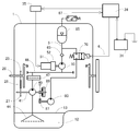
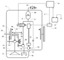
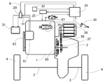
- FIG. 1 is an operation system diagram of a hydraulic starter using an internal combustion engine according to an embodiment of the present invention.
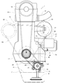
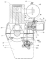
- Example 1 FIG. 2 is a front view of the internal combustion engine as viewed from the direction of the rotation axis.
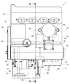
- Example 1 FIG. 3 is a side view of the internal combustion engine as viewed from the intake port side.
- Example 1 4 is a sectional view taken along line XX in FIG.
- Example 1 FIG. 5 is an enlarged local sectional view of the hydraulic motor portion of FIG.
- Example 1 FIG. 6 is an enlarged view of a portion excluding the unit cover of FIG.
- Example 1 7 is a cross-sectional view taken along the line YY of FIG.
- Example 1 is an enlarged ZZ cross-sectional view of FIG.
- FIG. 9 is a schematic diagram of an electric system of a drive unit of a vehicle with an idle stop device using the hydraulic starter of FIG.
- Example 1 FIG. 10 is an operation system diagram of a hydraulic starter using an internal combustion engine according to another embodiment of the present invention.
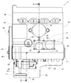
- FIG. 11 is a side view of the internal combustion engine as viewed from the intake port side.
- FIG. 12 is a WW sectional view of FIG.
- FIG. 13 is an operation system diagram of an electric system of a drive unit of a vehicle with an idle stop device using the hydraulic starter of FIG. (Example 2)
- FIG. 14 is a side view of an internal combustion engine according to another embodiment of the present invention as viewed from the intake port side.
- Example 3 FIG.
- FIG. 15 is an operation system diagram of an electric system of a drive unit of a hybrid vehicle equipped with the hydraulic starter of FIG. (Example 4)
- FIG. 16 is an operation system diagram of an electric system of a drive unit of a hybrid vehicle of another embodiment equipped with the same hydraulic starter.
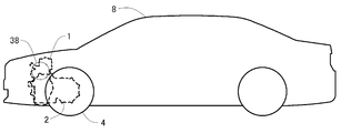
- FIG. 17 is a side view of a vehicle according to an embodiment equipped with an internal combustion engine according to the present invention. (Example 6)
- FIG. 1 is a system diagram in a case where components of a hydraulic starter attached to an internal combustion engine are used as a restart device of an idle stop device according to one embodiment of the present invention.
- a solid line indicates an oil path
- a dotted line indicates a gas path
- a thin line indicates an electric signal line.
- the high-pressure pump 50 is placed downstream of the lubricating oil pump 40 of the internal combustion engine, and the oil strainer 44 and the oil filter 47 are shared. Different points are used. By adopting such a configuration, a constant lubricating pressure is applied to the suction port of the high-pressure pump 50.
- a pressure sensor 67 is adopted instead of the pressure switch.
- the pressure sensor 67 includes a pressure switch that switches a voltage at a constant pressure, and includes a sensor and a switch that detect a gas volume or an oil amount inside the accumulator that indirectly senses the pressure.
- the pressure sensor 67 detects the gas pressure of the accumulator 65, and a signal is sent to the ECU 34.
- the relay 35 of the pump drive motor is energized and mounted on the internal combustion engine 1. The pump drive motor 51 thus rotated is rotated.
- the start of the internal combustion engine is controlled by the ECU 34. Please refer to FIG. 9 and FIG. 15 together.
- the ECU 34 senses the state of the battery in the case of a hybrid vehicle if it is a normal vehicle, and further senses the state of the battery, and energizes the electromagnetic valve 70 attached to the internal combustion engine to hydraulically supply high-pressure oil from the accumulator 65. Supply to motor 80.
- the hydraulic motor 80 supplied with the high-pressure oil rotates, the rotation is decelerated by the speed reduction mechanism 87, and the lubricating oil pump shaft 41 is rotated via the one-way clutch 89. From there, the speed is further reduced through a chain 26 which is a power transmission mechanism of the lubricating oil pump, the crankshaft 20 is driven, and the internal combustion engine 1 is started.
- FIG. 2 is a front view of the four-cycle four-cylinder internal combustion engine 1 equipped with the starting hydraulic motor according to the present embodiment as seen from the direction of the rotation axis.
- the oil pan 11 and the oil surface 13 are indicated by a two-dot chain line.
- the ACG 91, the air conditioner compressor 92, and the belt 93 for driving them are also indicated by a two-dot chain line.
- the crankshaft 20 is supported by being sandwiched between the cylinder block 15 and the crankcase 17.
- the lubricating oil pump 40 is attached to the crankcase 17 from below.
- the crankshaft 20 includes a drive sprocket 25 that drives the lubricating oil pump shaft 41 at an increased speed via a driven sprocket 27 and a chain 26.
- the lubricating oil pump 40 sucks oil from the oil strainer 44 and supplies the oil to the vertical oil passage 45.
- the vertical oil passage 45 is connected to the horizontal oil passage 46 in the crankcase 17, and feeds lubricating oil to the oil filter 47 at the tip of the horizontal oil passage 46.
- the oil that has passed through the oil filter 47 returns again into the crankcase 17 and is sent to the main gallery 48.
- FIG. 3 is a side view of the intake side of the internal combustion engine of FIG.
- the oil filter and intake pipe are omitted.
- a main gallery 48 indicated by a dotted line substantially crosses the internal combustion engine 1 and lubricates each part of the internal combustion engine 1 through the main gallery 48.
- a high-pressure pump and a solenoid valve are integrally formed in a unit 53 described later, and a pump driving motor 51 and a solenoid 78 are attached to a unit cover 77.
- the hydraulic motor 80 is attached to and integrated with the lubricating oil pump 40 via a joint case 82. As described above, the hydraulic motor 80 and the lubricating oil pump 40 can be assembled to the crankcase 17 from below as an integral part, and are placed in the oil chamber 10. After the assembly, the oil pan 11 can be attached from the bottom as in the conventional internal combustion engine.
- FIG. 4 is a sectional view taken along line XX in FIG.
- the accumulator 65 is not in cross section and is omitted from the cylinder head.
- An oil supply oil passage 59 from the main gallery 48 to the high pressure pump is supplied with oil.
- the accumulator 65 is fixed to the outer wall of the cylinder block 15 of the internal combustion engine so as to be removable from the outside.
- the high pressure oil in the accumulator 65 is supplied to the unit cover 77 through the high pressure oil pipe 66 and is supplied to the hydraulic pressure supply valve 71 side through the high pressure oil passage 61.
- the high-pressure oil sent to the hydraulic supply valve 71 is sent to the main valve 73 of the hydraulic supply valve 71 through the high-pressure oil passage 61 of the hydraulic supply valve 71 and supplied to the ball-shaped primary valve 72 through the hole inside the main valve 73. ing.
- the solenoid 78 When the solenoid 78 is energized, the rod protrudes from the solenoid 78 and moves the primary valve 72 to the left from the position shown in the figure. Then, the pressure on the back surface of the main valve 73 decreases, the main valve 73 moves to the right, the valve opens, and high-pressure oil passes through the motor drive oil pipe 75 constituted by a pipe and is sent to the hydraulic motor 80.
- FIG. 5 is an enlarged local sectional view of the hydraulic motor 80 portion of FIG.
- the hydraulic motor 80 is a fixed swash plate type having five pistons 84 in its motor housing 85, and a swash plate bearing 83 presses the piston pushed rightward by hydraulic pressure.
- the total stroke volume of the piston is 8 cc, the hydraulic motor 80 rotates up to 3000 rpm, and the output at that time exceeds 10 KW.
- the hydraulic motor shaft 81 of the hydraulic motor 80 and the lubricating oil pump shaft 41 of the lubricating oil pump 40 are arranged on the same axis, and the speed reduction mechanism is constituted by a planetary gear 88.
- the joint case 82 is integrally formed with a planetary gear ring gear 88R.
- the sun gear 88S provided integrally therewith rotates
- the carrier 88C rotates at a reduced speed in the same direction
- the inner ring 90 of the one-way clutch 89 integrated therewith rotates.
- a sprag type clutch 89 is used as the one-way clutch 89.
- the sprag When the outer ring is stopped, the sprag is tilted in a direction in which the sprag is engaged by a spring force and pressed against both the inner ring and the outer ring.
- the hydraulic motor rotates and the inner ring 90 rotates, the sprags mesh with each other, and the inner ring 90 rotates integrally with the outer ring 41b.
- the outer ring 41b is formed integrally with the lubricating oil pump shaft 41, and the lubricating oil pump shaft 41 further drives the crankshaft 20 from the dribbling rocket 27 via the chain 26 to start the internal combustion engine.
- the hydraulic motor shaft 81 rotates at 3000 rpm
- the crankshaft 20 rotates at 600 rpm.
- the hydraulic motor 80 stops. However, the disengagement of the sprags of the one-way clutch 89 causes the one-way clutch 89 to rotate relative to the inner ring 90 and the outer ring 41b.
- the shaft 20 can continue to rotate.
- the sprag of the one-way clutch 89 of this embodiment rotates together with the outer ring 41b, tilts in a direction that disengages due to centrifugal force, cancels the spring force, and the friction between the sprag and the inner ring 90 occurs. decrease.
- FIG. 6 is a partially enlarged view showing a state in which the unit cover 77 portion of FIG. 3 is enlarged and the pump driving motor 51, the solenoid 78, and the unit cover 77 are omitted.
- a housing of the high pressure pump 50 and a housing of the hydraulic pressure supply valve 71 are integrally formed.
- the internal combustion engine is supplied with lubricating oil to each part, and the lubricating oil returns to the oil pan by its own weight.
- the hydraulic components such as the check valves 62 and 63, the hydraulic supply valve 71 and the high pressure pump 50 are It is in a space communicating with the oil chamber 10 through the return hole 9. Therefore, even if oil is discharged from these parts, the oil returns to the oil pan by its own weight.
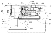
- FIG. 7 shows a YY partial cross-sectional view of the high-pressure pump portion of FIG.
- the speed reduction mechanism 52 in the unit cover 77 is shown in section, and the pump driving motor 51 is shown in non-section.
- An alternate long and short dash line indicates the shape of the front side of the unit 53.
- the unit 53 is attached to the cylinder block 15 together with the unit cover 77 in a state where the unit 53 is fastened to the unit cover 77 with a bolt from the left.
- the inside of the reduction gear 52 is not lubricated, and there is a mysterious gear reduction mechanism having a reduction ratio of about 80 to 1.
- the right ring gear 52R1 is fixed to a unit cover 77 constituting the housing of the speed reducer 52, and the left ring gear 52R2 is integrated with the high pressure pump shaft 54.
- the pump driving motor 51 rotates the sun gear 52S at 8000 rpm
- the free carrier 52C rotates at about 2700 rpm
- the high-pressure pump shaft 54 rotates at about 100 rpm.
- FIG. 8 shows an enlarged ZZ cross-sectional view of the unit 53 of FIG.
- the high-pressure pump 50 is a plunger type pump. As shown in FIG. 7, two cams 54 a and 54 b are integrally provided on the high-pressure pump shaft 54 to move different plungers 55. Each plunger 55 is pushed by a spring 58 and swings to the left and right following the movement of the cam 54a with the rocker arm 57 interposed therebetween.
- the oil passage connected to the plunger 55 is provided with a suction side check valve 62 and a discharge side check valve 63 that prevent backflow of oil, and when the plunger 55 swings, the supply oil passage 59 changes to the high pressure oil passage 61. Feed oil.
- each plunger 55 is provided with a hydraulic seal 56.
- the two cams 54a and 54b are set so that the inclination on the climbing side is moderate, and by changing the phase by 180 °, the oil discharge of each plunger is continued and the driving torque of the high-pressure pump shaft 54 becomes smooth. Yes. Since the stroke volume of each plunger 55 is about 1 cc, the high-pressure pump 50 can be filled with 30 cc of oil for one engine start in 15 rotations, that is, about 9 seconds.
- FIG. 9 is an operation system diagram of an electric system of a vehicle drive unit equipped with the internal combustion engine of this embodiment and having an idle stop function.
- the driving force is transmitted from the transmission 2 to the left and right drive wheels 4 via the left and right axles 3.
- the ECU 34 enters a stop operation of the internal combustion engine 1.
- the supply of fuel to the internal combustion engine 1 is stopped, the throttle valve is slightly opened reversely, and the cam is switched to open the intake valve at the beginning of the expansion stroke.
- the switching unit 29 changes the load of the ACG 91 from the battery 31 to an electric resistance, lowers the terminal voltage, increases the load torque of the ACG 91, and applies the load of the air conditioner compressor regardless of necessity. By these operations, the friction of the internal combustion engine is increased and the internal combustion engine is quickly stopped.
- the operation of the hydraulic starter is the same as in FIG.
- the ECU 34 energizes the electromagnetic valve 70 and restarts the internal combustion engine 1.
- the vehicle is started using the clutch 36 or the torque converter provided with the starting function in the transmission 2 by the driving force of the internal combustion engine 1.
- a conventional electric starter 39 is also provided.
- the electric starter relay 33 is operated by the key switch 32, the electric starter 39 is energized, and the internal combustion engine 1 is once started. Thereafter, if the ECU 34 determines from the warm-up state of the internal combustion engine 1 and the like and determines that idling is not necessary, the internal combustion engine is stopped.
- FIG. 10 is a control system diagram in the case where the components of the hydraulic starting device attached to the internal combustion engine of another embodiment are used as the restarting device of the idle stop device.
- a system for stopping the internal combustion engine 1 earlier is the same as that of the first embodiment of FIG.
- the high-pressure pump 50 is not located downstream of the lubrication pump but has a dedicated oil filter 60 and directly sucks oil in the oil chamber.
- the relay 35 when there is no oil in the accumulator, the relay 35 is first energized, the pump driving motor is turned on, and the accumulator is filled with a certain amount or more of oil by a high-pressure pump to start the internal combustion engine 1. I can do it.
- the conventional electric starter can be omitted.
- the battery 31 does not require a large current like an electric starter, and only needs to be able to fill the hydraulic pressure for starting once in about 9 seconds. Therefore, the battery 31 may have a lower maximum output than a battery equipped with an electric starter, and is compact. There is an advantage that a longer life and longer life can be achieved.
- FIG. 11 is a side view of the internal combustion engine showing how the high-pressure pump 50, the speed reducer 52, and the pump driving motor 51 are attached.
- FIG. 12 is a WW sectional view of FIG. Above the cylinder head is omitted.
- the high-pressure pump 50 is combined with the speed reducer 52 and attached to the crankcase 17 in the vicinity of the oil level 13 from below. After the high-pressure pump 50 is attached, the oil pan 11 can be attached from the bottom in the same manner as a normal internal combustion engine. By attaching the rotary shaft of the high-pressure pump vertically, the pump driving motor 51 can be attached and detached from the outside of the internal combustion engine with the oil pan 11 assembled.
- FIG. 13 is an operation system diagram of an electric system of a vehicle drive unit equipped with the internal combustion engine of this embodiment and having an idle stop function.
- the ECU 34 determines that it is not necessary to start the internal combustion engine 1 according to the state of the vehicle at that time, for example, the state of the accelerator 30 or the warm-up state of the internal combustion engine. Does not start. If it is determined that it is necessary to start the internal combustion engine 1 according to the state of the vehicle, the electromagnetic valve 70 is energized, high pressure oil is supplied to the hydraulic motor, and the internal combustion engine 1 is started.
- FIG. 14 is a side view of an internal combustion engine according to another embodiment, showing a state in which the high pressure pump 50 and the pump driving motor 51 are attached.
- the high pressure pump 50, the speed reducer 52, and the pump driving motor 51 are combined with each other from the bottom with respect to the crankcase 17.
- the oil pan 11 can be attached from below after the high-pressure pump 50 is attached. This arrangement is advantageous when there is no space on the wall of the internal combustion engine, such as in the case of a V-type 6 cylinder.
- the reason why the conventional electric starter can be omitted and the vehicle system having an idle stop function using the internal combustion engine are the same as those in FIG.
- FIG. 15 is an operation system diagram of the electric system of the drive unit of the hybrid vehicle equipped with the hydraulic starter of FIG.
- the reason why the conventional electric starter 39 can be omitted and the operation of the idle stop device are the same as those in the second embodiment.
- the ECU 34 energizes the electromagnetic valve 70 to start the internal combustion engine 1 when it is determined necessary according to the state of the vehicle at that time, but does not start when it is determined that it is not necessary. Is the same as in the second embodiment, but in this embodiment, the state of charge of the hybrid battery is also a determining factor.
- the input shaft of the transmission 2 can be rotated only by the traveling electric motor 38, and the vehicle can start and travel.
- the damper 95 is integrated with the flywheel of the internal combustion engine as in the prior art.
- a one-way clutch 37 is provided inside the rotor of the traveling electric motor 38, and lubricating oil is supplied from the transmission 2. When the internal combustion engine 1 starts and the rotation catches up with the electric motor 38, the electric motor 38 reduces the torque corresponding to the driving force of the internal combustion engine and alleviates the combined shock of the one-way clutch 37.
- the crankshaft according to this embodiment has a rotational inertia mass that is about half that of a crankshaft of a normal internal combustion engine.
- the hydraulic motor is 3000 rpm
- the reduction ratio from the hydraulic motor is lowered so that the crankshaft is 1000 rpm. Yes.
- the necessary electric starter 39 is omitted from the drawing.
- the electric starter relay is actuated by a key switch at the time of activation, the electric starter is energized to once activate the internal combustion engine 1, and the ECU 34 makes a judgment based on the warm-up state of the internal combustion engine 1, etc., and stops the internal combustion engine.
- FIG. 16 is an operation system diagram of an electric system of a drive unit of a hybrid vehicle according to another embodiment.
- the internal combustion engine is the same in both the internal combustion engine of the second embodiment and the internal combustion engine of the third embodiment.
- the chain mechanism 98 and the one-way clutch 37 are supplied with lubricating oil from the transmission 2.
- the driving electric motor 38 is fixed to the upper part of the transmission 2, and the system is other than driving the input shaft of the transmission 2 from the output shaft of the driving electric motor 38 via the chain mechanism 98 as a speed reduction mechanism.
- the configuration and function are the same as in the fourth embodiment.
- the necessary electric starter 39 is omitted from the drawing.
- the electric starter relay is actuated by a key switch at the time of activation, the electric starter is energized to once activate the internal combustion engine 1, and the ECU 34 makes a judgment based on the warm-up state of the internal combustion engine 1, etc., and stops the internal combustion engine.
- FIG. 17 is a side view of a vehicle according to an embodiment equipped with an internal combustion engine according to the present invention. This figure is a side view of a vehicle using any of the drive units of FIGS. 9, 13, 15, and 16. FIG. In the case of a vehicle using the drive unit of FIG. 16, the traveling electric motor 38 is present at the position indicated by the two-dot chain line.
- an internal combustion engine including components constituting the hydraulic starter while suppressing expansion in the rotation axis direction.
- a vehicle having an idle stop device having the same size as a conventional vehicle and a short start time can be obtained.
- a one-motor hybrid vehicle having the same size as a conventional vehicle and capable of stopping the rotation of the internal combustion engine when traveling can be obtained.
Landscapes
- Engineering & Computer Science (AREA)
- Chemical & Material Sciences (AREA)
- Combustion & Propulsion (AREA)
- Mechanical Engineering (AREA)
- General Engineering & Computer Science (AREA)
- Output Control And Ontrol Of Special Type Engine (AREA)
- Control Of Vehicle Engines Or Engines For Specific Uses (AREA)
- Hybrid Electric Vehicles (AREA)
Abstract
Jusqu'à présent, les appareils de démarrage hydraulique n'ont pas été utilisés dans des véhicules en raison des problèmes d'installation qui surviennent du fait que les parties composantes de ceux-ci sont trop grandes pour s'adapter à un moteur à combustion interne en tant qu'élément auxiliaire intégré. Le mécanisme d'entraînement de cet appareil de démarrage hydraulique transmet une force motrice en provenance de l'arbre de sortie d'un moteur hydraulique jusqu'à un mécanisme de réduction par le biais d'une roue libre et de l'arbre de transmission d'une pompe à huile de graissage dans cet ordre, et entraîne le vilebrequin d'un moteur à combustion interne en provenance de l'arbre de transmission en utilisant le mécanisme de transmission de puissance de la pompe à huile de graissage. Par conséquent, la détente dans la direction de l'arbre du moteur à combustion interne est éliminée et le bruit provenant du mécanisme d'entraînement est supprimé. Par ailleurs, les problèmes d'installation sont résolus par l'arrangement des pièces constitutives hydrauliques de l'appareil de démarrage hydraulique de manière répartie dans la chambre à huile du moteur à combustion interne ou un endroit en communication avec celui-ci. En utilisant ce moteur à combustion interne, il est possible de mettre en œuvre des véhicules équipés d'un dispositif de réduction de ralenti ayant un temps de démarrage court et des véhicules hybrides à un moteur en mesure d'arrêter la révolution de la combustion interne lors du déplacement, et similaires, dont la taille est identique à celle des véhicules traditionnels.
Applications Claiming Priority (2)
| Application Number | Priority Date | Filing Date | Title |
|---|---|---|---|
| JP2011-240814 | 2011-11-02 | ||
| JP2011240814 | 2011-11-02 |
Publications (1)
| Publication Number | Publication Date |
|---|---|
| WO2012169663A1 true WO2012169663A1 (fr) | 2012-12-13 |
Family
ID=47296208
Family Applications (1)
| Application Number | Title | Priority Date | Filing Date |
|---|---|---|---|
| PCT/JP2012/070731 Ceased WO2012169663A1 (fr) | 2011-11-02 | 2012-08-15 | Véhicule équipé d'un appareil de démarrage hydraulique |
Country Status (1)
| Country | Link |
|---|---|
| WO (1) | WO2012169663A1 (fr) |
Cited By (2)
| Publication number | Priority date | Publication date | Assignee | Title |
|---|---|---|---|---|
| US9598103B1 (en) | 2013-12-20 | 2017-03-21 | Hydro-Gear Limited Partnership | Steerable transaxle |
| US9726269B1 (en) | 2009-07-24 | 2017-08-08 | Hydro-Gear Limited Partnership | Transmission and engine configuration |
Citations (8)
| Publication number | Priority date | Publication date | Assignee | Title |
|---|---|---|---|---|
| JPS4869921A (fr) * | 1971-12-28 | 1973-09-22 | ||
| JPH03262726A (ja) * | 1990-03-12 | 1991-11-22 | Nissan Motor Co Ltd | パワープラント構造 |
| JP2002339840A (ja) * | 2001-05-15 | 2002-11-27 | Honda Motor Co Ltd | 車両の油圧式エンジン始動装置 |
| JP2004129469A (ja) * | 2002-10-07 | 2004-04-22 | Fuji Heavy Ind Ltd | ハイブリット車の動力伝達装置 |
| JP2004324448A (ja) * | 2003-04-22 | 2004-11-18 | Toyota Motor Corp | 車両用エンジンの始動装置 |
| JP2007224737A (ja) * | 2006-02-21 | 2007-09-06 | Toyota Central Res & Dev Lab Inc | エンジン始動装置 |
| JP2007315338A (ja) * | 2006-05-29 | 2007-12-06 | Toyota Central Res & Dev Lab Inc | エンジン始動装置 |
| JP2008105622A (ja) * | 2006-10-27 | 2008-05-08 | Toyota Central R&D Labs Inc | ハイブリッド車両の駆動装置 |
-
2012
- 2012-08-15 WO PCT/JP2012/070731 patent/WO2012169663A1/fr not_active Ceased
Patent Citations (8)
| Publication number | Priority date | Publication date | Assignee | Title |
|---|---|---|---|---|
| JPS4869921A (fr) * | 1971-12-28 | 1973-09-22 | ||
| JPH03262726A (ja) * | 1990-03-12 | 1991-11-22 | Nissan Motor Co Ltd | パワープラント構造 |
| JP2002339840A (ja) * | 2001-05-15 | 2002-11-27 | Honda Motor Co Ltd | 車両の油圧式エンジン始動装置 |
| JP2004129469A (ja) * | 2002-10-07 | 2004-04-22 | Fuji Heavy Ind Ltd | ハイブリット車の動力伝達装置 |
| JP2004324448A (ja) * | 2003-04-22 | 2004-11-18 | Toyota Motor Corp | 車両用エンジンの始動装置 |
| JP2007224737A (ja) * | 2006-02-21 | 2007-09-06 | Toyota Central Res & Dev Lab Inc | エンジン始動装置 |
| JP2007315338A (ja) * | 2006-05-29 | 2007-12-06 | Toyota Central Res & Dev Lab Inc | エンジン始動装置 |
| JP2008105622A (ja) * | 2006-10-27 | 2008-05-08 | Toyota Central R&D Labs Inc | ハイブリッド車両の駆動装置 |
Cited By (4)
| Publication number | Priority date | Publication date | Assignee | Title |
|---|---|---|---|---|
| US9726269B1 (en) | 2009-07-24 | 2017-08-08 | Hydro-Gear Limited Partnership | Transmission and engine configuration |
| US10364874B1 (en) | 2009-07-24 | 2019-07-30 | Hydro-Gear Limited Partnership | Transmission and engine configuration |
| US9598103B1 (en) | 2013-12-20 | 2017-03-21 | Hydro-Gear Limited Partnership | Steerable transaxle |
| US10337608B1 (en) | 2013-12-20 | 2019-07-02 | Hydro-Gear Limited Partnership | Steerable transaxle |
Similar Documents
| Publication | Publication Date | Title |
|---|---|---|
| KR100898346B1 (ko) | 내연기관용 제어장치 및 상기 제어장치를 구비한 자동차 | |
| US10730387B2 (en) | Drive device for a hybrid-powered motor vehicle | |
| JP5910211B2 (ja) | 車両搭載エンジンの始動装置 | |
| CN100400830C (zh) | 具有带压缩比可变机构的内燃机的动力装置 | |
| EP1321646B1 (fr) | Moteur à combustion interne | |
| JP2002307956A (ja) | 車両用駆動装置 | |
| WO2007111800A2 (fr) | Moteur a deux temps hybride monocylindrique, compresseur et pompe et procede de fonctionnement | |
| CN101890902A (zh) | 混合动力推进系统的串列式双泵 | |
| US5398508A (en) | Three displacement engine and transmission systems for motor vehicles | |
| EP1321645B1 (fr) | Moteur à combustion interne | |
| US7373870B2 (en) | Universal hybrid engine, compressor and pump, and method of operation | |
| WO2012169663A1 (fr) | Véhicule équipé d'un appareil de démarrage hydraulique | |
| JP5255618B2 (ja) | 内燃機関の始動方法 | |
| US20110121571A1 (en) | Torque transmitting mechanism of an internal combustion engine, a vehicle and a method of transmitting torque | |
| EP2093415A2 (fr) | Appareil de transmission de couple pour transmettre un couple de commande depuis un démarreur de moteur vers un moteur à combustion interne | |
| US7757800B2 (en) | Monocylindrical hybrid powertrain and method of operation | |
| JP3644337B2 (ja) | 内燃機関の補機配設構造 | |
| JPH07255104A (ja) | ハイブリッド型電気自動車 | |
| JP2000230430A (ja) | 内燃機関の遊星歯車機構 | |
| RU213744U1 (ru) | Компактный компрессорный агрегат | |
| JPH0771216A (ja) | エンジンの潤滑装置 | |
| KR101288033B1 (ko) | 이중 크랭크 축 엔진 | |
| JP2001289022A (ja) | 内燃機関の潤滑装置 | |
| JP2025133525A (ja) | ハイブリッド車両 | |
| JP5886175B2 (ja) | 流体圧アシスト車両のエンジン始動制御装置 |
Legal Events
| Date | Code | Title | Description |
|---|---|---|---|
| 121 | Ep: the epo has been informed by wipo that ep was designated in this application |
Ref document number: 12796536 Country of ref document: EP Kind code of ref document: A1 |
|
| NENP | Non-entry into the national phase |
Ref country code: DE |
|
| 122 | Ep: pct application non-entry in european phase |
Ref document number: 12796536 Country of ref document: EP Kind code of ref document: A1 |
|
| NENP | Non-entry into the national phase |
Ref country code: JP |