WO2012169669A1 - Dispositif élastique et mécanisme pour commander un déplacement horizontal à l'aide d'une composante horizontale de force élastique, et appareil d'appui l'utilisant - Google Patents
Dispositif élastique et mécanisme pour commander un déplacement horizontal à l'aide d'une composante horizontale de force élastique, et appareil d'appui l'utilisant Download PDFInfo
- Publication number
- WO2012169669A1 WO2012169669A1 PCT/KR2011/004164 KR2011004164W WO2012169669A1 WO 2012169669 A1 WO2012169669 A1 WO 2012169669A1 KR 2011004164 W KR2011004164 W KR 2011004164W WO 2012169669 A1 WO2012169669 A1 WO 2012169669A1
- Authority
- WO
- WIPO (PCT)
- Prior art keywords
- tilted
- elastic
- tilted surface
- guiding
- bridge bearing
- Prior art date
- Legal status (The legal status is an assumption and is not a legal conclusion. Google has not performed a legal analysis and makes no representation as to the accuracy of the status listed.)
- Ceased
Links
Images




Classifications
-
- F—MECHANICAL ENGINEERING; LIGHTING; HEATING; WEAPONS; BLASTING
- F16—ENGINEERING ELEMENTS AND UNITS; GENERAL MEASURES FOR PRODUCING AND MAINTAINING EFFECTIVE FUNCTIONING OF MACHINES OR INSTALLATIONS; THERMAL INSULATION IN GENERAL
- F16F—SPRINGS; SHOCK-ABSORBERS; MEANS FOR DAMPING VIBRATION
- F16F15/00—Suppression of vibrations in systems; Means or arrangements for avoiding or reducing out-of-balance forces, e.g. due to motion
- F16F15/02—Suppression of vibrations of non-rotating, e.g. reciprocating systems; Suppression of vibrations of rotating systems by use of members not moving with the rotating systems
- F16F15/04—Suppression of vibrations of non-rotating, e.g. reciprocating systems; Suppression of vibrations of rotating systems by use of members not moving with the rotating systems using elastic means
- F16F15/043—Suppression of vibrations of non-rotating, e.g. reciprocating systems; Suppression of vibrations of rotating systems by use of members not moving with the rotating systems using elastic means acting on a cam follower
-
- E—FIXED CONSTRUCTIONS
- E01—CONSTRUCTION OF ROADS, RAILWAYS, OR BRIDGES
- E01D—CONSTRUCTION OF BRIDGES, ELEVATED ROADWAYS OR VIADUCTS; ASSEMBLY OF BRIDGES
- E01D19/00—Structural or constructional details of bridges
- E01D19/04—Bearings; Hinges
-
- F—MECHANICAL ENGINEERING; LIGHTING; HEATING; WEAPONS; BLASTING
- F16—ENGINEERING ELEMENTS AND UNITS; GENERAL MEASURES FOR PRODUCING AND MAINTAINING EFFECTIVE FUNCTIONING OF MACHINES OR INSTALLATIONS; THERMAL INSULATION IN GENERAL
- F16F—SPRINGS; SHOCK-ABSORBERS; MEANS FOR DAMPING VIBRATION
- F16F15/00—Suppression of vibrations in systems; Means or arrangements for avoiding or reducing out-of-balance forces, e.g. due to motion
- F16F15/02—Suppression of vibrations of non-rotating, e.g. reciprocating systems; Suppression of vibrations of rotating systems by use of members not moving with the rotating systems
- F16F15/04—Suppression of vibrations of non-rotating, e.g. reciprocating systems; Suppression of vibrations of rotating systems by use of members not moving with the rotating systems using elastic means
- F16F15/08—Suppression of vibrations of non-rotating, e.g. reciprocating systems; Suppression of vibrations of rotating systems by use of members not moving with the rotating systems using elastic means with rubber springs ; with springs made of rubber and metal
Definitions
- the present invention relates to an elastic device, a mechanism for controlling horizontal displacement, and a bridge bearing, which are adapted for bridges.
- a conventional bridge bearing related to the present invention installs a MER (mass energy regulator) spring allowing a big displacement horizontally between a component fixed to a bridge pier and another component fixed to a top structure of bridge, so as to absorb external force by earthquake, wind, braking of car, a thermal deformation or vibration in a direction of bridge axis, etc.
- MER mass energy regulator
- the inventor of present invention found followings problems in a traditional bridge bearing.
- the length of the MER spring in traditional bridge bearing increases in proportion to the length of an allowed contraction displacement.
- the MER spring is installed on both sides of the bridge bearings generally.
- An objective of the present invention is to provide a bridge bearing, which provides a larger allowed horizontal displacement than conventional bridge bearings using an elastic means such as a MER spring that is shorter than the MER spring of the conventional bridge bearing.
- Another objective of the present invention is to provide a bridge bearing, which can easily control the magnitude of the resistance against a horizontal displacement.
- Still another objective of the present invention is to provide a bridge bearing, which reduces the length of the elastic means such as a MER spring drastically.
- Still another objective of the present invention is to provide a bridge bearing, which reduces the height compared to the conventional bridge bearing.
- Still another objective of the present invention is to provide a mechanism for controlling horizontal displacement, which can be used for making the bridge bearing suitably.
- Still another objective of the present invention is to provide an elastic device, which can be used for making the horizontal displacement controlling mechanism and the bridge bearing suitably.
- a bridge bearing according to the present invention comprises: a bottom member installed on a bridge pier; a top member installed on a bottom surface of a top structure supported by the bridge pier; and a weight-support portion, which is disposed between the bottom member and the top member so as to support the weight of the top structure on the bridge piers and allow the top member to move relative to the bottom member in at least one horizontal direction, further comprising: a tilted surface installed in at least one of the top member, the bottom member, and the weight-support portion; and an elastic means installed elastically in at least one of the other of the top member, the bottom member, and the weight-support portion facing the tilted surface, which is pressed by the tilted surface at least in a part of segment of the relative movement and exerts an elastic recovering force to the tilted surface, so as to have a horizontal component of the elastic recovering force act as a force for moving one of the above elements horizontally.
- the tilted surface is installed one of the top member and the bottom member, and disposed to be tilted with respect to the moving direction of the other of the top member and the bottom member, and
- the elastic means may be installed elastically at the other of the top member and the bottom member facing the tilted surface.
- the horizontal component of the elastic recovering force acting in a direction of horizontal movement of the top member is preferably exerted as a force for a relative movement of the top member in a direction horizontal to the top member.
- the elastic means preferably comprises: an elastic body; an axle member engaging the elastic body and guiding the elastic body to extend and contract toward the tilted surface; and a tilted-surface contacting end portion engaging an end portion of the axle member, preventing the elastic body from disengaging, and slide-contacting the tilted surface.
- a guide portion disposed along around the elastic means for guiding a movement of the tilted end portion.
- the tilted surface and the elastic means are installed facing each other up and down, and the tilted surface preferably includes parts disposed symmetrically right to left, front to rear, or right to left and front to rear, and higher and higher or lower and lower as approaching the center.
- the tilted surface and the elastic means are installed facing each other horizontally, and the tilted surface preferably includes parts disposed symmetrically right to left, front to rear, or right to left and front to rear, and convex toward the outside or inside as approaching the center.
- guiding portions are installed with an interval on the bottom member or the top member for guiding the weight-support portion to move in a horizontal direction.
- the tilted surface may be installed on both sides of the weight-support portion with an interval.
- the weight-support portion comprises a bottom slide member guided by the first guiding portion, a top slide member guided by the second guiding portion, and a middle member disposed between the bottom slide member and the top slide member and having a portion protruding sideways more than the bottom slide member and the top slide member; and the tilted surface and the elastic means are installed in positions facing the bottom member and the bottom surface of the middle member respectively and in positions facing the top member and the top surfaces of the middle member respectively.
- a first guiding portion for guiding a horizontal movement of the weight-support portion in the first horizontal direction
- the second guiding portion for guiding the movement of the weight-support portion in a second horizontal direction crossing the first horizontal direction when viewing from a top side
- the weight-support portion includes a bottom slide member guided by the first guiding portion and a top slide member guided by the second guiding portion,
- the tilted surface and the elastic means are installed in positions where the top surface of the first guiding portion and the top slide member face each other respectively, and may be installed in positions where the bottom surface of the second guiding portion and the bottom slide member face each other respectively.
- the elastic means may include an elastic body, and an axle member engaged to the elastic body and guiding the elastic body to extend and contract toward the tilted surface, and a tilted-surface contact end portion engaged to the axle member, preventing the elastic body from disengaging, and including a spherical body installed rotatably in a spherical groove.
- a horizontal displacement control mechanism comprises: a bottom member for installing on a bridge pier; a top member, for installing on a bottom surface of a top structure supported by the bridge pier, which performs a relative movement in at least one horizontal direction with respect to the bottom member; a tilted surface installed in one of the top member and the bottom member; and an elastic means installed in the other one of the top member and the bottom member so as to extend and contract toward the tilted surface, wherein by being compressed by the tilted surface at least in a part of the segment of the relative movement and exerting an elastic recovering force against the tilted surface the horizontal component of the elastic recovering force acts as a force to move any one of the above elements horizontally.
- An elastic device comprises: an elastic body; an axle member penetrating the elastic body and guiding the extension and contraction of the elastic body; a tilted-surface contact end portion installed in an end of the axle member, preventing the elastic body from disengaging from the axle member, and formed with an external surface which is tilted or curved, wherein with respect to the tilted surface contacting an end portion of the tilted-surface contact end portion is exerted an elastic recovering force of the elastic body.
- a bridge bearing according to the invention can move horizontally while keeping the height of the top structure constant, accommodate a large horizontal displacement of the top structure with an elastic body that is much shorter than in prior arts, and can be made with very low height, so that it can be used for railroad bridge as well as general bridge, and especially be used for a large bridge having a large horizontal displacement suitably.
- a bridge bearing according to the invention has an easy preliminary compression since the MER spring is compressed automatically by the weight of the top structure when installing the tilted surface and the elastic means facing each other up and down, absorbs vertical vibration of the top structure, and has resistance to vibration in directions of the bridge axis, perpendicular to the bridge axis, and up and down.
- a double sliding bridge bearing and multiple friction sliding bridge bearing can be realized easily, and it is possible to apply to a disc bearing, spherical bearing, pot bearing, etc.
- the elastic device is a kind of elastic means.
- Fig. 1 is an exploded perspective view showing a bridge bearing having a function of controlling a horizontal displacement using force component of an elastic body according to the invention
- Fig. 2 is an exploded perspective view which is viewed from a bottom surface of the bridge bearing of Fig. 1;
- Fig. 3 is a cross-sectional view showing a state in which the bridge bearing of Fig. 1 is installed;
- Fig. 4 is a cross-sectional view showing a state in which a top member fixed to a top structure moves horizontally generating a horizontal displacement
- Fig. 5 is a cross-sectional view showing a variant of the bridge bearing of Fig. 3;
- Fig. 6 is a cross-sectional view showing another variant of the bridge bearing of Fig. 3;
- Fig. 7 is a front plan view showing a bridge bearing according to another embodiment of the invention.
- Fig. 8 is a longitudinal sectional view showing along I-I of Fig. 7;
- Fig. 9 is a cross-sectional view showing a bridge bearing according to still another embodiment of the invention.
- Fig. 10 is a side plan view of Fig. 9;
- Fig. 11 is a cross-sectional view showing a bridge bearing according to still another embodiment of the invention.
- Fig. 12 is a diagram for explaining an example of installing the bridge bearing in Fig. 11;
- Figs. 13 and 14 are cross-sectional views showing variants of the bridge bearing in Fig. 5;
- Fig. 15 is a perspective view showing a bridge bearing according to still another embodiment of the invention.
- Fig. 16 is a perspective view showing a bridge bearing according to still another embodiment of the invention.
- Fig. 17 is a partial front cross-sectional view showing the bridge bearing of Fig. 16;
- Fig. 18 is a partial side cross-sectional view showing the bridge bearing of Fig. 16;
- Fig. 19 is a plan view showing a layout of bottom member, weight-support portion, and elastic means of the bridge bearing of Fig. 16;
- Fig. 20 is a plan view showing a state in which the weight-support portion of Fig. 19 moves in a horizontal direction;
- Fig. 21 is a partial sectional perspective view showing a bridge bearing according to still another embodiment of the invention.
- Fig. 22 is a right side plan view showing the bridge bearing of Fig. 16;
- Fig. 23 is a front plan view showing a state in which a top member of the bridge bearing of Fig. 16 moves horizontally to the right;
- Fig. 24 is a right side plan view showing a state in which the top member of Fig. 16 moves horizontally relatively forward and to the left with respect to a bottom member of the bridge bearing of Fig. 16.
- Fig. 1 is an exploded perspective view showing a bridge bearing having a function of controlling a horizontal displacement using force component of an elastic body according to the invention
- Fig. 2 is an exploded perspective view which is viewed from a bottom surface of the bridge bearing of Fig. 1
- Fig. 3 is a cross-sectional view showing a state in which the bridge bearing of Fig. 1 is installed
- Fig. 4 is a cross-sectional view showing a state in which a top member fixed to a top structure moves horizontally generating a horizontal displacement.
- a bridge bearing 100 shown in Figs. 1-4 is installed at two-direction moving platform, and comprises a bottom member 110 fixed to the bridge pier 12.
- the bottom member 110 takes a shape of planar plate, and are installed to a bridge pier 12 through anchor nut 14 and bolt 15.
- On a top surface of the bottom member 110 is attached a low-friction material 112 made of stainless steel plate, etc.
- the bridge bearing 100 comprise a top member 130 fixed to a bottom surface of a top structure 18 supported by the bridge pier 12.
- the top member 130 is fixed to the bottom surface of the top structure 18 through welding, etc.
- a tilted surface 132 which is tilted up and down such that the surface gets higher and higher as approaching the center.
- the tilted surface 132 is formed with planes, preferably disposed symmetrically to the right and left with an interval, and disposed symmetrically with an interval front and rear.
- a low-friction material 134 made of stainless steel plate, etc.
- the slope angle of the such a tilted surface 132 may be about 5.7 degrees through 10.0 degrees appropriately, and angles below 5.7 degrees and beyond 10.0 degrees are also possible.
- the tilted surface 132 preferably may be installed in one direction only, right-left or front-rear. Also, the tilted surface 132 is not limited to be installed symmetrically right-left or front-rear. For example, if the top structure 18 is limited to move horizontally only to the left but not to the right in Fig. 3, the left tilted surface 132 and an elastic means 150 acting on the tilted surface 132 are not needed.
- the tilted surface 132 can be installed only in one side.
- the length and the slope angle of the two tilted surfaces 132 in the right-left or the front-rear may be applied differently according to the conditions of the top structure 18 and the bridge pier 12.
- a dislocation-preventing step 136 for preventing the elastic means 150 from getting away from the tilted surface 132.
- the weight-support portion 170 performs a function of supporting the weight of the top structure 18 on the bridge pier 12, and comprises a pin 172 fixed to the top member 130, an elastic body 174 formed of a hard (the hardness is about 45D ⁇ 65D) polyurethane disc engaged to an outer surface of the pin 172, and slide member 176 contacting a low-friction material 112 installed on a top surface of the bottom member 110 and engaging an end portion of the pin 172. On a bottom surface of the slide member 176 is attached a low-friction material 177 including PTFE, etc.
- a groove 178 in which the end portion of the pin 172 is inserted.
- the groove 178 has a cross-sectional area slightly larger than the pin 172 such that the pin 172 can move rotatably to the right and left.
- a pin hole is formed in a center of the top member 130, and the pin 172 is fixed in the slide member 176.
- the elastic means 150 includes an elastic body 152 which can extend and contract toward the tilted surface 132.
- the elastic means 150 preferably comprise an elastic body 152 made of a soft (the hardness range is about 65A ⁇ 100A) polyurethane, an axle member 154 penetrating the elastic body 152, and a tilted-surface contacting end portion 156 that is connected to the end portion of the axle member 154, prevents the elastic body 152 from dislocating from the axle member 154, and contacts the tilted surface 132.
- the elastic body 152 is compressed by the tilted surface 132 in at least a part of segment of relative movement of the bottom member 110 and the top member 130 with respect to each other and exerts an elastic recovering force with respect to the tilted surface 132.
- a horizontal component of the elastic recovering force of the elastic body 152 acts as a force for moving the top member 130 horizontally relatively with respect to the bottom member 110.
- the length of the elastic body 152 of about 25 ⁇ 38mm is sufficient for accommodating a horizontal displacement of ⁇ 100mm. This is one of drastic improvements compared to conventional bridge bearings. More of this is going to be explained later.
- the length of the elastic body 152 can be reduced to about 1/6 to 1/10 compared to the length of elastic body for the conventional bridge bearing.
- the axle member 154 guides the elastic body 152 to extend and contract toward the tilted surface 132, and prevents the elastic body 152 from bending sideways.
- Such an axle member 154 is installed movably up and down in the groove 114 formed in the bottom member 110 so as to accommodate the extension and contraction of the elastic body 152.
- a surface of the tilted-surface contacting end portion 156 is preferably formed tilted so as to surface-contact with the tilted surface 132, and is attached with a low-friction material 158 such as PTFE and the like.
- a guiding portion 159 disposed along around the elastic means 150 for guiding up-and-down movement of the tilted-surface contacting end portion 156.
- the guiding portion 159 supports the tilted-surface contacting end portion 156 and prevents the elastic body 152 and the axle member 154 from bending under lateral force.
- Such a guiding portion 159 preferably has a shape of tube.
- the guiding portion 159 has a diameter a little larger than that of the elastic body 152 so as to accommodate the elastic body 152 which may be compressed to have the diameter increased.
- the elastic means 150 described in the above is a kind of mass energy regulator (MER) spring.
- MER mass energy regulator
- the elastic body made of hard polyurethane disc for supporting vertical weight of the top structure and the elastic body made of soft polyurethane for buffering or recovering a horizontal displacement of the top structure are well known in the art to which the invention pertains and commercially available, and therefore more description is omitted.
- the elastic means 150 are installed at the positions of symmetrical right and left and front and rear corresponding to the four tilted surfaces 132 respectively. In cases, in one tilted surface 132 can be installed two or more elastic means 150.
- the length, etc. for an elastic body for an example of capacity of the bridge bearing of 500 tons and design load DL: 360 tons may be calculated as followings.
- the slope angle ⁇ of about 5.7 ⁇ 10 degrees is appropriate, and as for the length of elastic body for a horizontal displacement of ⁇ 100mm (the tilted surface and the elastic means installed on both locations of right and left or front and rear) about 25 ⁇ 38mm is appropriate.
- the shape factor must be considered.
- the compressed length of the MER spring becomes 10, 20, and 30mm respectively, and the entire length of the MER spring (elastic body) according to them becomes 20, 50, and 70mm respectively.
- the top structure 18 receives a force to the right by earthquake, wind, or car braking, the top structure 18, the top member 130, and the weight-support portion 170 move relative horizontal movement to the right with respect to the bridge pier 12 and the bottom member 110 fixed to the bridge pier 12.
- the weight-support portion 170 moves to the right riding a top surface of the bottom member 110 while supporting the weight of the top structure 18.
- the elastic body 152 of the right elastic means 150 which was compressed by the right tilted surface 132 recovers and expands upward. As the elastic body 152 expands more and more, the horizontal component of the elastic recovering force for moving the top member 130 to the right gets smaller and smaller. If the weight-support portion 170 moves to the right further when the elastic body 152 reached the limit to the expansion, the tilted-surface contacting end portion 156 is detached from the right tilted surface 132.
- the elastic body 152 of the left elastic means 150 is compressed more and more by the left tilted surface 132 as the weight-support portion 170 moves to the right while being compressed by the left tilted surface 132.
- the horizontal component of the elastic recovering force for moving the top member 130 to the left gets larger and larger.
- the top structure 18 and the top member 130 receive a force to the left by the horizontal component of the elastic recovering force exerted to the left tilted surface 132 by the left elastic means 150.
- the top structure 18 and the top member 130 move to the left riding the weight-support portion 170 and stop at a location where the right elastic means 150 is compressed by the right tilted surface 132 in the above to match the horizontal component exerted to the right tilted surface 132.
- the top structure 18 moves to the left by an external force, the top structure 18 recovers to the central position through a process opposite to the above process.
- the bridge bearing 100 of the embodiment is installed on moving platforms in both directions, also in the case that the top structure 18 moves to the front or rear by an external force, the top member 130, the weight-support portion 170, and the top structure 18 are recovered to the central position in a manner same as explained in the above.
- the top structure 18 may be recovered to the central position by cooperation of the elastic means 150 of four directions.
- the limit to the movement to right and left or front and rear is determined by an interval between the slide member 176 and the guiding portion 159 and an interval between the tilted-surface contacting end portion 156 and the dislocation-preventing step 136 respectively.
- the two intervals are preferably same, but may be different, and in cases only one of the guiding portion 159 and the dislocation-preventing step 136 may be installed or none of them may be installed.
- the length of the elastic body 152 of the elastic means 150 used in the bridge bearing 100 of Figs. 1-4 is reduced drastically according to the slope angle of the tilted surface 132 compared to the length of elastic body used in the conventional bridge bearing's elastic means.
- the bridge bearing 100 described so far may be flipped and then used.
- the bottom member 110 in Figs. 1-4 becomes a top member
- the top member 130 becomes a bottom member. This holds true to the embodiments below.
- Fig. 5 is a cross-sectional view showing a variant of the bridge bearing of Fig. 3.
- the tilted surface 132 installed in the top member 130 may be configured to get lower and lower in the height of the tilted surface 132 as going from the edge to the center of the bridge bearing 100, opposite to the previous embodiment.
- the slope direction of the tilted-surface contacting end portion 156 of the elastic means 150 is opposite to the previous embodiment.
- the right elastic means 150 is compressed by the right tilted surface 132, and exerts a force for recovering the top member 130 to the original position.
- the dislocation-preventing step may be omitted.
- the dislocation-preventing step may be installed by making the length of the top member 130 disposed outside the elastic means 150 same to or longer than the inside.
- the pin 172 in this embodiment is fixed to the slide member 176 of the weight-support portion 170, a groove 131 to which an end portion of the pin 172 penetrating the elastic body 174 is inserted is formed in the top member 130.
- Fig. 6 is a cross-sectional view showing another variant of the bridge bearing of Fig. 3.
- the bridge bearing 100 shown in Fig. 6 is similar to the bridge bearing of Fig. 3 which is flipped upside down.
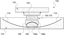
- the tilted surface 116 is formed on a top surface of the bottom member 110, the elastic means 150 is installed flexibly to the top member 130 toward the tilted surface 116. Also, the length of the tilted surface 116 disposed inside the elastic means 150 is shorter than the length of the tilted surface 116 disposed outside the elastic means 150, which is different from the previous embodiment. In such a case, the thickness of the bottom member 110 to which the tilted surface 116 is installed may be reduced more or less.
- Fig. 7 is a front plan view showing a bridge bearing according to another embodiment of the invention
- Fig. 8 is a longitudinal sectional view showing along I-I of Fig. 7.
- the bridge bearing 100 shown in Figs. 7 and 8 is used in a one-direction moving platform.
- the guiding portions 113 prevents the weight-support portion 170 from moving in a direction perpendicular to the bridge axis, and guides to move in a direction of bridge axis.
- a low-friction material 113a such as stainless steel plate and the like is attached to the inside of the guiding portion 113 and the low-friction material 176a such as PTFE and the like is attached to the side surface of the slide member 176, such that the weight-support portion 170 moves freely in the direction of bridge axis.
- Fig. 9 is a cross-sectional view showing a bridge bearing according to still another embodiment of the invention
- Fig. 10 is a side plan view of Fig. 9.
- the bridge bearing 100 shown in Figs. 9 and 10 is used in a one-direction moving platform, the tilted surface 116 is formed on the guiding portion 113, the tilted surface 116 is formed with a curved surface, not with a planar surface, and it has a tilted-surface contacting end portion 156 where the a spherical surface body 156c is installed rotatably to a spherical surface groove 156b by forming the tilted surface 116 with curved surface, which is different from the embodiment of Figs. 7 and 8.
- Fig. 11 is a cross-sectional view showing a bridge bearing according to still another embodiment of the invention
- Fig. 12 is a diagram for explaining an example of installing the bridge bearing in Fig. 11.
- the tilted surface 116 of a spherical shape is formed in the bottom member 110, and the elastic means 150 is installed in the top member 130 as shown in Figs. 8 and 10 flexibly toward the tilted surface 116, so as to realize the bridge bearing 100 according to the invention.
- the elastic means 150 performs a function of the weight-support portion 170, too.
- the elastic means 150 may be limited so as to move horizontally in one direction.
- the bridge bearing 100 shown in Fig. 11 may be used for recovering a horizontal displacement of the top structure 18 installed on around the two-direction moving platform 13.
- the bridge bearing 100 shown in Fig. 11 may be installed around the one-direction moving platform and used for the top structure 18 to recover the one-direction horizontal displacement in a direction of bridge axis.
- the bridge bearing 100 shown in Fig. 11 performs a function of controlling mechanism of the horizontal displacement using the component force of the elastic body.
- Figs. 13 and 14 are cross-sectional views showing variants of the bridge bearing in Fig. 5.
- the weight-support portion 170 can be formed only with the slide member 176 having spherical surface, without an elastic body.
- a contacting surface of the slide member 176 having spherical surface is preferably installed a low-friction material 177 made of PTFE and the like.
- a groove 133 having a spherical shape In the top member 130 in which the slide member 176 having a spherical surface is installed must be formed a groove 133 having a spherical shape.
- the bridge bearing 100 may be formed in a type of a pot bearing. That is, a weight-support portion 170 may be formed by installing the elastic body 174 in a cylindrical groove 133 formed bottom surface of the top member 130 and inserting a top end of a cylindrical slide member 176 at a bottom surface of which the low-friction material 177 is installed.
- Fig. 15 is a perspective view showing a bridge bearing according to still another embodiment of the invention.
- the bridge bearing 100 shown in Fig. 15 may be used in a two-direction moving platform, and includes bottom members 110 in which first guiding portions 115 are installed in parallel on both sides of right and left of the weight-support portion 170 with an interval.
- the first guiding portion 115 allows the weight-support portion 170 to move in a first horizontal direction only such as a direction of bridge axis or a direction perpendicular to the bridge axis, on a top surface of which are formed the tilted surfaces 116 having curved surface respectively.
- the top member 130 are formed second guiding portions 135 in front and in rear on both sides of weight-support portion 170 with an interval in parallel.
- the second guiding portion 135 allows the weight-support portion 170 to move in a second horizontal direction only perpendicular to the first horizontal direction, on the bottom surface of which are formed the tilted surfaces 132 with curved surface respectively.
- the second guiding portion 135 does not have to be disposed in direction perpendicular to the first guiding portion 115 only.
- the second horizontal direction along which the second guiding portion 135 is disposed crosses the first horizontal direction along which the first guiding portion 115 is disposed, when viewing from the above.
- the weight-support portion 170 comprises a bottom slide member 176b guided by the first guiding portion 115, a top slide member 176c guided by the second guiding portion 135, and a middle member 173 inserted between the two bottom and top slide members 176b, 176c and having a portion protruding more than the two bottom and top slide members 176b, 176c.
- the weight-support portion 170 includes an elastic body 174 disposed between the middle member 173 and the bottom slide member 176b.
- a hard polyurethane disc may be used for this elastic body 174.
- the middle member 173 On the bottom surface and the top surface of the middle member 173 are installed elastic means 150 facing the tilted surface 116 installed in the bottom member 110 and the tilted surface 132 installed in the top member 130 respectively.
- the tilted surfaces 116, 132 and the elastic means 150 facing each other at corresponding positions are installed up and down, that is, vertically, and the surface of the tilted-surface contacting end portion 156 contacting with the tilted surfaces 116, 132 are formed with a curvature same as that the tilted surfaces 116, 132.
- the relative horizontal displacement of the top member 130 in the first horizontal direction against the bottom member 110 is recovered by the elastic means 150 installed elastically toward the tilted surface 116 installed in the bottom member 110
- the relative horizontal displacement of the top member 130 in the second horizontal direction against the bottom member 110 is recovered by the elastic means 150 installed elastically toward the tilted surface 132 installed in the top member 130.
- the elastic body 152 of the elastic means 150 can be used one with a rectangular cross-section, not circular, and for the axle member installed inside the elastic body 152 two or more, not just one, can be installed.
- Fig. 16 is a perspective view showing a bridge bearing according to still another embodiment of the invention
- Fig. 17 is a partial front cross-sectional view showing the bridge bearing of Fig. 16
- Fig. 18 is a partial side cross-sectional view showing the bridge bearing of Fig. 16
- Fig. 19 is a plan view showing a layout of bottom member, weight-support portion, and elastic means of the bridge bearing of Fig. 16,
- Fig. 20 is a plan view showing a state in which the weight-support portion of Fig. 19 moves in a horizontal direction.
- the bridge bearing 100 shown in Figs. 16-20 is used at two-direction moving platform, and includes a bottom member 110, in which a guiding portion 117 of groove shape in the first horizontal direction along the central portion is formed. Along both edges of the bottom member 110 are formed protrusions 120 protruding upward respectively, and inside the protrusions 120 are formed the tilted surfaces 116 having a shape of curved surface which is convex outward facing each other, respectively.
- a guiding portion 137 having a shape of groove in a direction perpendicular to the first horizontal direction along front-to-rear central portion. Also along both edges in the front and rear are formed protrusions 139 protruding downward with an interval facing each other, respectively. Inside the protrusion 139 is formed a tilted surface 132 which is convex outward.
- the weight-support portion 170 comprises the bottom slide member 176b and the top slide member 176c.
- a guiding protrusion 175 combined with and guided by the guiding portion 117, which protrudes downward.
- On both right and left side portions of the bottom slide member 176b are formed spherical grooves G respectively, and in these spherical grooves G are installed the elastic means 150 rotatably.
- top slide member 176c On the top central portion of the top slide member 176c is formed a guiding protrusion 179 protruding upward and combined with the guiding portion 137 of the top member 130. On both front and rear side surface portions of the top slide member 176c are installed the spherical grooves G, and the elastic means 150 is installed rotatably in the spherical grooves G..
- a receiving groove 180 for receiving the elastic body 174 such as hard polyurethane, etc., and a top end of a cylindrical member 182 fixed to a top surface of the bottom slide member 176b is inserted to the receiving groove 180.
- the elastic means 150 comprises a spherical member 157 installed in the spherical grooves G, a soft polyurethane elastic body 152, an axle member 154, and a tilted-surface contacting end portion 156 preventing dislocation of the elastic body 152 and contacting with the tilted surfaces 116, 132.
- the elastic means 150 moves rotatably about the spherical member 157 as a center, and the elastic body 152 is pressed and compressed by the tilted surface 116.
- the elastic body 152 exerts an elastic recovering force to the tilted surface 116, and a horizontal component of the elastic recovering force in a direction of movement of the weight-support portion 170, that is, the first horizontal direction exerts as a force for recovering the weight-support portion 170 to the original position as shown in Fig. 19.
- the weight-support portion 170 returns to the original position as shown in Fig. 19 by the horizontal component of the elastic recovering force which the elastic means 150 exerts to the tilted surface 116.
- the principle of horizontal movement of the weight-support portion 170 is applied to the relationship between the weight-support portion 170 and the top member 130 except for the fact that the horizontal movement direction is the second horizontal direction.
- Fig. 21 is a partial sectional perspective view showing a bridge bearing according to still another embodiment of the invention
- Fig. 22 is a right side plan view showing the bridge bearing of Fig. 16
- Fig. 23 is a front plan view showing a state in which a top member of the bridge bearing of Fig. 16 moves horizontally to the right
- Fig. 24 is a right side plan view showing a state in which the top member of Fig. 16 moves horizontally relatively forward and to the left with respect to a bottom member of the bridge bearing of Fig. 16.
- the bridge bearing 100 shown in Figs. 21-24 also is used at two-direction moving platform, and comprises a bottom member 110, along both the left and right edges of which are formed the first guiding portions 115 in the first horizontal direction respectively. As illustrated, on the top surface of both of the first guiding portions 115 are formed the tilted surfaces 116 having a shape of concave curved surface, respectively.
- the second guiding portions 135 with an interval, and on the bottom surface of the second guiding portion 135 are formed the tilted surfaces 132 having convex curved surface respectively.
- the weight-support portion 170 comprises the bottom slide member 176b installed so as to be guided by the first guiding portion 115 and move relatively in the first horizontal direction only, the top slide member 176c installed so as to be guided by the second guiding portion 135 and move relatively in the second horizontal direction only, and the elastic body 174 made of a hard polyurethane disc disposed between the bottom slide member 176b and the top slide member 176c.
- the elastic body 174 instead of the elastic body 174 a middle member without elasticity may be installed, and the middle member may connect the bottom slide member 176b and the top slide member 176c integrally.
- the elastic means 150 At a location where the tilted surface 116 formed on a top surface of the first guiding portion 115 and the top slide member 176c face each other and at a location where the tilted surface 132 formed on a bottom surface of the second guiding portion 135 and a top surface of the bottom slide member 176b face each other are installed the elastic means 150 respectively.
- the elastic means 150 are installed so as to move rotatably to the right and left to the spherical groove G formed along the front and rear edges of the top surface of the bottom slide member 176b and rotatably to the front and rear to the spherical groove G formed along the right and left edges of the bottom surface of the top slide member 176c.
- the elastic means 150 comprises the spherical member 157 installed in the spherical groove G, a soft polyurethane elastic body 152, an axle member 154, and a tilted-surface contacting end portion 156 preventing the dislocation of the axle member 154 and the elastic body 152 and contacting the tilted surfaces 116, 132.
- the top member 130 in a state where the elastic body 152 is compressed the compressed elastic body 152 exerts an elastic recovering force to the tilted surface 132, and the horizontal component of the elastic recovering force in a direction of horizontal movement (relative horizontal movement direction of the weight-support portion 170 with respect to the top member 130) of the top member 130 acts as a force for recovering the top member 130 to the original position shown in Fig. 21.
- the top member 130 returns to the original position shown in Figs. 21 and 22 by the horizontal component of the elastic recovering force which the elastic means 150 installed in the bottom slide member 176b exerts to the tilted surface 132.
- the principle of horizontal movement of the top member 130 is applied to the relationship between the weight-support portion 170 and the bottom member 110 except for the direction of horizontal movement.
- the bridge bearing 100 shown in Figs. 21-24 may be installed two-direction moving platform and recover the horizontal displacements in the first and second horizontal directions.
- the invention may be used for controlling and recovering the horizontal displacement of a structure generating horizontal displacement.
Landscapes
- Engineering & Computer Science (AREA)
- General Engineering & Computer Science (AREA)
- Physics & Mathematics (AREA)
- Acoustics & Sound (AREA)
- Aviation & Aerospace Engineering (AREA)
- Mechanical Engineering (AREA)
- Structural Engineering (AREA)
- Chemical & Material Sciences (AREA)
- Combustion & Propulsion (AREA)
- Civil Engineering (AREA)
- Architecture (AREA)
- Bridges Or Land Bridges (AREA)
- Vibration Prevention Devices (AREA)
Abstract
L'invention porte sur un appareil d'appui pour commander un déplacement horizontal à l'aide d'un composant de corps élastique. L'appareil d'appui comprend une surface inclinée installée dans l'un parmi un élément supérieur, un élément inférieur, et une partie de support de poids, et des moyens élastiques qui sont installés sur l'un quelconque parmi l'élément supérieur, l'élément inférieur et la partie de support de poids faisant face à la surface inclinée, et comprimés par la surface inclinée au moins dans une partie du segment du mouvement relatif de l'élément supérieur dans une direction horizontale par rapport à l'élément inférieur, et qui exercent une force de rétablissement élastique sur la surface inclinée de façon à délivrer une composante horizontale de force de rétablissement élastique pour un mouvement horizontal.
Priority Applications (1)
| Application Number | Priority Date | Filing Date | Title |
|---|---|---|---|
| PCT/KR2011/004164 WO2012169669A1 (fr) | 2011-06-08 | 2011-06-08 | Dispositif élastique et mécanisme pour commander un déplacement horizontal à l'aide d'une composante horizontale de force élastique, et appareil d'appui l'utilisant |
Applications Claiming Priority (1)
| Application Number | Priority Date | Filing Date | Title |
|---|---|---|---|
| PCT/KR2011/004164 WO2012169669A1 (fr) | 2011-06-08 | 2011-06-08 | Dispositif élastique et mécanisme pour commander un déplacement horizontal à l'aide d'une composante horizontale de force élastique, et appareil d'appui l'utilisant |
Publications (1)
| Publication Number | Publication Date |
|---|---|
| WO2012169669A1 true WO2012169669A1 (fr) | 2012-12-13 |
Family
ID=47296214
Family Applications (1)
| Application Number | Title | Priority Date | Filing Date |
|---|---|---|---|
| PCT/KR2011/004164 Ceased WO2012169669A1 (fr) | 2011-06-08 | 2011-06-08 | Dispositif élastique et mécanisme pour commander un déplacement horizontal à l'aide d'une composante horizontale de force élastique, et appareil d'appui l'utilisant |
Country Status (1)
| Country | Link |
|---|---|
| WO (1) | WO2012169669A1 (fr) |
Cited By (5)
| Publication number | Priority date | Publication date | Assignee | Title |
|---|---|---|---|---|
| CN104047227A (zh) * | 2014-05-29 | 2014-09-17 | 河海大学 | 一种拼装式桥梁减震支座 |
| RU167688U1 (ru) * | 2016-08-31 | 2017-01-10 | Илья Михайлович Шаферман | Опорная часть |
| CN111760529A (zh) * | 2020-07-07 | 2020-10-13 | 郑琼华 | 反应釜及反应釜安装方法 |
| DE102020201078A1 (de) | 2020-01-29 | 2021-07-29 | Maurer Engineering Gmbh | Bauwerksgleitlager und Bauwerkslagerungssystem |
| DE102020212920A1 (de) | 2020-10-13 | 2022-04-14 | Maurer Engineering Gmbh | Bauwerkslager zum schutz von bauwerken gegen erschütterungen |
Citations (4)
| Publication number | Priority date | Publication date | Assignee | Title |
|---|---|---|---|---|
| US4617769A (en) * | 1981-11-18 | 1986-10-21 | Fyfe Edward R | Aseismic bearing for bridge structures |
| KR20060072934A (ko) * | 2004-12-24 | 2006-06-28 | 이계근 | 낙교방지를 위한 교량 교좌장치 및 이를 이용한 교량보수보강방법 |
| KR100726164B1 (ko) * | 2006-03-15 | 2007-06-13 | 주식회사 에스코알티에스 | 부반력저항탄성재를 갖는 교좌장치 |
| KR101032740B1 (ko) * | 2010-10-05 | 2011-05-06 | 에프알앤디건설(주) | 교량의 교좌장치 |
-
2011
- 2011-06-08 WO PCT/KR2011/004164 patent/WO2012169669A1/fr not_active Ceased
Patent Citations (4)
| Publication number | Priority date | Publication date | Assignee | Title |
|---|---|---|---|---|
| US4617769A (en) * | 1981-11-18 | 1986-10-21 | Fyfe Edward R | Aseismic bearing for bridge structures |
| KR20060072934A (ko) * | 2004-12-24 | 2006-06-28 | 이계근 | 낙교방지를 위한 교량 교좌장치 및 이를 이용한 교량보수보강방법 |
| KR100726164B1 (ko) * | 2006-03-15 | 2007-06-13 | 주식회사 에스코알티에스 | 부반력저항탄성재를 갖는 교좌장치 |
| KR101032740B1 (ko) * | 2010-10-05 | 2011-05-06 | 에프알앤디건설(주) | 교량의 교좌장치 |
Cited By (7)
| Publication number | Priority date | Publication date | Assignee | Title |
|---|---|---|---|---|
| CN104047227A (zh) * | 2014-05-29 | 2014-09-17 | 河海大学 | 一种拼装式桥梁减震支座 |
| RU167688U1 (ru) * | 2016-08-31 | 2017-01-10 | Илья Михайлович Шаферман | Опорная часть |
| DE102020201078A1 (de) | 2020-01-29 | 2021-07-29 | Maurer Engineering Gmbh | Bauwerksgleitlager und Bauwerkslagerungssystem |
| DE102020201078B4 (de) | 2020-01-29 | 2023-06-15 | Maurer Engineering Gmbh | Bauwerksgleitlager und Bauwerkslagerungssystem |
| US12516519B2 (en) | 2020-01-29 | 2026-01-06 | Maurer Engineering Gmbh | Structural sliding bearing and structural bearing system |
| CN111760529A (zh) * | 2020-07-07 | 2020-10-13 | 郑琼华 | 反应釜及反应釜安装方法 |
| DE102020212920A1 (de) | 2020-10-13 | 2022-04-14 | Maurer Engineering Gmbh | Bauwerkslager zum schutz von bauwerken gegen erschütterungen |
Similar Documents
| Publication | Publication Date | Title |
|---|---|---|
| WO2012169669A1 (fr) | Dispositif élastique et mécanisme pour commander un déplacement horizontal à l'aide d'une composante horizontale de force élastique, et appareil d'appui l'utilisant | |
| WO2013191356A1 (fr) | Palier à rotule et bloc en matière plastique muni de surface sphérique pour celui-ci | |
| WO2018139841A1 (fr) | Jonction à taquet avec plaque de recouvrement de pontage | |
| KR100397141B1 (ko) | 이중곡률 곡면을 가진 다경간 연속교량의 지진력 분산전달장치 | |
| WO2015125996A1 (fr) | Isolateur sismique utilisant une cale | |
| WO2015068964A1 (fr) | Dispositif d'isolation sismique à friction de glissement conique | |
| WO2011152690A2 (fr) | Dispositif d'isolation sismique adapté à un tremblement de terre ayant au moins une certaine intensité | |
| WO2020218752A2 (fr) | Dispositif d'accoudoir | |
| ATE294908T1 (de) | Brücke in stossgedämpfter bauweise | |
| WO2020256192A1 (fr) | Ensemble de fixation | |
| KR101293331B1 (ko) | 탄성기구 및 이를 이용한 탄성체의 분력을 이용한 수평변위 조절기구와 교좌장치 | |
| WO2023080618A1 (fr) | Bras de positionnement avec compensation de gravité à 3 degrés de liberté | |
| WO2020022775A1 (fr) | Ensemble coulisseau | |
| JPS61256019A (ja) | 直線運動可能なベアリングの支持機構 | |
| KR100783245B1 (ko) | 복수의 탄성기둥을 가지는 교좌장치 | |
| KR200460662Y1 (ko) | 테이퍼형 가이드블록이 형성된 부반력 방지 탄성받침 | |
| JPH04107339A (ja) | 防振装置 | |
| KR20050025723A (ko) | 복원력을 가진 내진지지장치 | |
| JP2006077395A (ja) | 橋梁用支承装置 | |
| WO2024019252A1 (fr) | Dispositif d'isolation sismique pourvu de parties de mouvement de type à billes | |
| JPH0235848Y2 (fr) | ||
| JP3687033B2 (ja) | 免震装置 | |
| KR20020087577A (ko) | 교좌장치 | |
| JP2929922B2 (ja) | 免震支承のせん断変形修正方法 | |
| JPS5914489Y2 (ja) | 落橋防止機能を有する可動支承の構造 |
Legal Events
| Date | Code | Title | Description |
|---|---|---|---|
| 121 | Ep: the epo has been informed by wipo that ep was designated in this application |
Ref document number: 11867511 Country of ref document: EP Kind code of ref document: A1 |
|
| NENP | Non-entry into the national phase |
Ref country code: DE |
|
| 122 | Ep: pct application non-entry in european phase |
Ref document number: 11867511 Country of ref document: EP Kind code of ref document: A1 |