WO2012169673A1 - Émetteur de lumière à led utilisant des led rouge, verte, bleue et infrarouge - Google Patents
Émetteur de lumière à led utilisant des led rouge, verte, bleue et infrarouge Download PDFInfo
- Publication number
- WO2012169673A1 WO2012169673A1 PCT/KR2011/004209 KR2011004209W WO2012169673A1 WO 2012169673 A1 WO2012169673 A1 WO 2012169673A1 KR 2011004209 W KR2011004209 W KR 2011004209W WO 2012169673 A1 WO2012169673 A1 WO 2012169673A1
- Authority
- WO
- WIPO (PCT)
- Prior art keywords
- led
- leds
- substrates
- light emitter
- rgb
- Prior art date
- Legal status (The legal status is an assumption and is not a legal conclusion. Google has not performed a legal analysis and makes no representation as to the accuracy of the status listed.)
- Ceased
Links
Images

Classifications
-
- A—HUMAN NECESSITIES
- A61—MEDICAL OR VETERINARY SCIENCE; HYGIENE
- A61N—ELECTROTHERAPY; MAGNETOTHERAPY; RADIATION THERAPY; ULTRASOUND THERAPY
- A61N5/00—Radiation therapy
- A61N5/06—Radiation therapy using light
-
- A—HUMAN NECESSITIES
- A61—MEDICAL OR VETERINARY SCIENCE; HYGIENE
- A61N—ELECTROTHERAPY; MAGNETOTHERAPY; RADIATION THERAPY; ULTRASOUND THERAPY
- A61N5/00—Radiation therapy
- A61N5/06—Radiation therapy using light
- A61N2005/065—Light sources therefor
- A61N2005/0651—Diodes
- A61N2005/0652—Arrays of diodes
-
- A—HUMAN NECESSITIES
- A61—MEDICAL OR VETERINARY SCIENCE; HYGIENE
- A61N—ELECTROTHERAPY; MAGNETOTHERAPY; RADIATION THERAPY; ULTRASOUND THERAPY
- A61N5/00—Radiation therapy
- A61N5/06—Radiation therapy using light
- A61N2005/0658—Radiation therapy using light characterised by the wavelength of light used
- A61N2005/0659—Radiation therapy using light characterised by the wavelength of light used infrared
-
- A—HUMAN NECESSITIES
- A61—MEDICAL OR VETERINARY SCIENCE; HYGIENE
- A61N—ELECTROTHERAPY; MAGNETOTHERAPY; RADIATION THERAPY; ULTRASOUND THERAPY
- A61N5/00—Radiation therapy
- A61N5/06—Radiation therapy using light
- A61N2005/0658—Radiation therapy using light characterised by the wavelength of light used
- A61N2005/0662—Visible light
- A61N2005/0663—Coloured light
Definitions
- the present invention relates to an LED light emitter using RGB and IR LEDs, and more particularly to light of various wavelengths generated from R (Red) / G (Green) / B (Blue) / IR (Infra Red) LEDs.
- the present invention relates to an LED light emitter using RGB and IR LEDs to stimulate metabolism and relieve pain in the body part by illuminating and absorbing a part of the body.
- the conventional phototherapy device does not have sufficient pain relief effect using only monochromatic (eg, red) light, and also has many limitations due to the inconvenience of wearing due to the problem of the structure surrounding the LED. .
- the conventional phototherapy device has a problem in that it is impossible to comfortably wrap a part of the body, such as wrist, wrist, knee joint, and the like.
- RGB RGB
- IR LED having a structure so that light emitted from the LED array consisting of R, G, B, IR (RGBIR) LED or a combination thereof can be easily absorbed by the human body It is to provide an LED light emitter using.
- the technical problem to be solved by the present invention is to provide an LED light emitter using RGB and IR LED to adjust the driving time and driving current of the LED array emitting RGBIR.
- LED light emitter using an RGB and IR LED having a structure that can be easily wrapped around the wrist or wrist so that the light generated from the LED array can be effectively absorbed by the human body It is to offer.
- the RGBIR LED array is used to irradiate the body part with light of various wavelengths, to vary the pulse driving frequency for turning the LED array on and off, and to soften the material surrounding the LED array.
- the material By using the material, there is an effect that the light emitted from the LED array can be easily absorbed by the human body.
- the driving time and the driving current of the RGBIR LED array according to the human body characteristics and tastes, the effect of further enhancing the effects of metabolic and pain relief of the body parts There is.
- FIG. 1 is an exemplary view showing the appearance of an LED light emitter using RGB and IR LEDs according to the present invention.
- FIG. 2 is a view showing the internal structure of the LED light emitter using RGB and IR LED according to an embodiment of the present invention.
- FIG 3 is a view showing the internal structure of the LED light emitter using RGB and IR LED according to another embodiment of the present invention.
- a plurality of substrates are arranged in a line of a plurality of LEDs including two or more of red LED, green LED, blue LED, and infrared LED ;
- a plurality of connectors disposed on each of the plurality of substrates to electrically connect the plurality of substrates;
- a plurality of holes (holes) are formed to allow the light emitted from the plurality of LEDs to be emitted to the outside, it is made of a soft material to cover the body part A coating part configured;
- a controller for controlling at least one of an on-off frequency, a driving current, and a driving time of the plurality of LEDs arranged on the plurality of substrates through the plurality of connectors;
- a power supply unit supplying DC power to drive the plurality of LEDs to the controller.
- the controller may control all of the LEDs arranged on the plurality of substrates as a whole, independently control for each substrate, or independently control for each LED.
- the coating may be made of cloth, sponge, fabric, or leather.
- the power supply unit may be an adapter, a battery, or a vehicle cigar jack.
- the plurality of substrates each having a width for arranging the plurality of LEDs in a row, may be arranged in parallel between the coating portions.
- Each of the plurality of substrates may be a flexible substrate.
- a plurality of red LED, green LED, blue LED, and infrared LED including a plurality of A flexible substrate on which flat LEDs are arranged; A plurality of connectors disposed on the flexible substrate for electrically connecting the flat LEDs; A plurality of holes are formed surrounding the flexible substrate and the plurality of connectors to allow light emitted from the plurality of flat LEDs to be emitted to the outside, and is formed of a soft material to cover a body part.
- a controller for controlling at least one of an on-off frequency, a driving current, and a driving time of the plurality of flat LEDs arranged on the flexible substrate through the plurality of connectors; And a power supply unit supplying DC power to drive the plurality of flat LEDs to the controller.
- LED light emitter using RGB and IR LED at least one or more of the red LED, green LED, blue LED, and infrared LED is arranged, A plurality of small substrates having the same or different widths and lengths; A plurality of connectors disposed on each of the plurality of small substrates to electrically connect the plurality of small substrates; A plurality of holes are formed surrounding the plurality of small substrates and the plurality of connectors to allow light emitted from the LEDs arranged on the plurality of small substrates to be emitted to the outside.
- a coating part made of a soft material to be wrapped A controller for controlling at least one of on / off frequency, driving current, and driving time of the LEDs arranged on the plurality of small substrates through the plurality of connectors; And a power supply unit supplying DC power to drive the LEDs arranged on the plurality of small substrates to the controller.
- FIG. 1 is a view showing the appearance of an LED light emitter using RGB and IR LED according to an embodiment of the present invention.
- an LED light emitter 100 using RGB and IR LEDs may include an R (Red) LED, a G (Green) LED, a B (Blue) LED, an IR (Infra Red) LED, or a combination thereof.
- An 'LED array' is an electrically connected device arranged on a rigid or flexible PCB.
- the LED light emitter 100 using RGB and IR LEDs is surrounded by a soft material, such as a cloth or sponge, so that the device is easily adhered to the body part.
- the LED light emitter 100 using the RGB and IR LEDs turn on / off the LED array 110, control the on / off frequency during operation, or control the drive current and drive time of the LED array.
- the LED light emitter 100 using RGB and IR LEDs includes an LED array 110, a cover 120, a controller 130, and a power supply 140.
- a detailed structure of the PCB or the connector disposed inside the cover part 120 will be described later with reference to FIGS. 2 and 3.
- the LED array 110 may be a red LED 102, a green LED 104, a blue LED 106, an infrared LED 108, or a combination thereof (eg For example, R, G, B, IR, RIR, BIR, RG, RGB, RGBIR, ..., etc.) are arranged at predetermined intervals on a PCB (not shown).
- the R LEDs 102, the G LEDs 104, the B LEDs 106, and the IR LEDs 108 are sequentially arranged line by line.
- Each LED included in the LED array 110 may be connected using a connector (not shown).
- the coating part 120 electrically connects the LEDs (not shown) and the LEDs on which the LED array 110 is arranged so that the LED light emitter 100 using the RGB and IR LEDs can be comfortably adhered to the body part.
- a connector (not shown).
- the cover 120 may include an upper plate 122 for covering the upper surface of the PCB and the connector, and a lower plate 124 for covering the lower surface of the PCB and the connector.
- the upper plate portion 122 and the lower plate portion 124 may be made of a soft material, respectively, so as to comfortably wrap the body part.
- the upper plate 122 and the lower plate 124 may be made of cloth, sponge, fabric, leather or the like.
- the upper plate 122 is formed with a plurality of holes to allow light emitted from each of the LEDs of the LED array 110 to be emitted to the outside.
- the LED array 110 disposed inside the coating part 120 may emit light through the holes.
- a material such as an attaching cloth may be attached to the bottom surface of the upper edge portion 122 and the upper surface of the edge portion of the lower plate portion 124, such that the upper plate portion 122 and the lower plate portion 124 may be bonded to each other.
- the controller 130 controls the on / off frequency, driving current, or driving time of the LEDs disposed inside the cover part 120 (ie, between the upper plate 122 and the lower plate 124). For example, the controller 130 may adjust the on / off of the LEDs by a user input, change the on / off frequency by varying the pulse driving frequency, or the light emitted from the LEDs by adjusting the driving current.
- the operating time of the LED light emitter 100 may be adjusted by controlling the intensity of the LED or adjusting the driving time.
- the power supply unit 140 supplies DC power to drive the LED array 110 to the controller 130.
- the power supply unit 140 may be a universal adapter for converting AC power into DC power, a battery, or a vehicle cigar jack for use in connection with a battery in a vehicle.
- the DC power supplied by the power supply unit 140 is input to the LED array 110 under the control of the controller 130.
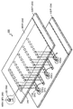
- FIG. 2 is a view showing the internal structure of the LED light emitter using RGB and IR LED according to an embodiment of the present invention.
- an LED light emitter 200 using RGB and IR LEDs may include an LED array 250, a PCB 210, a connector 220, and a cover 230. Include.
- the control unit 130 and the power supply unit 140 described with reference to FIG. 1 are equally applicable to FIG. 2, and are omitted in this drawing to avoid redundant description. 2 is for explaining the structure of the PCB 210 and the connector 220 to make the LED light emitter 200 using the RGB and IR LED to be in close contact with the body parts comfortably.
- the LED light emitter 200 using the RGB and IR LEDs of FIG. 2 is an LED array (eg, R, G, B, IR, RIR, BIR, RG) consisting of R, G, B, IR, or a combination thereof. LED combinations of RGB, RGBIR, Certainly are arranged on the plurality of narrow and long PCBs 210.
- LED array eg, R, G, B, IR, RIR, BIR, RG
- Each of the PCBs 210 is arranged in a row with a plurality of LEDs 250 including two or more of a red LED, a green LED, a blue LED, and an infrared LED.
- the combination of each of the LEDs 250 may vary depending on the embodiment.
- Each of the PCBs 220 may have a width for arranging the LEDs 250 in a line, and each of the PCBs 220 may have an interior (that is, an upper plate portion 232 and a lower plate portion 234) of the cover portion 230. ) May be arranged in parallel (see FIG. 2). That is, by applying a structure in which several LEDs 250 are arranged in a row by narrowing and lengthening the PCBs 220, the LED light emitter 200 may have a structure that can be easily folded.
- the narrow width of the PCBs 210 allows the user of the LED light emitter 200 to comfortably wrap the body part.
- the PCBs 220 may use a flexible substrate to further increase wearability of body parts.
- the LEDs are arranged on the narrow long PCBs 210 (for example, a structure in which 10 LEDs are soldered in series on a PCB having a width of 3 mm and a length of 100 mm), and the narrow long PCBs 210 are connected to the connector. 220 may be connected.
- the connector 220 is disposed on each of the plurality of substrates to electrically connect the plurality of substrates.
- the connection method using the connector 220 may have various methods according to the embodiment.
- two PCBs 210 are illustrated as being connected by the connector 220, but are not necessarily limited thereto.
- all PCBs 210 may be entirely connected by the connector 220.
- three PCBs 210 may be connected by the connector 220.
- Each connector 220 receives power supplied by a controller (not shown) and supplies the power to the LEDs 250 located on the PCBs 210.
- the PCBs 220 connected to the connector 220 are wrapped by a coating 230 such as a soft cloth or a sponge.
- the cladding 230 surrounds the PCBs 210 and the connectors 220, and a plurality of holes are formed to allow light emitted from the LEDs 250 to be emitted to the outside. It consists of a soft material that allows it to be wrapped.
- the coating part 230 may be made of, for example, a cloth, a sponge, a fabric, a leather, or the like.
- the portion where the LEDs 250 are located is configured to open to the outside through the holes formed in the upper plate portion 232. Meanwhile, the LEDs 250 exposed to the outside through the holes may be molded by epoxy in the upper plate 232 (260).
- a controller controls the on / off frequency, driving current, or driving time of the LEDs 250 arranged on the PCBs 210 through the connectors 220.
- the controller may simultaneously control all of the LEDs 250 arranged on the PCBs 210 at the same time, or may independently control the LEDs 250 arranged on the PCBs 210 for each PCB.
- the LEDs may be controlled independently or may be controlled independently of all the LEDs 250 regardless of the PCB position. For example, if the control unit independently controls the LEDs 250 per PCB, the control unit turns on the LEDs located on one PCB and then selects the LEDs located on the adjacent PCB after a predetermined time. It can be turned on.
- a controller may drive each of the RGB and IR LEDs, control the on / off, allow the drive to be driven with an arbitrary on / off frequency, or adjust the driving time.
- the LED current can also be regulated while driving.
- the power supply unit (not shown) supplies DC power to drive the LEDs 250 to the control unit (not shown).
- the power supply (not shown) can be, for example, an adapter, a battery, or a cigar jack for a vehicle.
- the LED light emitter 200 using the RGB and IR LED of Figure 2 is a structure that can comfortably wrap the portion of the wrist, cuffs, knee joints and the like to increase the ease of use.
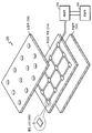
- FIG 3 is a view showing the internal structure of the LED light emitter using RGB and IR LED according to another embodiment of the present invention.
- the LED light emitter 300 using RGB and IR LEDs attaches a flat LED 360 to a flexible PCB 310 and a flat LED ( Holes are formed in the upper plate part 320 of the coating part so that light emitted from the 360 may be emitted to the outside.
- the flexible substrate 310 is arranged such that flat LEDs 360 including two or more of red LEDs, green LEDs, blue LEDs, and infrared LEDs are electrically connected.
- the combination method of the flat LEDs 360 may vary depending on the embodiment. Due to the structural characteristics of the flexible substrate 310 and the geometric characteristics of the flat LEDs 360, it is possible to form a structure that can comfortably wrap body parts such as a wrist, a wrist, a knee joint, and the like.
- the cover parts 320 and 330 may include an upper plate 320 and a lower plate 330 to surround the flexible substrate 310, and the upper plate 320 may emit light emitted from the flat LEDs 360 to the outside. A plurality of holes are formed to make.
- the cover 320, 330 is made of a soft material to wrap the body part.
- the controller 340 may control on / off frequency, driving current, or driving time of the flat LEDs 360 arranged on the flexible substrate 310.
- the power supply unit 350 supplies DC power to drive the flat LEDs 360 to the control unit 340.
- the LED light emitter using RGB and IR LED according to another embodiment of the present invention, there is a method of making the width and length of the PCB the same and make a small shape, and connecting them to the connector (not shown) ).
- the LED light emitter includes a plurality of small substrates, a plurality of connectors, a cover, a controller, and a power supply.
- the plurality of small substrates may each have at least one or more of a red LED, a green LED, a blue LED, and an infrared LED, and may have the same or different widths and lengths. Specifically, at least one or more of the red LED, the green LED, the blue LED, and the infrared LED are arranged and a plurality of small substrates having the same width and length are disposed between the lower plate and the upper plate of the coating unit.
- a connector is disposed on each of the plurality of small substrates to electrically connect the plurality of small substrates. The connectors are disposed on each of the plurality of small substrates to electrically connect the plurality of small substrates.
- a sheath (not shown) surrounds the plurality of small substrates and the plurality of connectors, and a plurality of holes are formed to allow light emitted from the LEDs arranged on the plurality of small substrates to be emitted to the outside. It may be made of a soft material that allows the area to be wrapped.
- a controller (not shown) controls at least one or more of on-off frequency, driving current, and driving time of the LEDs arranged on the plurality of small substrates through the plurality of connectors.
- the power supply unit (not shown) supplies a DC power supply to drive the LEDs arranged on the plurality of small substrates to the control unit.
Landscapes
- Health & Medical Sciences (AREA)
- Engineering & Computer Science (AREA)
- Biomedical Technology (AREA)
- Pathology (AREA)
- Nuclear Medicine, Radiotherapy & Molecular Imaging (AREA)
- Radiology & Medical Imaging (AREA)
- Life Sciences & Earth Sciences (AREA)
- Animal Behavior & Ethology (AREA)
- General Health & Medical Sciences (AREA)
- Public Health (AREA)
- Veterinary Medicine (AREA)
- Led Device Packages (AREA)
- Radiation-Therapy Devices (AREA)
Abstract
La présente invention concerne un émetteur de lumière à LED comprenant : une pluralité de substrats sur lesquels sont alignées plusieurs LED, qui comprennent au moins deux LED parmi une LED rouge (R), une LED verte (G), une LED bleue (B), et une LED infrarouge (IR) ; une pluralité de connecteurs, qui sont disposés sur chaque substrat de la pluralité de substrats, pour connecter électriquement la pluralité de substrats ; une partie de recouvrement, qui recouvre la pluralité de substrats et la pluralité de connecteurs, dotée d'une pluralité de trous pour répandre vers l'extérieur la lumière émise par la pluralité de LED, et qui comprend un matériau mou permettant de couvrir une partie de corps ; une partie formant organe de commande pour commander au moins une fréquence entre fréquence et hors fréquence, un courant d'excitation, et un temps d'excitation de la pluralité de LED qui sont disposées sur la pluralité de substrats, par le biais de la pluralité de connecteurs ; et une partie d'alimentation électrique pour apporter du courant continu à la partie formant organe de commande pour exciter la pluralité de LED, ce qui permet d'aligner la pluralité de substrats, qui sont étroits et longs et sur lesquels les LED sont montées, et de les envelopper avec le matériau mou, de façon à ce que l'émetteur de lumière à LED enveloppe facilement une partie de corps, et offre un confort à la personne qui le porte lorsqu'il répand de la lumière sur une partie de corps (par exemple la région du poignet), ce qui permet d'augmenter la facilité d'utilisation, et d'activer efficacement le métabolisme du corps et de soulager la douleur par l'absorption de lumière ayant diverses longueurs d'onde dans la partie de corps.
Priority Applications (1)
| Application Number | Priority Date | Filing Date | Title |
|---|---|---|---|
| PCT/KR2011/004209 WO2012169673A1 (fr) | 2011-06-08 | 2011-06-08 | Émetteur de lumière à led utilisant des led rouge, verte, bleue et infrarouge |
Applications Claiming Priority (1)
| Application Number | Priority Date | Filing Date | Title |
|---|---|---|---|
| PCT/KR2011/004209 WO2012169673A1 (fr) | 2011-06-08 | 2011-06-08 | Émetteur de lumière à led utilisant des led rouge, verte, bleue et infrarouge |
Publications (1)
| Publication Number | Publication Date |
|---|---|
| WO2012169673A1 true WO2012169673A1 (fr) | 2012-12-13 |
Family
ID=47296218
Family Applications (1)
| Application Number | Title | Priority Date | Filing Date |
|---|---|---|---|
| PCT/KR2011/004209 Ceased WO2012169673A1 (fr) | 2011-06-08 | 2011-06-08 | Émetteur de lumière à led utilisant des led rouge, verte, bleue et infrarouge |
Country Status (1)
| Country | Link |
|---|---|
| WO (1) | WO2012169673A1 (fr) |
Cited By (2)
| Publication number | Priority date | Publication date | Assignee | Title |
|---|---|---|---|---|
| CN103363361A (zh) * | 2013-08-06 | 2013-10-23 | 敦南科技(无锡)有限公司 | 光源发光模组 |
| CN104174119A (zh) * | 2014-09-19 | 2014-12-03 | 重庆海睿科技有限公司 | 一种多光谱理疗智能控制方法及装置 |
Citations (7)
| Publication number | Priority date | Publication date | Assignee | Title |
|---|---|---|---|---|
| US5800478A (en) * | 1996-03-07 | 1998-09-01 | Light Sciences Limited Partnership | Flexible microcircuits for internal light therapy |
| US20020029071A1 (en) * | 2000-03-23 | 2002-03-07 | Colin Whitehurst | Therapeutic light source and method |
| KR20020037348A (ko) * | 1999-08-24 | 2002-05-18 | 토마스 에이. 러셀 | 광선 요법용 가요성 조사 장치 |
| US6743249B1 (en) * | 1997-08-25 | 2004-06-01 | Philip G. Alden | Treatment device for photodynamic therapy and method for making same |
| US20040166146A1 (en) * | 2002-06-12 | 2004-08-26 | University Of Florida | Phototherapy bandage |
| KR100839022B1 (ko) * | 2007-12-10 | 2008-06-17 | 주식회사 루트로닉 | 다파장 출력 의료용 led 광치료기기 |
| KR20110065045A (ko) * | 2009-12-09 | 2011-06-15 | (주)지엘디테크 | Rgb 및 ir led를 이용한 led 빛 방출기 |
-
2011
- 2011-06-08 WO PCT/KR2011/004209 patent/WO2012169673A1/fr not_active Ceased
Patent Citations (7)
| Publication number | Priority date | Publication date | Assignee | Title |
|---|---|---|---|---|
| US5800478A (en) * | 1996-03-07 | 1998-09-01 | Light Sciences Limited Partnership | Flexible microcircuits for internal light therapy |
| US6743249B1 (en) * | 1997-08-25 | 2004-06-01 | Philip G. Alden | Treatment device for photodynamic therapy and method for making same |
| KR20020037348A (ko) * | 1999-08-24 | 2002-05-18 | 토마스 에이. 러셀 | 광선 요법용 가요성 조사 장치 |
| US20020029071A1 (en) * | 2000-03-23 | 2002-03-07 | Colin Whitehurst | Therapeutic light source and method |
| US20040166146A1 (en) * | 2002-06-12 | 2004-08-26 | University Of Florida | Phototherapy bandage |
| KR100839022B1 (ko) * | 2007-12-10 | 2008-06-17 | 주식회사 루트로닉 | 다파장 출력 의료용 led 광치료기기 |
| KR20110065045A (ko) * | 2009-12-09 | 2011-06-15 | (주)지엘디테크 | Rgb 및 ir led를 이용한 led 빛 방출기 |
Cited By (2)
| Publication number | Priority date | Publication date | Assignee | Title |
|---|---|---|---|---|
| CN103363361A (zh) * | 2013-08-06 | 2013-10-23 | 敦南科技(无锡)有限公司 | 光源发光模组 |
| CN104174119A (zh) * | 2014-09-19 | 2014-12-03 | 重庆海睿科技有限公司 | 一种多光谱理疗智能控制方法及装置 |
Similar Documents
| Publication | Publication Date | Title |
|---|---|---|
| KR101180096B1 (ko) | Rgb 및 ir led를 이용한 led 빛 방출기 | |
| US11452883B1 (en) | Hands-free LED device for the treatment of wrinkles, acne, or hair loss | |
| US20070208397A1 (en) | Device and method of phototherapy for jaundiced infants | |
| US8246666B2 (en) | Phototherapy garment | |
| WO2017200334A1 (fr) | Dispositif de soin de la peau des mains | |
| WO2014021557A1 (fr) | Appareil d'irradiation pour traitement de la cavité nasale | |
| US8080047B2 (en) | Light therapy device | |
| US20100106228A1 (en) | Device and method of phototherapy for jaundiced infants | |
| WO2013147424A1 (fr) | Appareil de stimulation d'énergie méridienne abdominale de type ceinture utilisant une diode électroluminescente | |
| KR101543990B1 (ko) | 근적외선 엘이디를 구비한 찜질기 | |
| WO2018182141A1 (fr) | Appareil d'irradiation de lumière pour vagin | |
| WO2012169673A1 (fr) | Émetteur de lumière à led utilisant des led rouge, verte, bleue et infrarouge | |
| WO2014185558A1 (fr) | Dispositif s'utilisant dans le traitement de l'œdème et de la neuropathie | |
| WO2015053550A1 (fr) | Découpeur d'illuminateur | |
| CN101837167B (zh) | 光学治疗装置 | |
| WO2010128751A2 (fr) | Appareil thérapeutique thermique pliable | |
| WO2018182142A1 (fr) | Appareil de soin de la peau | |
| US20260041599A1 (en) | Sexual stimulation device | |
| KR20110065045A (ko) | Rgb 및 ir led를 이용한 led 빛 방출기 | |
| JP3198715U (ja) | フレキシブルled貼付シート | |
| KR20070106946A (ko) | 접이식 황달치료용 발광다이오드 광조사 장치 및 방법 | |
| TWM483061U (zh) | 手持式光療儀 | |
| WO2016072558A1 (fr) | Ceinture portable d'amincissement utilisant des led et des vibrations | |
| CN214851925U (zh) | 可挠式光能量装置 | |
| WO2014081214A1 (fr) | Dispositif de moxibustion à canaux multiples |
Legal Events
| Date | Code | Title | Description |
|---|---|---|---|
| 121 | Ep: the epo has been informed by wipo that ep was designated in this application |
Ref document number: 11867115 Country of ref document: EP Kind code of ref document: A1 |
|
| NENP | Non-entry into the national phase |
Ref country code: DE |
|
| 32PN | Ep: public notification in the ep bulletin as address of the adressee cannot be established |
Free format text: NOTING OF LOSS OF RIGHTS PURSUANT TO RULE 112(1) EPC (EPO FORM 1205A DATED 25/03/2014) |
|
| 122 | Ep: pct application non-entry in european phase |
Ref document number: 11867115 Country of ref document: EP Kind code of ref document: A1 |