WO2012169745A2 - Procédé et dispositif permettant une mesure de canal dans un système de réseau local (lan) sans fil - Google Patents
Procédé et dispositif permettant une mesure de canal dans un système de réseau local (lan) sans fil Download PDFInfo
- Publication number
- WO2012169745A2 WO2012169745A2 PCT/KR2012/004335 KR2012004335W WO2012169745A2 WO 2012169745 A2 WO2012169745 A2 WO 2012169745A2 KR 2012004335 W KR2012004335 W KR 2012004335W WO 2012169745 A2 WO2012169745 A2 WO 2012169745A2
- Authority
- WO
- WIPO (PCT)
- Prior art keywords
- group
- frame
- long
- mimo
- state information
- Prior art date
- Legal status (The legal status is an assumption and is not a legal conclusion. Google has not performed a legal analysis and makes no representation as to the accuracy of the status listed.)
- Ceased
Links
Images


Classifications
-
- H—ELECTRICITY
- H04—ELECTRIC COMMUNICATION TECHNIQUE
- H04W—WIRELESS COMMUNICATION NETWORKS
- H04W24/00—Supervisory, monitoring or testing arrangements
- H04W24/08—Testing, supervising or monitoring using real traffic
-
- H—ELECTRICITY
- H04—ELECTRIC COMMUNICATION TECHNIQUE
- H04B—TRANSMISSION
- H04B7/00—Radio transmission systems, i.e. using radiation field
- H04B7/02—Diversity systems; Multi-antenna system, i.e. transmission or reception using multiple antennas
- H04B7/04—Diversity systems; Multi-antenna system, i.e. transmission or reception using multiple antennas using two or more spaced independent antennas
- H04B7/0413—MIMO systems
- H04B7/0452—Multi-user MIMO systems
-
- H—ELECTRICITY
- H04—ELECTRIC COMMUNICATION TECHNIQUE
- H04B—TRANSMISSION
- H04B7/00—Radio transmission systems, i.e. using radiation field
- H04B7/02—Diversity systems; Multi-antenna system, i.e. transmission or reception using multiple antennas
- H04B7/04—Diversity systems; Multi-antenna system, i.e. transmission or reception using multiple antennas using two or more spaced independent antennas
- H04B7/06—Diversity systems; Multi-antenna system, i.e. transmission or reception using multiple antennas using two or more spaced independent antennas at the transmitting station
- H04B7/0613—Diversity systems; Multi-antenna system, i.e. transmission or reception using multiple antennas using two or more spaced independent antennas at the transmitting station using simultaneous transmission
- H04B7/0615—Diversity systems; Multi-antenna system, i.e. transmission or reception using multiple antennas using two or more spaced independent antennas at the transmitting station using simultaneous transmission of weighted versions of same signal
- H04B7/0617—Diversity systems; Multi-antenna system, i.e. transmission or reception using multiple antennas using two or more spaced independent antennas at the transmitting station using simultaneous transmission of weighted versions of same signal for beam forming
-
- H—ELECTRICITY
- H04—ELECTRIC COMMUNICATION TECHNIQUE
- H04B—TRANSMISSION
- H04B7/00—Radio transmission systems, i.e. using radiation field
- H04B7/02—Diversity systems; Multi-antenna system, i.e. transmission or reception using multiple antennas
- H04B7/04—Diversity systems; Multi-antenna system, i.e. transmission or reception using multiple antennas using two or more spaced independent antennas
- H04B7/06—Diversity systems; Multi-antenna system, i.e. transmission or reception using multiple antennas using two or more spaced independent antennas at the transmitting station
- H04B7/0613—Diversity systems; Multi-antenna system, i.e. transmission or reception using multiple antennas using two or more spaced independent antennas at the transmitting station using simultaneous transmission
- H04B7/0615—Diversity systems; Multi-antenna system, i.e. transmission or reception using multiple antennas using two or more spaced independent antennas at the transmitting station using simultaneous transmission of weighted versions of same signal
- H04B7/0619—Diversity systems; Multi-antenna system, i.e. transmission or reception using multiple antennas using two or more spaced independent antennas at the transmitting station using simultaneous transmission of weighted versions of same signal using feedback from receiving side
- H04B7/0621—Feedback content
- H04B7/0634—Antenna weights or vector/matrix coefficients
-
- H—ELECTRICITY
- H04—ELECTRIC COMMUNICATION TECHNIQUE
- H04B—TRANSMISSION
- H04B7/00—Radio transmission systems, i.e. using radiation field
- H04B7/02—Diversity systems; Multi-antenna system, i.e. transmission or reception using multiple antennas
- H04B7/04—Diversity systems; Multi-antenna system, i.e. transmission or reception using multiple antennas using two or more spaced independent antennas
- H04B7/06—Diversity systems; Multi-antenna system, i.e. transmission or reception using multiple antennas using two or more spaced independent antennas at the transmitting station
- H04B7/0613—Diversity systems; Multi-antenna system, i.e. transmission or reception using multiple antennas using two or more spaced independent antennas at the transmitting station using simultaneous transmission
- H04B7/0615—Diversity systems; Multi-antenna system, i.e. transmission or reception using multiple antennas using two or more spaced independent antennas at the transmitting station using simultaneous transmission of weighted versions of same signal
- H04B7/0619—Diversity systems; Multi-antenna system, i.e. transmission or reception using multiple antennas using two or more spaced independent antennas at the transmitting station using simultaneous transmission of weighted versions of same signal using feedback from receiving side
- H04B7/0636—Feedback format
- H04B7/0645—Variable feedback
- H04B7/065—Variable contents, e.g. long-term or short-short
Definitions
- the present invention relates to a wireless LAN, and more particularly, to a channel measuring method and apparatus in a wireless LAN system.
- WLANs wireless local area networks
- PDAs personal digital assistants
- PMPs portable multimedia players
- IEEE 802.11n aims to increase the speed and reliability of networks and to extend the operating range of wireless networks. More specifically, IEEE 802.11n supports high throughput (HT) with a data processing speed of up to 540 Mbps or more. It is also based on multiple-input and multiple-output (MIMO) technology, which uses multiple antennas at both the transmitter and receiver to minimize transmission errors and optimize data rates.
- MIMO multiple-input and multiple-output
- next generation wireless LAN system supporting very high throughput is the next version of the IEEE 802.11n wireless LAN system, and the data processing speed of 1Gbps or more at the media access control (MAC) service access point (SAP) It is one of the recently proposed IEEE 802.11 WLAN system to support the.
- VHT very high throughput
- MAC media access control
- SAP media access control
- the next generation WLAN system supports MU (multi user) -MIMO transmission in which a plurality of non-AP stations (STAs) simultaneously access a channel in order to use the wireless channel efficiently.
- the AP may simultaneously transmit frames to one or more STAs that are paired with MIMO.
- An object of the present invention is to provide a channel measuring method and apparatus in a wireless LAN system.
- the present invention proposes a method of grouping a plurality of users using long-term information of each user in grouping a plurality of users in order to perform MU-MIMO transmission.
- a method for measuring a channel by a station (STA) in a WLAN system receives a plurality of sounding frames from an access point and estimates the plurality of sounding frames to perform long-term channel state information (LCSI). Generate a group, feed back the generated long-term channel state information to the AP, and receive a group ID management frame including information on a group identifier determined based on the long-term channel state information. Receiving from the AP.
- LCSI long-term channel state information
- the long-term channel state information may be calculated by the equation E T [ H k * H k ].
- E T represents an average over time T
- H k represents a channel matrix of the k-th user
- H k * represents a conjugate transpose matrix of H k .
- the plurality of sounding frames may include sounding frames transmitted to the station.
- the plurality of sounding frames may include sounding frames transmitted to the station and overhear sounding frames transmitted to a second station different from the station.
- the long-term channel state information may be transmitted through an LCSI report field in a very high throughput (VHT) action frame.
- VHT very high throughput
- a method for managing group identifiers by an access point (AP) in a WLAN system transmits a plurality of sounding frames to a plurality of stations and transmits long-term channel state information (LCSI) generated at each station. Calculates a boundary of a time-averaged multi-user (MU) -multiple-input multiple-output (MIMO) sum capacity based on the received long-term channel state information. And transmitting, to the plurality of stations, a group ID management frame including information about a group ID determined based on the boundary of the calculated time averaged MU-MIMO sum capacity.
- LCSI long-term channel state information
- the long-term channel state information may be calculated by the equation E T [ H k * H k ].
- E T represents an average over time T
- H k represents a channel matrix of the k-th user
- H k * represents a conjugate transpose matrix of H k .
- the boundary of the time averaged MU-MIMO sum capacity is Can be calculated by Where I is the interference matrix, signal to noise ratio (SNR) is the signal-to-noise ratio, and K is the total number of users.
- I is the interference matrix
- SNR signal to noise ratio
- K is the total number of users.
- the long-term channel state information may be transmitted through an LCSI report field in a very high throughput (VHT) action frame.
- VHT very high throughput
- a method for managing group identifiers by an access point (AP) in a WLAN system transmits a beamforming feedback request to a plurality of stations, receives a BF feedback frame that is a response to the BF feedback request from the plurality of stations, Generate long-term channel state information (LCSI) based on the received BF feedback frame, and time-averaged multi user (MU) based on the generated long-term channel state information Compute the boundary of the multiple-input multiple-output (MIMO) sum capacity, and includes information about the group ID determined based on the calculated time averaged boundary of the MU-MIMO sum capacity. And transmitting a group ID management frame to the plurality of stations.
- LCSI long-term channel state information
- MU time-averaged multi user
- the BF feedback request and the BF feedback frame may be periodically transmitted and received.
- WLAN wireless local area network
- FIG. 2 shows a PCLP frame structure of IEEE 802.11n.
- FIG. 3 shows an example of a PCLP frame structure of IEEE 802.11ac.
- FIG. 4 shows an example of a structure of a group ID management frame.
- FIG. 5 is a diagram illustrating a channel sounding method using NDP in IEEE 802.11ac.
- FIG. 7 is a block diagram of a WLAN system in which the proposed channel measuring method is implemented.
- FIG 11 shows another embodiment of the proposed channel measuring method.
- FIG. 13 is a block diagram of a wireless device in which an embodiment of the present invention is implemented.
- CDMA code division multiple access
- FDMA frequency division multiple access
- TDMA time division multiple access
- OFDMA orthogonal frequency division multiple access
- SC-FDMA single carrier frequency division multiple access
- CDMA may be implemented by a radio technology such as universal terrestrial radio access (UTRA) or CDMA2000.
- TDMA may be implemented with wireless technologies such as global system for mobile communications (GSM) / general packet radio service (GPRS) / enhanced data rates for GSM evolution (EDGE).
- GSM global system for mobile communications
- GPRS general packet radio service
- EDGE enhanced data rates for GSM evolution
- OFDMA may be implemented in a wireless technology such as IEEE 802.11 (Wi-Fi), IEEE 802.16 (WiMAX), IEEE 802-20, evolved UTRA (E-UTRA).
- IEEE 802.16m is an evolution of IEEE 802.16e and provides backward compatibility with systems based on IEEE 802.16e.
- UTRA is part of a universal mobile telecommunications system (UMTS).
- 3rd generation partnership project (3GPP) long term evolution (LTE) is part of evolved UMTS (E-UMTS) using evolved-UMTS terrestrial radio access (E-UTRA), which employs OFDMA in downlink and SC in uplink -FDMA is adopted.
- LTE-A evolution of 3GPP LTE.
- WLAN wireless local area network
- a WLAN system includes one or more basic service sets (BSSs).
- the BSS is a set of stations (STAs) that can successfully synchronize and communicate with each other, and is not a concept indicating a specific area.
- Infrastructure BSS is a distribution system (DS) that connects one or more non-AP STAs, an access point that provides distribution services, and multiple APs. It includes.
- the AP manages non-AP STAs of the BSS.
- independent BSS IBSS
- IBSS independent BSS
- IBSS non-AP STAs are managed in a distributed manner.
- all STAs may be mobile STAs, and access to a distributed system is not allowed to form a self-contained network.
- a STA is any functional medium that includes a media access control (MAC) conforming to the IEEE 802.11 standard and a physical layer interface to a wireless medium, and broadly includes both AP and non-AP stations.
- MAC media access control
- a non-AP STA is an STA that is not an AP, and a non-AP STA is a mobile terminal, a wireless device, a wireless transmit / receive unit (WTRU), a user equipment (UE), It may also be called another name, such as a mobile station (MS), mobile subscriber unit, or simply user.
- WTRU wireless transmit / receive unit
- UE user equipment
- MS mobile station
- STA mobile subscriber unit
- An AP is a functional entity that provides access to a distributed system via a wireless medium for an associated STA to a corresponding AP.
- communication between STAs is performed via an AP.
- the AP may be called a central controller, a base station (BS), a NodeB, a base transceiver system (BTS), a site controller, or the like.
- a plurality of infrastructure BSSs including the BSS shown in FIG. 1 may be interconnected through a distributed system.
- a plurality of BSSs connected through a distributed system is called an extended service set (ESS).
- the AP and / or STA included in the ESS may communicate with each other, and in the same ESS, the STA may move from one BSS to another BSS while communicating seamlessly.
- the basic access mechanism of the MAC is a carrier sense multiple access with collision avoidance (CSMA / CA) mechanism.
- the CSMA / CA mechanism is also called the distributed coordination function (DCF) of the IEEE 802.11 MAC. It basically employs a “listen before talk” access mechanism.
- DCF distributed coordination function
- the AP and / or STA senses a radio channel or medium prior to initiating transmission. As a result of sensing, if it is determined that the medium is in an idle state, frame transmission is started through the medium. On the other hand, if the medium is detected as occupied status (occupied status), the AP and / or STA does not start the transmission of its own, but waits by setting a delay period for access to the medium.
- the CSMA / CA mechanism also includes virtual carrier sensing in addition to physical carrier sensing in which the AP and / or STA directly sense the medium.
- Virtual carrier sensing is intended to compensate for problems that may occur in media access, such as a hidden node problem.
- the MAC of the WLAN system uses a network allocation vector (NAV).
- the NAV is a value that indicates to the other AP and / or STA how long the AP and / or STA currently using or authorized to use the medium remain until the medium becomes available. Therefore, the value set to NAV corresponds to a period in which the use of the medium is scheduled by the AP and / or STA transmitting the frame.
- the AP and / or STA may perform a procedure of exchanging a request to send (RTS) frame and a clear to send (CTS) frame to indicate that the AP and / or STA want to access the medium.
- the RTS frame and the CTS frame include information indicating a time interval in which a wireless medium required for transmission and reception of an acknowledgment frame (ACK frame) is transmitted and received when actual data frame transmission and acknowledgment are supported. do.
- the other STA that receives the RTS frame transmitted from the AP and / or the STA to which the frame is to be transmitted or receives the CTS frame transmitted from the STA to which the frame is to be transmitted during the time period indicated by the information included in the RTS / CTS frame Can be set to not access the medium. This may be implemented by setting the NAV during the time interval.
- next generation WLAN systems require higher throughput. This is called very high throughput (VHT), and for this purpose, the next-generation wireless LAN system supports 80 MHz, continuous 160 MHz (contiguous 160 MHz), discontinuous 160 MHz (non-contiguous 160 MHz) bandwidth transmission and / or more bandwidth transmission.
- VHT very high throughput
- the next-generation wireless LAN system supports 80 MHz, continuous 160 MHz (contiguous 160 MHz), discontinuous 160 MHz (non-contiguous 160 MHz) bandwidth transmission and / or more bandwidth transmission.
- MU multi-user
- MIMO multiple input multiple output
- the AP may simultaneously transmit data frames to at least one or more STAs paired with MIMO.
- the AP 10 simultaneously transmits data to an STA group including at least one or more STAs among a plurality of STAs 21, 22, 23, 24, and 30 that are associated with the AP 10.
- data transmitted to each STA may be transmitted through different spatial streams.
- the data frame transmitted by the AP 10 may be referred to as a physical layer convergence procedure (PPDU) protocol data unit (PPDU) generated and transmitted in a physical layer (PHY) of the WLAN system.
- PPDU physical layer convergence procedure
- PPDU protocol data unit
- PHY physical layer
- the transmission target STA group paired with the AP 10 and the MU-MIMO are STA1 21, STA2 22, STA3 23, and STA4 24.
- the STAa 30 is an STA coupled with the AP but not included in the transmission target STA group.
- FIG. 2 shows a PCLP frame structure of IEEE 802.11n.
- the legacy PLCP frame includes a legacy short training field (L-STF), a legacy long training field (L-LTF), a legacy signal (L-SIG), and data.
- L-STF legacy short training field
- L-LTF legacy long training field
- L-SIG legacy signal
- data legacy signal
- L-SFT, L-LTF, L-SIG and data may be transmitted in order.
- L-STF may be used for frame timing acquisition and automatic gain control convergence.
- the L-LTF may be used for channel estimation for demodulating data with the L-SIG.
- the L-SIG may include information for demodulating and decoding data.
- the HT green field PLCP frame includes a HT green field short training field (HT-GF-STF), HT long training field (HT-LTF), HT-SIG (HT signal) and data. Include. HT-GF-STF, HT-LTF, HT-SIG and data may be sequentially transmitted in the HT Green Field PLCP frame.
- the HT-GT-STF can be used for frame timing acquisition and automatic gain control concentration.
- the HT-LTF may be used for channel estimation for demodulating data with the HT-SIG.
- the HT-LTF may include data HT-LTF and extension HT-LTF.
- the HT-SIG may include information for demodulating and decoding data.
- the HT green field PLCP frame may be precoded and transmitted.
- the HT mixed mode PLCP frame may include elements of the legacy PLCP frame of Figure 2- (a) and elements of the HT Green Field PLCP frame of Figure 2- (b). That is, the HT mixed mode PLCP frame includes L-STF, L-LTF, L-SIG, HT-SIG, HT-STF, HT-LTF and data.
- the L-STF, L-LTF and L-SIG may be transmitted first so that legacy nodes can receive the HT mixed mode PLCP frame.
- the HT-SIG including information for demodulating and decoding data is transmitted, and HT-STF, HT-LTF, and data for IEEE 802.11n HT STAs may be sequentially transmitted.
- the L-STF to the HT-SIG may be transmitted by a non-beamforming method so that various STAs including legacy nodes may receive information, and the HT-STF to data may be transmitted through precoding. .
- the STA receiving the information by precoding may consider that the power is changed by precoding through the HT-STF.
- MU-MIMO technology for transmitting data by scheduling several STAs at the same time may be applied.
- MU-MIMO can be introduced in IEEE 802.11ac.
- the AP needs to inform the STAs that data is transmitted through a specific spatial stream, and the STAs must be able to actually receive data through the spatial stream.
- a signal indicating STAs to be received by the MU-MIMO and a signal to be received by the STAs by spatial stream position A signal indicating the number of spatial streams may be included.
- a signal indicating STAs to be received by the MU-MIMO may be referred to as a group ID indicator and a signal indicating the number of spatial streams may be referred to as a spatial stream indicator.
- FIG. 3 shows an example of a PCLP frame structure of IEEE 802.11ac.
- the VHT mixed mode PLCP frame of FIG. 3 may further include VHT-SIG for the HT mixed mode PLCP frame of FIG. 2- (c).
- the VHT-SIG may include a group ID indicator and a spatial stream indicator.
- the group ID indicator may carry information on which STAs should receive the MU-MIMO transmission transmitted from the AP, and each group ID and the STA may be logically connected.
- the AP may inform STAs associated with a specific group ID through the group ID management frame before performing the MU-MIMO transmission.
- FIG. 4 shows an example of a structure of a group ID management frame.
- the group ID management frame may be transmitted by the AP to assign or change a user location corresponding to one or more group IDs.
- the AP may transmit the group ID management frame to the grouped STAs in a unicast manner.
- the group ID management frame includes a group ID management information element.
- 4- (b) shows an example of the structure of the group ID management information element.
- the group ID management information element includes an element ID, a length, and a spatial stream position for each group ID.
- the group ID management frame indicates whether the corresponding STA belongs to each group with respect to the entire group ID and how many times the spatial stream location is in the corresponding group. For example, when the value of the spatial stream position in the group ID management information element received by the STA is 0,1,2,4,0,0,0, ..., 0,0,0, the STA is a group ID. 2, it belongs to group ID 3 and group ID 4.
- the group ID 2 indicates that the position of the spatial stream is first
- the group ID 3 indicates the position of the spatial stream is second
- the group ID 4 indicates the position of the spatial stream is fourth.
- the spatial stream position means that when a STA receives a frame having a corresponding group ID, a signal of a position corresponding to the spatial stream position should be received.
- the STA receives a signal corresponding to the second spatial stream.
- the STA receives a signal corresponding to the fourth spatial stream.
- the STA receives a frame having group ID 4
- the STA does not belong to group ID 1 and ignores the frame.
- a channel sounding procedure for obtaining channel information is required.
- Two methods can be supported as a channel sounding procedure.
- One is through a general PPDU including a data field, and the other is through a null data packet (NDP) that does not include a data field.
- NDP null data packet
- the NDP may be called a sounding frame.
- FIG. 5 is a diagram illustrating a channel sounding method using NDP in IEEE 802.11ac.
- the AP is described as performing channel sounding for three transmission target STAs to transmit data to three transmission target STAs as an example, but is not limited thereto.
- the AP may perform channel sounding for one STA.
- the AP 100 transmits an NDPA frame to the STA1 111, the STA2 112, and the STA3 113.
- the NDPA (NDP announcement) frame is for informing information for identifying an STA to which a feedback frame is to be transmitted in response to an NDP transmitted subsequently.
- the AP 100 transmits the STA information field including information on the sounding target STA in the NDPA frame.
- One STA information field may be included for each sounding target STA.
- the NDPA frame may be called a sounding announcement frame.
- the AP 100 when the AP 100 transmits an NDPA frame to at least one or more sounding target STAs for MU-MIMO channel sounding, the AP 100 broadcasts an NDPA frame.
- the receiver address information included in the NDPA frame may be set as the MAC address of the sounding target STA and transmitted by unicast. .
- Table 1 shows an example of the STA information field format included in the NDPA frame.
- Nc indicates the number of columns of beamforming feedback matrices among feedback information received from the sounding target STA to the AP in response to the NDP.
- the STAs that receive the NDPA frame may check the value of the AID subfield included in the STA information field and may determine whether the STA is a sounding target STA.
- the NDPA frame may include a STA information field including the AID of the STA1 111, a STA information field including the AID of the STA2 112, and a STA information field including the AID of the STA3 113. have.
- step S160 the AP 100 transmits the NDP frame to the sounding target STA following the NDPA frame transmission.
- the NDP frame is beamformed by the AP 310 and transmitted to the sounding target STA through at least one spatial stream. Therefore, sounding target STAs 111, 112, and 113 may estimate a channel based on the VHT-LTF of the NDP.
- Control information included in an NDP frame when transmitting an NDP frame the length indicating a length of a PHY service data unit (PSDU) included in a data field or an length of an aggregate-MAC protocol data unit (A-MPDU) included in the PSDU.
- the information may be set to 0 and the information indicating the number of STAs to be transmitted of the NDP frame may be set to 1.
- FIG. A group ID indicating whether a transmission scheme used for transmission of an NDP frame is MU-MIMO or SU-MIMO and indicating a transmission target STA group may be set to a value indicating SU-MIMO transmission.
- the information indicating the number of spatial streams allocated to the transmission target STA may be set to indicate the number of spatial streams transmitted to the transmission target STA through MU-MIMO or SU-MIMO.
- the channel bandwidth information used for the transmission of the NDP frame may be set to the bandwidth value used for the NDPA frame transmission.
- step S171 STA1 (111) transmits a feedback frame to the AP (100).
- the channel bandwidth information used for the feedback frame transmission may be set to be smaller than or equal to the channel bandwidth used for the NDPA frame transmission.
- the AP 100 transmits a feedback poll frame to the STA2 112 after receiving the feedback frame from the STA1 111.
- the feedback poll frame is a frame for requesting a reception STA to transmit a feedback frame.
- the feedback poll frame is transmitted in a unicast manner to the STA to request the feedpack frame transmission.
- the STA2 112 Upon receiving the feedback poll frame in step S172, the STA2 112 transmits a feedback frame to the AP 100.
- the AP 100 transmits a feedback poll frame to the STA3 113, and in step S173, the STA3 113 transmits a feedback frame to the AP 100 in response to the feedback poll frame.
- the channel bandwidth for transmitting data in the WLAN system may vary.
- channel information for various bandwidths may be fed back.
- Next-generation WLAN systems support 20MHz, 40MHz, 80MHz, continuous 160MHz (contiguous 160Mhz) and discrete 160 (80 + 80) MHz (noncontiguous 160Mhz) bandwidth. Therefore, since the channel information for each bandwidth is fed back, the channel feedback information may increase.
- channel information according to channel estimation performed by the STA is transmitted in a feedback frame transmitted by the STA to the AP.
- the feedback frame includes a channel information field and a channel information control field.
- Tables 2 and 3 show the formats of the channel information control field and the channel information field.
- the AP may perform scheduling by selecting a user who uses orthogonal precoding in MU-MIMO scheduling. For example, scheduling may be performed by a per user unitary rate control (PU2RC) technique.
- PU2RC per user unitary rate control
- Various factors may be considered in user grouping for MU-MIMO transmission.
- Various factors considered in user grouping may include capacity, interference, pathloss, etc. of the STA.
- the various elements should be accurately estimated based on the criteria, and user grouping should be implemented with little overhead while maintaining accuracy in consideration of the various factors.
- user grouping must be able to be implemented protocolically within a given standard.
- the MIMO channel model can be expressed as a function of a correlation matrix.
- Equation 1 represents a channel model expressed as a function of the correlation matrix.
- Equation 1 ⁇ is a path loss on a linear scale, R rx is a receive antenna correlation matrix, R tx is a transmit antenna correlation matrix, and W n is an arbitrary complex Gaussian with a mean of 0 and a variance of 1. It is a matrix.
- the correlation matrix may be greatly influenced by the position of the user.
- the correlation matrix may be greatly influenced by ⁇ BS and ⁇ MS , which are determined by user location.
- Equation 2 shows an equation for calculating the transmit antenna correlation matrix and the receive antenna correlation matrix.
- N tx represents the number of transmit antennas
- N rx represents the number of receive antennas
- the MU-MIMO capacity region can be expressed by Equation 3.
- Equation 3 K denotes the maximum number of users, R k denotes an eighth user covariance matrix, and H k denotes a k-th user channel matrix. H k * represents the conjugate transpose matrix of H k .
- Equation 4 the boundary of the MU-MIMO sum capacity can be expressed as Equation 4 when the same power allocation and the precoding matrix are assumed to be a unitary matrix.
- R k SNR / N t ⁇ I.
- Equation 5 shows the boundary of the time averaged MU-MIMO sum capacity.
- Equation 5 E T represents an average value during time T.
- the present invention provides a method for more efficiently time-averaging the MU-MIMO sum capacity boundary.
- the present invention provides a method for determining the boundary of a new time averaged MU-MIMO sum capacity using Jensens' inequality.
- the boundary of the new time averaged MU-MIMO sum capacity may be expressed as shown in Equation 6.
- Equation 6 information of each user's E T [ H k * H k ] is needed to calculate the boundary of the time averaged MU-MIMO sum capacity. Since this is an average value for the time T of the k-th user, it may be channel state information measured in the long term. This may be referred to as long-term channel state information (LCSI). According to Equation 6, the boundary of the MU-MIMO sum capacity averaged by time can be calculated by obtaining information independently for each user without information about all user combinations. In addition, when the present invention is applied, it is possible to operate with less protocol overhead, and can obtain a relatively high accuracy compared to the overhead.
- LCSI long-term channel state information
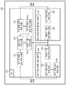
- FIG. 7 is a block diagram of a WLAN system in which the proposed channel measuring method is implemented.
- the AP 210 includes a long-term channel information acquisition module 211, an instantaneous channel information acquisition module 212, a long-term channel information measurement module 213, a performance indicator estimation module 214, and a user group selection module. 215.
- the AP 210 may select long-term channel information from the long-term channel measurable user 220 and estimate a performance indicator based on the long-term channel information to select a user group.
- the AP 210 may acquire instantaneous channel information from the user 230 that cannot measure the long-term channel, estimate the performance index by measuring the long-term channel information, and select a user group.
- the long term channel measurable user 220 includes an instantaneous channel information measurement module 221, a long term channel information measurement module 222, and a user group information acquisition module 223.
- the long-term channel measurable user 220 measures the instantaneous channel information and the long-term channel information, feeds it back to the AP 210, and obtains user group information from the AP 210.
- the long term channel non-measurable user 230 includes an instantaneous channel information measurement module 231 and a user group information acquisition module 232.
- the long-term channel measurement impossible user 230 measures the instantaneous channel information, feeds it back to the AP 210, and obtains user group information from the AP 210.
- the AP transmits the sounding frame to the first STA (STA1) (S300), and transmits the sounding frame to the second STA (STA2) (S301).
- STA1 estimates the sounding frame for a long time to generate E T [ H * H ] (S310), and STA2 similarly estimates the sounding frame for a long time to generate E T [ H * H ] (S311). .
- STA1 and STA2 feed back the generated E T [ H * H ] to the AP (S320, S321).
- the AP calculates a time averaged MU-MIMO sum capacity boundary based on the received E T [ H * H ] (S330).
- the AP transmits information on the user grouping determined based on the calculated time averaged MU-MIMO sum capacity boundary to the STA1 and the STA2 through the group ID management frame (S340 and S341).
- each user may overhear sounding frames transmitted to other users in addition to the sounding frames transmitted to them and use them for channel estimation. Accordingly, the channel can be estimated more quickly and fed back to the AP.
- the AP transmits a sounding frame to STA1 (S400), and transmits a sounding frame to STA2 (S401).
- STA1 estimates the sounding frame transmitted to itself and the overhear sounding frame transmitted to STA2 for a long time to generate E T [ H * H ] (S410), and likewise, STA2 also transmits the sounding frame transmitted to itself and The overhear sounding frame transmitted to STA1 is estimated for a long time to generate E T [ H * H ] (S411).
- STA1 and STA2 feed back the generated E T [ H * H ] to the AP (S420, S421).
- the AP calculates a time averaged MU-MIMO sum capacity boundary based on the received E T [ H * H ] (S430).
- the AP transmits information on the user grouping determined based on the calculated time averaged MU-MIMO sum capacity boundary to the STA1 and the STA2 through the group ID management frame (S440 and S441).
- E T [ H * H ] is a hermitian matrix
- the upper triangle matrix needs to be transmitted.
- the diagonal portion of the upper triangular matrix is a real number, assuming that N b bits are used to represent one value, a total of N b ⁇ N t bits are required.
- the complex part contains a total of N t ⁇ (N t -1) / 2 elements, a total of N b ⁇ N t ⁇ (N t -1) bits is required.
- the LCSI report field may be defined and transmitted through the VHT action frame.
- the AP transmits a BF feedback request to STA1 (S500), and transmits a beamforming (BF) feedback request to STA2 (S501).
- STA1 transmits a BF feedback frame to the AP in response to the BF feedback request (S510), and likewise, STA2 transmits a BF feedback frame to the AP in response to the BF feedback request (S511).
- the BF feedback frame may be referred to as instant channel information.
- AP and STA periodically exchange BF feedback request and BF feedback response.
- the AP generates an E T [ H * H ] based on the BF feedback frame received from each STA (S520).
- the AP calculates a time averaged MU-MIMO sum capacity boundary based on E T [ H * H ] (S530).
- the AP transmits the information on the user grouping determined based on the calculated time averaged MU-MIMO sum capacity boundary to the STA1 and the STA2 through the group ID management frame (S540 and S541).
- the AP may obtain E T [ H * H ] through an uplink (UL) sounding frame assuming channel symmetry.
- FIG 11 shows another embodiment of the proposed channel measuring method.
- the STA1 transmits a UL sounding frame to the AP (S600), and the AP estimates the received UL sounding frame for a long time to generate E T [ H * H ] (S610).
- the AP calculates a time averaged MU-MIMO sum capacity boundary based on the received E T [ H * H ] (S620).
- the AP transmits the information on the user grouping determined based on the calculated time averaged MU-MIMO sum capacity boundary to the STA1 through the group ID management frame (S630).
- the group overload method is a method of managing a combination of 63 or more user groups by assigning multiple user groups to one group ID.
- Group selection method is to select and manage the optimal 63 user groups. As the number of users increases, the group overload method is likely to include most users in all group IDs, which is not suitable for efficiency because the data streams received by most users must be decoded.
- the wireless device may be an AP or a STA.
- the wireless device 900 includes a processor 910, a memory 920, and a transceiver 930 (radio frequency unit).
- Processor 910 implements the proposed functions, processes, and / or methods. Layers of the air interface protocol may be implemented by the processor 910.
- the memory 920 is connected to the processor 910 and stores various information for driving the processor 910.
- the transceiver 930 is connected to the processor 910 to transmit and / or receive a radio signal.
- the processor 910 may include an application-specific integrated circuit (ASIC), another chipset, a logic circuit, and / or a data processing device.
- the memory 920 may include read-only memory (ROM), random access memory (RAM), flash memory, memory card, storage medium, and / or other storage device.
- the transceiver 930 may include a baseband circuit for processing a radio signal.
- the above-described technique may be implemented as a module (process, function, etc.) for performing the above-described function.
- the module may be stored in the memory 920 and executed by the processor 910.
- the memory 920 may be inside or outside the processor 910 and may be connected to the processor 910 by various well-known means.
Landscapes
- Engineering & Computer Science (AREA)
- Computer Networks & Wireless Communication (AREA)
- Signal Processing (AREA)
- Physics & Mathematics (AREA)
- Mathematical Physics (AREA)
- Mobile Radio Communication Systems (AREA)
Abstract
La présente invention se rapporte à un procédé et à un dispositif permettant une mesure de canal dans un système de réseau local (LAN pour Local Area Network) sans fil. Une station (STA) reçoit, d'un point d'accès, (AP pour Access Point) une pluralité de trames sonores, estime la pluralité de trames sonores afin de générer des informations d'état de canal à long terme (LCSI pour Long-term Channel State Information), transmet les informations LCSI générées à l'AP sous la forme d'un signal de rétroaction et reçoit, depuis l'AP, une trame de gestion d'identifiant (ID) de groupe qui comprend des informations concernant un ID de groupe déterminé sur la base des informations LCSI.
Priority Applications (1)
| Application Number | Priority Date | Filing Date | Title |
|---|---|---|---|
| US14/124,584 US9369895B2 (en) | 2011-06-07 | 2012-06-01 | Method and device for channel measurement in a wireless LAN system |
Applications Claiming Priority (2)
| Application Number | Priority Date | Filing Date | Title |
|---|---|---|---|
| US201161494394P | 2011-06-07 | 2011-06-07 | |
| US61/494,394 | 2011-06-07 |
Publications (2)
| Publication Number | Publication Date |
|---|---|
| WO2012169745A2 true WO2012169745A2 (fr) | 2012-12-13 |
| WO2012169745A3 WO2012169745A3 (fr) | 2013-03-07 |
Family
ID=47296563
Family Applications (1)
| Application Number | Title | Priority Date | Filing Date |
|---|---|---|---|
| PCT/KR2012/004335 Ceased WO2012169745A2 (fr) | 2011-06-07 | 2012-06-01 | Procédé et dispositif permettant une mesure de canal dans un système de réseau local (lan) sans fil |
Country Status (2)
| Country | Link |
|---|---|
| US (1) | US9369895B2 (fr) |
| WO (1) | WO2012169745A2 (fr) |
Cited By (2)
| Publication number | Priority date | Publication date | Assignee | Title |
|---|---|---|---|---|
| US9991940B2 (en) | 2013-09-10 | 2018-06-05 | Qualcomm Incorporated | Multi-user multiple-input multiple-output (MU-MIMO) feedback protocol |
| US10616783B2 (en) | 2016-05-10 | 2020-04-07 | Samsung Electronics Co., Ltd | Device grouping based on reported channel information and communication performance |
Families Citing this family (11)
| Publication number | Priority date | Publication date | Assignee | Title |
|---|---|---|---|---|
| US9226302B2 (en) | 2012-08-24 | 2015-12-29 | Huawei Technologies Co., Ltd. | Systems and methods for interference alignment in Wi-Fi |
| US9078153B1 (en) * | 2014-10-31 | 2015-07-07 | Quantenna Communications, Inc. | Wireless local area network with spatial diagnostics |
| US9992789B1 (en) * | 2015-04-21 | 2018-06-05 | Mediatek Inc. | Sounding method and wireless communication system |
| US20170086061A1 (en) * | 2015-09-22 | 2017-03-23 | Qualcomm Incorporated | Dynamic assignment of stations to multi-user group identifiers |
| KR102665974B1 (ko) * | 2016-05-10 | 2024-05-16 | 삼성전자주식회사 | 송신 장치 및 그의 데이터 전송 방법 |
| US10348379B2 (en) * | 2016-07-21 | 2019-07-09 | Symbol Technologies, Llc | Systems, devices and methods for providing communications between a beamforming access point and a non-beamforming device |
| WO2018160223A1 (fr) * | 2017-02-28 | 2018-09-07 | Intel IP Corporation | Appareil, système et procédé de mesure télémétrique multi-utilisateur |
| US20190281608A1 (en) * | 2018-03-09 | 2019-09-12 | Qualcomm Incorporated | Multiple access point channel planning |
| WO2019212152A1 (fr) * | 2018-05-02 | 2019-11-07 | 엘지전자 주식회사 | Procédé de transmission et de réception de signal dans un système lan sans fil, et appareil associé |
| US11552828B2 (en) | 2018-05-04 | 2023-01-10 | Semiconductor Components Industries, Llc | Beamformer solicited sounding |
| TWI801575B (zh) | 2018-05-04 | 2023-05-11 | 美商安森美半導體連線解決方案有限公司 | 波束成形器請求探測 |
Family Cites Families (6)
| Publication number | Priority date | Publication date | Assignee | Title |
|---|---|---|---|---|
| KR100526542B1 (ko) * | 2003-05-15 | 2005-11-08 | 삼성전자주식회사 | 이동 통신 시스템에서 다중안테나를 사용하는송신다이버시티 방식을 사용하여 데이터를 송수신하는장치 및 방법 |
| US8914015B2 (en) | 2006-03-20 | 2014-12-16 | Qualcomm Incorporated | Grouping of users for MIMO transmission in a wireless communication system |
| KR20090030200A (ko) * | 2007-09-19 | 2009-03-24 | 엘지전자 주식회사 | 위상천이 기반의 프리코딩을 이용한 데이터 송수신 방법 및이를 지원하는 송수신기 |
| EP2263340B1 (fr) | 2008-04-11 | 2015-07-15 | Telefonaktiebolaget L M Ericsson (PUBL) | Communication de données codées par le réseau |
| US8594688B2 (en) * | 2009-12-09 | 2013-11-26 | Qualcomm Incorporated | Method and system for rate prediction in coordinated multi-point transmission |
| EP2567467A2 (fr) * | 2010-05-04 | 2013-03-13 | Celeno Communications Ltd. | Système et procédé de rétroaction se rapportant à l'état de canal dans des systèmes à entrées-sorties multiples multiutilisateurs |
-
2012
- 2012-06-01 WO PCT/KR2012/004335 patent/WO2012169745A2/fr not_active Ceased
- 2012-06-01 US US14/124,584 patent/US9369895B2/en not_active Expired - Fee Related
Cited By (3)
| Publication number | Priority date | Publication date | Assignee | Title |
|---|---|---|---|---|
| US9991940B2 (en) | 2013-09-10 | 2018-06-05 | Qualcomm Incorporated | Multi-user multiple-input multiple-output (MU-MIMO) feedback protocol |
| US10498411B2 (en) | 2013-09-10 | 2019-12-03 | Qualcomm Incorporated | Multi-user multiple-input multiple-output (MU-MIMO) feedback protocol |
| US10616783B2 (en) | 2016-05-10 | 2020-04-07 | Samsung Electronics Co., Ltd | Device grouping based on reported channel information and communication performance |
Also Published As
| Publication number | Publication date |
|---|---|
| US20140098701A1 (en) | 2014-04-10 |
| WO2012169745A3 (fr) | 2013-03-07 |
| US9369895B2 (en) | 2016-06-14 |
Similar Documents
| Publication | Publication Date | Title |
|---|---|---|
| WO2012169745A2 (fr) | Procédé et dispositif permettant une mesure de canal dans un système de réseau local (lan) sans fil | |
| KR102243995B1 (ko) | 무선 통신 시스템에서의 사운딩 방법 및 이를 수행하는 장치 | |
| US9525474B2 (en) | Method for performing channel sounding in wireless LAN system and apparatus for supporting same | |
| US9729367B2 (en) | Method and device for processing uplink signal in WLAN system | |
| CN104467931B (zh) | 无线局域网中的节能方法以及无线设备 | |
| CN104320173B (zh) | 在wlan系统中发送数据帧的方法和装置 | |
| CN102804637B (zh) | 执行链路自适应过程的方法 | |
| CN107210987B (zh) | 在无线通信系统中用于多用户发送和接收的方法及其装置 | |
| US10181887B2 (en) | Method and apparatus for reporting channel state information of multi-channel in wireless local area network system | |
| US11105916B2 (en) | Null data packet (NDP) ranging with unassociated stations | |
| CN103299686B (zh) | 在无线局域网系统中发送管理信息帧的方法和设备 | |
| CN102696182B (zh) | 在无线局域网中基于链路自适应来报告信道信息的方法以及用于该方法的装置 | |
| CN103270788B (zh) | 无线局域网系统中的链路自适应方法和设备 | |
| US10153877B2 (en) | Method and apparatus for transmitting feedback frame in wireless local area network system | |
| WO2010143894A2 (fr) | Procédé et appareil de transmission de trames dans un système de réseau local sans fil (wlan) | |
| EP3547560A1 (fr) | Procédé et appareil pour la transmission multitrame permettant la prise en charge de mu-mimo | |
| US20140301383A1 (en) | Method and apapratus for transmitting a frame in a wireless lan system | |
| US20130235836A1 (en) | Method and apparatus for determining modulation and coding scheme feedback in wireless local area network system | |
| US10972196B1 (en) | Trigger frame for ranging | |
| CN103828265A (zh) | 基于频率选择传输发射和接收帧的方法和装置 | |
| KR20130079550A (ko) | 무선랜 시스템에서 채널 사운딩 방법 및 이를 지원하는 장치 | |
| KR102034530B1 (ko) | 무선 통신 시스템에서 다중 프레임 전송 방법 및 전송기 | |
| KR101661219B1 (ko) | 무선 통신 시스템에서의 전송 프레임 필드 값을 산정하는 방법 및 이를 위한 장치 | |
| US20240015541A1 (en) | Client station to client station sensing |
Legal Events
| Date | Code | Title | Description |
|---|---|---|---|
| 121 | Ep: the epo has been informed by wipo that ep was designated in this application |
Ref document number: 12796492 Country of ref document: EP Kind code of ref document: A2 |
|
| WWE | Wipo information: entry into national phase |
Ref document number: 14124584 Country of ref document: US |
|
| NENP | Non-entry into the national phase |
Ref country code: DE |
|
| 122 | Ep: pct application non-entry in european phase |
Ref document number: 12796492 Country of ref document: EP Kind code of ref document: A2 |