WO2012172605A1 - Climatiseur - Google Patents
Climatiseur Download PDFInfo
- Publication number
- WO2012172605A1 WO2012172605A1 PCT/JP2011/003430 JP2011003430W WO2012172605A1 WO 2012172605 A1 WO2012172605 A1 WO 2012172605A1 JP 2011003430 W JP2011003430 W JP 2011003430W WO 2012172605 A1 WO2012172605 A1 WO 2012172605A1
- Authority
- WO
- WIPO (PCT)
- Prior art keywords
- operation mode
- heat medium
- heat
- cooling
- refrigerant
- Prior art date
- Legal status (The legal status is an assumption and is not a legal conclusion. Google has not performed a legal analysis and makes no representation as to the accuracy of the status listed.)
- Ceased
Links
Images

Classifications
-
- F—MECHANICAL ENGINEERING; LIGHTING; HEATING; WEAPONS; BLASTING
- F25—REFRIGERATION OR COOLING; COMBINED HEATING AND REFRIGERATION SYSTEMS; HEAT PUMP SYSTEMS; MANUFACTURE OR STORAGE OF ICE; LIQUEFACTION SOLIDIFICATION OF GASES
- F25B—REFRIGERATION MACHINES, PLANTS OR SYSTEMS; COMBINED HEATING AND REFRIGERATION SYSTEMS; HEAT PUMP SYSTEMS
- F25B30/00—Heat pumps
- F25B30/02—Heat pumps of the compression type
-
- F—MECHANICAL ENGINEERING; LIGHTING; HEATING; WEAPONS; BLASTING
- F25—REFRIGERATION OR COOLING; COMBINED HEATING AND REFRIGERATION SYSTEMS; HEAT PUMP SYSTEMS; MANUFACTURE OR STORAGE OF ICE; LIQUEFACTION SOLIDIFICATION OF GASES
- F25B—REFRIGERATION MACHINES, PLANTS OR SYSTEMS; COMBINED HEATING AND REFRIGERATION SYSTEMS; HEAT PUMP SYSTEMS
- F25B13/00—Compression machines, plants or systems, with reversible cycle
-
- F—MECHANICAL ENGINEERING; LIGHTING; HEATING; WEAPONS; BLASTING
- F24—HEATING; RANGES; VENTILATING
- F24F—AIR-CONDITIONING; AIR-HUMIDIFICATION; VENTILATION; USE OF AIR CURRENTS FOR SCREENING
- F24F11/00—Control or safety arrangements
- F24F11/70—Control systems characterised by their outputs; Constructional details thereof
-
- F—MECHANICAL ENGINEERING; LIGHTING; HEATING; WEAPONS; BLASTING
- F24—HEATING; RANGES; VENTILATING
- F24F—AIR-CONDITIONING; AIR-HUMIDIFICATION; VENTILATION; USE OF AIR CURRENTS FOR SCREENING
- F24F11/00—Control or safety arrangements
- F24F11/70—Control systems characterised by their outputs; Constructional details thereof
- F24F11/80—Control systems characterised by their outputs; Constructional details thereof for controlling the temperature of the supplied air
- F24F11/83—Control systems characterised by their outputs; Constructional details thereof for controlling the temperature of the supplied air by controlling the supply of heat-exchange fluids to heat-exchangers
- F24F11/84—Control systems characterised by their outputs; Constructional details thereof for controlling the temperature of the supplied air by controlling the supply of heat-exchange fluids to heat-exchangers using valves
-
- F—MECHANICAL ENGINEERING; LIGHTING; HEATING; WEAPONS; BLASTING
- F24—HEATING; RANGES; VENTILATING
- F24F—AIR-CONDITIONING; AIR-HUMIDIFICATION; VENTILATION; USE OF AIR CURRENTS FOR SCREENING
- F24F11/00—Control or safety arrangements
- F24F11/89—Arrangement or mounting of control or safety devices
-
- F—MECHANICAL ENGINEERING; LIGHTING; HEATING; WEAPONS; BLASTING
- F24—HEATING; RANGES; VENTILATING
- F24F—AIR-CONDITIONING; AIR-HUMIDIFICATION; VENTILATION; USE OF AIR CURRENTS FOR SCREENING
- F24F3/00—Air-conditioning systems in which conditioned primary air is supplied from one or more central stations to distributing units in the rooms or spaces where it may receive secondary treatment; Apparatus specially designed for such systems
- F24F3/06—Air-conditioning systems in which conditioned primary air is supplied from one or more central stations to distributing units in the rooms or spaces where it may receive secondary treatment; Apparatus specially designed for such systems characterised by the arrangements for the supply of heat-exchange fluid for the subsequent treatment of primary air in the room units
- F24F3/065—Air-conditioning systems in which conditioned primary air is supplied from one or more central stations to distributing units in the rooms or spaces where it may receive secondary treatment; Apparatus specially designed for such systems characterised by the arrangements for the supply of heat-exchange fluid for the subsequent treatment of primary air in the room units with a plurality of evaporators or condensers
-
- F—MECHANICAL ENGINEERING; LIGHTING; HEATING; WEAPONS; BLASTING
- F24—HEATING; RANGES; VENTILATING
- F24F—AIR-CONDITIONING; AIR-HUMIDIFICATION; VENTILATION; USE OF AIR CURRENTS FOR SCREENING
- F24F11/00—Control or safety arrangements
- F24F11/62—Control or safety arrangements characterised by the type of control or by internal processing, e.g. using fuzzy logic, adaptive control or estimation of values
- F24F11/63—Electronic processing
- F24F11/65—Electronic processing for selecting an operating mode
-
- F—MECHANICAL ENGINEERING; LIGHTING; HEATING; WEAPONS; BLASTING
- F25—REFRIGERATION OR COOLING; COMBINED HEATING AND REFRIGERATION SYSTEMS; HEAT PUMP SYSTEMS; MANUFACTURE OR STORAGE OF ICE; LIQUEFACTION SOLIDIFICATION OF GASES
- F25B—REFRIGERATION MACHINES, PLANTS OR SYSTEMS; COMBINED HEATING AND REFRIGERATION SYSTEMS; HEAT PUMP SYSTEMS
- F25B2313/00—Compression machines, plants or systems with reversible cycle not otherwise provided for
- F25B2313/023—Compression machines, plants or systems with reversible cycle not otherwise provided for using multiple indoor units
- F25B2313/0231—Compression machines, plants or systems with reversible cycle not otherwise provided for using multiple indoor units with simultaneous cooling and heating
-
- F—MECHANICAL ENGINEERING; LIGHTING; HEATING; WEAPONS; BLASTING
- F25—REFRIGERATION OR COOLING; COMBINED HEATING AND REFRIGERATION SYSTEMS; HEAT PUMP SYSTEMS; MANUFACTURE OR STORAGE OF ICE; LIQUEFACTION SOLIDIFICATION OF GASES
- F25B—REFRIGERATION MACHINES, PLANTS OR SYSTEMS; COMBINED HEATING AND REFRIGERATION SYSTEMS; HEAT PUMP SYSTEMS
- F25B2313/00—Compression machines, plants or systems with reversible cycle not otherwise provided for
- F25B2313/023—Compression machines, plants or systems with reversible cycle not otherwise provided for using multiple indoor units
- F25B2313/0233—Compression machines, plants or systems with reversible cycle not otherwise provided for using multiple indoor units in parallel arrangements
- F25B2313/02334—Compression machines, plants or systems with reversible cycle not otherwise provided for using multiple indoor units in parallel arrangements during heating
-
- F—MECHANICAL ENGINEERING; LIGHTING; HEATING; WEAPONS; BLASTING
- F25—REFRIGERATION OR COOLING; COMBINED HEATING AND REFRIGERATION SYSTEMS; HEAT PUMP SYSTEMS; MANUFACTURE OR STORAGE OF ICE; LIQUEFACTION SOLIDIFICATION OF GASES
- F25B—REFRIGERATION MACHINES, PLANTS OR SYSTEMS; COMBINED HEATING AND REFRIGERATION SYSTEMS; HEAT PUMP SYSTEMS
- F25B2313/00—Compression machines, plants or systems with reversible cycle not otherwise provided for
- F25B2313/027—Compression machines, plants or systems with reversible cycle not otherwise provided for characterised by the reversing means
- F25B2313/0272—Compression machines, plants or systems with reversible cycle not otherwise provided for characterised by the reversing means using bridge circuits of one-way valves
-
- F—MECHANICAL ENGINEERING; LIGHTING; HEATING; WEAPONS; BLASTING
- F25—REFRIGERATION OR COOLING; COMBINED HEATING AND REFRIGERATION SYSTEMS; HEAT PUMP SYSTEMS; MANUFACTURE OR STORAGE OF ICE; LIQUEFACTION SOLIDIFICATION OF GASES
- F25B—REFRIGERATION MACHINES, PLANTS OR SYSTEMS; COMBINED HEATING AND REFRIGERATION SYSTEMS; HEAT PUMP SYSTEMS
- F25B2313/00—Compression machines, plants or systems with reversible cycle not otherwise provided for
- F25B2313/027—Compression machines, plants or systems with reversible cycle not otherwise provided for characterised by the reversing means
- F25B2313/02732—Compression machines, plants or systems with reversible cycle not otherwise provided for characterised by the reversing means using two three-way valves
-
- F—MECHANICAL ENGINEERING; LIGHTING; HEATING; WEAPONS; BLASTING
- F25—REFRIGERATION OR COOLING; COMBINED HEATING AND REFRIGERATION SYSTEMS; HEAT PUMP SYSTEMS; MANUFACTURE OR STORAGE OF ICE; LIQUEFACTION SOLIDIFICATION OF GASES
- F25B—REFRIGERATION MACHINES, PLANTS OR SYSTEMS; COMBINED HEATING AND REFRIGERATION SYSTEMS; HEAT PUMP SYSTEMS
- F25B2313/00—Compression machines, plants or systems with reversible cycle not otherwise provided for
- F25B2313/027—Compression machines, plants or systems with reversible cycle not otherwise provided for characterised by the reversing means
- F25B2313/02741—Compression machines, plants or systems with reversible cycle not otherwise provided for characterised by the reversing means using one four-way valve
-
- F—MECHANICAL ENGINEERING; LIGHTING; HEATING; WEAPONS; BLASTING
- F25—REFRIGERATION OR COOLING; COMBINED HEATING AND REFRIGERATION SYSTEMS; HEAT PUMP SYSTEMS; MANUFACTURE OR STORAGE OF ICE; LIQUEFACTION SOLIDIFICATION OF GASES
- F25B—REFRIGERATION MACHINES, PLANTS OR SYSTEMS; COMBINED HEATING AND REFRIGERATION SYSTEMS; HEAT PUMP SYSTEMS
- F25B25/00—Machines, plants or systems, using a combination of modes of operation covered by two or more of the groups F25B1/00 - F25B23/00
- F25B25/005—Machines, plants or systems, using a combination of modes of operation covered by two or more of the groups F25B1/00 - F25B23/00 using primary and secondary systems
-
- F—MECHANICAL ENGINEERING; LIGHTING; HEATING; WEAPONS; BLASTING
- F25—REFRIGERATION OR COOLING; COMBINED HEATING AND REFRIGERATION SYSTEMS; HEAT PUMP SYSTEMS; MANUFACTURE OR STORAGE OF ICE; LIQUEFACTION SOLIDIFICATION OF GASES
- F25B—REFRIGERATION MACHINES, PLANTS OR SYSTEMS; COMBINED HEATING AND REFRIGERATION SYSTEMS; HEAT PUMP SYSTEMS
- F25B2700/00—Sensing or detecting of parameters; Sensors therefor
- F25B2700/21—Temperatures
- F25B2700/2106—Temperatures of fresh outdoor air
Definitions
- the present invention relates to an air conditioner applied to, for example, a building multi air conditioner.
- Some air conditioners include a heat source unit (outdoor unit) arranged outside a building and an indoor unit arranged inside a building, such as a building multi-air conditioner.
- the refrigerant circulating in the refrigerant circuit of such an air conditioner radiates heat (heat absorption) to the air supplied to the heat exchanger of the indoor unit, and heats or cools the air.
- the heated or cooled air is sent into the air-conditioning target space for heating or cooling.
- a heat source side refrigerant used in such an air conditioner for example, an HFC (hydrofluorocarbon) refrigerant is often used.
- HFC hydrofluorocarbon
- the heat-source side refrigerant it has also been proposed to use a natural refrigerant such as carbon dioxide (CO 2).
- An air conditioner has been proposed that includes a plurality of indoor units, and each of the plurality of indoor units is configured to be capable of selecting a heating operation or a cooling operation (for example, see Patent Document 1).
- the technology described in Patent Document 1 includes a cooling mode in which all indoor units perform cooling operation, a heating mode in which all indoor units perform heating operation, and cooling and heating simultaneous heating as a heating and cooling simultaneous operation in which the heating load is larger
- This mode includes a cooling / heating simultaneous cooling main mode as a cooling / heating simultaneous operation in which the mode and the cooling load are larger.
- the technique of patent document 1 switches either a heating only mode and a heating / cooling simultaneous heating main mode, or a cooling only mode and a cooling / heating simultaneous cooling main mode by switching either of several four-way valves. Is switched.
- air conditioners with other configurations represented by chiller systems.
- a heat exchanger such as water or antifreeze liquid is heated or cooled by a heat exchanger arranged in the outdoor unit, which is then air-conditioned It is conveyed to a fan coil unit, a panel heater, or the like, which is an indoor unit arranged in (1), and cooling or heating is executed (for example, see Patent Document 2).
- an air conditioner configured such that a heat exchanger for primary refrigerant and secondary refrigerant is arranged in the vicinity of each indoor unit, and the secondary refrigerant is conveyed to the indoor unit (for example, Patent Document 4). reference).
- an air conditioner configured to connect an outdoor unit and a branch unit having a heat exchanger with two pipes and transport a secondary refrigerant to the indoor unit (for example, (See Patent Document 5).
- JP 2006-78026 A for example, FIGS. 1 and 2
- JP-A-5-280818 for example, pages 4, 5 and FIG. 1
- Japanese Patent Laid-Open No. 2001-289465 for example, pages 5 to 8, FIGS. 1 and 2)
- JP 2003-343936 A for example, page 5 and FIG. 1
- Patent Literature 1 uses a four-way valve to switch between an operation mode between a full heating mode and a cooling / heating simultaneous heating main mode, or an operation between a full cooling mode and a cooling / heating simultaneous cooling main mode.
- the mode is switched. Accordingly, when the load required by the indoor unit is frequently changed during the heating operation of the air conditioner, switching between the full heating mode and the simultaneous heating / cooling main heating mode is frequently performed. Even when the air conditioner is in the cooling operation, if the load required by the indoor unit changes frequently, switching between the all-cooling mode and the simultaneous cooling / heating mode is frequently performed.
- the switching of the four-way valve corresponding to the operation mode is accordingly performed. Since the frequency increases, the four-way valve may be worn out and deteriorated. In addition, since the number of switching of the four-way valve is large, the refrigerant pressure fluctuation time generated when the four-way valve is switched has also become longer. In addition, the frequency of switching sound has increased due to the large number of switching of the four-way valve. If the four-way valve having a high switching frequency is installed, for example, in the vicinity of the room, the switching sound is likely to leak into the room, which may reduce the user's comfort.
- Patent Documents 2 and 3 heat or cool a heat medium in a heat source device outside a building and convey it to the indoor unit side. That is, since the heat source unit and the indoor unit are connected by the heat medium pipe, the circulation path becomes longer accordingly.
- the heat medium consumes a large amount of energy due to conveyance power or the like when conveying heat for predetermined heating or cooling work. Therefore, in the techniques described in Patent Documents 2 and 3, the conveyance power is very large due to the long circulation path of the heat medium.
- Patent Document 3 has a plurality of indoor units, and in order to be able to select cooling or heating for each of these indoor units, four pipes are connected from the outdoor side to the indoor side. Is.
- the branch unit and the extension pipe are connected by a total of four pipes including two cooling units and two heating units, as a result, the outdoor unit and the branch unit have four units. It has a configuration similar to that of a system connected by a book pipe. As described above, in the techniques described in Patent Documents 3 and 5, four pipes have to be connected from the outdoor side to the indoor side, resulting in poor workability.
- the present invention has been made to solve at least one of the above-described problems.
- the first object is to provide an air conditioner that is improved in operational reliability by reducing the number of times.
- the number of switching of the four-way valve that switches the operation mode between the all-heating operation mode and the simultaneous heating / cooling main operation mode or the operation mode between the all-cooling operation mode and the simultaneous heating / cooling simultaneous cooling-main operation mode is reduced, and the four-way valve is in the vicinity of the room
- the second object is to provide an air conditioner that prevents the user's comfort from being reduced even if installed.
- An air conditioner includes an outdoor unit on which a compressor, a first refrigerant flow switching device, and a heat source side heat exchanger are mounted, a plurality of heat exchangers between heat media, a plurality of expansion devices, and a plurality of A relay unit on which the second refrigerant flow switching device is mounted and at least one indoor unit on which the use-side heat exchanger is mounted.
- the compressor, the first refrigerant flow switching device, the expansion device, and the second The refrigerant flow switching device and the heat exchanger between heat media are connected by refrigerant pipes to form a refrigeration cycle circuit, and the heat exchanger between heat medium and the use side heat exchanger are connected by heat medium pipes, which are different from the refrigerant.
- Air conditioning that constitutes a heat medium circulation circuit through which the heat medium circulates and switches the second refrigerant flow switching device corresponding to the heat exchanger between heat mediums to function the heat exchanger between heat mediums as a condenser or an evaporator.
- all of the heat exchangers between heat mediums are condensers. From the heating main operation mode, the heating main operation mode having a large heating load, and the heating main operation mode.
- the heating main operation mode When changing to the heating operation mode, when the outside air temperature is equal to or higher than a predetermined temperature, at least one of the heat exchangers functioning as a condenser in the heating main operation mode is continuously operated as a condenser.
- a heating only provisional operation mode in which no refrigerant is supplied to the heat exchanger related to heat medium functioning as an evaporator in the heating main operation mode, and a cooling only operation mode in which all of the heat exchangers related to heat medium function as evaporators , At least one of the heat exchangers between heat mediums functions as an evaporator, and at least one functions as a condenser, and the cooling main operation mode with a large cooling load, and cooling from the cooling main operation mode.
- At least one of the heat exchangers that function as an evaporator in the cooling main operation mode continues to function as an evaporator, It has a cooling only provisional operation mode in which no refrigerant is supplied to the heat exchanger related to heat medium functioning as a condenser in the cooling main operation mode.
- the number of times of switching of the four-way valve (second flow path switching device) corresponding to the operation mode can be reduced.
- the number of refrigerant fluctuations can be reduced, and the operational reliability of the air conditioner can be improved.
- count of switching of a four-way valve can be reduced, the generation frequency of the switching sound correspondingly reduces.
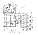
- FIG. 1 It is the schematic which shows the example of installation of the air conditioning apparatus which concerns on embodiment of this invention. It is a figure which shows an example of the refrigerant circuit structure in the air conditioning apparatus which concerns on embodiment of this invention. It is a refrigerant circuit figure which shows the flow of the refrigerant
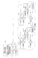
- 3 is a flowchart illustrating control for reducing the number of switching times of a second refrigerant flow switching device in the air conditioning apparatus shown in FIG. 2.
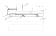
- FIG. 1 is a schematic diagram illustrating an installation example of an air conditioner according to an embodiment of the present invention.
- the air conditioner according to the present embodiment includes an outdoor unit (heat source unit) 1, a plurality of indoor units 3, and one unit interposed between the outdoor unit 1 and the indoor unit 3.
- the relay unit 2 performs heat exchange between the heat source side refrigerant and the heat medium.
- the outdoor unit 1 and the relay unit 2 are connected by a refrigerant pipe 4 through which the heat source side refrigerant flows.
- the relay unit 2 and the indoor unit 3 are connected by a heat medium pipe 5 through which the heat medium flows.
- the cold or warm heat generated by the outdoor unit 1 is delivered to the indoor unit 3 via the relay unit 2.
- the outdoor unit 1 is normally disposed in an outdoor space 6 that is a space outside a building 9 such as a building (for example, a rooftop), and supplies cold or hot heat to the indoor unit 3 via the relay unit 2. .
- the indoor unit 3 is disposed at a position where cooling air or heating air can be supplied to the indoor space 7 that is a space (for example, a living room) inside the building 9, and the cooling air is supplied to the indoor space 7 that is the air-conditioning target space. Alternatively, heating air is supplied.
- the relay unit 2 transmits the heat or cold generated by the outdoor unit 1 to the indoor unit 3.
- the relay unit 2 is configured as a separate housing from the outdoor unit 1 and the indoor unit 3 so as to be installed at a position different from the outdoor space 6 and the indoor space 7.
- the relay unit 2 is connected to the outdoor unit 1 through the refrigerant pipe 4 and is connected to the indoor unit 3 through the heat medium pipe 5.
- the heat source side refrigerant is conveyed from the outdoor unit 1 to the relay unit 2 through the refrigerant pipe 4.
- the conveyed heat source side refrigerant exchanges heat with the heat medium in a heat exchanger between heat mediums (described later) in the relay unit 2 to heat or cool the heat medium. That is, the heat medium is heated or cooled by the heat exchanger between heat mediums to become hot water or cold water.
- the hot water or cold water produced by the relay unit 2 is conveyed to the indoor unit 3 via the heat medium pipe 5 by a heat medium conveying device (described later), and the indoor unit 3 performs heating operation or cooling for the indoor space 7. Used for driving.
- the heat medium for example, water, antifreeze, a mixture of water and antifreeze, or a mixture of water and an additive having a high anticorrosive effect can be used.
- the air conditioning apparatus 100 according to the present embodiment will be described assuming that water is employed as the heat medium.
- the air conditioner according to the present embodiment includes an outdoor unit 1 and a relay unit 2 that use two refrigerant pipes 4, and a relay unit 2 and each indoor unit 3 that have two.
- the heat medium pipes 5 are connected to each other.
- each unit (outdoor unit 1, relay unit 2, and indoor unit 3) is connected using two pipes (refrigerant pipe 4, heat medium pipe 5). Therefore, construction is easy.
- the relay unit 2 is installed in a space such as the back of the ceiling (hereinafter simply referred to as a space 8) that is inside the building 9 but is different from the indoor space 7.
- a space 8 such as the back of the ceiling
- the relay unit 2 can also be installed in a common space where there is an elevator or the like.
- FIG. 1 shows an example in which the indoor unit 3 is a ceiling cassette type, but the present invention is not limited to this, and the indoor unit 3 is not directly limited to the indoor space 7 such as a ceiling embedded type or a ceiling suspended type.
- any type of air can be used as long as heating air or cooling air can be blown out by a duct or the like.
- FIG. 1 shows an example in which the outdoor unit 1 is installed in the outdoor space 6, but the present invention is not limited to this.
- the outdoor unit 1 may be installed in an enclosed space such as a machine room with a ventilation opening. If the waste heat can be exhausted outside the building 9 by an exhaust duct, the outdoor unit 1 may be installed inside the building 9. It may be installed, or may be installed inside the building 9 when the water-cooled outdoor unit 1 is used. Even if the outdoor unit 1 is installed in such a place, no particular problem occurs.
- the relay unit 2 may be installed in the vicinity of the outdoor unit 1. However, when the relay unit 2 is installed in the vicinity of the outdoor unit 1 in this way, it is preferable to pay attention to the length of the heat medium pipe 5 that connects the relay unit 2 to the indoor unit 3. This is because if the distance from the relay unit 2 to the indoor unit 3 is increased, the heat transfer power of the heat medium is increased correspondingly, and the energy saving effect is reduced. Furthermore, the number of connected outdoor units 1, relay units 2, and indoor units 3 is not limited to the number illustrated in FIG. 1, but depends on the building 9 in which the air conditioner according to the present embodiment is installed. And determine the number.
- the plurality of relay units 2 When a plurality of relay units 2 are connected to one outdoor unit, the plurality of relay units 2 can be installed in a common space in a building such as a building or in a space such as a ceiling. By doing so, an air-conditioning load can be covered with the heat exchanger between heat media in each relay unit 2.
- the indoor unit 3 can be installed at a distance or height within the allowable transfer range of the heat medium transfer device in each relay unit 2, and can be arranged on the entire building such as a building. .
- FIG. 2 is a diagram illustrating an example of a refrigerant circuit configuration in the air-conditioning apparatus 100 according to the embodiment of the present invention.
- the outdoor unit 1 and the relay unit 2 are connected by the refrigerant pipe 4 via the heat exchangers 25 a and 25 b provided in the relay unit 2.
- the relay unit 2 and the indoor unit 3 are connected by the heat medium piping 5 via the heat exchangers 25a and 25b.
- the heat exchangers 25 a and 25 b exchange heat between the heat source side refrigerant supplied via the refrigerant pipe 4 and the heat medium supplied via the heat medium pipe 5.
- the refrigerant pipe 4 and the heat medium pipe 5 will be described later.
- the air conditioner 100 includes a refrigerant circulation circuit A that is a refrigeration cycle that circulates a heat source-side refrigerant and a heat medium circulation circuit B that circulates a heat medium.
- the mode in which all the indoor units 3 in operation perform the heating operation is the heating only operation mode
- the mode in which all the indoor units 3 in operation perform the cooling operation are the cooling only operation mode
- the cooling operation and the heating operation is referred to as an air-conditioning mixed operation mode.
- the mixed heating / cooling operation mode includes a cooling main operation mode in which the cooling load is larger and a heating main operation mode in which the heating load is larger.
- the air conditioner 100 has a cooling only provisional operation mode and a heating only provisional operation mode.
- Temporary heating mode is the heat exchange between heat media that functions as a condenser in the heating-main operation mode when the heating-main operation mode is changed to the heating-only operation mode and the outside air temperature is equal to or higher than the predetermined temperature.
- This is an operation mode in which at least one of the units 25 continues to function as a condenser, and refrigerant is not supplied to the heat exchanger related to heat medium functioning as an evaporator in the heating main operation mode.
- the cooling only provisional operation mode refers to the heat medium that functions as an evaporator in the cooling main operation mode when the outside air temperature is equal to or lower than a predetermined temperature when the cooling main operation mode is changed to the cooling only operation mode.
- this operation mode at least one of the heat exchangers 25 is continuously functioned as an evaporator, and the refrigerant is not supplied to the heat exchanger related to heat medium 25 functioning as a condenser in the cooling main operation mode.
- Outdoor unit 1 In the outdoor unit 1, a compressor 10, a first refrigerant flow switching device 11 such as a four-way valve, a heat source side heat exchanger 12, and an accumulator 19 are connected and mounted via a refrigerant pipe 4.
- the outdoor unit 1 is provided with a first connection pipe 4a, a second connection pipe 4b, and check valves 13a to 13d.
- the air conditioner 100 can be connected from the outdoor unit 1 to the relay unit 2 regardless of the heating operation mode or the cooling operation mode.
- the flow of the heat-source-side refrigerant that flows in can be set in a certain direction.
- the compressor 10 sucks in the refrigerant, compresses the refrigerant to a high temperature and high pressure state, and conveys the refrigerant to the refrigerant circuit A.
- the compressor 10 has a discharge side connected to the first refrigerant flow switching device 11 and a suction side connected to an accumulator 19.
- the compressor 10 may be composed of, for example, an inverter compressor capable of capacity control.
- the first refrigerant flow switching device 11 includes a discharge side of the compressor 10, a check valve 13d, a heat source side heat exchanger 12, and an accumulator in the heating only operation mode and the heating main operation mode of the mixed heating and cooling operation mode. 19 suction sides are connected.
- the first refrigerant flow switching device 11 includes a discharge side of the compressor 10, a heat source side heat exchanger 12, and a check valve 13 c in the cooling only operation mode and the cooling main operation mode of the mixed cooling and heating operation mode.
- the suction side of the accumulator 19 is connected.
- the first refrigerant flow switching device 11 may be constituted by a four-way valve, for example.
- the heat source side heat exchanger 12 functions as an evaporator during heating operation, functions as a condenser (or radiator) during cooling operation, and includes a fluid of air supplied from a blower such as a fan (not shown), a heat source side refrigerant, and the like.
- the heat source side refrigerant is evaporated and condensed or liquefied.
- One side of the heat source side heat exchanger 12 is connected to the check valve 13 b and the other side is connected to the suction side of the accumulator 19 in the heating operation mode.
- one of the heat source side heat exchangers 12 is connected to the discharge side of the compressor 10 and the other is connected to the check valve 13a.
- the heat source side heat exchanger 12 may be configured by, for example, a plate fin and tube heat exchanger that can exchange heat between the refrigerant flowing through the refrigerant pipe and the air passing through the fins.
- the accumulator 19 stores surplus refrigerant due to a difference between the heating operation mode and the cooling operation mode, and surplus refrigerant with respect to a transient operation change (for example, a change in the number of operating indoor units 3).
- the accumulator 19 has a suction side connected to the heat source side heat exchanger 12 and a discharge side connected to the suction side of the compressor 10 in the heating operation mode.
- the accumulator 19 has a suction side connected to the check valve 13 c and a discharge side connected to the suction side of the compressor 10 in the cooling operation mode.
- the check valve 13c is provided in the refrigerant pipe 4 between the relay unit 2 and the first refrigerant flow switching device 11, and the heat source side refrigerant is only in a predetermined direction (direction from the relay unit 2 to the outdoor unit 1). It allows flow.
- the check valve 13a is provided in the refrigerant pipe 4 between the heat source side heat exchanger 12 and the relay unit 2, and flows the heat source side refrigerant only in a predetermined direction (direction from the outdoor unit 1 to the relay unit 2). It is acceptable.
- the check valve 13d is provided in the first connection pipe 4a, and causes the heat source side refrigerant discharged from the compressor 10 to flow through the relay unit 2 during the heating operation.
- the check valve 13b is provided in the second connection pipe 4b and circulates the heat source side refrigerant returned from the relay unit 2 during the heating operation to the suction side of the compressor 10.
- the first connection pipe 4 a includes a refrigerant pipe 4 between the first refrigerant flow switching device 11 and the check valve 13 c and a refrigerant pipe 4 between the check valve 13 a and the relay unit 2.
- the second connection pipe 4b includes a refrigerant pipe 4 between the check valve 13c and the relay unit 2, a refrigerant pipe 4 between the heat source side heat exchanger 12 and the check valve 13a, Are connected.
- FIG. 2 shows an example in which the first connection pipe 4a, the second connection pipe 4b, the check valve 13a, the check valve 13b, the check valve 13c, and the check valve 13d are provided.
- the present invention is not limited to this, and these are not necessarily provided.
- the indoor unit 3 includes use side heat exchangers 35a to 35d (also simply referred to as use side heat exchangers 35).
- the use side heat exchanger 35 includes heat medium flow rate adjusting devices 34 a to 34 d (also simply referred to as a heat medium flow rate adjusting device 34) via the heat medium pipe 5 and the second heat heat pipe 35 via the heat medium pipe 5.
- the medium flow switching devices 33a to 33d (also simply referred to as the second heat medium flow switching device 33) are connected.
- the use side heat exchanger 35 exchanges heat between air supplied from a blower such as a fan (not shown) and a heat medium, and generates heating air or cooling air to be supplied to the indoor space 7. To do.
- FIG. 2 shows an example in which four indoor units 3 a to 3 d are connected to the relay unit 2 via the heat medium pipe 5.
- the use side heat exchanger 35 also includes a use side heat exchanger 35a, a use side heat exchanger 35b, a use side heat exchanger 35c, and a use side heat exchanger 35d from the upper side of the drawing. To do.
- the number of indoor units 3 connected is not limited to four.
- the relay unit 2 includes two heat medium heat exchangers 25a and 25b (sometimes simply referred to as the heat medium heat exchanger 25) and two expansion devices 26a and 26b (also simply referred to as the expansion device 26). 2), two opening / closing devices (opening / closing device 27, opening / closing device 29), two second refrigerant flow switching devices 28a, 28b (sometimes simply referred to as second refrigerant flow switching device 28), 2 Two pumps 31a, 31b (sometimes simply referred to as pump 31), four first heat medium flow switching devices 32a to 32d (sometimes simply referred to as first heat medium flow switching device 32), and four Two second heat medium flow switching devices 33a to 33d (sometimes simply referred to as second heat medium flow switching device 33), and four heat medium flow control devices 34a to 34d (simply referred to as heat medium flow control device 34). Sometimes called) , It is mounted.
- the heat exchanger related to heat medium 25 functions as a condenser (heat radiator) or an evaporator, performs heat exchange between the heat source side refrigerant and the heat medium, and generates the cold heat generated in the outdoor unit 1 and stored in the heat source side refrigerant or It transfers heat to the heat medium.
- a condenser radiator
- it functions as a condenser (radiator) to transmit the heat of the heat source side refrigerant to the heat medium
- evaporator the cold heat of the heat source side refrigerant is transmitted to the heat medium.
- the heat exchanger related to heat medium 25a is provided between the expansion device 26a and the second refrigerant flow switching device 28a in the refrigerant circulation circuit A, and serves to cool the heat medium in the air-conditioning mixed operation mode.
- the heat exchanger related to heat medium 25b is provided between the expansion device 26b and the second refrigerant flow switching device 28b in the refrigerant circuit A, and serves to heat the heat medium in the air-conditioning mixed operation mode. It is.
- the expansion device 26 has a function as a pressure reducing valve or an expansion valve, and expands the heat source side refrigerant by reducing the pressure.
- the expansion device 26a is provided on the upstream side of the heat exchanger related to heat medium 25a in the flow of the heat source side refrigerant in the cooling only operation mode.
- the expansion device 26b is provided on the upstream side of the heat exchanger related to heat medium 25b in the flow of the heat source side refrigerant in the cooling only operation mode.
- the expansion device 26 may be configured by a device whose opening degree can be variably controlled, for example, an electronic expansion valve.
- the opening / closing device 27 and the opening / closing device 29 are configured by, for example, electromagnetic valves that can be opened and closed by energization, and open and close a flow path in which they are provided. That is, the opening / closing device 27 and the opening / closing device 29 are controlled to open / close according to the operation mode, and switch the flow path of the heat source side refrigerant.
- the opening / closing device 27 is provided in the refrigerant pipe 4 on the inlet side of the heat-source-side refrigerant (the refrigerant pipe 4 located at the lowest level in the drawing among the refrigerant pipes 4 connecting the outdoor unit 1 and the relay unit 2).
- the opening / closing device 29 is provided in a pipe connecting the refrigerant pipe 4 on the inlet side of the heat source side refrigerant and the refrigerant pipe 4 on the outlet side.
- the opening / closing device 27 and the opening / closing device 29 may be any devices that can open and close the flow path in which they are provided.
- the opening / closing device such as an electronic expansion valve may be controlled.
- the second refrigerant flow switching device 28 is constituted by a four-way valve or the like, and switches the flow of the heat source side refrigerant so that the heat exchanger related to heat medium 25 acts as a condenser or an evaporator according to the operation mode. .
- the second refrigerant flow switching device 28a is provided on the downstream side of the heat exchanger related to heat medium 25a in the flow of the heat source side refrigerant in the cooling only operation mode.
- the second refrigerant flow switching device 28b is provided on the downstream side of the heat exchanger related to heat medium 25b in the flow of the heat source side refrigerant in the cooling only operation mode.
- the pump 31 circulates the heat medium flowing through the heat medium pipe 5 to the heat medium circuit B.
- the pump 31 a is provided in the heat medium pipe 5 between the heat exchanger related to heat medium 25 a and the second heat medium flow switching device 33.
- the pump 31 b is provided in the heat medium pipe 5 between the heat exchanger related to heat medium 25 b and the second heat medium flow switching device 33.
- the pump 31 may be constituted by a capacity-controllable pump, for example, and the flow rate thereof may be adjusted according to the load in the indoor unit 3.
- FIG. 2 an example in which the pump 31 is provided in the heat medium pipe 5 on the downstream side of the heat exchanger 25 between heat mediums is illustrated, but is not limited thereto. That is, the pump 31 may be provided in the heat medium pipe 5 on the upstream side of the heat exchanger related to heat medium 25.
- the first heat medium flow switching device 32 switches the connection between the outlet side of the heat medium flow path of the use side heat exchanger 35 and the inlet side of the heat medium flow path of the heat exchanger related to heat medium 25. .
- the number of first heat medium flow switching devices 32 is set according to the number of indoor units 3 installed (here, four). In the first heat medium flow switching device 32, one of the three sides is in the heat exchanger 25a, one of the three is in the heat exchanger 25b, and one of the three is in the heat medium flow rate. Each is connected to the adjustment device 34 and provided on the outlet side of the heat medium flow path of the use side heat exchanger 35.
- the switching of the heat medium flow path includes not only complete switching from one to the other but also partial switching from one to the other.
- the first heat medium flow switching device 32 may be constituted by a three-way valve, for example.
- the second heat medium flow switching device 33 switches the connection between the outlet side of the heat medium flow path of the inter-heat medium heat exchanger 25 and the inlet side of the heat medium flow path of the use side heat exchanger 35. .
- the second heat medium flow switching device 33 is provided in a number (four in this case) corresponding to the number of indoor units 3 installed.
- one of the three heat transfer medium heat exchangers 25a, one of the three heat transfer medium heat exchangers 25b, and one of the three heat transfer side heats. Each is connected to the exchanger 35 and provided on the inlet side of the heat medium flow path of the use side heat exchanger 35.
- the second heat medium flow switching device 33a, the second heat medium flow switching device 33b, the second heat medium flow switching device 33c, and the second heat medium flow switching are performed from the upper side of the drawing. Illustrated as device 33d.
- the switching of the heat medium flow path includes not only complete switching from one to the other but also partial switching from one to the other.
- the second heat medium flow switching device 33 may be constituted by a three-way valve, for example.
- the heat medium flow control device 34 is configured by a two-way valve or the like that can control the opening area, and controls the flow rate of the heat medium flowing through the heat medium pipe 5.
- the number of the heat medium flow control devices 34 is set according to the number of indoor units 3 installed (four in this case).
- One of the heat medium flow control devices 34 is connected to the use side heat exchanger 35 and the other is connected to the first heat medium flow switching device 32, and is connected to the outlet side of the heat medium flow channel of the use side heat exchanger 35. Is provided.
- the heat medium flow control device 34 adjusts the amount of the heat medium flowing into the indoor unit 3 according to the temperature of the heat medium flowing into the indoor unit 3 and the temperature of the heat medium flowing out, so that the optimum heat according to the indoor load is adjusted.
- the medium amount can be provided to the indoor unit 3.
- the heat medium flow rate adjustment device 34a, the heat medium flow rate adjustment device 34b, the heat medium flow rate adjustment device 34c, and the heat medium flow rate adjustment device 34d are illustrated from the upper side of the drawing.
- the heat medium flow control device 34 may be provided on the inlet side of the heat medium flow path of the use side heat exchanger 35.
- the heat medium flow control device 34 may be provided on the inlet side of the heat medium flow path of the use side heat exchanger 35 and between the second heat medium flow switching device 33 and the use side heat exchanger 35. Good.
- the indoor unit 3 does not require a load such as the stop mode or the thermo OFF, the heat medium supply to the indoor unit 3 can be stopped by fully closing the heat medium flow control device 34.
- the heat medium flow control device 34 may be omitted. Is possible.
- the air conditioner 100 includes an outdoor space temperature detection means 42 that detects the temperature of the outdoor space 6 shown in FIG. 1, and four heat medium temperature detection means that detect the temperature of the heat medium that flows out of the indoor unit 3 and returns to the pump 31. 43a to 43d (simply referred to as heat medium temperature detection means 43) and four heat medium temperature detection means 44a to 44d (simply referred to as heat medium temperature detection) for detecting the temperature of the heat medium sent from the pump 31 to the indoor unit 3. Means 44).
- the outdoor space temperature detection means 42, the heat medium temperature detection means 43, and the heat medium temperature detection means 44 are connected to a control device 51 described later, and these detection results are used for various controls of the air conditioner 100. . These can be composed of, for example, a thermistor.
- the outdoor space temperature detection means 42 detects the temperature of the outdoor space 6.
- the position where the outdoor space temperature detecting means 42 is provided is not particularly limited, but may be provided in the outdoor unit 1 as shown in FIG. 2, for example.
- the heat medium temperature detecting means 43 is provided in the heat medium pipe 5 connecting the use side heat exchanger 35 and the heat medium flow control device 34 and detects the temperature of the heat medium flowing out from the use side heat exchanger 35. It is.
- the number of the heat medium temperature detecting means 43 (four here) according to the number of indoor units 3 installed is provided.
- the position where the heat medium temperature detecting means 43 is installed is not particularly limited, and may be in the indoor unit 3 or in the relay unit 2.
- the heat medium temperature detection means 43d, the heat medium temperature detection means 43c, the heat medium temperature detection means 43b, and the heat medium temperature detection means 43a are illustrated from the lower side of the drawing.
- the heat medium temperature detecting means 44 is provided in the heat medium pipe 5 that connects the second heat medium flow switching device 33 and the use side heat exchanger 35, and detects the temperature of the heat medium flowing into the use side heat exchanger 35. It is to detect.
- the heat medium temperature detecting means 44 is provided in a number (four here) corresponding to the number of indoor units 3 installed.
- the position where the heat medium temperature detecting means 43 is installed is not particularly limited, and may be in the indoor unit 3 or in the relay unit 2.
- the heat medium temperature detection means 44d, the heat medium temperature detection means 44c, the heat medium temperature detection means 44b, and the heat medium temperature detection means 44a are illustrated from the lower side of the drawing.
- the air conditioning apparatus 100 includes four operation modes of normal cooling operation, cooling only operation, cooling main operation, heating only operation, and heating main operation.
- the air conditioning apparatus 100 according to the first embodiment will be described with reference to FIGS. 7 and 8 described later, but as control (four-way valve switching reduction control) for reducing the number of switching times of the second refrigerant flow switching device 28.
- control four-way valve switching reduction control
- a total of six operation modes of a cooling only provisional operation mode and a heating only provisional operation mode are provided. That is, when the air conditioner 100 shifts from the normal operation to the four-way valve switching reduction control operation, the cooling only provisional operation mode and the heating only provisional operation mode can be executed.
- the air conditioning apparatus 100 performs the four-way valve switching reduction control based on the operation mode detection means 41 that detects the operation mode of the air conditioning apparatus 100, the detection results of various detection means, and the like. And a control device 51 for controlling various devices.
- the operation mode detection means 41 detects the operation mode of the air conditioner 100 based on the operation of the indoor units 3a to 3d and the operation load, and outputs the detection result to the control device 51.
- the operation mode detection means 41 determines that the air conditioner 100 is executing the cooling only operation mode when all the indoor units 3a to 3d are in the cooling operation, that is, when the cooling load is 100%.
- the operation mode detection means 41 determines that the cooling main operation mode is being executed when the operation of the indoor units 3a to 3d is a mixture of the cooling operation and the heating operation, but the operation load is larger. To do.
- the operation mode detection means 41 determines that the air conditioner 100 is executing the heating only operation mode when all the indoor units 3a to 3d are in the heating operation, that is, when the heating load is 100%.
- the operation mode detecting means 41 determines that the heating main operation mode is executed when the operation of the indoor units 3a to 3d is a mixture of the cooling operation and the heating operation, but the operation load is larger than the heating load. To do.
- the operation mode detection means 41 only needs to be able to detect the four operation modes, which are normal operations, when executing the four-way valve switching reduction control.
- the control device 51 recognizes the special operation mode when shifting from the heating main operation mode to the heating only operation mode as the heating only provisional operation mode, A special operation mode when shifting from the main operation mode to the cooling only operation mode is recognized as the temporary cooling operation mode.
- the control device 51 is configured by a microcomputer or the like, and the driving frequency of the compressor 10, the rotational speed (including ON / OFF) of the blower (not shown), the first refrigerant flow switching device 11 and the second refrigerant flow switching. Switching of the device 28, opening of the expansion device 26, driving of the pump 31, switching of the switching device 27 and switching device 29, switching of the first heat medium flow switching device 32 and the second heat medium flow switching device 33, heat The opening degree of the medium flow rate adjusting device 34 is controlled. Note that the drive frequency of the compressor 10, the rotational speed of the blower (not shown) (including ON / OFF), and switching of the first refrigerant flow switching device 11 are installed in the outdoor unit 1 and are separate from the control device 51.
- the control device 51 is based on at least detection results of the operation mode detection means 41, the outdoor space temperature detection means 42, the heat medium temperature detection means 43, the heat medium temperature detection means 44, and the like, and an instruction from the remote controller. , To control the various devices described above. Further, the control device 51 has a function of measuring an elapsed time after switching the operation mode.
- the control device 51 switches between the heat medium temperature difference calculating means 45 for calculating the difference between the detection result of the heat medium temperature detecting means 43 and the detection result of the heat medium temperature detecting means 44, and the second refrigerant flow switching device 28.
- the heat medium temperature difference calculating means 45 is configured to detect the temperature of the heat medium flowing out from the use side heat exchanger 35 as a detection result of the heat medium temperature detection means 43 and the use side heat exchange as a detection result of the heat medium temperature detection means 44 The difference with the temperature of the heat medium flowing into the vessel 35 is calculated.
- the four-way valve switching reduction means 50 includes the calculation result of the heat medium temperature difference calculation means 45, the detection result of the operation mode detection means 41, the detection result of the outdoor space temperature detection means 42, and the detection result of the elapsed time after switching the operation mode. Based on the above, calculation is performed so as to reduce the number of times the second refrigerant flow switching device 28 is switched.
- the control device 51 controls the opening degree of the expansion device 26 and the switching of the second refrigerant flow switching device 28 based on the detection result of the four-way valve switching reduction means 50.
- the control device 51 may be provided for each unit of the indoor unit 3 or may be provided in the outdoor unit 1.
- the operation mode executed by the air conditioner 100 includes two modes as control (four-way valve switching reduction control) for reducing the number of times the second refrigerant flow rate switching device 28 is switched to the normal four operation modes.
- control four-way valve switching reduction control
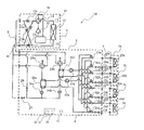
- FIG. 3 is a refrigerant circuit diagram illustrating a refrigerant flow when the air-conditioning apparatus 100 illustrated in FIG. 2 is in the cooling only operation mode.
- the cooling only operation mode will be described by taking as an example a case where a cooling load is generated in all of the use side heat exchangers 35a to 35d.
- the flow direction of the heat source side refrigerant is indicated by solid line arrows, and the flow direction of the heat medium is indicated by broken line arrows.
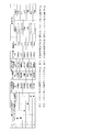
- this cooling only operation mode has a pattern No. shown in FIG. 1 corresponding to the operation mode.
- the outdoor unit 1 switches the first refrigerant flow switching device 11 so that the heat source side refrigerant discharged from the compressor 10 flows into the heat source side heat exchanger 12.
- the pump 31a and the pump 31b are driven, the heat medium flow control devices 34a to 34d are opened, and the heat medium heat exchanger 25a and the heat medium heat exchanger 25b are used respectively.
- the heat medium circulates between the side heat exchanger 35a and the use side heat exchanger 35d.
- the second refrigerant flow switching device 28a and the second refrigerant flow switching device 28b are switched to the cooling side, the opening / closing device 27 is opened, and the opening / closing device 29 is closed.
- the second refrigerant flow switching device 28 is switched to the cooling side means that the refrigerant flowing from the outdoor unit 1 into the relay unit 2 is transferred from the heat exchanger related to heat medium 25 to the second refrigerant. This means that the flow is switched so as to flow in the direction toward the flow path switching device 28.
- the low-temperature and low-pressure refrigerant is compressed by the compressor 10 and discharged as a high-temperature and high-pressure gas refrigerant.
- the high-temperature and high-pressure gas refrigerant discharged from the compressor 10 passes through the first refrigerant flow switching device 11, passes through the heat source side heat exchanger 12, performs heat exchange with the outside air, and performs high-temperature and high-pressure liquid or After becoming a phase refrigerant and passing through the check valve 13 a, it flows through the first connection pipe 4 a and flows out of the outdoor unit 1.
- the high-temperature / high-pressure liquid or two-phase refrigerant that has flowed into the relay unit 2 passes through the opening / closing device 27 and is branched and expanded by the expansion device 26a and the expansion device 26b to become a low-temperature / low-pressure two-phase refrigerant. .
- These two-phase refrigerants evaporate while absorbing heat from the heat medium circulating in the heat medium circuit B, and become low-temperature gas refrigerants.
- the refrigerant is sucked again into the compressor 10 through the two-connection pipe 4b, the first refrigerant flow switching device 11, and the accumulator 19.
- the expansion device 26 calculates a value obtained by converting the pressure of the heat-source-side refrigerant flowing between the heat exchanger 25 between the heat medium 25 and the expansion device 26 into a saturation temperature and the temperature on the outlet side of the heat exchanger 25 between the heat media.
- the opening degree is controlled so that the superheat (superheat degree) obtained as the difference becomes constant.
- the saturation temperature obtained by converting the temperature at the intermediate position may be used instead. In this case, it is not necessary to install a pressure sensor, and the system can be configured at low cost.
- the heat of the heat medium is transmitted to the heat source side refrigerant by both of the heat exchangers 25a and 25b, and the cooled heat medium is pressurized by the pump 31a and the pump 31b.
- the heat medium that has flowed out then flows into the use side heat exchanger 35a to the use side heat exchanger 35d via the second heat medium flow switching device 33a to the second heat medium flow switching device 33d.
- the heat medium absorbs heat from the indoor air in the use side heat exchanger 35a to the use side heat exchanger 35d, thereby cooling the indoor space 7.
- the heat medium flows out from the use side heat exchanger 35a to the use side heat exchanger 35d and flows into the heat medium flow control device 34a to the heat medium flow control device 34d.
- the use side heat exchanger 35a is controlled by the operation of the heat medium flow control device 34a to the heat medium flow control device 34d so that the flow rate of the heat medium is controlled to a flow rate necessary to cover the air conditioning load required in the other room. It flows into the use side heat exchanger 35d.
- the heat medium flowing out from the heat medium flow control device 34a to the heat medium flow control device 34d passes through the first heat medium flow switching device 32a to the first heat medium flow switching device 32d and passes through the heat exchangers 25a and 25a. It flows into the heat exchanger related to heat medium 25b, passes the amount of heat absorbed from the indoor space 7 through the indoor unit 3 to the refrigerant side, and is sucked into the pump 31a and the pump 31b again.
- the heat medium is directed from the second heat medium flow switching device 33 to the first heat medium flow switching device 32 via the heat medium flow control device 34. Is flowing.
- the first heat medium flow switching device 32 and the second heat medium flow switching device 33 seem to secure a flow path that flows to both the heat medium heat exchanger 25a and the heat medium heat exchanger 25b.
- the opening degree is controlled to an intermediate opening degree or an opening degree corresponding to the heat medium temperature at the outlet of the heat exchanger related to heat medium 25a and the heat exchanger related to heat medium 25b.
- the use side heat exchanger 35 is controlled by the temperature difference between the inlet and the outlet.
- the cooling only operation mode shown in FIG. 3 is a mode in which the heat medium circulating in the heat medium circuit B is cooled by the two heat exchangers 25a and 25b (the pattern of FIG. 7 described later). No. 1), even if the expansion device 26b is fully closed and the heat medium circulating in the heat medium circuit B is cooled only by the heat exchanger 25a, the cooling only operation mode can be executed ( This corresponds to pattern No. 2 in FIG.
- These cooling only operation modes are switched according to the load required in the indoor unit 3.
- the cooling only provisional operation mode (pattern No. 2) can be shifted to the cooling only provisional operation mode (pattern NO. 2) only from the cooling main operation mode (pattern NO. 3).
- the cooling only provisional operation mode (pattern No. 2) to the cooling only operation mode (pattern NO. 1) or the cooling main operation mode (pattern NO. 3).
- the switching state of the second refrigerant flow switching devices 28a and 28b is the same as that in the cooling / heating mixed operation. That is, the second refrigerant flow switching device 28a is switched to the cooling side, and the second refrigerant flow switching device 28b is switched to the heating side.
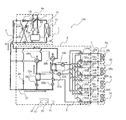
- FIG. 4 is a refrigerant circuit diagram illustrating the refrigerant flow in the cooling main operation mode of the air-conditioning mixed operation mode of the air-conditioning apparatus 100 illustrated in FIG. 2.
- the cooling main operation mode is a pattern NO. 3 is supported.
- FIG. 4 in the mixed operation in which the thermal load is generated in any one of the use side heat exchangers 35 and the cooling load is generated in the rest of the use side heat exchangers 35, The main operation mode will be described.
- the piping represented with the thick line has shown the piping through which the heat source side refrigerant
- the flow direction of the heat source side refrigerant is indicated by solid line arrows, and the flow direction of the heat medium is indicated by broken line arrows.
- This cooling main operation mode is the pattern NO. This corresponds to 3 operation modes.
- the first refrigerant flow switching device 11 uses the heat source side refrigerant discharged from the compressor 10 via the heat source side heat exchanger 12 as a relay unit.
- the pump 31a and the pump 31b are driven to open the heat medium flow rate adjusting device 34a to the heat medium flow rate adjusting device 34d, and the heat exchange between the heat medium heat exchanger 25a and the use side heat exchange in which the heat load is generated.
- the heat medium circulates between the heat exchanger 35 and the heat exchanger 35b between the heat medium and the use side heat exchanger 35 where the heat load is generated.
- the second refrigerant flow switching device 28a is switched to the cooling side, the second refrigerant flow switching device 28b is switched to the heating side, the expansion device 26a is fully opened, the opening / closing device 27 is closed, and the opening / closing device 29 is closed. ing.
- the low-temperature and low-pressure refrigerant is compressed by the compressor 10 and discharged as a high-temperature and high-pressure gas refrigerant.
- the high-temperature and high-pressure gas refrigerant discharged from the compressor 10 passes through the first refrigerant flow switching device 11 and the heat source side heat exchanger 12, passes through the check valve 13a, and flows out of the outdoor unit 1.
- the high-temperature and high-pressure two-phase refrigerant that has flowed out of the outdoor unit 1 flows into the relay unit 2 through the refrigerant pipe 4.
- the high-temperature and high-pressure two-phase refrigerant that has flowed into the relay unit 2 flows through the second refrigerant flow switching device 28b into the heat exchanger related to heat medium 25b that acts as a condenser.
- the two-phase refrigerant flowing into the heat exchanger related to heat medium 25b is condensed and liquefied while dissipating heat to the heat medium circulating in the heat medium circuit B, and becomes a liquid refrigerant.
- the liquid refrigerant flowing out of the heat exchanger related to heat medium 25b is expanded by the expansion device 26b and becomes a low-pressure two-phase refrigerant. This low-pressure two-phase refrigerant flows into the heat exchanger related to heat medium 25a acting as an evaporator via the expansion device 26a.
- the low-pressure two-phase refrigerant that has flowed into the heat exchanger related to heat medium 25a absorbs heat from the heat medium circulating in the heat medium circuit B to become a low-temperature and low-pressure gas refrigerant, and cools the heat medium.
- This low-temperature and low-pressure gas refrigerant flows out of the heat exchanger related to heat medium 25a, flows out of the relay unit 2 through the second refrigerant flow switching device 28a, and flows into the outdoor unit 1 again through the refrigerant pipe 4. To do.
- the low-temperature and low-pressure gas refrigerant that has flowed into the outdoor unit 1 passes through the check valve 13 c and is again sucked into the compressor 10 through the first refrigerant flow switching device 11 and the accumulator 19.
- the opening degree of the expansion device 26b is controlled so that the subcooling (supercooling degree) of the outlet refrigerant of the heat exchanger related to heat medium 25b becomes a target value. Note that the expansion device 26b may be fully opened, and the subcool may be controlled by the expansion device 26a.
- the cooling main operation mode the heat of the heat source side refrigerant is transmitted to the heat medium in the heat exchanger related to heat medium 25b, and the heat medium is caused to flow in the heat medium pipe 5 by the pump 31b.
- the cold heat of the heat source side refrigerant is transmitted to the heat medium in the heat exchanger related to heat medium 25a, and the cooled heat medium is caused to flow in the heat medium pipe 5 by the pump 31a.
- the cooled heat medium that has been pressurized and flowed out by the pump 31a flows into the use-side heat exchanger 35 where the cold load is generated via the second heat medium flow switching device 33, and is pressurized by the pump 31b.
- the heat medium that has flowed out then flows through the second heat medium flow switching device 33 into the use side heat exchanger 35 where the heat load is generated.
- the second heat medium flow switching device 33 is switched to the direction in which the heat exchanger related to heat medium 25b and the pump 31b are connected when the connected indoor unit 3 is in the heating operation mode.
- the indoor unit 3 is switched to the direction in which the heat exchanger related to heat medium 25a and the pump 31a are connected. That is, the second heat medium flow switching device 33 can switch the heat medium supplied to the indoor unit 3 between heating and cooling.
- the cooling operation of the indoor space 7 by the heat medium absorbing heat from the room air or the heating operation of the indoor space 7 by the heat medium radiating heat to the room air is performed.
- the flow rate of the heat medium is controlled to a flow rate necessary to cover the air conditioning load required indoors by the action of the heat medium flow control device 34 and flows into the use side heat exchanger 35. Yes.
- the heat medium that has been used for the cooling operation and has passed through the use-side heat exchanger 35 and has risen in temperature passes through the heat medium flow control device 34 and the first heat medium flow switching device 32, and then the heat exchanger related to heat medium 25a. And is sucked into the pump 31a again.
- the heat medium that has been used for the heating operation and has passed through the use-side heat exchanger 35 and whose temperature has decreased passes through the heat medium flow control device 34 and the first heat medium flow switching device 32, and the heat exchanger related to heat medium 25b. And is sucked into the pump 31b again.
- the first heat medium flow switching device 32 is switched to the direction in which the heat exchanger related to heat medium 25b and the pump 31b are connected when the connected indoor unit 3 is in the heating operation mode,
- the indoor unit 3 is switched to the direction in which the heat exchanger related to heat medium 25a and the pump 31a are connected.
- the warm heat medium and the cold heat medium are not mixed by the action of the first heat medium flow switching device 32 and the second heat medium flow switching device 33, and the use side has a heat load and a heat load, respectively. It is introduced into the heat exchanger 35.
- the heat medium used in the heating operation mode receives heat from the refrigerant as a heating application
- the heat medium used in the cooling operation mode receives heat from the heat medium heat exchanger 25b.
- the heat exchangers 25a, 25a, 25a, 25a, 25c, 25c, 25c, 25c, and 25b are exchanged with the refrigerant, and then are transferred to the pump 31a and the pump 31b.
- the first heat medium flow switching is performed from the second heat medium flow switching device 33 via the heat medium flow control device 34 on both the heating side and the cooling side.
- a heat medium flows in the direction to the device 32.
- the air conditioning load required in the indoor space 7 is the difference in detection results between the heat medium temperature detecting means 43 and the heat medium temperature detecting means 44 corresponding to the heating use side heat exchanger 35 on the heating side.
- On the cooling side so as to keep the difference between the detection results of the heat medium temperature detection means 43 and the heat medium temperature detection means 44 corresponding to the use side heat exchanger 35 for cooling as a target value. Can be covered.
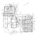
- FIG. 5 is a refrigerant circuit diagram showing a refrigerant flow when the air-conditioning apparatus 100 shown in FIG. 2 is in the heating only operation mode.
- the heating only operation mode will be described by taking as an example a case where a heating load is generated in all of the use side heat exchanger 35a to the use side heat exchanger 35d.
- the pipes represented by the thick lines indicate the pipes through which the heat source side refrigerant flows.
- the flow direction of the heat source side refrigerant is indicated by solid line arrows, and the flow direction of the heat medium is indicated by broken line arrows.
- This heating only operation mode has a pattern No. shown in FIG. 6 operation modes are supported.
- the first refrigerant flow switching device 11 is connected to the relay unit without passing the heat source side refrigerant discharged from the compressor 10 through the heat source side heat exchanger 12.
- Switch to 2 In the relay unit 2, the pump 31a and the pump 31b are driven, the heat medium flow control devices 34a to 34d are opened, and the heat medium heat exchanger 25a and the heat medium heat exchanger 25b are used respectively.
- the heat medium circulates between the side heat exchanger 35a and the use side heat exchanger 35d.
- the second refrigerant flow switching device 28a and the second refrigerant flow switching device 28b are switched to the heating side, the opening / closing device 27 is closed, and the opening / closing device 29 is open.
- the second refrigerant flow switching device 28 is switched to the heating side means that the refrigerant flowing into the relay unit 2 from the outdoor unit 1 is transferred from the second refrigerant flow switching device 28 to the heat medium. It means that it is switched to flow in the direction toward the intermediate heat exchanger 25.
- the low-temperature and low-pressure refrigerant is compressed by the compressor 10 and discharged as a high-temperature and high-pressure gas refrigerant.
- the high-temperature and high-pressure gas refrigerant discharged from the compressor 10 passes through the first refrigerant flow switching device 11, flows through the first connection pipe 4a, passes through the check valve 13d, and flows out of the outdoor unit 1.
- the high-temperature and high-pressure gas refrigerant that has flowed out of the outdoor unit 1 flows into the relay unit 2 through the refrigerant pipe 4.
- the high-temperature and high-pressure gas refrigerant that has flowed into the relay unit 2 is branched and passes through the second refrigerant flow switching device 28a and the second refrigerant flow switching device 28b, and the heat exchanger related to heat medium 25a and the heat between the heat media. It flows into each of the exchangers 25b.
- the high-temperature and high-pressure gas refrigerant flowing into the heat exchanger related to heat medium 25a and the heat exchanger related to heat medium 25b is condensed and liquefied while dissipating heat to the heat medium circulating in the heat medium circuit B, and becomes a high-pressure liquid refrigerant. .
- the liquid refrigerant flowing out of the heat exchanger related to heat medium 25a and the heat exchanger related to heat medium 25b is expanded by the expansion device 26a and the expansion device 26b to become a low-temperature, low-pressure two-phase refrigerant.
- These two-phase refrigerants merge, flow out of the relay unit 2 through the opening / closing device 29, and flow into the outdoor unit 1 again through the refrigerant pipe 4.
- the refrigerant flowing into the outdoor unit 1 flows through the second connection pipe 4b, passes through the check valve 13b, and flows into the heat source side heat exchanger 12 that functions as an evaporator.
- the heat-source-side refrigerant that has flowed into the heat-source-side heat exchanger 12 absorbs heat from the air in the outdoor space 6 (hereinafter referred to as “outside air”) by the heat-source-side heat exchanger 12, and becomes a low-temperature / low-pressure gas refrigerant.
- the low-temperature and low-pressure gas refrigerant flowing out from the heat source side heat exchanger 12 is again sucked into the compressor 10 via the first refrigerant flow switching device 11 and the accumulator 19.
- the expansion device 26 has a value obtained by converting the pressure of the heat-source-side refrigerant flowing between the heat exchanger related to heat medium 25 and the expansion device 26 into a saturation temperature, and the temperature on the outlet side of the heat exchanger related to heat medium 25.
- the degree of opening is controlled so that the subcool (degree of supercooling) obtained as a difference from the above becomes constant.
- the heat of the heat source side refrigerant is transmitted to the heat medium in both the heat exchanger 25a and the heat exchanger 25b, and the heated heat medium is heated by the pump 31a and the pump 31b.
- the inside of the pipe 5 is allowed to flow.
- the heat medium pressurized and discharged by the pump 31a and the pump 31b passes through the second heat medium flow switching device 33a to the second heat medium flow switching device 33d, and the use side heat exchanger 35a to the use side heat exchange.
- the indoor space 7 is heated by the heat medium radiating heat to the indoor air by the use side heat exchanger 35a to the use side heat exchanger 35d.
- the heat medium flows out from the use side heat exchanger 35a to the use side heat exchanger 35d and flows into the heat medium flow control device 34a to the heat medium flow control device 34d.
- the heat medium flow control device 34a to the heat medium flow control device 34d control the flow rate of the heat medium to a flow rate necessary to cover the air conditioning load required indoors, so that the use-side heat exchanger 35a. It flows into the use side heat exchanger 35d.
- the heat medium flowing out from the heat medium flow control device 34a to the heat medium flow control device 34d passes through the first heat medium flow switching device 32a to the first heat medium flow switching device 32d, and then the heat exchanger related to heat medium 25a.
- the heat quantity flowing into the heat exchanger related to heat medium 25b and supplied to the indoor space 7 through the indoor unit 3 is received from the refrigerant side and sucked into the pump 31a and the pump 31b again.
- the heat is transferred in the direction from the second heat medium flow switching device 33 to the first heat medium flow switching device 32 via the heat medium flow control device 34.
- the medium is flowing.
- the air conditioning load required in the indoor space 7 is controlled by keeping the difference between the detection result of the heat medium temperature detection means 43 and the detection result of the heat medium temperature detection means 44 at a target value. I can cover it.
- the first heat medium flow switching device 32 and the second heat medium flow switching device 33 seem to secure a flow path that flows to both the heat medium heat exchanger 25a and the heat medium heat exchanger 25b.
- the opening degree is controlled to an intermediate opening degree or an opening degree corresponding to the heat medium temperature at the outlet of the heat exchanger related to heat medium 25a and the heat exchanger related to heat medium 25b.
- the use side heat exchanger 35 is controlled by the temperature difference between the inlet and the outlet.
- the heating only operation mode When the heating only operation mode is executed, it is not necessary to flow the heat medium to the use side heat exchanger 35 (including the thermo OFF and stop modes) having no heat load, so the flow path is closed by the heat medium flow control device 34. Thus, the heat medium is prevented from flowing to the use side heat exchanger 35.
- the heat medium flows because all of the use side heat exchangers 35a to 35d have a heat load.
- the corresponding heat medium flow control device 34 is used. Can be fully closed. Then, when a heat load is generated again, the corresponding heat medium flow control device 34 is opened, and the heat medium is circulated. The same applies to other operation modes described below.
- the heating only operation mode shown in FIG. 5 is a mode in which the heat medium circulating in the heat medium circuit B is heated by the two heat exchangers 25a and 25b (see FIG. 7 described later).
- the heating device operation mode can be executed even when the expansion device 26a is fully closed and the heat medium circulating in the heat medium circuit B is heated only by the heat exchanger 25b. Yes (corresponding to pattern No. 5 in FIG. 7 described later).
- These heating only operation modes are switched according to the load required in the indoor unit 3.
- the heating only provisional operation mode (pattern No. 5) can be shifted to the heating only provisional operation mode (pattern NO.
- the switching state of the second refrigerant flow switching devices 28a and 28b is the same as that in the cooling / heating mixed operation. That is, the second refrigerant flow switching device 28a is switched to the cooling side, and the second refrigerant flow switching device 28b is switched to the heating side.
- FIG. 6 is a refrigerant circuit diagram illustrating a refrigerant flow in the heating main operation mode of the air-conditioning mixed operation mode of the air-conditioning apparatus 100 illustrated in FIG. 2.
- the heating main operation mode is a pattern NO. 4 is supported.
- FIG. 6 in the mixed operation in which the thermal load is generated in any of the use side heat exchangers 35 and the cold load is generated in the rest of the use side heat exchangers 35, heating is performed.
- the main operation mode will be described.
- the piping represented by the thick line has shown the piping through which the heat source side refrigerant
- the flow direction of the heat source side refrigerant is indicated by solid line arrows, and the flow direction of the heat medium is indicated by broken line arrows.
- the heating main operation mode is a pattern NO. This corresponds to 4 operation modes.
- the first refrigerant flow switching device 11 relays the heat source side refrigerant discharged from the compressor 10 without passing through the heat source side heat exchanger 12. Switch to flow into unit 2.
- the pump 31a and the pump 31b are driven to open the heat medium flow rate adjusting device 34a to the heat medium flow rate adjusting device 34d, and the heat exchange between the heat medium heat exchanger 25a and the use side heat exchange in which the heat load is generated.
- the heat medium circulates between the heat exchanger 35 and the heat exchanger 35b between the heat medium and the use side heat exchanger 35 where the heat load is generated.
- the second refrigerant flow switching device 28a is switched to the cooling side, the second refrigerant flow switching device 28b is switched to the heating side, the expansion device 26a is fully opened, the opening / closing device 27 is closed, and the opening / closing device 29 is closed. ing.
- the low-temperature and low-pressure refrigerant is compressed by the compressor 10 and discharged as a high-temperature and high-pressure gas refrigerant.
- the high-temperature and high-pressure gas refrigerant discharged from the compressor 10 passes through the first refrigerant flow switching device 11 and the check valve 13d and flows out of the outdoor unit 1.
- the high-temperature and high-pressure gas refrigerant that has flowed out of the outdoor unit 1 flows into the relay unit 2 through the refrigerant pipe 4.
- the high-temperature and high-pressure gas refrigerant that has flowed into the relay unit 2 flows into the heat exchanger related to heat medium 25b that acts as a condenser via the second refrigerant flow switching device 28b.
- the high-temperature and high-pressure gas refrigerant that has flowed into the heat exchanger related to heat medium 25b condenses and liquefies while radiating heat to the heat medium circulating in the heat medium circuit B, and becomes liquid refrigerant.
- the liquid refrigerant flowing out of the heat exchanger related to heat medium 25b is expanded by the expansion device 26b and becomes a low-pressure two-phase refrigerant. This low-pressure two-phase refrigerant flows into the heat exchanger related to heat medium 25a acting as an evaporator via the expansion device 26a.
- the low-pressure two-phase refrigerant that has flowed into the heat exchanger related to heat medium 25a evaporates by absorbing heat from the heat medium circulating in the heat medium circuit B, thereby cooling the heat medium.
- the low-pressure two-phase refrigerant flows out of the heat exchanger related to heat medium 25a, flows out of the relay unit 2 through the second refrigerant flow switching device 28a, and flows into the outdoor unit 1 again through the refrigerant pipe 4.
- the low-temperature and low-pressure two-phase refrigerant that has flowed into the outdoor unit 1 passes through the check valve 13b and flows into the heat source side heat exchanger 12 that acts as an evaporator. And the refrigerant
- the low-temperature and low-pressure gas refrigerant flowing out from the heat source side heat exchanger 12 is again sucked into the compressor 10 via the first refrigerant flow switching device 11 and the accumulator 19.
- the opening degree of the expansion device 26b is controlled so that the subcooling (supercooling degree) of the outlet refrigerant of the heat exchanger related to heat medium 25b becomes a target value.
- the heat of the heat source side refrigerant is transmitted to the heat medium in the heat exchanger related to heat medium 25b, and the heated heat medium is caused to flow in the heat medium pipe 5 by the pump 31b.
- the cold heat of the heat source side refrigerant is transmitted to the heat medium by the heat exchanger related to heat medium 25a, and the cooled heat medium is caused to flow in the heat medium pipe 5 by the pump 31a.
- the cooled heat medium that has been pressurized and flowed out by the pump 31a flows into the use-side heat exchanger 35 where the cold load is generated via the second heat medium flow switching device 33, and is pressurized by the pump 31b.
- the heat medium that has flowed out then flows through the second heat medium flow switching device 33 into the use side heat exchanger 35 where the heat load is generated.
- the second heat medium flow switching device 33 is switched to the direction in which the heat exchanger related to heat medium 25b and the pump 31b are connected when the connected indoor unit 3 is in the heating operation mode.
- the indoor unit 3 is switched to the direction in which the heat exchanger related to heat medium 25a and the pump 31a are connected. That is, the second heat medium flow switching device 33 can switch the heat medium supplied to the indoor unit 3 between heating and cooling.
- the cooling operation of the indoor space 7 by the heat medium absorbing heat from the room air or the heating operation of the indoor space 7 by the heat medium radiating heat to the room air is performed.
- the flow rate of the heat medium is controlled to a flow rate necessary to cover the air conditioning load required indoors by the action of the heat medium flow control device 34 and flows into the use side heat exchanger 35. Yes.
- the heat medium that has been used for the cooling operation and has passed through the use-side heat exchanger 35 and has risen in temperature passes through the heat medium flow control device 34 and the first heat medium flow switching device 32, and then the heat exchanger related to heat medium 25a. And is sucked into the pump 31a again.
- the heat medium that has been used for the heating operation and has passed through the use-side heat exchanger 35 and whose temperature has decreased passes through the heat medium flow control device 34 and the first heat medium flow switching device 32, and the heat exchanger related to heat medium 25b. And is sucked into the pump 31b again.
- the first heat medium flow switching device 32 is switched to the direction in which the heat exchanger related to heat medium 25b and the pump 31b are connected when the connected indoor unit 3 is in the heating operation mode,
- the indoor unit 3 is switched to the direction in which the heat exchanger related to heat medium 25a and the pump 31a are connected.
- the warm heat medium and the cold heat medium are not mixed by the action of the first heat medium flow switching device 32 and the second heat medium flow switching device 33, and the use side has a heat load and a heat load, respectively. It is introduced into the heat exchanger 35.
- the heat medium used in the heating operation mode receives heat from the refrigerant as a heating application
- the heat medium used in the cooling operation mode receives heat from the heat medium heat exchanger 25b.
- the heat exchangers 25a, 25a, 25a, 25a, 25c, 25c, 25c, 25c, and 25b are exchanged with the refrigerant, and then are transferred to the pump 31a and the pump 31b.
- the first heat medium flow switching is performed from the second heat medium flow switching device 33 via the heat medium flow control device 34 on both the heating side and the cooling side.
- a heat medium flows in the direction to the device 32.
- the air conditioning load required in the indoor space 7 is the difference in detection results between the heat medium temperature detecting means 43 and the heat medium temperature detecting means 44 corresponding to the heating use side heat exchanger 35 on the heating side.
- On the cooling side so as to keep the difference between the detection results of the heat medium temperature detection means 43 and the heat medium temperature detection means 44 corresponding to the use side heat exchanger 35 for cooling as a target value. Can be covered.
- the air-conditioning apparatus 100 switches the second refrigerant flow switching device 28 to the refrigerant side or the heating side according to the operation mode.
- the control method of the second refrigerant flow switching devices 28a, 28b, the expansion devices 26a, 26b, and the opening / closing device 29 in each mode is as described in the items shown in FIG. Since the switching state of the second refrigerant flow switching device 28 included in the relay unit 2 is determined by the operation state of the indoor unit 3, the operation mode of the plurality of indoor units 3 is frequently switched in the cooling / heating mixed operation mode. When this happens, the switching frequency of the second refrigerant flow switching device 28 of the relay unit 2 also increases as the operation mode of the indoor unit 3 is switched.
- the switching frequency of the second refrigerant flow switching device 28 increases, high durability is required accordingly.
- the switching frequency of the second refrigerant flow switching device 28 increases, the refrigerant pressure fluctuation time generated at the time of switching also becomes longer, so that it is required to suppress the refrigerant pressure fluctuation.
- the switching frequency of the second refrigerant flow switching device 28 is increased, the frequency of occurrence of the switching sound is increased accordingly. Therefore, even if the second refrigerant flow switching device 28 is installed in the vicinity of the room, the user's It is required to suppress a decrease in comfort.
- FIG. 7 is a table explaining the switching of the second refrigerant flow switching device 28 shown in FIG. 2 and the opening degree of the expansion device 26 according to each operation mode.
- SH in FIG. 7 refers to superheat (superheat degree)
- SC refers to subcool (supercool degree).
- the operation mode is switched according to the load requested by the indoor unit 3, and accordingly, the switching of the second refrigerant flow switching device 28 is determined.
- the switching of the second refrigerant flow switching device 28 and the opening degree of the expansion device 26 in each operation mode are as follows.
- the heating only operation mode in which the heat medium circulating in the heat medium circuit B is heated by the two heat medium heat exchangers 25a and 25b is the pattern NO. 6, the two second refrigerant flow switching devices 28 are switched to the heating side, and the opening degrees of the two expansion devices 26 a and 26 b are controlled so that the subcooling is constant. Further, the heating only provisional operation mode in which the heat medium circulating in the heat medium circuit B is heated only by the intermediate heat exchanger 25b is the pattern NO. 5, the second refrigerant flow switching device 28a is switched to the cooling side, and the second refrigerant flow switching device 28b is switched to the heating side.
- the expansion device 26a is fully closed, and the opening of the expansion device 26b is controlled so that the subcool (degree of supercooling) is constant.
- the pattern No. 1 in FIG. 4 the second refrigerant flow switching device 28 a is switched to the cooling side, and the second refrigerant flow switching device 28 b is switched to the heating side.
- the expansion device 26a is fully opened, and the opening degree of the expansion device 26b is controlled so that the subcool (degree of supercooling) is constant. That is, the switching of the second refrigerant flow switching device 28 is the same in the heating main operation mode and the heating only provisional operation mode.
- the pattern No. 4 to pattern NO. In the transition to No. 6, the pattern No. 4 to pattern NO. 6 or pattern NO. 4 to pattern NO. 5 through pattern NO. 6 is assumed to be transferred. Also, the pattern No. 6 to pattern NO. In the transition to No. 4, the pattern No. 6 to pattern NO. 4 and the pattern No. 5 shall not be used.
- the cooling only operation mode for cooling the heat medium circulating in the heat medium circuit B is the pattern NO. 1
- the two second refrigerant flow switching devices 28 are switched to the cooling side, and the apertures of the two expansion devices 26a and 26b are controlled so that the superheat (superheat degree) is constant. Is done.
- the all-cooling provisional operation mode in which the heat medium circulating in the heat medium circuit B is heated only by the heat exchanger between heat mediums 25a is the pattern NO. 2, the second refrigerant flow switching device 28a is switched to the cooling side, and the second refrigerant flow switching device 28b is switched to the heating side.
- the expansion device 26b is fully closed, and the opening degree of the expansion device 26a is controlled so that the superheat is constant.
- the pattern NO. 3 the second refrigerant flow switching device 28 a is switched to the cooling side, and the second refrigerant flow switching device 28 b is switched to the heating side.
- the expansion device 26a is fully opened, and the opening degree of the expansion device 26b is controlled so that the subcool (degree of supercooling) is constant. That is, the switching of the second refrigerant flow switching device 28 is the same in the cooling main operation mode and the all cooling provisional operation mode.
- pattern NO. 1 is assumed to be transferred. Also, the pattern No. 1 to pattern NO. In the transition to No. 3, pattern NO. 1 to pattern NO. 3 and the pattern No. 2 shall not be used. It can be understood from the table of FIG. 7 that the switching of the second refrigerant flow switching device 28 is minimized with respect to the supply capacity of the indoor unit 3.
- FIG. 8 is a flowchart illustrating control (four-way valve switching reduction control) for reducing the number of times of switching of the second refrigerant flow switching device 28 in the air conditioning apparatus 100 shown in FIG. With reference to FIG. 8, the four-way valve switching reduction control executed by the control device 51 will be described.
- Step S201 The control device 51 (four-way valve switching reduction means 50) uses the detection result of the operation mode detection means 41 (information about the operation mode), the detection result of the outdoor space temperature detection means 42, and the calculation result of the heat medium temperature difference calculation means 45. receive. In addition, when the operation mode is switched, the control device 51 also receives information corresponding to the time elapsed since the switching.
- Step S202 The control device 51 (four-way valve switching reduction means 50) determines whether or not the operation mode is the cooling main operation mode (corresponding to the pattern No. 3 in FIG. 7). If it is determined that the cooling main operation mode is selected (YES), the process proceeds to step S204. If it is determined that the mode is not the cooling main operation mode (NO), the process proceeds to step S203.
- Step S203 Control device 51 (four-way valve switching reduction means 50) determines whether or not the operation mode is the heating main operation mode (corresponding to pattern No. 4 in FIG. 7). If it is determined that the mode is the heating-main operation mode (YES), the process proceeds to step S210. Moreover, when it is judged that it is not heating main operation mode (NO), it returns to step S202.
- Step S204 The control device 51 (four-way valve switching reduction means 50) determines whether the detection result Ta of the outdoor space temperature detection means 42 is equal to or lower than a predetermined temperature T1. If it is determined that the detection result Ta is equal to or lower than the predetermined temperature T1 (YES), the process proceeds to step S205. The reason for proceeding to step S205 is that since the outdoor is not so hot, the cooling capability required from the indoor unit 3 can be covered by the all-cooling provisional operation mode. If it is determined that the detection result Ta is not equal to or lower than the predetermined temperature T1 (NO), the process proceeds to step S207. The reason for proceeding to step S207 is that the outdoor is hot, so that the cooling capacity requested from the indoor unit 3 cannot be covered in the cooling main operation mode and the all cooling temporary operation mode.
- the predetermined temperature T1 is preferably 28 ° C., for example.
- Step S205 The control device 51 (four-way valve switching reduction means 50) determines whether or not the operation mode is the all-cooling provisional operation mode (corresponding to the pattern No. 2 in FIG. 7). In this step S205, when the detection result of the operation mode detecting means 41 is the cooling only operation, the control device 51 determines that the cooling is in the temporary cooling temporary operation mode, and the cooling main operation, the heating only operation, and When it is the heating main operation, the control device 51 determines that it is not in the cooling only provisional operation mode. If it is determined that the cooling only temporary operation mode is set (YES), the process proceeds to step S206. If it is determined that the mode is not the all-cooling provisional operation mode (NO), the process proceeds to step S205- (1).
- Step S205- (1) The control device 51 (four-way valve switching reduction means 50) switches the operation mode to the cooling only provisional operation mode. After the control in step S205- (1), the process proceeds to step S205- (2).
- Step S205- (2) The control device 51 (four-way valve switching reduction means 50) determines whether or not a predetermined time has elapsed since switching to the all-cooling provisional operation mode. In addition, as shown in FIG. 8, as predetermined time, it is good to set it as 30 minutes or more, for example. If it is determined that the predetermined time or more has elapsed (YES), the process proceeds to step S206. If it is determined that the predetermined time or more has not elapsed (NO), step S205- (2) is executed again.
- Step S206 The control device 51 (four-way valve switching reduction means 50) determines whether or not the detection result Tb of the heat medium temperature difference calculation means 45 is greater than a predetermined value T10. If it is determined that the detection result Tb is greater than the predetermined value T10 (YES), the process returns to step S204. The reason for returning to step S204 is that the detection result Tb is larger than the predetermined value T10, so that the cooling operation capability in the all cooling temporary operation mode is sufficient. If it is determined that the detection result Tb is not greater than the predetermined value T10 (NO), the process proceeds to step S207.
- the reason for proceeding to step S207 is that the detection result Tb is not greater than the predetermined value T10, and thus the cooling operation capability in the all-cooling provisional operation mode is insufficient.
- the predetermined temperature T10 is preferably set to 5 ° C., for example.
- Step S207 The control device 51 (four-way valve switching reduction means 50) switches the operation mode to the cooling only operation mode.
- Step S210 The control device 51 (four-way valve switching reduction means 50) determines whether the detection result Ta of the outdoor space temperature detection means 42 is equal to or higher than a predetermined temperature T0. If it is determined that the detection result Ta is equal to or higher than the predetermined temperature T0 (YES), the process proceeds to step S211. The reason for proceeding to step S211 is that since the outdoor is not so cold, the heating capacity required from the indoor unit 3 can be covered by the total heating provisional operation mode. If it is determined that the detection result Ta is not equal to or higher than the predetermined temperature T0 (NO), the process proceeds to step S213.
- the reason for proceeding to step S213 is that since the outdoor is cold, the heating capability requested from the indoor unit 3 cannot be covered in the heating main operation mode and the all heating provisional operation mode.
- the predetermined temperature T0 is preferably set to ⁇ 5 ° C., for example.
- Step S211 Control device 51 (four-way valve switching reduction means 50) determines whether or not the operation mode is a heating only provisional operation mode (corresponding to pattern No. 5 in FIG. 7). In this step S211, when the detection result of the operation mode detecting means 41 is the heating only operation, the control device 51 determines that the heating is in the temporary heating operation mode, and the cooling only operation, the cooling main operation, When it is the heating main operation, the control device 51 determines that it is not in the all heating temporary operation mode. When it is determined that the heating only provisional operation mode is set (YES), the process proceeds to step S212. If it is determined that it is not in the all heating provisional operation mode (NO), the process proceeds to step S211-(1).
- Step S211-(1) The control device 51 (four-way valve switching reduction means 50) switches the operation mode to the heating only provisional operation mode. After the control in step S211- (1), the process proceeds to step S205- (2).
- Step S211- (2) The control device 51 (four-way valve switching reduction means 50) determines whether or not a predetermined time has elapsed since switching to the heating only provisional operation mode. In addition, as shown in FIG. 8, as predetermined time, it is good to set it as 30 minutes or more, for example. If it is determined that the predetermined time or more has elapsed (YES), the process proceeds to step S212. If it is determined that the predetermined time or more has not elapsed (NO), step S211-(2) is executed again.
- Step S212 The control device 51 (four-way valve switching reduction means 50) determines whether or not the detection result Tb of the heat medium temperature difference calculation means 45 is greater than a predetermined value T10. If it is determined that the detection result Tb is greater than the predetermined value T10 (YES), the process returns to step S210. The reason for returning to step S210 is that the detection result Tb is larger than the predetermined value T10, so that the heating operation capability in the all heating provisional operation mode is sufficient. If it is determined that the detection result Tb is not greater than the predetermined value T10 (NO), the process proceeds to step S213.
- the reason for proceeding to step S213 is that the detection result Tb is not greater than the predetermined value T10, so that the capacity of the heating operation in the heating only provisional operation mode is insufficient.
- the predetermined temperature T10 is preferably set to 5 ° C., for example.
- Step S213 The control device 51 (four-way valve switching reduction means 50) switches the operation mode to the heating only operation mode.
- the conventional air conditioner capable of executing the mixed heating / cooling operation mode is to switch the flow switching device such as a four-way valve between the cooling main operation mode and the cooling only operation mode and between the heating main operation mode and the heating only operation mode.
- the reduction in the number of times was not considered.
- the air conditioner 100 according to the present embodiment includes the all-cooling provisional operation mode and the all-heating provisional operation mode, and can execute the four-way valve switching reduction control by the four-way valve switching reduction unit 50. it can.
- the air-conditioning apparatus 100 can reduce the number of times of switching of the second refrigerant flow switching device 28, so that deterioration and switching due to the operation of the second refrigerant flow switching device 28 are reduced.
- the number of refrigerant fluctuations can be reduced, and the operational reliability of the air conditioner 100 can be improved.
- coolant flow path switching apparatus 28 can be reduced, the generation frequency of the switching sound can be reduced that much.
- coolant flow path switching device 28 demonstrated as what was comprised with the four-way valve, you may comprise with what has a function equivalent to a four-way valve, combining a three-way valve, a two-way valve, etc., for example.
- the relay unit 2 and the indoor unit 3 are connected via the heat medium pipe 5, and the outdoor unit 1 and the indoor unit 3 are connected to the heat medium pipe. It is not the structure connected by 5. That is, since the outdoor unit 1 and the relay unit 2 are not connected by the heat medium pipe, the entire length of the heat medium pipe 5 can be shortened. Thereby, compared with a heat source side refrigerant
- coolant since the conveyance distance of the heat medium with comparatively low conveyance efficiency can be shortened, energy saving can be achieved.
- the number of pipes connecting the outdoor unit 1 and the relay unit 2 is two.
- the number of pipes connecting the relay unit 2 and the indoor unit 3 is the number of indoor units 3 ⁇ 2.
- the air conditioner 100 does not have a configuration in which the pumps 31a and 31b for conveying the heat medium are individually mounted for each of the indoor units 3a to 3d. That is, since the air conditioning apparatus 100 has two installed pumps, the cost can be increased and the sound generated from the pumps can be suppressed. Furthermore, since the air conditioning apparatus 100 does not have the configuration in which the refrigerant pipe 4 is disposed in the vicinity of the indoor unit 3, the heat source side refrigerant is suppressed from leaking into the indoor space or the vicinity of the indoor space.
Landscapes
- Engineering & Computer Science (AREA)
- Mechanical Engineering (AREA)
- General Engineering & Computer Science (AREA)
- Chemical & Material Sciences (AREA)
- Combustion & Propulsion (AREA)
- Physics & Mathematics (AREA)
- Thermal Sciences (AREA)
- Air Conditioning Control Device (AREA)
Abstract
La présente invention a trait à un climatiseur qui est doté : d'un mode de fonctionnement provisoire de chauffage total permettant, lors du passage d'un mode de fonctionnement de dispositif de chauffage principal à un mode de fonctionnement de chauffage total, si la température extérieure est supérieure ou égale à une température prescrite, à au moins un échangeur de chaleur de support de chaleur intermédiaire (25), qui fonctionne en tant que condensateur dans le mode de fonctionnement de dispositif de chauffage principal, de fonctionner en continu en tant que condensateur, et permettant de ne pas fournir de fluide frigorigène à un échangeur de chaleur de support de chaleur intermédiaire (25) qui fonctionne en tant qu'évaporateur dans le mode de fonctionnement de dispositif de chauffage principal ; et d'un mode de fonctionnement provisoire de refroidissement total permettant, lors du passage d'un mode de fonctionnement de dispositif de refroidissement principal à un mode de fonctionnement de refroidissement total, si la température extérieure est inférieure ou égale à une température prescrite, à au moins un échangeur de chaleur de support de chaleur intermédiaire (25), qui fonctionne en tant qu'évaporateur dans le mode de fonctionnement de dispositif de refroidissement principal, de fonctionner en continu en tant qu'évaporateur, et permettant de ne pas fournir de fluide frigorigène à l'échangeur de chaleur de support de chaleur intermédiaire (25) qui fonctionne en tant que condensateur dans le mode de fonctionnement de dispositif de refroidissement principal.
Priority Applications (5)
| Application Number | Priority Date | Filing Date | Title |
|---|---|---|---|
| PCT/JP2011/003430 WO2012172605A1 (fr) | 2011-06-16 | 2011-06-16 | Climatiseur |
| JP2013520414A JP5677571B2 (ja) | 2011-06-16 | 2012-05-23 | 空気調和装置 |
| EP12800116.1A EP2722608B1 (fr) | 2011-06-16 | 2012-05-23 | Climatiseur |
| PCT/JP2012/003355 WO2012172731A1 (fr) | 2011-06-16 | 2012-05-23 | Climatiseur |
| US14/115,018 US9557083B2 (en) | 2011-06-16 | 2012-05-23 | Air-conditioning apparatus with multiple operational modes |
Applications Claiming Priority (1)
| Application Number | Priority Date | Filing Date | Title |
|---|---|---|---|
| PCT/JP2011/003430 WO2012172605A1 (fr) | 2011-06-16 | 2011-06-16 | Climatiseur |
Publications (1)
| Publication Number | Publication Date |
|---|---|
| WO2012172605A1 true WO2012172605A1 (fr) | 2012-12-20 |
Family
ID=47356636
Family Applications (2)
| Application Number | Title | Priority Date | Filing Date |
|---|---|---|---|
| PCT/JP2011/003430 Ceased WO2012172605A1 (fr) | 2011-06-16 | 2011-06-16 | Climatiseur |
| PCT/JP2012/003355 Ceased WO2012172731A1 (fr) | 2011-06-16 | 2012-05-23 | Climatiseur |
Family Applications After (1)
| Application Number | Title | Priority Date | Filing Date |
|---|---|---|---|
| PCT/JP2012/003355 Ceased WO2012172731A1 (fr) | 2011-06-16 | 2012-05-23 | Climatiseur |
Country Status (3)
| Country | Link |
|---|---|
| US (1) | US9557083B2 (fr) |
| EP (1) | EP2722608B1 (fr) |
| WO (2) | WO2012172605A1 (fr) |
Cited By (3)
| Publication number | Priority date | Publication date | Assignee | Title |
|---|---|---|---|---|
| JP5677571B2 (ja) * | 2011-06-16 | 2015-02-25 | 三菱電機株式会社 | 空気調和装置 |
| WO2015027536A1 (fr) * | 2013-08-30 | 2015-03-05 | 青岛海信日立空调系统有限公司 | Système de climatisation à divisions multiples et chauffage par rayonnement à partir du plancher |
| CN106152382A (zh) * | 2015-04-01 | 2016-11-23 | 青岛海尔空调器有限总公司 | 一种防止空调压缩机频率波动的控制方法及系统 |
Families Citing this family (9)
| Publication number | Priority date | Publication date | Assignee | Title |
|---|---|---|---|---|
| CN104089328B (zh) * | 2013-04-01 | 2018-10-12 | 开利公司 | 空调系统以及对空调系统进行控制的方法 |
| JP6064753B2 (ja) * | 2013-04-05 | 2017-01-25 | 株式会社デンソー | 車両用熱管理システム |
| CN105987484B (zh) * | 2015-02-28 | 2019-01-11 | 青岛海尔空调器有限总公司 | 空调制热频繁防高温保护时的除霜控制方法及系统 |
| IT201700013362A1 (it) * | 2017-02-07 | 2018-08-07 | Schneider Electric It Corp | Cooling System with reduced Pressure Drop |
| KR102876130B1 (ko) * | 2019-12-26 | 2025-10-27 | 엘지전자 주식회사 | 공기조화장치 |
| KR102886994B1 (ko) | 2019-12-30 | 2025-11-17 | 엘지전자 주식회사 | 공기조화장치 |
| KR102915882B1 (ko) * | 2020-02-03 | 2026-01-21 | 엘지전자 주식회사 | 공기조화장치 |
| CN112856716B (zh) * | 2021-01-15 | 2022-05-17 | 广东美的暖通设备有限公司 | 一种空调系统及其冷媒状态检测方法和装置 |
| CN113175715B (zh) * | 2021-04-30 | 2022-08-30 | 西藏宁算科技集团有限公司 | 数据中心蒸发冷却与余热回收机组和其控制方法及装置 |
Citations (4)
| Publication number | Priority date | Publication date | Assignee | Title |
|---|---|---|---|---|
| JP2000205683A (ja) * | 1999-01-08 | 2000-07-28 | Zexel Corp | ヒ―トポンプ式空調装置の制御方法 |
| JP2005140444A (ja) * | 2003-11-07 | 2005-06-02 | Matsushita Electric Ind Co Ltd | 空気調和機およびその制御方法 |
| JP2006078026A (ja) * | 2004-09-08 | 2006-03-23 | Hitachi Ltd | 空気調和機 |
| WO2011052042A1 (fr) * | 2009-10-27 | 2011-05-05 | 三菱電機株式会社 | Dispositif de conditionnement d'air |
Family Cites Families (15)
| Publication number | Priority date | Publication date | Assignee | Title |
|---|---|---|---|---|
| US4559788A (en) * | 1981-09-14 | 1985-12-24 | Mcfarlan Alden I | Air conditioning system and method |
| JP2557415B2 (ja) * | 1987-10-15 | 1996-11-27 | 株式会社東芝 | 蓄熱冷凍サイクル装置 |
| US5237833A (en) * | 1991-01-10 | 1993-08-24 | Mitsubishi Denki Kabushiki Kaisha | Air-conditioning system |
| JPH05280818A (ja) * | 1992-04-01 | 1993-10-29 | Matsushita Refrig Co Ltd | 多室冷暖房装置 |
| US5664421A (en) * | 1995-04-12 | 1997-09-09 | Sanyo Electric Co., Ltd. | Heat pump type air conditioner using circulating fluid branching passage |
| JP2001289465A (ja) | 2000-04-11 | 2001-10-19 | Daikin Ind Ltd | 空気調和装置 |
| JP4123829B2 (ja) | 2002-05-28 | 2008-07-23 | 三菱電機株式会社 | 冷凍サイクル装置 |
| US7493775B2 (en) * | 2002-10-30 | 2009-02-24 | Mitsubishi Denki Kabushiki Kaisha | Air conditioner |
| ES2652023T3 (es) * | 2003-11-28 | 2018-01-31 | Mitsubishi Denki Kabushiki Kaisha | Congelador y acondicionador de aire |
| JP3709482B2 (ja) * | 2004-03-31 | 2005-10-26 | ダイキン工業株式会社 | 空気調和システム |
| JP4904908B2 (ja) * | 2006-04-28 | 2012-03-28 | ダイキン工業株式会社 | 空気調和装置 |
| US8141623B2 (en) * | 2007-05-01 | 2012-03-27 | Blecker Joseph G | Automatic switching two pipe hydronic system |
| CN102016450B (zh) * | 2008-04-30 | 2014-01-01 | 三菱电机株式会社 | 空气调节装置 |
| EP2428742B1 (fr) * | 2009-05-08 | 2018-12-26 | Mitsubishi Electric Corporation | Dispositif de climatisation |
| CN102483250B (zh) | 2009-09-10 | 2014-08-27 | 三菱电机株式会社 | 空调装置 |
-
2011
- 2011-06-16 WO PCT/JP2011/003430 patent/WO2012172605A1/fr not_active Ceased
-
2012
- 2012-05-23 WO PCT/JP2012/003355 patent/WO2012172731A1/fr not_active Ceased
- 2012-05-23 EP EP12800116.1A patent/EP2722608B1/fr not_active Not-in-force
- 2012-05-23 US US14/115,018 patent/US9557083B2/en not_active Expired - Fee Related
Patent Citations (4)
| Publication number | Priority date | Publication date | Assignee | Title |
|---|---|---|---|---|
| JP2000205683A (ja) * | 1999-01-08 | 2000-07-28 | Zexel Corp | ヒ―トポンプ式空調装置の制御方法 |
| JP2005140444A (ja) * | 2003-11-07 | 2005-06-02 | Matsushita Electric Ind Co Ltd | 空気調和機およびその制御方法 |
| JP2006078026A (ja) * | 2004-09-08 | 2006-03-23 | Hitachi Ltd | 空気調和機 |
| WO2011052042A1 (fr) * | 2009-10-27 | 2011-05-05 | 三菱電機株式会社 | Dispositif de conditionnement d'air |
Cited By (4)
| Publication number | Priority date | Publication date | Assignee | Title |
|---|---|---|---|---|
| JP5677571B2 (ja) * | 2011-06-16 | 2015-02-25 | 三菱電機株式会社 | 空気調和装置 |
| WO2015027536A1 (fr) * | 2013-08-30 | 2015-03-05 | 青岛海信日立空调系统有限公司 | Système de climatisation à divisions multiples et chauffage par rayonnement à partir du plancher |
| US10429083B2 (en) | 2013-08-30 | 2019-10-01 | Qingdao Hisense Hitachi Air-conditioning Systems Co., Ltd. | Multi-type air conditioner system |
| CN106152382A (zh) * | 2015-04-01 | 2016-11-23 | 青岛海尔空调器有限总公司 | 一种防止空调压缩机频率波动的控制方法及系统 |
Also Published As
| Publication number | Publication date |
|---|---|
| US20140060105A1 (en) | 2014-03-06 |
| EP2722608B1 (fr) | 2020-12-02 |
| EP2722608A1 (fr) | 2014-04-23 |
| EP2722608A4 (fr) | 2015-07-01 |
| US9557083B2 (en) | 2017-01-31 |
| WO2012172731A1 (fr) | 2012-12-20 |
Similar Documents
| Publication | Publication Date | Title |
|---|---|---|
| JP5784117B2 (ja) | 空気調和装置 | |
| JP5752148B2 (ja) | 空気調和装置 | |
| JP6095764B2 (ja) | 空気調和装置 | |
| JP5452628B2 (ja) | 空気調和装置 | |
| JP5595521B2 (ja) | ヒートポンプ装置 | |
| CN102483273B (zh) | 空气调节装置 | |
| JP5855279B2 (ja) | 空気調和装置 | |
| JP5490245B2 (ja) | 空気調和装置 | |
| US9557083B2 (en) | Air-conditioning apparatus with multiple operational modes | |
| WO2011030430A1 (fr) | Dispositif de conditionnement d'air | |
| JPWO2012070192A1 (ja) | 空気調和装置 | |
| JPWO2011030429A1 (ja) | 空気調和装置 | |
| JP6120943B2 (ja) | 空気調和装置 | |
| JP5972397B2 (ja) | 空気調和装置、その設計方法 | |
| WO2017072831A1 (fr) | Dispositif de climatisation | |
| JPWO2011117922A1 (ja) | 空気調和装置 | |
| WO2015087421A1 (fr) | Climatiseur | |
| JP6062030B2 (ja) | 空気調和装置 | |
| JP5677571B2 (ja) | 空気調和装置 | |
| JP5642270B2 (ja) | 空気調和装置 | |
| JPWO2013008365A1 (ja) | 空気調和装置 | |
| CN105737283A (zh) | 空气调节装置 | |
| JPWO2015079531A1 (ja) | 空気調和装置 |
Legal Events
| Date | Code | Title | Description |
|---|---|---|---|
| 121 | Ep: the epo has been informed by wipo that ep was designated in this application |
Ref document number: 11867623 Country of ref document: EP Kind code of ref document: A1 |
|
| NENP | Non-entry into the national phase |
Ref country code: DE |
|
| 122 | Ep: pct application non-entry in european phase |
Ref document number: 11867623 Country of ref document: EP Kind code of ref document: A1 |
|
| NENP | Non-entry into the national phase |
Ref country code: JP |