WO2012172668A1 - Procédé et dispositif de codage vidéo, et procédé et dispositif de décodage vidéo - Google Patents
Procédé et dispositif de codage vidéo, et procédé et dispositif de décodage vidéo Download PDFInfo
- Publication number
- WO2012172668A1 WO2012172668A1 PCT/JP2011/063738 JP2011063738W WO2012172668A1 WO 2012172668 A1 WO2012172668 A1 WO 2012172668A1 JP 2011063738 W JP2011063738 W JP 2011063738W WO 2012172668 A1 WO2012172668 A1 WO 2012172668A1
- Authority
- WO
- WIPO (PCT)
- Prior art keywords
- motion information
- predicted motion
- prediction
- predicted
- unit
- Prior art date
- Legal status (The legal status is an assumption and is not a legal conclusion. Google has not performed a legal analysis and makes no representation as to the accuracy of the status listed.)
- Ceased
Links
Images


Classifications
-
- H—ELECTRICITY
- H04—ELECTRIC COMMUNICATION TECHNIQUE
- H04N—PICTORIAL COMMUNICATION, e.g. TELEVISION
- H04N19/00—Methods or arrangements for coding, decoding, compressing or decompressing digital video signals
- H04N19/50—Methods or arrangements for coding, decoding, compressing or decompressing digital video signals using predictive coding
- H04N19/503—Methods or arrangements for coding, decoding, compressing or decompressing digital video signals using predictive coding involving temporal prediction
- H04N19/51—Motion estimation or motion compensation
- H04N19/513—Processing of motion vectors
- H04N19/517—Processing of motion vectors by encoding
- H04N19/52—Processing of motion vectors by encoding by predictive encoding
-
- H—ELECTRICITY
- H04—ELECTRIC COMMUNICATION TECHNIQUE
- H04N—PICTORIAL COMMUNICATION, e.g. TELEVISION
- H04N19/00—Methods or arrangements for coding, decoding, compressing or decompressing digital video signals
- H04N19/10—Methods or arrangements for coding, decoding, compressing or decompressing digital video signals using adaptive coding
- H04N19/102—Methods or arrangements for coding, decoding, compressing or decompressing digital video signals using adaptive coding characterised by the element, parameter or selection affected or controlled by the adaptive coding
- H04N19/103—Selection of coding mode or of prediction mode
- H04N19/109—Selection of coding mode or of prediction mode among a plurality of temporal predictive coding modes
-
- H—ELECTRICITY
- H04—ELECTRIC COMMUNICATION TECHNIQUE
- H04N—PICTORIAL COMMUNICATION, e.g. TELEVISION
- H04N19/00—Methods or arrangements for coding, decoding, compressing or decompressing digital video signals
- H04N19/10—Methods or arrangements for coding, decoding, compressing or decompressing digital video signals using adaptive coding
- H04N19/102—Methods or arrangements for coding, decoding, compressing or decompressing digital video signals using adaptive coding characterised by the element, parameter or selection affected or controlled by the adaptive coding
- H04N19/119—Adaptive subdivision aspects, e.g. subdivision of a picture into rectangular or non-rectangular coding blocks
-
- H—ELECTRICITY
- H04—ELECTRIC COMMUNICATION TECHNIQUE
- H04N—PICTORIAL COMMUNICATION, e.g. TELEVISION
- H04N19/00—Methods or arrangements for coding, decoding, compressing or decompressing digital video signals
- H04N19/50—Methods or arrangements for coding, decoding, compressing or decompressing digital video signals using predictive coding
- H04N19/503—Methods or arrangements for coding, decoding, compressing or decompressing digital video signals using predictive coding involving temporal prediction
- H04N19/51—Motion estimation or motion compensation
- H04N19/577—Motion compensation with bidirectional frame interpolation, i.e. using B-pictures
-
- H—ELECTRICITY
- H04—ELECTRIC COMMUNICATION TECHNIQUE
- H04N—PICTORIAL COMMUNICATION, e.g. TELEVISION
- H04N19/00—Methods or arrangements for coding, decoding, compressing or decompressing digital video signals
- H04N19/70—Methods or arrangements for coding, decoding, compressing or decompressing digital video signals characterised by syntax aspects related to video coding, e.g. related to compression standards
-
- H—ELECTRICITY
- H04—ELECTRIC COMMUNICATION TECHNIQUE
- H04N—PICTORIAL COMMUNICATION, e.g. TELEVISION
- H04N19/00—Methods or arrangements for coding, decoding, compressing or decompressing digital video signals
- H04N19/90—Methods or arrangements for coding, decoding, compressing or decompressing digital video signals using coding techniques not provided for in groups H04N19/10-H04N19/85, e.g. fractals
- H04N19/96—Tree coding, e.g. quad-tree coding
Definitions
- Embodiments described herein relate generally to a moving picture encoding method and apparatus, and a moving picture decoding method and apparatus.
- H.264 image coding methods that have greatly improved coding efficiency have been developed in collaboration with ITU-T and ISO / IEC, ITU-T Rec. H.264 and ISO / IEC 14496-10 (hereinafter referred to as H.264). Recommended).
- prediction processing, conversion processing, and entropy encoding processing are performed in units of rectangular blocks (for example, 16 ⁇ 16 pixel block units, 8 ⁇ 8 pixel block units, etc.).
- motion compensation is performed on a rectangular block to be encoded (encoding target block) with reference to an already encoded frame (reference frame) for prediction in the time direction.
- motion compensation it is necessary to encode motion information including a motion vector as spatial shift information between an encoding target block and a block referred to in a reference frame and send the encoded motion information to the decoding side.
- motion compensation is performed using a plurality of reference frames, it is necessary to encode a reference frame number together with motion information. For this reason, the amount of codes related to motion information and reference frame numbers may increase.
- JCT-VC Joint Collaborative Team on Video Coding
- Non-Patent Document 1 has a problem that two types of prediction motion information used for bidirectional prediction refer to the same block.
- the problem to be solved by the present invention is to provide a moving picture coding method and apparatus capable of improving the coding efficiency, and a moving picture decoding method and apparatus capable of improving the decoding efficiency. .
- the moving image encoding method performs inter prediction for each of a plurality of pixel blocks obtained by dividing an input image signal.
- first prediction motion information and second prediction motion information are acquired from an encoded region including a plurality of blocks to which motion information is assigned, and the first condition is satisfied (1) acquiring third predicted motion information different from the first predicted motion information and the second predicted motion information from the encoded region, and obtaining the first predicted motion information and the third predicted motion information.
- the first condition is that (A) the reference frames referred to by the first predicted motion information and the second predicted motion information are the same, and (B) the first predicted motion information and the second predicted motion information are The reference blocks are the same, (C) the reference frame numbers included in the first predicted motion information and the second predicted motion information are the same, and (D) the first predicted motion information and the second (E) the absolute value of the difference between the motion vector included in the first predicted motion information and the motion vector included in the second predicted motion information is predetermined. It is at least one of being below the threshold.
- FIG. 4B is a diagram illustrating an example of quadtree partitioning of the coding tree unit of FIG. 4A.
- FIG. 4B is a diagram illustrating one of the coding tree units after the quadtree partitioning illustrated in FIG.
- FIG. 4B It is a figure which shows the example which carries out quadtree division
- FIG. 2 is a block diagram showing in more detail the motion information memory shown in FIG. 1. It is a figure which shows an example of the method in which the inter estimation part shown in FIG. 1 produces
- FIG. 11 is a diagram illustrating an example of a position of an adjacent prediction unit that is referred to in order to generate a predicted motion information candidate by the reference motion information acquisition unit illustrated in FIG. 10 and is positioned in the spatial direction.
- FIG. 11 is a diagram illustrating another example of positions of adjacent prediction units that are referred to by the reference motion information acquisition unit illustrated in FIG. 10 to generate predicted motion information candidates and that are positioned in the spatial direction.
- FIG. 11 is a diagram illustrating an example of a position of an adjacent prediction unit that is referred to in order to generate a predicted motion information candidate by the reference motion information acquisition unit illustrated in FIG. 10 and is positioned in the time direction.
- FIG. 11 is a flowchart showing still another example of the process of the predicted motion information setting unit shown in FIG. 10.
- FIG. 6 is a block diagram illustrating in detail a motion information encoding unit illustrated in FIG. 5. It is a figure which shows an example of the syntax which the moving image encoder of FIG. 1 utilizes. It is a figure which shows an example of the prediction unit syntax shown in FIG. It is a block diagram which shows roughly the moving image decoding apparatus which concerns on 2nd Embodiment. It is a block diagram which shows the entropy decoding part shown in FIG. 28 in detail.
- FIG. 5 is a block diagram illustrating in detail a motion information encoding unit illustrated in FIG. 5. It is a figure which shows an example of the syntax which the moving image encoder of FIG. 1 utilizes. It is a figure which shows an example of the prediction unit syntax shown in FIG. It is a block diagram which shows roughly the moving image decoding apparatus which concerns on 2nd Embodiment. It is a block diagram which shows the entropy decoding part shown in FIG. 28 in detail.
- FIG. 5 shows an example of a structure of a reference frame in
- FIG. 30 is a block diagram illustrating the motion information decoding unit illustrated in FIG. 29 in more detail.
- FIG. 29 is a block diagram illustrating in more detail the predicted motion information acquisition unit illustrated in FIG. 28. It is a flowchart which shows an example of a process of the prediction motion information acquisition part shown in FIG. It is a flowchart which shows the other example of a process of the prediction motion information acquisition part shown in FIG.
- FIG. 32 is a flowchart illustrating still another example of the process of the predicted motion information acquisition unit illustrated in FIG. 31.
- FIG. 32 is a flowchart illustrating yet another example of the process of the predicted motion information acquisition unit illustrated in FIG. 31.
- a moving picture encoding method and apparatus and a moving picture decoding method and apparatus will be described with reference to the drawings as necessary.
- a video encoding device according to an embodiment will be described as a first embodiment, and a video decoding device corresponding to the video encoding device will be described as a second embodiment.
- image used in this specification can be appropriately read as terms such as “video”, “pixel”, “image signal”, “image data”, and the like.
- the same number is attached
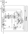
- FIG. 1 schematically shows a moving picture encoding apparatus 100 according to the first embodiment.
- the moving image encoding apparatus 100 includes a subtraction unit 101, an orthogonal transform unit 102, a quantization unit 103, an inverse quantization unit 104, an inverse orthogonal transform unit 105, an addition unit 106, a reference image memory. 107, an inter prediction unit 108, a motion information memory 109, a predicted motion information acquisition unit 110, a motion detection unit 111, a motion information selection switch 112, and an entropy encoding unit 113.
- the moving image encoding apparatus 100 can also be realized by causing a computer to execute an image encoding program.
- the encoding control unit 120 that controls the moving image encoding device 100 and the output buffer 130 that temporarily stores the encoded data 163 output from the moving image encoding device 100 are usually included in the moving image encoding device 100. Provided outside. Note that the video encoding device 100 may include the encoding control unit 120 and the output buffer 130.
- the encoding control unit 120 controls overall encoding processing of the moving image encoding apparatus 100 such as feedback control of generated code amount, quantization control, prediction mode control, and entropy encoding control. Specifically, the encoding control unit 120 provides the encoding control information 170 to the moving image encoding device 100, and appropriately receives feedback information 171 from the moving image encoding device 100.
- the encoding control information 170 includes prediction information, motion information, quantization information, and the like.
- the prediction information includes prediction mode information and block size information.
- the motion information includes a motion vector, a reference frame number, and a prediction direction (unidirectional prediction, bidirectional prediction).
- the quantization information includes a quantization parameter and a quantization matrix.
- the feedback information 171 includes information related to the generated code amount in the moving image encoding apparatus 100. The generated code amount is used, for example, to determine a quantization parameter.
- the moving image encoding apparatus 100 divides each frame (or field, slice) constituting the input image signal 151 into a plurality of pixel blocks, performs predictive encoding for each divided pixel block, and encodes the encoded data 163. Is generated.
- the moving image encoding apparatus 100 further includes a dividing unit (not shown) that divides the input image signal 151 into a plurality of pixel blocks.
- the dividing unit supplies a plurality of pixel blocks obtained by dividing the input image signal 151 to the subtracting unit 101 in a predetermined order. In the present embodiment, as illustrated in FIG.
- predictive encoding is performed on pixel blocks in raster scan order, that is, in the order from the upper left to the lower right of the encoding target frame 201.
- the encoded pixel block is positioned on the left side and the upper side of the encoding target block 202 in the encoding target frame 201.
- the encoding target block 202 indicates a pixel block that is supplied to the subtraction unit 101 and is an object of encoding processing, and the encoding target frame indicates a frame to which the encoding target block belongs.
- the encoded region 203 composed of encoded pixel blocks is indicated by hatching.
- the area 204 other than the encoded area 203 is an uncoded area.
- the pixel blocks used in this specification are, for example, coded images such as L ⁇ M size blocks (L and M are natural numbers), coding tree units, macroblocks, sub-blocks, one pixel, and the like. Refers to the processing unit to be converted.
- a pixel block is basically used in the sense of a coding tree unit.
- the pixel block can be interpreted in the above-described meaning by appropriately reading the description.
- the encoding processing unit is not limited to an example of a pixel block such as a coding tree unit, and a frame, a field, a slice, or a combination thereof can be used.
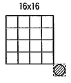
- the coding tree unit is a 16 ⁇ 16 pixel block shown in FIG. 3A.
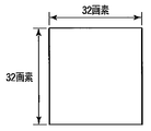
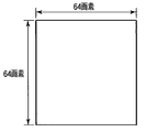
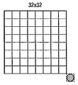
- the coding tree unit may be a 32 ⁇ 32 pixel block shown in FIG. 3B, a 64 ⁇ 64 pixel block shown in FIG. 3C, an 8 ⁇ 8 pixel block not shown, or a 4 ⁇ 4 pixel block not shown.
- the coding tree unit is not necessarily a square pixel block.
- the encoding target block or coding tree unit of the input image signal 151 may be referred to as a “prediction target block”.
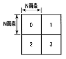
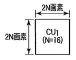
- FIG. 4A shows a coding tree unit CU 0 having a block size of 64 pixels ⁇ 64 pixels as an example of the coding tree unit.
- the coding tree unit CU 0 has a quadtree structure. That is, the coding tree unit CU 0 can be recursively divided into four pixel blocks.
- a natural number N representing the size of a standard coding tree unit is introduced, and the size of each pixel block obtained by quadtree division is defined as N pixels ⁇ N pixels. If defined in this way, the size of the coding tree unit before the quadtree division is expressed as 2N pixels ⁇ 2N pixels.
- N 32.
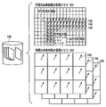
- FIG. 4B shows an example of quadtree partitioning of the coding tree unit CU 0 of FIG. 4A.
- Four pixel blocks (coding tree units) obtained by quadtree division are indexed in the Z-scan order.
- the numbers shown in each pixel block in FIG. 4B indicate the order of Z scanning.
- Each of the pixel blocks obtained by dividing the quadtree can be further divided into quadtrees.
- the depth of division is represented by Depth.
- This coding tree unit CU 1 corresponds to one of four pixel blocks obtained by dividing the coding tree unit CU 0 of FIG. 4A by quadtree division.
- the largest coding tree unit among these coding tree units is referred to as a large coding tree unit or tree block.
- the input image signal 151 is encoded in this unit in the raster scan order.
- the large coding tree unit is not limited to the 64 ⁇ 64 pixel block example, and may be any size pixel block.
- the minimum coding tree unit is not limited to an example of an 8 ⁇ 8 pixel block, and may be a pixel block of any size as long as it is smaller than the large coding tree unit.
- the 1 encodes the input image signal 151 by selectively applying a plurality of prediction modes having different block sizes and methods of generating the predicted image signal 159, respectively.
- the generation method of the predicted image signal 159 is roughly classified into intra prediction that performs prediction within the encoding target frame, and prediction using one or a plurality of reference frames (encoded frames) that are temporally different.
- the video encoding apparatus 100 performs inter prediction or intra prediction on each pixel block obtained by dividing the input image signal 151 based on the encoding parameter given from the encoding control unit 120, and performs prediction corresponding to the pixel block.
- An image signal 159 is generated.
- Inter prediction is also referred to as inter-screen prediction, inter-frame prediction, motion compensation prediction, and the like.
- Intra prediction is also referred to as intra prediction, intra frame prediction, and the like.
- the moving image encoding apparatus 100 selectively uses an inter prediction unit 108 that performs inter prediction or an intra prediction unit (not shown) that performs intra prediction, and thereby predicts a predicted image signal corresponding to a pixel block. 159 is generated.
- the moving image coding apparatus 100 performs orthogonal transform and quantization on the prediction error signal 152 representing the difference between the pixel block and the predicted image signal 159 to generate a quantized transform coefficient 154. Furthermore, the moving image encoding apparatus 100 performs entropy encoding on the quantized transform coefficient 154 to generate encoded data 163.
- the subtraction unit 101 generates a prediction error signal 152 by subtracting the corresponding prediction image signal 159 from the encoding target block of the input image signal 151.
- the subtraction unit 101 outputs the prediction error signal 152 to the orthogonal transformation unit 102.
- the orthogonal transformation unit 102 performs orthogonal transformation on the prediction error signal 152 from the subtraction unit 101 to generate a transformation coefficient 153.
- the orthogonal transform for example, discrete cosine transform (DCT: Discrete Cosine Transform), Hadamard transform, wavelet transform, independent component analysis, or the like can be used.
- the orthogonal transform unit 102 outputs the transform coefficient 153 to the quantization unit 103.
- the quantization unit 103 quantizes the transform coefficient 153 from the orthogonal transform unit 102 to generate a quantized transform coefficient 154. Specifically, the quantization unit 103 quantizes the transform coefficient 153 according to quantization information including a quantization parameter, a quantization matrix, and the like. A quantization parameter and a quantization matrix required for quantization are specified by the encoding control unit 120. The quantization parameter indicates the fineness of quantization. The quantization matrix is used for weighting the fineness of quantization for each component of the transform coefficient. The quantization matrix is not necessarily used. The use or non-use of the quantization matrix is not an essential part of the embodiment. The quantization unit 103 outputs the quantized transform coefficient 154 to the entropy coding unit 113 and the inverse quantization unit 104.
- the entropy encoding unit 113 includes a quantization transform coefficient 154 from the quantization unit 103, motion information 160 from a motion information selection switch 112 described later, and prediction information and quantization information specified by the encoding control unit 120.
- Entropy coding (for example, Huffman coding, arithmetic coding, etc.) is performed on the coding parameters.
- the encoding parameter is a parameter necessary for decoding, and includes prediction information, motion information 160, information on transform coefficients (quantized transform coefficient 154), information on quantization (quantization information), and the like.
- the encoding control unit 120 includes an internal memory (not shown), and the encoding parameters are held in this memory.
- For encoding of the prediction target block an encoded pixel block adjacent to the prediction target block is used. Applied coding parameters can be used.
- FIG. 5 shows the entropy encoding unit 113 in more detail.
- the entropy encoding unit 113 includes a parameter encoding unit 501, a transform coefficient encoding unit 502, a motion information encoding unit 503, and a multiplexing unit 504.
- the parameter encoding unit 501 encodes the encoding parameter included in the encoding control information 170 from the encoding control unit 120 to generate encoded data 551.
- the encoding parameters encoded by the parameter encoding unit 501 include prediction information and quantization information.
- the transform coefficient encoding unit 502 encodes the quantized transform coefficient 154 received from the quantization unit 103 to generate encoded data 552.
- the motion information encoding unit 503 refers to the prediction motion information 167 received from the prediction motion information acquisition unit 110 and the prediction motion information position included in the encoding control information 170 from the encoding control unit 120, and the inter prediction unit
- the motion information 160 applied to 108 is encoded to generate encoded data 553.
- the motion information encoding unit 503 will be described in detail later.
- the multiplexing unit 504 generates encoded data 163 by multiplexing the encoded data 551, 552, and 553.
- the generated encoded data 163 includes all parameters necessary for decoding, such as motion information 160, prediction information, information on transform coefficients (quantized transform coefficients 154), and quantized information.
- the encoded data 163 generated by the entropy encoding unit 113 is temporarily stored in the output buffer 130 and output according to an appropriate output timing managed by the encoding control unit 120.
- the encoded data 163 is sent to, for example, a storage system (storage medium) or a transmission system (communication line) not shown.
- the inverse quantization unit 104 inversely quantizes the quantized transform coefficient 154 received from the quantizing unit 103 to generate a restored transform coefficient 155. Specifically, the inverse quantization unit 104 inversely quantizes the quantization transform coefficient 154 in accordance with the same quantization information as the quantization information used in the quantization unit 103. The quantization information used by the inverse quantization unit 104 is loaded from the internal memory of the encoding control unit 120. The inverse quantization unit 104 outputs the restored transform coefficient 155 to the inverse orthogonal transform unit 105.
- the inverse orthogonal transform unit 105 performs inverse orthogonal transform corresponding to the orthogonal transform performed in the orthogonal transform unit 102 on the reconstructed transform coefficient 155 from the inverse quantization unit 104, and generates a reconstructed prediction error signal 156.
- the orthogonal transform in the orthogonal transform unit 102 is discrete cosine transform (DCT)
- the inverse orthogonal transform unit 105 performs inverse discrete cosine transform (IDCT: Inverse Discrete Cosine Transform).
- IDCT Inverse Discrete Cosine Transform
- the addition unit 106 adds the restored prediction error signal 156 and the corresponding predicted image signal 159 to generate a local decoded image signal 157.
- the decoded image signal 157 is sent to the reference image memory 107 after filtering processing.
- a deblocking filter or a Wiener filter is used for filtering the decoded image signal 157.
- the reference image memory 107 stores the decoded image signal 157 after the filtering process.
- the decoded image signal 157 stored in the reference image memory 107 is referred to as a reference image signal 158 by the inter prediction unit 108 as necessary in order to generate a predicted image.
- the inter prediction unit 108 performs inter prediction using the reference image signal 158 stored in the reference image memory 107. Specifically, the inter prediction unit 108 performs motion compensation (when motion compensation with small-pixel accuracy is possible) based on the motion information 160 indicating the amount of motion shift between the prediction target block and the reference image signal 158. Performs an interpolating process) to generate an inter predicted image. For example, H.M. With H.264, interpolation processing up to 1/4 pixel accuracy is possible.
- the motion information memory 109 temporarily stores the motion information 160 as reference motion information 166.
- the amount of information may be reduced by performing compression processing such as sub-sampling on the motion information 160.
- the reference motion information 166 is held in units of frames (or slices).
- the motion information memory 109 includes a spatial direction reference motion information memory 601 that stores motion information 160 of an encoding target frame as reference motion information 166, and an already encoded frame. And a time direction reference motion information memory 602 that stores the motion information 160 as reference motion information 166.
- the time direction reference motion information memory 602 can be prepared in a number corresponding to the number of reference frames used for prediction of the encoding target frame.
- the spatial direction reference motion information memory 601 and the temporal direction reference motion information memory 602 may be provided on the same memory by logically dividing the physically same memory. Furthermore, the spatial direction reference motion information memory 601 holds only the spatial direction motion information necessary for encoding the encoding target frame, and the spatial direction motion that is no longer referred to in the encoding of the encoding target frame. The information may be sequentially compressed and stored in the time direction reference motion information memory 602.
- the reference motion information 166 is held in the spatial direction reference motion information memory 601 and the temporal direction reference motion information memory 602 in a predetermined region unit (for example, 4 ⁇ 4 pixel block unit).
- the reference motion information 166 further includes information indicating whether inter prediction or intra prediction is applied to the region.
- the value of the motion vector in the motion information 160 is not encoded. Even when a coding tree unit (or prediction unit) is subjected to inter prediction using motion information 160 predicted or obtained from an encoded region according to such a mode, the coding tree unit (or prediction) Unit) motion information 160 is held as reference motion information 166.
- the spatial direction reference motion information memory 601 that holds the reference motion information 166 related to this frame is used as the temporal direction reference motion information memory 602 used for the frame to be encoded next.
- the handling will be changed.
- the reference motion information 166 may be compressed, and the compressed reference motion information 160 may be stored in the time direction reference motion information memory 602.
- the temporal direction reference motion information memory 602 can hold the reference motion information 166 in units of 16 ⁇ 16 pixel blocks.
- the predicted motion information acquisition unit 110 refers to the reference motion information 166 held in the motion information memory 109, and the motion information candidate 160 ⁇ / b> A used for the encoding target prediction unit and the entropy code
- the prediction unit 113 generates predicted motion information 167 used for differential encoding of motion information.
- the predicted motion information acquisition unit 110 will be described in detail later.
- the motion detection unit 111 generates a motion vector by performing processing such as block matching between the prediction target block and the reference image signal 158, and outputs motion information including the generated motion vector as a motion information candidate 160B.
- the motion information selection switch 112 is a motion information candidate 160A output from the predicted motion information acquisition unit 110 and a motion output from the motion detection unit 111 according to the prediction information included in the encoding control information 170 from the encoding control unit 120. One of the information candidates 160B is selected.
- the motion information selection switch 112 outputs the selected information as motion information 160 to the inter prediction unit 108, the motion information memory 109, and the entropy encoding unit 113.
- the prediction information conforms to a prediction mode controlled by the encoding control unit 120, and which of switching information for controlling the motion information selection switch 112 and inter prediction or intra prediction is applied to generate the prediction image signal 159.
- the selection information indicating is included.
- the encoding control unit 120 determines which of the motion information candidate 160A and the motion information candidate 160B is optimal, and generates switching information according to the determination result. Also, the encoding control unit 120 determines which prediction mode is the optimal prediction mode from among a plurality of prediction modes of intra prediction and inter prediction, and generates selection information indicating the optimal prediction mode. For example, the encoding control unit 120 determines an optimal prediction mode using a cost function shown in the following mathematical formula (1).
- OH represents a code amount related to prediction information (for example, motion vector information and prediction block size information)
- SAD represents a sum of absolute differences (ie, prediction) between the prediction target block and the prediction image signal 159.
- ⁇ represents a Lagrange undetermined multiplier determined based on the value of quantization information (quantization parameter)
- K represents an encoding cost.
- the prediction mode that minimizes the coding cost (also referred to as simple coding cost) K is determined as the optimal prediction mode from the viewpoint of the amount of generated code and prediction error.
- the simple coding cost is not limited to the example of Equation (1), and may be estimated from only the code amount OH or the difference absolute value sum SAD, or a value obtained by performing Hadamard transform on the difference absolute value sum SAD. Or you may estimate using the approximate value.
- the encoding control unit 120 determines an optimal prediction mode using a cost function shown in the following mathematical formula (2).
- Equation (2) D represents a square error sum between the prediction target block and the locally decoded image, that is, encoding distortion, and R represents a prediction error between the prediction target block and the prediction image signal 159 in the prediction mode.
- J indicates the encoding cost.
- the detailed coding cost is not limited to the example of Equation (2), but may be estimated from only the code amount R or the coding distortion D, or an approximate value of the code amount R or the coding distortion D is used. And may be estimated. Further, these cost functions may be used hierarchically.
- the encoding control unit 120 uses Equation (1) or Equation (2) based on information obtained in advance regarding the prediction target block (for example, prediction modes of surrounding pixel blocks, results of image analysis, and the like). The number of prediction mode candidates to be determined can be narrowed down in advance.
- the number of prediction mode candidates can be further reduced while maintaining encoding performance by performing two-stage mode determination combining Formula (1) and Formula (2). It becomes.
- the simple encoding cost represented by the formula (1) does not require a local decoding process, and can be calculated at high speed. H.
- mode determination using only the detailed coding cost J may cause a processing delay. Therefore, in the first step, the encoding control unit 120 calculates a simple encoding cost K related to the prediction mode that can be used for the pixel block, and selects a prediction mode candidate from the available prediction modes.
- the encoding control unit 120 calculates the detailed encoding cost J for the prediction mode candidate, and determines the prediction mode candidate that minimizes the detailed encoding cost J as the optimal prediction mode.
- the number of prediction mode candidates using the property that the correlation between the simple coding cost and the detailed coding cost increases as the value of the quantization parameter that determines the roughness of quantization increases. it can.
- a plurality of prediction modes are prepared in the moving image encoding apparatus 100 of FIG. 1, and the generation method of the predicted image signal 159 and the motion compensation block size are different in each prediction mode.
- the inter prediction unit 108 As a method for the inter prediction unit 108 to generate the predicted image signal 159, there is inter prediction in which a predicted image is generated using the reference image signal 158 of one or more encoded reference frames (or reference fields).
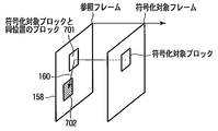
- Inter prediction will be described with reference to FIG. 7A.
- Inter prediction is typically performed in units of prediction units, and may have different motion information 160 in units of prediction units.
- inter prediction as shown in FIG. 7A, a pixel block in a reference frame that has already been encoded (for example, an encoded frame one frame before), and a block at the same position as the encoding target prediction unit From 701, a predicted image signal 159 is generated using the reference image signal 158 of the block 702 at a position spatially shifted according to the motion vector included in the motion information 160. That is, in the generation of the predicted image signal 159, the reference image signal 158 of the block in the reference frame specified by the position (coordinates) of the encoding target block and the motion vector included in the motion information 160 is used.
- inter prediction motion compensation with small pixel accuracy (for example, 1/2 pixel accuracy or 1/4 pixel accuracy) is possible, and a value of an interpolated pixel is generated by performing filtering processing on the reference image signal 158.
- filtering processing for example, 1/2 pixel accuracy or 1/4 pixel accuracy
- H.M. In H.264, it is possible to perform interpolation processing up to 1/4 pixel accuracy on the luminance signal. This interpolation process is described in H.264. It may be performed using any filtering other than the filtering defined in H.264.
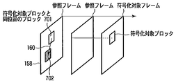
- the reference frame is not limited to the example of using the reference frame one frame before as shown in FIG. 7A, and any reference frame may be used as long as it is already encoded.
- a reference frame two frames before the encoding target frame can be used for inter prediction.
- reference image signals 158 of a plurality of reference frames having different time positions are held in the reference image memory 107, information indicating which time position of the reference image signal 159 generated the predicted image signal 159 is a reference frame number. It is represented by The reference frame number is included in the motion information 160.
- the reference frame number can be changed in region units (picture, slice, block unit, etc.). That is, a different reference frame can be used for each prediction unit.
- the reference frame number of this region is set to 0, and when the encoded reference frame two frames before is used for prediction, The reference frame number of this area is set to 1.
- the reference image signal 158 for only one frame is held in the reference image memory 107 (the number of reference frames held is only one), the reference frame number is always 0. Is set.
- a size suitable for a block to be encoded can be selected and used from the sizes of a plurality of prediction units prepared in advance. For example, as shown in FIGS. 8A to 8G, motion compensation can be performed for each prediction unit obtained by dividing a coding tree unit.
- FIG. 8A shows an example in which the prediction unit and the coding tree unit are the same size. In this case, there is one prediction unit PU 0 in the coding tree unit.
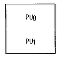
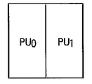
- FIGS. 8B to 8I respectively show examples in which a plurality of prediction units exist in the coding tree unit. 8B and 8C, there are two prediction units PU 0 and PU 1 in the coding tree unit.
- prediction units PU 0 and PU 1 are blocks obtained by dividing a coding tree unit into two in the vertical direction.
- FIG. 8C prediction units PU 0 and PU 1 are divided into two coding tree units horizontally.
- FIG. 8D shows an example in which the prediction unit is a block obtained by dividing the coding tree unit into four.
- the block sizes of a plurality of prediction units existing in the coding tree unit may be different from each other.
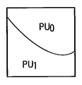
- the prediction unit is not limited to the rectangular shape, and is a block having a shape obtained by dividing the coding tree unit by an arbitrary line segment or a curve such as an arc as shown in FIGS. 8F and 8G. There may be.
- the motion information 160 of the encoded pixel block (for example, 4 ⁇ 4 pixel block) in the encoding target frame used for the inter prediction is held in the motion information memory 109 as the reference motion information 166. Yes.
- the optimal motion compensation block shape, motion vector, and reference frame number can be used in accordance with the local nature of the input image signal 151.
- the coding tree unit and the prediction unit can be arbitrarily combined. As described above, when the coding tree unit is a 64 ⁇ 64 pixel block, four coding tree units are further added to each of the four coding tree units (32 ⁇ 32 pixel block) obtained by dividing the 64 ⁇ 64 pixel block.
- pixel blocks from 64 ⁇ 64 pixel blocks to 16 ⁇ 16 pixel blocks can be used hierarchically.
- pixel blocks from 64 ⁇ 64 pixel blocks to 8 ⁇ 8 pixel blocks can be used hierarchically.
- the prediction unit is obtained by dividing the coding tree unit into four, it is possible to execute a hierarchical motion compensation process from a 64 ⁇ 64 pixel block to a 4 ⁇ 4 pixel block. .
- bi-directional prediction using two types of motion compensation can be performed on the encoding target block.
- H.264 bidirectional prediction two types of motion compensation are performed on the encoding target block to generate two types of predicted image signals, and a weighted average of these two types of predicted image signals is used to generate a new predicted image signal. obtain.
- Two types of motion compensation in bidirectional prediction are referred to as list 0 prediction and list 1 prediction, respectively.
- the moving picture encoding apparatus 100 uses a plurality of prediction modes with different encoding processes shown in FIG.
- the skip mode is a mode in which only syntax related to the predicted motion information position is encoded and other syntax is not encoded.
- the merge mode is a mode in which syntax related to the predicted motion information position and information related to the transform coefficient are encoded and other syntax is not encoded.
- the inter mode is a mode for encoding syntax regarding the predicted motion information position, differential motion information, and information regarding the transform coefficient. These modes are switched according to prediction information controlled by the encoding control unit 120.
- FIG. 10 shows the predicted motion information acquisition unit 110 in more detail.
- the predicted motion information acquisition unit 110 includes a reference motion information acquisition unit 1001, motion information setting units 1002-1 to 1002-W, and a predicted motion information selection switch 1003.
- W represents the number of predicted motion information candidates generated by the reference motion information acquisition unit 1001.
- the reference motion information acquisition unit 1001 acquires the reference motion information 166 from the motion information memory 109.
- the reference motion information acquisition unit 1001 uses the acquired reference motion information 166 to generate one or more predicted motion information candidates 1051-1, 1051-2,.
- the predicted motion information candidate is also referred to as a predicted motion vector candidate.
- Prediction motion information setting sections 1002-1 to 1002-W receive prediction motion information candidates 1051-1 to 1051-W from reference motion information acquisition section 1001, respectively, and apply a prediction method (unidirectional) to the prediction target prediction unit. Prediction, bi-directional prediction) and reference frame number setting and motion vector information scaling are performed to generate modified predicted motion information candidates 1052-1 to 1052-W, respectively.
- the predicted motion information selection switch 1003 selects one of the one or more modified predicted motion information candidates 1052-1 to 1052-W according to a command included in the encoding control information 170 from the encoding control unit 120. Then, the predicted motion information selection switch 1003 outputs the selected motion information candidate 160A to the motion information selection switch 112 and also outputs the predicted motion information 167 used for differential encoding of motion information in the entropy encoding unit 113. . Typically, the motion information candidate 160A and the predicted motion information 167 include the same motion information, but may include different motion information in accordance with an instruction from the encoding control unit 120. Note that the predicted motion information selection switch 1003 may output predicted motion information position information, which will be described later, instead of the encoding control unit 120. The encoding control unit 120 determines which of the corrected predicted motion information candidates 1052-1 to 1052-W is to be selected using an evaluation function such as Expression (1) or Expression (2).
- the list 0 predicted motion information candidate held by the motion information candidate 160A is the list 1 predicted motion information candidate. May be copied.
- the reference motion information 166 including the list 0 predicted motion information and the list 1 predicted motion information, which is the same information as the list 0 predicted motion information, is used when the subsequent prediction unit is encoded.
- the reference motion information 166 is used by the predicted motion information acquisition unit 110.
- each of the predicted motion information setting units 1002-1 to 1002-W, the predicted motion information candidates 1051-1 to 1051-W, and the modified predicted motion information candidates 1052-1 to 1052-W will be described without particular distinction.
- the numbers at the end of the reference signs (“ ⁇ 1” to “ ⁇ W”) are omitted, and are simply described as the predicted motion information setting unit 1002, the predicted motion information candidate 1051, and the corrected predicted motion information candidate 1052.
- FIGS. 11A, 11B, and 12 illustrate examples of positions of adjacent prediction units that are referred to by the reference motion information acquisition unit 1001 to generate the predicted motion information candidate 1051.
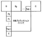
- FIG. FIG. 11A shows an example in which a prediction unit spatially adjacent to an encoding target prediction unit is set as an adjacent prediction unit.
- Block C, block D, and block E indicate prediction units adjacent to the encoding target prediction unit on the upper right, upper left, and lower left, respectively.
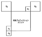
- FIG. 11B shows another example in which a prediction unit spatially adjacent to the encoding target prediction unit is set as an adjacent prediction unit.
- adjacent prediction units A 0 and A 1 are located at the lower left and the left of the encoding target prediction unit, respectively.
- the adjacent prediction units B 0 , B 1 and B 2 are located at the upper right, upper and upper left of the encoding target prediction unit, respectively.
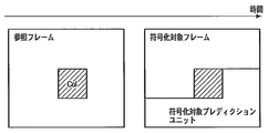
- FIG. 12 shows an example in which the prediction unit (prediction unit in the encoded reference frame) that is temporally adjacent to the encoding target prediction unit is set as the adjacent prediction unit.
- the adjacent prediction unit shown in FIG. 12 is a prediction unit in a reference frame located at the same coordinate as the encoding target prediction unit.
- the position of this adjacent prediction unit is represented as position Col.
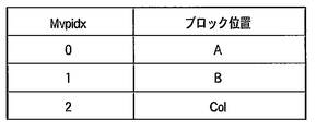
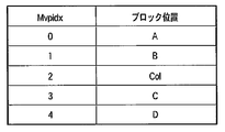
- FIG. 13A illustrates an example of a list indicating the relationship between the block position and the block position index Mvpidx that the reference motion information acquisition unit 1001 refers to in order to generate the predicted motion vector candidate 1051.
- the block position A is determined as the position of the adjacent prediction unit having the smallest value of X among the selected adjacent prediction units.
- the motion vector predictor candidate 1051 whose block position index Mvpidx is 0 is generated from the reference motion information of the adjacent prediction unit at the block position A located in the spatial direction.
- a motion vector predictor candidate 1051 whose block position index Mvpidx is 1 is generated from the reference motion information of the adjacent prediction unit at the block position B located in the spatial direction.
- the predicted motion vector candidate 1051 whose block position index Mvpidx is 2 is generated from the reference motion information 166 of the adjacent prediction unit at the position Col in the reference frame.
- the motion vector predictor candidate whose index Mvpidx is 0 corresponds to the motion vector predictor candidate 1051-1 shown in FIG.
- a motion vector predictor candidate whose index Mvpidx is 1 corresponds to the motion vector predictor candidate 1051-2
- a motion vector predictor candidate whose index Mvpidx is 3 corresponds to the motion vector predictor candidate 1051-3.
- FIG. 13B shows another example of a list indicating the relationship between the block position and the block position index Mvpidx that the reference motion information acquisition unit 1001 refers to in order to generate the predicted motion vector candidate 1051.
- Block positions C and D refer to the positions of adjacent prediction units C and D shown in FIG. 12A, for example.
- the reference motion information 166 of the adjacent prediction unit at the block position D is replaced with the reference motion information 166 of the adjacent prediction unit at the block position C.
- the reference motion information 166 of the adjacent prediction unit at the block position E is replaced with the reference motion information 166 at the prediction unit position C.
- a plurality of motion information prediction candidates may be generated from a plurality of adjacent prediction units located in the time direction.
- the block position Col (C3) shown in FIG. 13C indicates the position of the prediction unit at a predetermined position in the adjacent prediction unit of the block position Col, as will be described later with reference to FIGS. 14A to 16F.
- the block position Col (H) shown in FIG. 13C indicates the position of the prediction unit at a predetermined position outside the adjacent prediction unit at the block position Col, as will be described later with reference to FIGS. 17A to 17F. Show.
- the adjacent prediction unit at the block position Col receives the plurality of reference motion information 166 in the time direction.
- the reference motion information memory 602 may hold the information.
- the reference motion information acquisition unit 1001 acquires one reference motion information 166 from the plurality of reference motion information 166 held in the adjacent prediction unit at the block position Col according to a predetermined method.
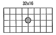
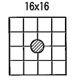
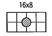
- the acquisition position of the reference motion information in the adjacent prediction unit at the block position Col is referred to as a reference motion information acquisition position.
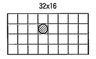
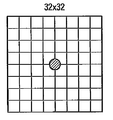
- each block indicates a 4 ⁇ 4 prediction unit
- a circle indicates a reference motion information acquisition position.
- the reference motion information 166 of the 4 ⁇ 4 prediction unit indicated by a circle is used as a position prediction motion information candidate.
- the reference motion information acquisition unit 1001 sets the predicted motion information candidate 1051 according to a predetermined method. Generate. As an example, the reference motion information acquisition unit 1001 calculates an average value or median value of reference motion information of four 4 ⁇ 4 prediction units adjacent to the reference motion information acquisition position, and uses the calculated average value or median value as predicted motion information. A candidate 1051 is generated.
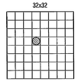
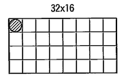
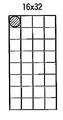
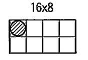
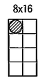
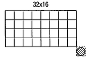
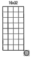
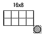
- 16A to 16F show an example in which the reference motion information acquisition position is set at the upper left corner in the adjacent prediction unit at the position Col. 16A to 16F, the encoding target prediction unit is a 32 ⁇ 32 pixel block, a 32 ⁇ 16 pixel block, a 16 ⁇ 32 pixel block, a 16 ⁇ 16 pixel block, a 16 ⁇ 8 pixel block, and an 8 ⁇ 16 pixel block.
- the reference motion information of the 4 ⁇ 4 prediction unit located at the upper left corner of the adjacent prediction unit at the block position Col is used as a predicted motion information candidate.
- the method of generating the predicted motion information candidate 1051 with reference to the prediction unit in the reference frame is not limited to the method shown in FIGS. 14A to 16F, and any method may be used as long as it is a predetermined method. .
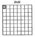
- the position outside the adjacent prediction unit at the block position Col may be set as the reference motion information acquisition position.
- the encoding target prediction unit is a 32 ⁇ 32 pixel block, a 32 ⁇ 16 pixel block, a 16 ⁇ 32 pixel block, a 16 ⁇ 16 pixel block, a 16 ⁇ 8 pixel block, and an 8 ⁇ 16 pixel block. Correspond to each.
- the reference motion information acquisition position indicated by a circle is set to the position of the 4 ⁇ 4 prediction unit circumscribing the lower right of the adjacent prediction unit at the block position Col. If this 4x4 prediction unit is out of the screen or cannot be referred to because no inter prediction is applied, the prediction unit at the reference motion information acquisition position shown in FIGS. 14A to 16F is used instead. Reference may be made.
- the reference motion information acquisition unit 1001 If the adjacent prediction unit does not have the reference motion information 166, the reference motion information acquisition unit 1001 generates reference motion information having a zero vector as the predicted motion information candidate 1051.
- the reference motion information acquisition unit (also referred to as a predicted motion information candidate generation unit) 1001 refers to the motion information memory 109 and generates one or more predicted motion information candidates 1051-1 to 1051-W.
- An adjacent prediction unit referred to for generation of a predicted motion information candidate that is, an adjacent prediction unit from which a predicted motion information candidate is acquired or output is referred to as a reference motion block.
- the predicted motion information candidate 1051 is a list 0 predicted motion information candidate used for list 0 prediction and a list 1 predicted motion information candidate used for list 1 prediction.
- the predicted motion information candidate 1051 includes both the list 0 predicted motion information candidate and the list 1 predicted motion information candidate.
- FIG. 18 shows an example of processing of the predicted motion information setting unit 1002.
- the predicted motion information setting unit 1002 determines whether the predicted motion information candidate 1051 is output from a spatial reference motion block or is output from a temporal reference motion block. Is determined (step S1801).
- the predicted motion information setting unit 1002 outputs the predicted motion information candidate 1051 as the corrected predicted motion information candidate 1052. (Step S1812).
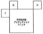
- the prediction motion information setting unit 1002 includes the prediction direction to be applied to the encoding target prediction unit and A reference frame number is set (step S1802). Specifically, when the encoding target prediction unit is a pixel block in a P slice to which only unidirectional prediction is applied, the prediction direction is set to unidirectional prediction. Furthermore, when the prediction target encoding unit is a pixel block in a B slice to which unidirectional prediction and bidirectional prediction can be applied, the prediction direction is set to bidirectional prediction.
- the reference frame number is set with reference to an encoded adjacent prediction unit located in the spatial direction.
- FIG. 19 illustrates the position of the adjacent prediction unit used for setting the reference frame number.
- adjacent prediction units F, G, and H are encoded prediction units that are adjacent to the encoding target prediction unit on the left, upper, and upper right, respectively.
- the reference frame number is determined by majority using the reference frame numbers of the adjacent prediction units F, G, and H. As described above, the reference frame number is included in the reference motion information. As an example, when the reference frame numbers of adjacent prediction units F, G, and H are 0, 1, and 1, respectively, the reference frame number of the encoding target prediction unit is set to 1.
- the reference frame number of the encoding target prediction unit is set to the smallest reference frame number among these reference frame numbers. Furthermore, if the adjacent prediction units F, G and H are not applied with inter prediction, or because the adjacent prediction units F, G and H are located outside the frame or slice, the adjacent prediction units F, G When H and H cannot be referred to, the reference frame number of the encoding target prediction unit is set to 0. In other embodiments, the reference frame number of the target prediction unit may be set using one of the neighboring prediction units F, G, and H, or a fixed value (eg, zero). May be set.
- the process of step S1802 is performed for the list 0 prediction when the slice to which the encoding target prediction unit belongs is a P slice, and is performed for both the list 0 prediction and the list 1 prediction when the slice is a B slice. Is called.
- the predicted motion information setting unit 1002 determines whether or not the slice to which the encoding target prediction unit belongs (also referred to as an encoded slice) is a B slice (step S1803).
- the encoded slice is not a B slice, that is, a P slice (the determination in step S1803 is NO)
- the predicted motion information candidate 1051 includes one of a list 0 predicted motion information candidate and a list 1 predicted motion information candidate.
- the predicted motion information setting unit 1002 scales motion vectors included in the list 0 predicted motion information candidate or the list 1 predicted motion information candidate using the reference frame number set in step S1802 (step S1810). Further, the predicted motion information setting unit 1002 outputs the list 0 predicted motion information candidate or the list 1 predicted motion information candidate including the scaled motion vector as the modified predicted motion information candidate 1052 (step S1811).
- the motion vector predictor setting unit 1002 determines whether or not the unidirectional prediction is applied to the reference motion block (step S1804).
- the unidirectional prediction is applied to the reference motion block (the determination in step S1804 is YES)
- the predicted motion information setting unit 1002 displays the list 0.
- the predicted motion information candidate is copied to the list 1 predicted motion information candidate (step S1805). If bi-directional prediction is applied to the reference motion block (the determination in step S1804 is NO), the process skips step S1805 and proceeds to step S1806.
- the predicted motion information setting unit 1002 scales the motion vector of the list 0 predicted motion information candidate and the motion vector of the list 1 predicted motion information candidate using the reference frame number set in step S1802 (step S1806). ). Next, the predicted motion information setting unit 1002 determines whether the block referred to by the list 0 predicted motion information candidate and the block referred to by the list 1 predicted motion information candidate are the same (step S1807).
- the predicted motion information setting unit 1002 changes the prediction direction from bidirectional prediction to unidirectional prediction, and outputs a corrected predicted motion information candidate 1052 including only the list 0 predicted motion information candidate (step S1808).
- the prediction direction is changed from bidirectional prediction to unidirectional prediction. Motion compensation processing and average processing in prediction can be reduced.
- the predicted motion information setting unit 1002 performs bidirectional prediction on the prediction direction. And the corrected predicted motion information candidate 1052 including the list 0 predicted motion information candidate and the list 1 predicted motion information candidate is output (step S1809).
- the predicted motion information setting unit 1002 corrects the predicted motion information candidate 1051 and generates a corrected predicted motion information candidate 1052.
- the motion information of the encoding target prediction unit is set using the motion information of the encoded pixel block, and the list 0 prediction is performed.
- the motion compensation processing and the average processing in the inter prediction are reduced by setting the prediction direction to unidirectional prediction. be able to. As a result, the processing amount in inter prediction can be reduced.
- Steps S2001 to S2006 and S2010 to S2012 in FIG. 20 are the same as steps S1801 to 1806 and S1810 to S1812 shown in FIG.
- step S2007 the predicted motion information setting unit 1002 determines whether the block referred to by the list 0 predicted motion information candidate generated in steps S2001 to S2006 is the same as the block referred to by the list 1 predicted motion information candidate. To do.
- a predicted value (predicted image) generated by bidirectional prediction Is equivalent to a predicted value (predicted image) generated by unidirectional prediction. Therefore, the predicted motion information setting unit 1002 derives the list 1 predicted motion information candidate again from a position spatially different from the reference motion information acquisition position from which the list 1 predicted motion information candidate is derived (step S2008).
- the reference motion information acquisition position used at the start of the process shown in FIG. 20 is referred to as a first reference motion information acquisition position, and the reference motion information acquisition position used for deriving the reference motion information again in step S2008. This is referred to as a second reference motion information acquisition position.
- the first reference motion information acquisition position is set to a position circumscribing to the lower right of the prediction unit at the position Col in the reference frame, as indicated by a circle in FIG. 17A.
- the information acquisition position is set to a predetermined position in the prediction unit at the position Col in the same reference frame, as indicated by a circle in FIG. 14A.
- the first reference motion information acquisition position and the second reference motion information acquisition position may be set to positions shown in FIGS. 14A to 16F or positions not shown.
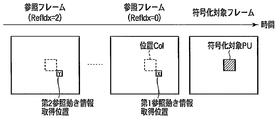
- FIG. 21A illustrates an example in which the first reference motion information acquisition position and the second reference motion information acquisition position are set to different reference frames in time.
- the first reference motion information acquisition position is set to the lower right position X of the prediction unit of the position Col in the reference frame whose reference frame number (RefIdx) is 0.
- the second reference motion information acquisition position Y is a position in the reference frame whose reference frame number is 1, and is set to the same position as the first reference motion information acquisition position X.
- the first reference motion information acquisition position and the second reference motion information acquisition position may be set at different positions in time and space.
- the second reference motion information acquisition position Y is a position in the reference frame whose reference frame number is 1, and is a predetermined position in the prediction located at the same coordinates as the encoding target prediction unit. Is set. Furthermore, as illustrated in FIG. 21C, the reference frame position to which the first reference motion information acquisition position belongs and the reference frame position to which the second reference motion information acquisition position belongs may be any time position. In FIG. 21C, the first reference motion information acquisition position X is set to a position on the reference frame whose reference frame number is 0, and the second reference motion information acquisition position Y is in the reference frame whose reference frame number is 2. And the same position as the first reference motion information acquisition position X.
- the motion information of the encoded prediction unit is set using the motion information of the encoded pixel block, and the list 0 prediction is performed. If the block referenced by the motion information in the list and the block referenced by the motion information in the list 1 prediction are the same, the motion information in the list 1 prediction is acquired by a method different from the method for acquiring the motion information in the list 0 prediction.
- bidirectional prediction having higher prediction efficiency than unidirectional prediction can be realized.
- the motion information acquisition position in the list 1 prediction is set to a position close to the position of the conventional acquisition position, two types of motion information suitable for bidirectional prediction can be acquired. Further, the prediction efficiency is improved.
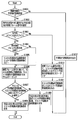
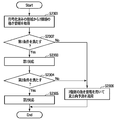
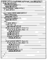
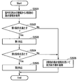
- the predicted motion information setting unit 1002 acquires two types of motion information (first predicted motion information and second predicted motion information) from the encoded region (step S2201).
- two types of motion information can be acquired from the reference motion information acquisition position described above.
- the frequency of motion information adapted to the encoding target prediction unit may be calculated so far, and the motion information with high frequency may be used. Motion information may be used.
- the predicted motion information setting unit 1002 determines whether or not the two types of motion information acquired in step S2201 satisfy the first condition (step S2202).
- the first condition includes at least one of the following conditions (A) to (F).
- (D) The motion vectors included in the two types of motion information are the same.
- E The absolute value of the difference between the motion vectors included in the two types of motion information is less than or equal to a predetermined threshold.
- step S2202 in which the number and configuration of the reference frames used for 0 prediction and list 1 prediction are the same, two or more types of motion information are the first when the conditions (A) to (F) are satisfied. It is determined that the condition is satisfied. Further, it may be determined that the first condition is always satisfied.
- a first condition that is the same as the first condition set in the moving picture decoding apparatus described in the second embodiment is set in the moving picture encoding apparatus 100. Alternatively, the first condition set in the video encoding device 100 may be transmitted to the video decoding device as additional information.
- the prediction target prediction unit is applied with bi-directional prediction without changing the two types of motion information (step S2104).
- the motion estimation information setting unit 1002 performs the first response (step S2203).
- the first correspondence includes one or more of the following correspondences (1) to (6). (1) The prediction method is set to unidirectional prediction, and one of the two types of motion information is output as a list 0 predicted motion information candidate.
- the prediction method is set to bidirectional prediction, and the motion information acquisition position To obtain motion information from spatially different block positions and output two types of motion information as list 0 predicted motion information candidates and list 1 predicted motion information candidates (3)
- Set the prediction method to bidirectional prediction The motion information is acquired from a block position that is temporally different from the acquisition position of the motion information, and two types of motion information are output as a list 0 predicted motion information candidate and a list 1 predicted motion information candidate.
- Bidirectional prediction is set, the reference frame number included in the motion information is changed, and two types of motion information are output as a list 0 predicted motion information candidate and a list 1 predicted motion information candidate.
- the measurement method is set to bidirectional prediction, the motion vector included in the motion information is changed, and two types of motion information are output as a list 0 predicted motion information candidate and a list 1 predicted motion information candidate (2) to ( 5) may be applied only to one of the two types of motion information, or may be applied to both pieces of motion information.
- the reference frame closest to the encoding target frame is applied instead of the reference frame from which the original motion information is acquired.
- correspondence (5) applies a motion vector obtained by shifting the motion vector by a fixed value.
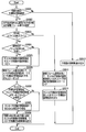
- Steps S2301 to S2303 and S2306 in FIG. 23 are the same processes as steps S2201 to S2203 and S2204 shown in FIG. 22, respectively. A description of these steps is omitted.
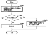
- the difference from the flowchart of FIG. 22 is that a second condition determination (step S2304) and a second response (step S2305) are added after the first response shown in S2303.
- a second condition determination step S2304
- a second response step S2305
- the condition (B) is used for the first condition and the second condition
- the correspondence (2) is used for the first correspondence
- the correspondence (1) is used for the second correspondence.
- Correspondence (2) obtains motion information from spatially different block positions. For this reason, when the motion information does not change spatially, the motion information is the same before and after the first correspondence. As described above, when the motion information is the same before and after the first correspondence, the prediction direction is set to unidirectional prediction by applying the second correspondence (step S2305), thereby reducing the amount of motion compensation processing. . Therefore, this embodiment can improve the prediction efficiency of bidirectional prediction and reduce the amount of motion compensation processing when the motion information does not change spatially. As a result, encoding efficiency can be improved.
- H. A case where the weighted prediction shown in H.264 is applied will be described by taking the process of the predicted motion information setting unit 1002 shown in FIG. 22 as an example.
- FIGS. 23A and 23B illustrate the configuration of a reference frame when weighted prediction is applied.
- t indicates the time of the encoding target frame
- reference frame positions t-1 and t-2 indicate that the reference frame is one frame and two frames in the past with respect to the encoding target frame, respectively. Indicates that it is located.
- the number of reference frames is 4, and a reference frame number is assigned to each reference frame.
- the reference frames with reference frame numbers 0 and 1 are both reference frames at the position t ⁇ 1, but the presence / absence (on / off) of weighted prediction is different.
- the reference frames with reference frame numbers 0 and 1 are not treated as the same reference frame. That is, the reference frames having the reference frame numbers 0 and 1 are regarded as different reference frames even if the reference frames are at the same position if the presence or absence of weighted prediction is different.
- the predicted motion information setting unit 1002 determines that the first condition is not satisfied.
- FIG. 23B illustrates the configuration of the reference frame when the weighted prediction parameters are different.
- the weighted prediction parameters are a weight coefficient (weight) a and an offset (b) used for weighted prediction, and are held for the luminance and chrominance signals, respectively.
- the luminance signal weight coefficient a0 and the offset b0 are held for the reference frame of reference frame number 0, and the luminance signal weight coefficient a1 and the offset b1 are held for the reference frame of reference frame number 1. .
- reference frame numbers 0, 1 and 2 are not treated as the same reference frame.
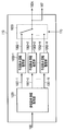
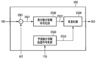
- the motion information encoding unit 503 includes a subtraction unit 2501, a difference motion information encoding unit 2502, a predicted motion information position encoding unit 2503, and a multiplexing unit 2504.
- the subtraction unit 2501 subtracts the predicted motion information 167 from the motion information 160 to generate differential motion information 2551.
- the difference motion information encoding unit 2502 encodes the difference motion information 2551 to generate encoded data 2552. In the skip mode and the merge mode, it is not necessary to encode the differential motion information 2551 in the differential motion information encoding unit 2502.
- the predicted motion information position encoding unit 2503 indicates predicted motion information position information (index Mpvidx shown in FIG. 13A, FIG. 13B, or FIG. 13C) indicating which of the predicted motion information candidates 1051-1 to 1051-Y has been selected. ) Is generated to generate encoded data 2553.
- the predicted motion information position information is included in the encoding control information 170 given from the encoding control unit 120.
- the predicted motion information position information is encoded (equal length encoding or variable length encoding) using a code table generated from the total number of corrected predicted motion information candidates 1052 in the predicted motion information acquisition unit 110.
- the predicted motion information position information may be variable-length encoded using the correlation with the adjacent block.
- a code table is created from the total number of modified predicted motion information candidates 1052 from which the overlapping predicted motion information candidates 1051 are deleted, and predicted motion information is generated according to this code table.
- the position information may be encoded.
- the corrected predicted motion information candidates are determined as the predicted motion information 167 and the motion information candidate 160A, and it is not necessary to encode the predicted motion information position information.
- the multiplexing unit 2504 generates encoded data 553 by multiplexing the encoded data 2552 and the encoded data 2553.
- the derivation method of the corrected predicted motion information candidate 1052 does not have to be the same, and the derivation method of the corrected predicted motion information candidate 1052 may be set independently.
- the method for deriving the corrected predicted motion information candidate 1052 in the skip mode and the merge mode is the same, and the method for deriving the corrected predicted motion information candidate 1052 in the inter mode is different.
- the syntax indicates the structure of encoded data (for example, encoded data 163 in FIG. 1) when the moving image encoding apparatus encodes moving image data.
- the moving picture decoding apparatus interprets the syntax with reference to the same syntax structure.
- FIG. 26 illustrates a syntax 2600 used by the video encoding apparatus 100 in FIG.
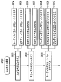
- the syntax 2600 includes three parts: a high level syntax 2601, a slice level syntax 2602, and a coding tree level syntax 2603.
- the high level syntax 2601 includes syntax information of a layer higher than the slice.
- a slice refers to a rectangular area or a continuous area included in a frame or a field.
- the slice level syntax 2602 includes information necessary for decoding each slice.
- Coding tree level syntax 2603 includes information necessary to decode each coding tree (ie, each coding tree unit). Each of these parts includes more detailed syntax.
- the high level syntax 2601 includes sequence and picture level syntax such as sequence parameter set syntax 2604 and picture parameter set syntax 2605.
- the slice level syntax 2602 includes a slice header syntax 2606, a slice data syntax 2607, and the like.
- the coding tree level syntax 2603 includes a coding tree unit syntax 2608, a transform unit syntax 2609, a prediction unit syntax 2610, and the like.
- the coding tree unit syntax 2608 can have a quadtree structure. Specifically, the coding tree unit syntax 2608 can be recursively called as a syntax element of the coding tree unit syntax 2608. That is, one coding tree unit can be subdivided with a quadtree.
- the coding tree unit syntax 2608 includes a transform unit syntax 2609 and a prediction unit syntax 2610. The transform unit syntax 2609 and the prediction unit syntax 2610 are invoked at each coding tree unit syntax 2608 at the extreme end of the quadtree.
- Prediction unit syntax 2610 describes information related to prediction
- transform unit syntax 2609 describes information related to inverse orthogonal transform and quantization.
- FIG. 27 shows an example of the prediction unit syntax.
- the skip_flag shown in FIG. 27 is a flag indicating whether or not the prediction mode of the coding tree unit to which the prediction unit syntax belongs is the skip mode.
- skip_flag is set to 1.
- skip_flag indicates that syntaxes other than the predicted motion information position information 2554 (coding tree unit syntax, prediction unit syntax, transform unit syntax) are not encoded.
- NumMergeCandidates indicates the number of modified prediction motion information candidates 1052 generated using, for example, the list of FIG. 13A.
- merge_idx which is the predicted motion information position information 2554 indicating which block of the modified predicted motion information candidate 1052 is to be merged is encoded. If merge_idx is not encoded, its value is set to zero.
- merge_idx which is predicted motion information position information 2554 indicating which block of the corrected predicted motion information candidates 1052 is to be merged from. Are encoded.
- merge_flag When merge_flag is 1, it is not necessary to encode prediction unit syntax other than merge_flag and merge_idx.
- mvd_lX 0 or 1 indicating the difference motion vector information included in the difference motion information 2551 and the reference frame number ref_idx_lX are encoded.
- inter_pred_idc indicating whether the prediction unit is unidirectional prediction (list 0 or list 1) or bidirectional prediction is encoded.
- NumMVPCand (L0) and NumMVPCand (L1) are acquired.
- NumMVPCand (L0) and NumMVPCand (L1) indicate the number of corrected predicted motion information candidates 1052 in list 0 prediction and list 1 prediction, respectively.
- mvp_idx_lX indicating the predicted motion information position information 2554 is encoded.
- the video encoding apparatus sets the motion information of the encoding target prediction unit using the motion information of the encoded pixel block in order to perform inter prediction.
- the motion compensation processing and the average in the inter prediction are set by setting the prediction direction to unidirectional prediction. Processing can be reduced. As a result, the amount of processing in inter prediction can be reduced, and coding efficiency is improved.
- the moving image decoding apparatus decodes encoded data generated by, for example, the moving image encoding apparatus 100 according to the first embodiment.
- FIG. 28 schematically shows a video decoding device 2800 according to the second embodiment.
- the encoded data 2850 is input to the moving picture decoding apparatus 2800 from, for example, the moving picture encoding apparatus 100 in FIG. 1 through a storage system or a transmission system (not shown).
- the moving picture decoding apparatus 2800 decodes the received encoded data 2850 to generate a decoded picture signal 2854.
- the generated decoded image signal 2854 is temporarily stored in the output buffer 2830 and transmitted as an output image.
- the moving picture decoding apparatus 2800 includes an entropy decoding unit 2801, an inverse quantization unit 2802, an inverse orthogonal transform unit 2803, an addition unit 2804, a reference image memory 2805, an inter prediction.
- the moving picture decoding apparatus 2800 can include an intra prediction unit (not shown).
- the moving picture decoding apparatus 2800 can also be realized by causing a computer to execute an image decoding program.
- the entropy decoding unit 2801 performs decoding based on the syntax in order to decode the encoded data 2850.
- the entropy decoding unit 2801 sequentially entropy-decodes the code string of each syntax, and reproduces encoding parameters related to the decoding target block such as motion information 2859A, prediction information 2860, and quantized transform coefficient 2851.
- the encoding parameter is a parameter necessary for decoding such as prediction information, information on transform coefficients, information on quantization, and the like.
- the entropy decoding unit 2801 includes a separation unit 2901, a parameter decoding unit 2902, a transform coefficient decoding unit 2903, and a motion information decoding unit 2904 as shown in FIG.
- the separation unit 2901 separates the encoded data 2850 into encoded data 2951 relating to parameters, encoded data 2952 relating to transform coefficients, and encoded data 2953 relating to motion information.
- Separating section 2901 provides encoded data 2951 related to parameters to parameter decoding section 2902, encoded data 2952 related to transform coefficients to transform coefficient decoding section 2903, and encoded data 2953 related to motion information to motion information decoding section 2904. Output each.
- the parameter decoding unit 2902 decodes the encoded data 2951 related to the parameters to obtain encoded parameters 2870 such as prediction information 2860.
- the parameter decoding unit 2902 outputs the encoding parameter 2870 to the decoding control unit 2820.
- Prediction information 2860 includes motion information candidate 2859A output from the motion information decoding unit 2904 and prediction motion information acquisition for switching whether to apply inter prediction or intra prediction to a decoding target prediction unit. This is used for switching by the motion information selection switch 2809 which of the motion information candidates 2859B output from the unit 2808 is used.
- the transform coefficient decoding unit 2903 decodes the encoded data 2952 to obtain a quantized transform coefficient 2851.
- the transform coefficient decoding unit 2903 outputs the quantized transform coefficient 2851 to the inverse quantization unit 2802.
- the motion information decoding unit 2904 decodes the encoded data 2953 from the separation unit 2901 and generates predicted motion information position information 2861 and motion information 2859A.
- the motion information decoding unit 2904 includes a separation unit 3001, a differential motion information decoding unit 3002, a predicted motion information position decoding unit 3003, and an addition unit 3004 as shown in FIG.
- the encoded data 2953 related to the motion information is input to the separation unit 3001.
- the separation unit 3001 separates the encoded data 2953 into encoded data 3051 related to differential motion information and encoded data 3052 related to a predicted motion information position.
- the differential motion information decoding unit 3002 decodes the encoded data 3051 related to the differential motion information to obtain differential motion information 3053. In the skip mode and the merge mode, the differential motion information encoding unit 3002 does not need to decode the differential motion information 3053.
- the addition unit 3004 adds the difference motion information 3053 to the predicted motion information 2862 from the predicted motion information acquisition unit 2808 to generate motion information 2859A.
- the motion information 2859A is sent to the motion information selection switch 2809.
- the predicted motion information position decoding unit 3003 decodes the encoded data 3052 related to the predicted motion information position to obtain predicted motion information position information 2861.
- the predicted motion information position information 2861 is sent to the predicted motion information acquisition unit 2808.
- the predicted motion information position information 2861 is decoded (equal length decoding or variable length decoding) using a code table generated from the total number of modified predicted motion information candidates 3052.
- the predicted motion information position information 2861 may be variable-length decoded using the correlation with the adjacent block. Further, when a plurality of corrected predicted motion information candidates 1052 overlap, the predicted motion information position information 2861 may be decoded according to a decoding table generated from the total number of corrected predicted motion information candidates 1052 from which the duplication is deleted. Further, when the total number of the corrected predicted motion information candidates 1052 is one type, the corrected predicted motion information candidate 1052 is determined as the predicted motion information candidate 2859B, and thus it is not necessary to decode the predicted motion information position information 2861.
- the inverse quantization unit 2802 shown in FIG. 28 inversely quantizes the quantized transform coefficient 2851 from the entropy decoding unit 2801 to obtain a restored transform coefficient 2852. Specifically, the inverse quantization unit 2802 performs inverse quantization processing according to the quantization information obtained by the entropy decoding unit 2801. The inverse quantization unit 2802 outputs the restored transform coefficient 2852 to the inverse orthogonal transform unit 2803.
- the inverse orthogonal transform unit 2803 performs an inverse orthogonal transform corresponding to the orthogonal transform performed on the encoding side on the reconstruction transform coefficient 2852 from the inverse quantization unit 2802, and obtains a reconstruction prediction error signal 2853.
- the orthogonal transform in the orthogonal transform unit 102 of FIG. 1 is DCT
- the inverse orthogonal transform unit 2803 performs IDCT.
- the inverse orthogonal transform unit 2803 outputs the restored prediction error signal 2853 to the addition unit 2804.
- the addition unit 2804 adds the restored prediction error signal 2853 and the corresponding predicted image signal 2856 to generate a decoded image signal 2854.
- the decoded image signal 2854 is temporarily stored in the output buffer 2830 as an output image signal after filtering processing.
- the decoded image signal 2854 stored in the output buffer 2830 is output according to the output timing managed by the decoding control unit 2820. For example, a deblocking filter or a Wiener filter is used for filtering the decoded image signal 2854.
- the decoded image signal 2854 after the filtering process is also stored in the reference image memory 2805 as a reference image signal 2855.
- the reference image signal 2855 stored in the reference image memory 2805 is referred to by the inter prediction unit 2806 in units of frames or fields as necessary.
- the inter prediction unit 2806 performs inter prediction using the reference image signal 2855 stored in the reference image memory 2805. Specifically, the inter prediction unit 2806 receives motion information 2859 including a motion shift amount (motion vector) between the prediction target block and the reference image signal 2855 from the motion information selection switch 2809, and based on this motion vector. Then, an inter prediction image is generated by performing interpolation processing (motion compensation). Since the generation of the inter prediction image is the same as that of the first embodiment, detailed description thereof is omitted.
- the motion information memory 2807 temporarily stores the motion information 2859 used for inter prediction in the inter prediction unit 2806 as reference motion information 2858. Since the motion information memory 2807 has the same function as that of the motion information memory 109 shown in the first embodiment, a duplicate description will be omitted as appropriate.
- the reference motion information 2858 is held in units of frames (or slices). Specifically, the motion information memory 2807 stores the motion information 2859 of the decoding target frame as the reference motion information 2858, and the motion information 2859 of the already decoded frame as the reference motion information 2858. And a time direction reference motion information memory to be stored. As many temporal direction reference motion information memories as the number of reference frames used for prediction of a decoding target frame can be prepared.
- the reference motion information 2858 is held in a spatial direction reference motion information memory and a temporal direction reference motion information memory in a predetermined area unit (for example, 4 ⁇ 4 pixel block unit).
- the reference motion information 2858 further includes information indicating whether inter prediction or intra prediction is applied to the region.
- the predicted motion information acquisition unit 2808 refers to the reference motion information 2858 stored in the motion information memory 2807, and the motion information candidate 2859B used for the decoding target prediction unit and the motion information difference in the entropy decoding unit 2801 Predictive motion information 2862 used for encoding is generated.
- the decoding control unit 2820 controls each element of the video decoding device 2800 in FIG. Specifically, the decoding control unit 2820 receives information including the encoding parameter 2870 from the entropy decoding unit 2801 from the video decoding device 2800, and gives the decoding control information 2871 to the video decoding device 2800. Thus, various controls for the decoding process are performed.
- the moving picture decoding apparatus 2800 uses a plurality of prediction modes with different decoding processes, similarly to the encoding process described with reference to FIG.
- the skip mode is a mode in which only the syntax related to the predicted motion information position information 2861 is decoded and no other syntax is decoded.
- the merge mode is a mode in which the syntax related to the predicted motion information position information 2861 and the information related to the transform coefficient are decoded and the other syntaxes are not decoded.
- the inter mode is a mode for decoding syntax related to the predicted motion information position information 2861, differential motion information, and information related to transform coefficients. These modes are switched according to prediction information controlled by the decoding control unit 2820.
- FIG. 31 shows the predicted motion information acquisition unit 2808 in more detail.
- the predicted motion information acquisition unit 2808 has the same configuration as the predicted motion information acquisition unit 110 of the video encoding device as illustrated in FIG. 10, and thus detailed description of the predicted motion information acquisition unit 2808 is omitted.
- W represents the number of predicted motion information candidates generated by the reference motion information acquisition unit 3101.
- the reference motion information acquisition unit 3101 acquires reference motion information 2858 from the motion information memory 2807.
- the reference motion information acquisition unit 3101 generates one or more predicted motion information candidates 3151-1, 3151-2,..., 3151-W using the acquired reference motion information 2858.
- the predicted motion information candidate is also referred to as a predicted motion vector candidate.
- the prediction motion information setting units 3102-1 to 3102-W receive the prediction motion information candidates 3151-1 to 3151 -W from the reference motion information acquisition unit 3101, respectively, and apply the prediction method (one-way) to the decoding target prediction unit. Prediction, bi-directional prediction) and reference frame number setting, and scaling of motion vector information are performed to generate modified prediction motion information candidates 3152-1 to 3152-W, respectively.
- the predicted motion information selection switch 3103 selects any one of one or more modified predicted motion information candidates 3152-1 to 3152-W according to a command included in the encoding control information 2871 from the decoding control unit 2820.
- the predicted motion information selection switch 3103 outputs the selected motion information candidate 2859B to the motion information selection switch 2809, and also outputs predicted motion information 2862 used for differential decoding of motion information in the entropy decoding unit 2801. .
- the motion information candidate 2859B and the predicted motion information 2862 include the same motion information, but may include different motion information in accordance with an instruction from the decoding control unit 2820.
- the predicted motion information selection switch 3103 may output the predicted motion information position information instead of the decoding control unit 2820.
- the decoding control unit 2820 determines which one of the corrected predicted motion information candidates 3152-1 to 3152-W is to be selected by using an evaluation function such as the above formula (1) or formula (2).
- the list 0 predicted motion information candidate held by motion information candidate 2859B is the list 1 predicted motion information candidate. May be copied.
- the reference motion information 2858 including the list 0 predicted motion information and the list 1 predicted motion information which is the same information as the list 0 predicted motion information is stored in the adjacent prediction unit when decoding the subsequent prediction unit. Used as the reference motion information 2858 by the predicted motion information acquisition unit 2808.
- each of the predicted motion information setting units 3102-1 to 3102-W, the predicted motion information candidates 3151-1 to 3151-W, and the modified predicted motion information candidates 3152-1 to 3152-W will be described without particular distinction.
- the numbers at the end of the reference signs (“ ⁇ 1” to “ ⁇ W”) are omitted, and are simply described as the predicted motion information setting unit 3102, the predicted motion information candidate 3151, and the corrected predicted motion information candidate 3152.
- the predicted motion information setting unit 3102 generates, for example, one or more predicted motion information candidates 3151 in the same manner as the predicted motion information candidate 1001 of the video encoding device 100 illustrated in FIG.
- the method for generating the predicted motion information candidate 3151 is the same as that described with reference to FIGS. 11A to 17F with respect to the video encoding device, and thus detailed description thereof is omitted.
- the reference motion information acquisition unit 3101 generates the predicted motion information candidate 3151 according to the list of FIG. 13A.
- two prediction motion information candidates 3151-1 and 3151-2 are generated with reference to a prediction unit spatially adjacent to the decoding target prediction unit, and the decoding target prediction unit
- One motion information candidate 3151-3 is generated with reference to a prediction unit that is temporally adjacent to.
- the position of the adjacent prediction unit having the smallest value of X among the adjacent prediction units is determined as the block position A.
- the predicted motion information candidate 3151-1 with the index Mvpidx of 0 is generated from the reference motion information of the adjacent prediction unit at the block position A located in the spatial direction.
- the position of the adjacent prediction unit having the smallest Y value among the determined adjacent prediction units is determined as the block position B.
- the predicted motion vector candidate 3151-2 with the index Mvpidx of 1 is generated from the reference motion information of the adjacent prediction unit at the block position B located in the spatial direction.
- predicted motion vector candidate 3151-3 with the index Mvpidx of 2 is generated from the reference motion information of the adjacent prediction unit at the position Col in the reference frame.
- the reference motion information acquisition unit (also referred to as a predicted motion information candidate generation unit) 3101 refers to the motion information memory 2807 and generates one or more predicted motion information candidates 3151-1 to 3151 -W. .
- the prediction unit referred to for generation of the predicted motion information candidate 3151 that is, the prediction unit from which the predicted motion information candidate is acquired or output is referred to as a reference motion block.
- the predicted motion information candidate 3151 is a list 0 predicted motion information candidate used for list 0 prediction and a list 1 predicted motion information candidate used for list 1 prediction.
- the predicted motion information candidate 3151 includes both the list 0 predicted motion information candidate and the list 1 predicted motion information candidate.
- FIG. 32 shows an example of processing of the predicted motion information setting unit 3102.
- a prediction motion information setting unit 3102 illustrated in FIG. 32 has the same function as the prediction motion information setting unit 1002 of the video encoding device 100 illustrated in FIG.
- the processing procedure of FIG. 32 can be understood by replacing “encoding” with “decoding” in the description of the processing procedure of FIG. 18, and thus detailed description thereof will be omitted as appropriate.
- the predicted motion information setting unit 3102 has the predicted motion information candidate 3151 output from the spatial reference motion block or the temporal motion reference motion block. Is determined (step S3201).
- the predicted motion information setting unit 3102 outputs the predicted motion information candidate 3151 as the corrected predicted motion information candidate 3152. (Step S3212).
- the prediction motion information setting unit 3102 applies the prediction direction and reference frame to be applied to the decoding target prediction unit.
- a number is set (step S3202). Specifically, when the decoding target prediction unit is a pixel block in a P slice to which only unidirectional prediction is applied, the prediction direction is set to unidirectional prediction. Furthermore, when the decoding target prediction unit is a pixel block in a B slice to which unidirectional prediction and bidirectional prediction can be applied, the prediction direction is set to bidirectional prediction.
- the reference frame number is set with reference to a decoded prediction unit located in the spatial direction. For example, the reference frame number is determined by majority using the reference frame number of the prediction unit at a predetermined position adjacent to the decoding target prediction unit.
- the prediction motion information setting unit 3102 determines whether or not the slice to which the decoding target prediction unit belongs (also referred to as a decoding slice) is a B slice (step S3203).
- the decoded slice is a P slice (NO in step S3203)
- the motion motion information candidate 3151 includes one of a list 0 predicted motion information candidate and a list 1 predicted motion information candidate.
- the predicted motion information setting unit 3102 scales the motion vector included in the list 0 predicted motion information candidate or the list 1 predicted motion information candidate using the reference frame number set in step S3202 (step S3210). Further, the predicted motion information setting unit 3102 outputs the list 0 predicted motion information candidate or the list 1 predicted motion information candidate including the scaled motion vector as the modified predicted motion information candidate 3152 (step S3211).
- the motion estimation information setting unit 3102 determines whether or not the unidirectional prediction is applied to the reference motion block (step S3204).
- the unidirectional prediction is applied to the reference motion block (the determination in step S3204 is YES)
- the predicted motion information setting unit 3102 displays the list 0.
- the predicted motion information candidate is copied to the list 1 predicted motion information candidate (step S3205). If bi-directional prediction is applied to the reference motion block (the determination in step S3204 is NO), the process skips step S3205 and proceeds to step S3206.
- the predicted motion information setting unit 3102 scales the motion vector of the list 0 predicted motion information candidate and the motion vector of the list 1 predicted motion information candidate using the reference frame number set in step S3202 (step S3206). ). Next, the predicted motion information setting unit 3102 determines whether the block referred to by the list 0 predicted motion information candidate and the block referred to by the list 1 predicted motion information candidate are the same (step S3207).
- the predicted motion information setting unit 3102 changes the prediction direction from bidirectional prediction to unidirectional prediction, and outputs a corrected predicted motion information candidate 3152 including only the list 0 predicted motion information candidate (step S3208).
- the prediction direction is changed from bidirectional prediction to unidirectional prediction. Motion compensation processing and average processing in prediction can be reduced.
- the predicted motion information setting unit 3102 performs bidirectional prediction on the prediction direction. And the corrected predicted motion information candidate 3152 including the list 0 predicted motion information candidate and the list 1 predicted motion information candidate is output (step S3209).
- the motion information of the decoding target prediction unit is set using the motion information of the decoded pixel block, and the list 0 prediction is performed.
- the motion compensation processing and the average processing in the inter prediction are reduced by setting the prediction direction to unidirectional prediction. be able to. As a result, the processing amount in inter prediction can be reduced.
- steps S3301 to S3306 and S3310 to S3312 in FIG. 33 are the same as steps S3201 to 3206 and S3210 to S3212 shown in FIG.
- step S3307 the predicted motion information setting unit 3102 determines whether the block referred to by the list 0 predicted motion information candidate generated in steps S3301 to S3306 is the same as the block referred to by the list 1 predicted motion information candidate. To do.
- a predicted value (predicted image) generated by bidirectional prediction Is equivalent to a predicted value (predicted image) generated by unidirectional prediction.
- the predicted motion information setting unit 1002 derives the list 1 predicted motion information candidate again from a position spatially different from the reference motion information acquisition position from which the list 1 predicted motion information candidate is derived (step S3308).
- the reference motion information acquisition position used at the start of the process shown in FIG. 33 is referred to as a first reference motion information acquisition position
- the first reference motion information acquisition position is set to a position circumscribing to the lower right of the prediction unit at the position Col in the reference frame, as indicated by a circle in FIG. 17A.
- the information acquisition position is set to a predetermined position in the prediction unit at the position Col of the same reference frame, as indicated by a circle in FIG. 14A.
- the first reference motion information acquisition position and the second reference motion information acquisition position may be located in reference frames that are temporally different from each other, or may be set to positions that are different in time and space.
- the motion information of the decoding target prediction unit is set using the motion information of the decoded pixel block, and the list 0 prediction is performed. If the block referenced by the motion information in the list and the block referenced by the motion information in the list 1 prediction are the same, the motion information in the list 1 prediction is acquired by a method different from the method for acquiring the motion information in the list 0 prediction. In addition, bidirectional prediction having higher prediction efficiency than unidirectional prediction can be realized. In addition, since the motion information acquisition position in the list 1 prediction is set to a position close to the position of the conventional acquisition position, two types of motion information suitable for bidirectional prediction can be acquired. Further, the prediction efficiency is improved.
- the predicted motion information setting unit 3102 acquires two types of motion information (first predicted motion information and second predicted motion information) from the decoded region (step S3401). For example, two types of motion information can be acquired from the reference motion information acquisition position described above.
- the frequency of motion information adapted to the decoding target prediction unit may be calculated so far, and high-frequency motion information may be used. Motion information may be used.
- the predicted motion information setting unit 3102 determines whether or not the two types of motion information acquired in step S3401 satisfy the first condition (step S3402).
- the first condition includes at least one of the following conditions (A) to (F).
- (D) The motion vectors included in the two types of motion information are the same.
- E The absolute value of the difference between the motion vectors included in the two types of motion information is less than or equal to a predetermined threshold.
- step S3402 in which the number and configuration of reference frames used for 0 prediction and list 1 prediction are the same, two or more types of motion information are the first when the conditions (A) to (F) are satisfied. It is determined that the condition is satisfied. Further, it may be determined that the first condition is always satisfied.
- a first condition that is the same as the first condition set in the moving picture decoding apparatus 100 described in the first embodiment is set in the moving picture decoding apparatus 2800.
- the video decoding device 2800 may receive information on the first condition from the video encoding device 100 as additional information.
- step S3402 If the first condition is not satisfied (determination in step S3402 is NO), bi-prediction is applied to the decoding target prediction unit without changing the two types of motion information (step S3404). If the first condition is satisfied (YES in step S3402), the motion vector predictor setting unit 3102 performs the first response (step S3403).
- the first correspondence includes one or more of the following correspondences (1) to (6). (1) The prediction method is set to unidirectional prediction, and one of the two types of motion information is output as a list 0 predicted motion information candidate.
- the prediction method is set to bidirectional prediction, and the motion information acquisition position To obtain motion information from spatially different block positions and output two types of motion information as list 0 predicted motion information candidates and list 1 predicted motion information candidates (3)
- Set the prediction method to bidirectional prediction The motion information is acquired from a block position that is temporally different from the acquisition position of the motion information, and two types of motion information are output as a list 0 predicted motion information candidate and a list 1 predicted motion information candidate.
- Bidirectional prediction is set, the reference frame number included in the motion information is changed, and two types of motion information are output as a list 0 predicted motion information candidate and a list 1 predicted motion information candidate.
- the measurement method is set to bidirectional prediction, the motion vector included in the motion information is changed, and two types of motion information are output as a list 0 predicted motion information candidate and a list 1 predicted motion information candidate (2) to ( 5) may be applied only to one of the two types of motion information, or may be applied to both pieces of motion information. Also, typically, in the correspondence (4), the reference frame closest to the decoding target frame is applied instead of the reference frame from which the original motion information was acquired. Typically, correspondence (5) applies a motion vector obtained by shifting the motion vector by a fixed value.
- Steps S3501 to S3503 and S3506 in FIG. 35 are the same processes as steps S3401 to S3403 and S3404 shown in FIG. 34, respectively, and thus the description of these steps is omitted.
- the difference from the processing procedure of FIG. 34 is that a second condition determination (step S3504) and a second response (step S3505) are added after the first response shown in S3503.
- a second condition determination step S3504
- a second response step S3505
- the condition (B) is used for the first condition and the second condition
- the correspondence (2) is used for the first correspondence
- the correspondence (1) is used for the second correspondence.
- Correspondence (2) obtains motion information from spatially different block positions. For this reason, when the motion information does not change spatially, the motion information is the same before and after the first correspondence. Thus, when the motion information is the same before and after the first correspondence, the prediction direction is set to unidirectional prediction by applying the second correspondence (step S3505), thereby reducing the amount of motion compensation processing. . Therefore, this embodiment can improve the prediction efficiency of bidirectional prediction and reduce the amount of motion compensation processing when the motion information does not change spatially.
- the weighted prediction (Weighted Prediction) shown in H.264 may be applied.
- the reference frames with reference frame numbers 0 and 1 are both reference frames at position t ⁇ 1.
- reference frame numbers 0 and One reference frame is not treated as the same reference frame. That is, the reference frames having the reference frame numbers 0 and 1 are regarded as different reference frames even if the reference frames are at the same position if the presence or absence of weighted prediction is different.
- the predicted motion information setting unit 3102 determines that the first condition is not satisfied.
- the luminance signal weight coefficient a0 and the offset b0 are held for the reference frame of reference frame number 0, and the luminance signal weight coefficient a1 and the offset of the reference frame of reference frame number 1 are stored.
- the reference frame numbers 0, 1 and 2 are not treated as the same reference frame.
- the moving picture decoding apparatus 2800 in FIG. 28 can use the same or similar syntax as that described with reference to FIG.
- the video decoding apparatus sets the motion information of the decoding target prediction unit using the motion information of the decoded pixel block in order to perform inter prediction.
- the motion compensation processing and the average in the inter prediction are set by setting the prediction direction to unidirectional prediction. Processing can be reduced. As a result, the amount of processing in inter prediction can be reduced, and decoding efficiency is improved.
- each frame constituting the input image signal is divided into rectangular blocks of 16 ⁇ 16 pixel size and the like, as shown in FIG. 2, from the upper left block to the lower right side of the screen.
- An example in which encoding / decoding is performed in order will be described.
- the encoding order and the decoding order are not limited to this example.
- encoding and decoding may be performed sequentially from the lower right to the upper left, or encoding and decoding may be performed so as to draw a spiral from the center of the screen toward the screen end.
- encoding and decoding may be performed in order from the upper right to the lower left, or encoding and decoding may be performed so as to draw a spiral from the screen edge toward the center of the screen.
- the size of the prediction target block (prediction unit) may be a 16 ⁇ 8 pixel block, an 8 ⁇ 16 pixel block, an 8 ⁇ 4 pixel block, a 4 ⁇ 8 pixel block, or the like. Also, it is not necessary to unify all the block sizes within one coding tree unit, and a plurality of different block sizes may be mixed.
- the amount of codes for encoding or decoding the division information increases as the number of divisions increases. Therefore, it is desirable to select the block size in consideration of the balance between the code amount of the division information and the quality of the locally decoded image or the decoded image.
- the color signal component is described without distinguishing between the luminance signal and the color difference signal.
- the same or different prediction methods may be used.
- the prediction method selected for the chrominance signal can be encoded or decoded in the same manner as the luminance signal.
- syntax elements not defined in the embodiment can be inserted between the rows of the table shown in the syntax configuration, and other conditional branch descriptions are included. It does not matter.
- the syntax table can be divided and integrated into a plurality of tables. Moreover, it is not always necessary to use the same term, and it may be arbitrarily changed depending on the form to be used.
- the instructions shown in the processing procedure shown in the above embodiment can be executed based on a program that is software.
- a general-purpose computer system stores this program in advance, and by reading this program, it is also possible to obtain the same effects as those obtained by the video encoding device and video decoding device of the above-described embodiment. is there.
- the instructions described in the above-described embodiments are, as programs that can be executed by a computer, magnetic disks (flexible disks, hard disks, etc.), optical disks (CD-ROM, CD-R, CD-RW, DVD-ROM, DVD). ⁇ R, DVD ⁇ RW, etc.), semiconductor memory, or a similar recording medium. As long as the recording medium is readable by the computer or the embedded system, the storage format may be any form.
- the computer reads the program from the recording medium and causes the CPU to execute instructions described in the program based on the program
- the computer is similar to the video encoding device and video decoding device of the above-described embodiment. Operation can be realized.
- the computer acquires or reads the program, it may be acquired or read through a network.
- the OS operating system
- database management software database management software
- MW middleware
- a part of each process for performing may be executed.
- the recording medium in the present embodiment is not limited to a medium independent of a computer or an embedded system, but also includes a recording medium in which a program transmitted via a LAN, the Internet, or the like is downloaded and stored or temporarily stored.
- the program for realizing the processing of each of the above embodiments may be stored on a computer (server) connected to a network such as the Internet and downloaded to the computer (client) via the network.
- the number of recording media is not limited to one, and when the processing in this embodiment is executed from a plurality of media, it is included in the recording medium in this embodiment, and the configuration of the media may be any configuration.
- the computer or the embedded system in the present embodiment is for executing each process in the present embodiment based on a program stored in a recording medium.
- the computer or the embedded system includes a single device such as a personal computer or a microcomputer.
- the system may be any configuration such as a system connected to the network.
- the computer in this embodiment is not limited to a personal computer, but includes an arithmetic processing device, a microcomputer, and the like included in an information processing device. ing.
Landscapes
- Engineering & Computer Science (AREA)
- Multimedia (AREA)
- Signal Processing (AREA)
- Compression Or Coding Systems Of Tv Signals (AREA)
Abstract
Un procédé de codage vidéo selon un mode de réalisation de l'invention consiste à : acquérir des premières informations de mouvement prédites et des deuxièmes informations de mouvement prédites à partir d'une région codée comprenant une pluralité de blocs dotés d'informations de mouvement ; et, lorsqu'une première condition est satisfaite, générer une image prédite d'un bloc en cours de codage, le bloc étant généré par utilisation soit (1) des premières informations de mouvement prédites et de troisièmes informations de mouvement prédites, les troisièmes informations de mouvement prédites étant différentes des premières informations de mouvement prédites et des deuxièmes informations de mouvement prédites, et étant acquises à partir de la région codée, soit (2) des premières informations de mouvement prédites et des deuxièmes informations de mouvement prédites. La première condition est que les blocs référencés par les premières informations de mouvement prédites et les deuxièmes informations de mouvement prédites soient les mêmes.
Priority Applications (2)
| Application Number | Priority Date | Filing Date | Title |
|---|---|---|---|
| PCT/JP2011/063738 WO2012172668A1 (fr) | 2011-06-15 | 2011-06-15 | Procédé et dispositif de codage vidéo, et procédé et dispositif de décodage vidéo |
| US14/106,044 US20140105295A1 (en) | 2011-06-15 | 2013-12-13 | Moving image encoding method and apparatus, and moving image decoding method and apparatus |
Applications Claiming Priority (1)
| Application Number | Priority Date | Filing Date | Title |
|---|---|---|---|
| PCT/JP2011/063738 WO2012172668A1 (fr) | 2011-06-15 | 2011-06-15 | Procédé et dispositif de codage vidéo, et procédé et dispositif de décodage vidéo |
Related Child Applications (1)
| Application Number | Title | Priority Date | Filing Date |
|---|---|---|---|
| US14/106,044 Continuation US20140105295A1 (en) | 2011-06-15 | 2013-12-13 | Moving image encoding method and apparatus, and moving image decoding method and apparatus |
Publications (1)
| Publication Number | Publication Date |
|---|---|
| WO2012172668A1 true WO2012172668A1 (fr) | 2012-12-20 |
Family
ID=47356694
Family Applications (1)
| Application Number | Title | Priority Date | Filing Date |
|---|---|---|---|
| PCT/JP2011/063738 Ceased WO2012172668A1 (fr) | 2011-06-15 | 2011-06-15 | Procédé et dispositif de codage vidéo, et procédé et dispositif de décodage vidéo |
Country Status (2)
| Country | Link |
|---|---|
| US (1) | US20140105295A1 (fr) |
| WO (1) | WO2012172668A1 (fr) |
Cited By (15)
| Publication number | Priority date | Publication date | Assignee | Title |
|---|---|---|---|---|
| US20210297659A1 (en) | 2018-09-12 | 2021-09-23 | Beijing Bytedance Network Technology Co., Ltd. | Conditions for starting checking hmvp candidates depend on total number minus k |
| JP2021530183A (ja) * | 2018-06-29 | 2021-11-04 | 北京字節跳動網絡技術有限公司Beijing Bytedance Network Technology Co., Ltd. | Lutにおける動き候補のチェック順序 |
| US11463685B2 (en) | 2018-07-02 | 2022-10-04 | Beijing Bytedance Network Technology Co., Ltd. | LUTS with intra prediction modes and intra mode prediction from non-adjacent blocks |
| US11528501B2 (en) | 2018-06-29 | 2022-12-13 | Beijing Bytedance Network Technology Co., Ltd. | Interaction between LUT and AMVP |
| US11528500B2 (en) | 2018-06-29 | 2022-12-13 | Beijing Bytedance Network Technology Co., Ltd. | Partial/full pruning when adding a HMVP candidate to merge/AMVP |
| US11589071B2 (en) | 2019-01-10 | 2023-02-21 | Beijing Bytedance Network Technology Co., Ltd. | Invoke of LUT updating |
| US11641483B2 (en) | 2019-03-22 | 2023-05-02 | Beijing Bytedance Network Technology Co., Ltd. | Interaction between merge list construction and other tools |
| JP2023089173A (ja) * | 2020-12-18 | 2023-06-27 | 株式会社Jvcケンウッド | 画像符号化装置、画像符号化方法及び画像符号化プログラム、並びに画像復号化装置、画像復号化方法及び画像復号化プログラム |
| US11695921B2 (en) | 2018-06-29 | 2023-07-04 | Beijing Bytedance Network Technology Co., Ltd | Selection of coded motion information for LUT updating |
| US11877002B2 (en) | 2018-06-29 | 2024-01-16 | Beijing Bytedance Network Technology Co., Ltd | Update of look up table: FIFO, constrained FIFO |
| US11895318B2 (en) | 2018-06-29 | 2024-02-06 | Beijing Bytedance Network Technology Co., Ltd | Concept of using one or multiple look up tables to store motion information of previously coded in order and use them to code following blocks |
| US11909951B2 (en) | 2019-01-13 | 2024-02-20 | Beijing Bytedance Network Technology Co., Ltd | Interaction between lut and shared merge list |
| US11909989B2 (en) | 2018-06-29 | 2024-02-20 | Beijing Bytedance Network Technology Co., Ltd | Number of motion candidates in a look up table to be checked according to mode |
| US11956464B2 (en) | 2019-01-16 | 2024-04-09 | Beijing Bytedance Network Technology Co., Ltd | Inserting order of motion candidates in LUT |
| US11973971B2 (en) | 2018-06-29 | 2024-04-30 | Beijing Bytedance Network Technology Co., Ltd | Conditions for updating LUTs |
Families Citing this family (2)
| Publication number | Priority date | Publication date | Assignee | Title |
|---|---|---|---|---|
| US9544592B2 (en) * | 2012-02-10 | 2017-01-10 | Texas Instruments Incorporated | Methods and systems for encoding pictures associated with video data |
| KR101756759B1 (ko) * | 2016-01-07 | 2017-07-12 | 주식회사 마크애니 | 화질 손상을 방지하는 동영상 스트림에 대한 부가 데이터 삽입 방법 및 장치 |
Citations (4)
| Publication number | Priority date | Publication date | Assignee | Title |
|---|---|---|---|---|
| JP2004007379A (ja) * | 2002-04-10 | 2004-01-08 | Toshiba Corp | 動画像符号化方法及び動画像復号化方法 |
| JP2004056756A (ja) * | 2002-07-18 | 2004-02-19 | Lg Electronics Inc | 予測動きベクトル演算方法 |
| JP2008541502A (ja) * | 2005-05-26 | 2008-11-20 | 株式会社エヌ・ティ・ティ・ドコモ | 動き及び予測の重み付けパラメータを符号化する方法及び装置 |
| JP2010010950A (ja) * | 2008-06-25 | 2010-01-14 | Toshiba Corp | 画像符号化/復号化方法及び装置 |
Family Cites Families (2)
| Publication number | Priority date | Publication date | Assignee | Title |
|---|---|---|---|---|
| US9288501B2 (en) * | 2011-03-08 | 2016-03-15 | Qualcomm Incorporated | Motion vector predictors (MVPs) for bi-predictive inter mode in video coding |
| US8934552B2 (en) * | 2011-03-31 | 2015-01-13 | Qualcomm Incorporated | Combined reference picture list construction and mapping |
-
2011
- 2011-06-15 WO PCT/JP2011/063738 patent/WO2012172668A1/fr not_active Ceased
-
2013
- 2013-12-13 US US14/106,044 patent/US20140105295A1/en not_active Abandoned
Patent Citations (4)
| Publication number | Priority date | Publication date | Assignee | Title |
|---|---|---|---|---|
| JP2004007379A (ja) * | 2002-04-10 | 2004-01-08 | Toshiba Corp | 動画像符号化方法及び動画像復号化方法 |
| JP2004056756A (ja) * | 2002-07-18 | 2004-02-19 | Lg Electronics Inc | 予測動きベクトル演算方法 |
| JP2008541502A (ja) * | 2005-05-26 | 2008-11-20 | 株式会社エヌ・ティ・ティ・ドコモ | 動き及び予測の重み付けパラメータを符号化する方法及び装置 |
| JP2010010950A (ja) * | 2008-06-25 | 2010-01-14 | Toshiba Corp | 画像符号化/復号化方法及び装置 |
Cited By (30)
| Publication number | Priority date | Publication date | Assignee | Title |
|---|---|---|---|---|
| US12058364B2 (en) | 2018-06-29 | 2024-08-06 | Beijing Bytedance Network Technology Co., Ltd. | Concept of using one or multiple look up tables to store motion information of previously coded in order and use them to code following blocks |
| US12034914B2 (en) | 2018-06-29 | 2024-07-09 | Beijing Bytedance Network Technology Co., Ltd | Checking order of motion candidates in lut |
| US12556738B2 (en) | 2018-06-29 | 2026-02-17 | Beijing Bytedance Network Technology Co., Ltd. | Update of look up table: FIFO, constrained FIFO |
| US11528501B2 (en) | 2018-06-29 | 2022-12-13 | Beijing Bytedance Network Technology Co., Ltd. | Interaction between LUT and AMVP |
| US11528500B2 (en) | 2018-06-29 | 2022-12-13 | Beijing Bytedance Network Technology Co., Ltd. | Partial/full pruning when adding a HMVP candidate to merge/AMVP |
| US12549756B2 (en) | 2018-06-29 | 2026-02-10 | Beijing Bytedance Network Technology Co., Ltd. | Partial/full pruning when adding a HMVP candidate to merge/AMVP |
| US12167018B2 (en) | 2018-06-29 | 2024-12-10 | Beijing Bytedance Network Technology Co., Ltd. | Interaction between LUT and AMVP |
| US11973971B2 (en) | 2018-06-29 | 2024-04-30 | Beijing Bytedance Network Technology Co., Ltd | Conditions for updating LUTs |
| US11695921B2 (en) | 2018-06-29 | 2023-07-04 | Beijing Bytedance Network Technology Co., Ltd | Selection of coded motion information for LUT updating |
| US11706406B2 (en) | 2018-06-29 | 2023-07-18 | Beijing Bytedance Network Technology Co., Ltd | Selection of coded motion information for LUT updating |
| JP7328330B2 (ja) | 2018-06-29 | 2023-08-16 | 北京字節跳動網絡技術有限公司 | Lutにおける動き候補のチェック順序 |
| US11877002B2 (en) | 2018-06-29 | 2024-01-16 | Beijing Bytedance Network Technology Co., Ltd | Update of look up table: FIFO, constrained FIFO |
| US11895318B2 (en) | 2018-06-29 | 2024-02-06 | Beijing Bytedance Network Technology Co., Ltd | Concept of using one or multiple look up tables to store motion information of previously coded in order and use them to code following blocks |
| US11909989B2 (en) | 2018-06-29 | 2024-02-20 | Beijing Bytedance Network Technology Co., Ltd | Number of motion candidates in a look up table to be checked according to mode |
| JP2021530183A (ja) * | 2018-06-29 | 2021-11-04 | 北京字節跳動網絡技術有限公司Beijing Bytedance Network Technology Co., Ltd. | Lutにおける動き候補のチェック順序 |
| US11463685B2 (en) | 2018-07-02 | 2022-10-04 | Beijing Bytedance Network Technology Co., Ltd. | LUTS with intra prediction modes and intra mode prediction from non-adjacent blocks |
| US11997253B2 (en) | 2018-09-12 | 2024-05-28 | Beijing Bytedance Network Technology Co., Ltd | Conditions for starting checking HMVP candidates depend on total number minus K |
| US20210297659A1 (en) | 2018-09-12 | 2021-09-23 | Beijing Bytedance Network Technology Co., Ltd. | Conditions for starting checking hmvp candidates depend on total number minus k |
| US11589071B2 (en) | 2019-01-10 | 2023-02-21 | Beijing Bytedance Network Technology Co., Ltd. | Invoke of LUT updating |
| US12368880B2 (en) | 2019-01-10 | 2025-07-22 | Beijing Bytedance Network Technology Co., Ltd. | Invoke of LUT updating |
| US11909951B2 (en) | 2019-01-13 | 2024-02-20 | Beijing Bytedance Network Technology Co., Ltd | Interaction between lut and shared merge list |
| US12604029B2 (en) | 2019-01-16 | 2026-04-14 | Beijing Bytedance Network Technology Co., Ltd. | Motion candidates derivation |
| US11962799B2 (en) | 2019-01-16 | 2024-04-16 | Beijing Bytedance Network Technology Co., Ltd | Motion candidates derivation |
| US11956464B2 (en) | 2019-01-16 | 2024-04-09 | Beijing Bytedance Network Technology Co., Ltd | Inserting order of motion candidates in LUT |
| US12401820B2 (en) | 2019-03-22 | 2025-08-26 | Beijing Bytedance Network Technology Co., Ltd. | Interaction between merge list construction and other tools |
| US11641483B2 (en) | 2019-03-22 | 2023-05-02 | Beijing Bytedance Network Technology Co., Ltd. | Interaction between merge list construction and other tools |
| JP2023089173A (ja) * | 2020-12-18 | 2023-06-27 | 株式会社Jvcケンウッド | 画像符号化装置、画像符号化方法及び画像符号化プログラム、並びに画像復号化装置、画像復号化方法及び画像復号化プログラム |
| JP7589791B2 (ja) | 2020-12-18 | 2024-11-26 | 株式会社Jvcケンウッド | 画像符号化装置、画像符号化方法及び画像符号化プログラム、並びに画像復号化装置、画像復号化方法及び画像復号化プログラム、格納方法、伝送方法 |
| JP2024038211A (ja) * | 2020-12-18 | 2024-03-19 | 株式会社Jvcケンウッド | 画像符号化装置、画像符号化方法及び画像符号化プログラム、並びに画像復号化装置、画像復号化方法及び画像復号化プログラム、格納方法、伝送方法 |
| JP7552777B2 (ja) | 2020-12-18 | 2024-09-18 | 株式会社Jvcケンウッド | 画像符号化装置、画像符号化方法及び画像符号化プログラム、並びに画像復号化装置、画像復号化方法及び画像復号化プログラム |
Also Published As
| Publication number | Publication date |
|---|---|
| US20140105295A1 (en) | 2014-04-17 |
Similar Documents
| Publication | Publication Date | Title |
|---|---|---|
| WO2012172668A1 (fr) | Procédé et dispositif de codage vidéo, et procédé et dispositif de décodage vidéo | |
| US12075083B2 (en) | Image encoding and decoding method with merge flag and motion vectors | |
| KR102745884B1 (ko) | 개선된 디코더측 모션 벡터 도출 | |
| TWI717586B (zh) | 於視訊解碼器中導出運動向量資訊 | |
| JP6716611B2 (ja) | スライスレベルのイントラブロックコピーおよび他のビデオコーディングの改善 | |
| KR101647376B1 (ko) | 비디오 신호 처리 방법 및 장치 | |
| JP6342477B2 (ja) | ビデオコーディング予測のためのメモリ削減 | |
| KR101316060B1 (ko) | 인터 예측 부호화된 동영상 복호화 방법 | |
| CN105874791B (zh) | 在对重叠区域内的经重构样本值的块向量预测和估计方面的创新 | |
| US8948243B2 (en) | Image encoding device, image decoding device, image encoding method, and image decoding method | |
| WO2018119167A1 (fr) | Combinaison de prédiction intra dépendant de la position (pdpc) contrainte | |
| KR20130099244A (ko) | 인터 예측 부호화 방법 | |
| JP7830484B2 (ja) | ビデオコーディングのためのモデルベースの動きベクトル差分導出およびテンプレート照合予測 | |
| US20220182604A1 (en) | Video encoding and decoding using intra block copy | |
| KR20130067280A (ko) | 인터 예측 부호화된 동영상 복호화 방법 | |
| CN112543332B (zh) | 视频解码方法、视频编码方法及相关设备 | |
| KR20120009861A (ko) | 확장된 스킵모드를 이용한 영상 부호화/복호화 방법 및 장치 | |
| KR20230156004A (ko) | 인터 예측 방법 및 영상 복호화 장치 | |
| EP4544774A1 (fr) | Procédés et dispositifs de stockage de mouvement en mode de partitionnement géométrique | |
| KR20240113380A (ko) | 원거리 참조화소들을 이용하는 비디오 코딩방법 및 장치 | |
| CN112565767B (zh) | 视频解码方法、视频编码方法及相关设备 | |
| CN114830646A (zh) | 图像编码方法和图像解码方法 | |
| JP2017200215A (ja) | 動画像符号化方法及び動画像復号化方法 | |
| KR20200110164A (ko) | 인트라 블록 복사를 이용하는 영상 부호화 및 복호화 | |
| KR20240085156A (ko) | 적응적 템플릿 기반 인트라 예측모드 유도를 이용하는 비디오 코딩방법 및 장치 |
Legal Events
| Date | Code | Title | Description |
|---|---|---|---|
| 121 | Ep: the epo has been informed by wipo that ep was designated in this application |
Ref document number: 11867687 Country of ref document: EP Kind code of ref document: A1 |
|
| ENP | Entry into the national phase |
Ref document number: 2013520374 Country of ref document: JP Kind code of ref document: A |
|
| NENP | Non-entry into the national phase |
Ref country code: DE |
|
| 122 | Ep: pct application non-entry in european phase |
Ref document number: 11867687 Country of ref document: EP Kind code of ref document: A1 |