WO2012172836A1 - Transmission à variation continue du type à courroie - Google Patents
Transmission à variation continue du type à courroie Download PDFInfo
- Publication number
- WO2012172836A1 WO2012172836A1 PCT/JP2012/055130 JP2012055130W WO2012172836A1 WO 2012172836 A1 WO2012172836 A1 WO 2012172836A1 JP 2012055130 W JP2012055130 W JP 2012055130W WO 2012172836 A1 WO2012172836 A1 WO 2012172836A1
- Authority
- WO
- WIPO (PCT)
- Prior art keywords
- spool
- hydraulic
- servo
- belt
- movable
- Prior art date
- Legal status (The legal status is an assumption and is not a legal conclusion. Google has not performed a legal analysis and makes no representation as to the accuracy of the status listed.)
- Ceased
Links
Images










Classifications
-
- F—MECHANICAL ENGINEERING; LIGHTING; HEATING; WEAPONS; BLASTING
- F16—ENGINEERING ELEMENTS AND UNITS; GENERAL MEASURES FOR PRODUCING AND MAINTAINING EFFECTIVE FUNCTIONING OF MACHINES OR INSTALLATIONS; THERMAL INSULATION IN GENERAL
- F16H—GEARING
- F16H61/00—Control functions within control units of change-speed- or reversing-gearings for conveying rotary motion ; Control of exclusively fluid gearing, friction gearing, gearings with endless flexible members or other particular types of gearing
- F16H61/66—Control functions within control units of change-speed- or reversing-gearings for conveying rotary motion ; Control of exclusively fluid gearing, friction gearing, gearings with endless flexible members or other particular types of gearing specially adapted for continuously variable gearings
- F16H61/662—Control functions within control units of change-speed- or reversing-gearings for conveying rotary motion ; Control of exclusively fluid gearing, friction gearing, gearings with endless flexible members or other particular types of gearing specially adapted for continuously variable gearings with endless flexible members
- F16H61/66254—Control functions within control units of change-speed- or reversing-gearings for conveying rotary motion ; Control of exclusively fluid gearing, friction gearing, gearings with endless flexible members or other particular types of gearing specially adapted for continuously variable gearings with endless flexible members controlling of shifting being influenced by a signal derived from the engine and the main coupling
- F16H61/66263—Control functions within control units of change-speed- or reversing-gearings for conveying rotary motion ; Control of exclusively fluid gearing, friction gearing, gearings with endless flexible members or other particular types of gearing specially adapted for continuously variable gearings with endless flexible members controlling of shifting being influenced by a signal derived from the engine and the main coupling using only hydraulical and mechanical sensing or control means
-
- F—MECHANICAL ENGINEERING; LIGHTING; HEATING; WEAPONS; BLASTING
- F16—ENGINEERING ELEMENTS AND UNITS; GENERAL MEASURES FOR PRODUCING AND MAINTAINING EFFECTIVE FUNCTIONING OF MACHINES OR INSTALLATIONS; THERMAL INSULATION IN GENERAL
- F16H—GEARING
- F16H9/00—Gearings for conveying rotary motion with variable gear ratio, or for reversing rotary motion, by endless flexible members
- F16H9/02—Gearings for conveying rotary motion with variable gear ratio, or for reversing rotary motion, by endless flexible members without members having orbital motion
- F16H9/04—Gearings for conveying rotary motion with variable gear ratio, or for reversing rotary motion, by endless flexible members without members having orbital motion using belts, V-belts, or ropes
- F16H9/12—Gearings for conveying rotary motion with variable gear ratio, or for reversing rotary motion, by endless flexible members without members having orbital motion using belts, V-belts, or ropes engaging a pulley built-up out of relatively axially-adjustable parts in which the belt engages the opposite flanges of the pulley directly without interposed belt-supporting members
- F16H9/125—Gearings for conveying rotary motion with variable gear ratio, or for reversing rotary motion, by endless flexible members without members having orbital motion using belts, V-belts, or ropes engaging a pulley built-up out of relatively axially-adjustable parts in which the belt engages the opposite flanges of the pulley directly without interposed belt-supporting members characterised by means for controlling the geometrical interrelationship of pulleys and the endless flexible member, e.g. belt alignment or position of the resulting axial pulley force in the plane perpendicular to the pulley axis
-
- F—MECHANICAL ENGINEERING; LIGHTING; HEATING; WEAPONS; BLASTING
- F16—ENGINEERING ELEMENTS AND UNITS; GENERAL MEASURES FOR PRODUCING AND MAINTAINING EFFECTIVE FUNCTIONING OF MACHINES OR INSTALLATIONS; THERMAL INSULATION IN GENERAL
- F16H—GEARING
- F16H61/00—Control functions within control units of change-speed- or reversing-gearings for conveying rotary motion ; Control of exclusively fluid gearing, friction gearing, gearings with endless flexible members or other particular types of gearing
- F16H61/04—Smoothing ratio shift
- F16H61/06—Smoothing ratio shift by controlling rate of change of fluid pressure
-
- F—MECHANICAL ENGINEERING; LIGHTING; HEATING; WEAPONS; BLASTING
- F16—ENGINEERING ELEMENTS AND UNITS; GENERAL MEASURES FOR PRODUCING AND MAINTAINING EFFECTIVE FUNCTIONING OF MACHINES OR INSTALLATIONS; THERMAL INSULATION IN GENERAL
- F16H—GEARING
- F16H61/00—Control functions within control units of change-speed- or reversing-gearings for conveying rotary motion ; Control of exclusively fluid gearing, friction gearing, gearings with endless flexible members or other particular types of gearing
-
- F—MECHANICAL ENGINEERING; LIGHTING; HEATING; WEAPONS; BLASTING
- F16—ENGINEERING ELEMENTS AND UNITS; GENERAL MEASURES FOR PRODUCING AND MAINTAINING EFFECTIVE FUNCTIONING OF MACHINES OR INSTALLATIONS; THERMAL INSULATION IN GENERAL
- F16H—GEARING
- F16H61/00—Control functions within control units of change-speed- or reversing-gearings for conveying rotary motion ; Control of exclusively fluid gearing, friction gearing, gearings with endless flexible members or other particular types of gearing
- F16H61/66—Control functions within control units of change-speed- or reversing-gearings for conveying rotary motion ; Control of exclusively fluid gearing, friction gearing, gearings with endless flexible members or other particular types of gearing specially adapted for continuously variable gearings
-
- F—MECHANICAL ENGINEERING; LIGHTING; HEATING; WEAPONS; BLASTING
- F16—ENGINEERING ELEMENTS AND UNITS; GENERAL MEASURES FOR PRODUCING AND MAINTAINING EFFECTIVE FUNCTIONING OF MACHINES OR INSTALLATIONS; THERMAL INSULATION IN GENERAL
- F16H—GEARING
- F16H61/00—Control functions within control units of change-speed- or reversing-gearings for conveying rotary motion ; Control of exclusively fluid gearing, friction gearing, gearings with endless flexible members or other particular types of gearing
- F16H61/66—Control functions within control units of change-speed- or reversing-gearings for conveying rotary motion ; Control of exclusively fluid gearing, friction gearing, gearings with endless flexible members or other particular types of gearing specially adapted for continuously variable gearings
- F16H61/662—Control functions within control units of change-speed- or reversing-gearings for conveying rotary motion ; Control of exclusively fluid gearing, friction gearing, gearings with endless flexible members or other particular types of gearing specially adapted for continuously variable gearings with endless flexible members
- F16H61/66272—Control functions within control units of change-speed- or reversing-gearings for conveying rotary motion ; Control of exclusively fluid gearing, friction gearing, gearings with endless flexible members or other particular types of gearing specially adapted for continuously variable gearings with endless flexible members characterised by means for controlling the torque transmitting capability of the gearing
-
- F—MECHANICAL ENGINEERING; LIGHTING; HEATING; WEAPONS; BLASTING
- F16—ENGINEERING ELEMENTS AND UNITS; GENERAL MEASURES FOR PRODUCING AND MAINTAINING EFFECTIVE FUNCTIONING OF MACHINES OR INSTALLATIONS; THERMAL INSULATION IN GENERAL
- F16H—GEARING
- F16H9/00—Gearings for conveying rotary motion with variable gear ratio, or for reversing rotary motion, by endless flexible members
- F16H9/02—Gearings for conveying rotary motion with variable gear ratio, or for reversing rotary motion, by endless flexible members without members having orbital motion
- F16H9/04—Gearings for conveying rotary motion with variable gear ratio, or for reversing rotary motion, by endless flexible members without members having orbital motion using belts, V-belts, or ropes
- F16H9/12—Gearings for conveying rotary motion with variable gear ratio, or for reversing rotary motion, by endless flexible members without members having orbital motion using belts, V-belts, or ropes engaging a pulley built-up out of relatively axially-adjustable parts in which the belt engages the opposite flanges of the pulley directly without interposed belt-supporting members
-
- B—PERFORMING OPERATIONS; TRANSPORTING
- B60—VEHICLES IN GENERAL
- B60Y—INDEXING SCHEME RELATING TO ASPECTS CROSS-CUTTING VEHICLE TECHNOLOGY
- B60Y2300/00—Purposes or special features of road vehicle drive control systems
- B60Y2300/18—Propelling the vehicle
- B60Y2300/18008—Propelling the vehicle related to particular drive situations
- B60Y2300/18016—Start-stop drive, e.g. in a traffic jam
-
- F—MECHANICAL ENGINEERING; LIGHTING; HEATING; WEAPONS; BLASTING
- F16—ENGINEERING ELEMENTS AND UNITS; GENERAL MEASURES FOR PRODUCING AND MAINTAINING EFFECTIVE FUNCTIONING OF MACHINES OR INSTALLATIONS; THERMAL INSULATION IN GENERAL
- F16H—GEARING
- F16H61/00—Control functions within control units of change-speed- or reversing-gearings for conveying rotary motion ; Control of exclusively fluid gearing, friction gearing, gearings with endless flexible members or other particular types of gearing
- F16H61/12—Detecting malfunction or potential malfunction, e.g. fail safe ; Circumventing or fixing failures
- F16H2061/1256—Detecting malfunction or potential malfunction, e.g. fail safe ; Circumventing or fixing failures characterised by the parts or units where malfunctioning was assumed or detected
- F16H2061/126—Detecting malfunction or potential malfunction, e.g. fail safe ; Circumventing or fixing failures characterised by the parts or units where malfunctioning was assumed or detected the failing part is the controller
- F16H2061/1264—Hydraulic parts of the controller, e.g. a sticking valve or clogged channel
-
- F—MECHANICAL ENGINEERING; LIGHTING; HEATING; WEAPONS; BLASTING
- F16—ENGINEERING ELEMENTS AND UNITS; GENERAL MEASURES FOR PRODUCING AND MAINTAINING EFFECTIVE FUNCTIONING OF MACHINES OR INSTALLATIONS; THERMAL INSULATION IN GENERAL
- F16H—GEARING
- F16H55/00—Elements with teeth or friction surfaces for conveying motion; Worms, pulleys or sheaves for gearing mechanisms
- F16H55/32—Friction members
- F16H55/52—Pulleys or friction discs of adjustable construction
- F16H55/56—Pulleys or friction discs of adjustable construction of which the bearing parts are relatively axially adjustable
-
- F—MECHANICAL ENGINEERING; LIGHTING; HEATING; WEAPONS; BLASTING
- F16—ENGINEERING ELEMENTS AND UNITS; GENERAL MEASURES FOR PRODUCING AND MAINTAINING EFFECTIVE FUNCTIONING OF MACHINES OR INSTALLATIONS; THERMAL INSULATION IN GENERAL
- F16H—GEARING
- F16H63/00—Control outputs from the control unit to change-speed- or reversing-gearings for conveying rotary motion or to other devices than the final output mechanism
- F16H63/02—Final output mechanisms therefor; Actuating means for the final output mechanisms
- F16H63/04—Final output mechanisms therefor; Actuating means for the final output mechanisms a single final output mechanism being moved by a single final actuating mechanism
- F16H63/06—Final output mechanisms therefor; Actuating means for the final output mechanisms a single final output mechanism being moved by a single final actuating mechanism the final output mechanism having an indefinite number of positions
- F16H63/065—Final output mechanisms therefor; Actuating means for the final output mechanisms a single final output mechanism being moved by a single final actuating mechanism the final output mechanism having an indefinite number of positions hydraulic actuating means
Definitions
- the present invention relates to a belt-type continuously variable transmission in which a hydraulic cylinder is formed in a movable sheave and hydraulic fluid is controlled by a hydraulic servo mechanism.
- a hydraulic cylinder is formed in a movable sheave and hydraulic fluid is controlled by a hydraulic servo mechanism.
- Patent Document 1 As a technology of a belt-type continuously variable transmission that transmits power by winding a belt between a pair of pulleys having a variable groove width, a technology described in Patent Document 1 is known.
- a hydraulic cylinder is formed on the movable sheave of the pulley, and the operation of the hydraulic cylinder for changing the groove width (position of the movable sheave) of the pulley is controlled by a vehicle speed sensor, Electronic control is performed based on signals from various sensors such as an accelerator pedal position sensor, and the gear ratio in the belt type continuously variable transmission is arbitrarily changed.
- the belt-type continuously variable transmission described in Patent Document 1 is disadvantageous in that a complicated configuration is required to electronically control the hydraulic cylinder. Therefore, there is a technique for controlling the operation of the hydraulic cylinder while detecting (feedback) the sliding position of the movable sheave using a mechanical hydraulic servo mechanism including a servo spool, a feedback spool, and the like.
- the present invention has been made in view of the above situation, and the problem to be solved is that the servo spool slides even when the pressure in the hydraulic cylinder drops and the movable sheave slides.
- a belt-type continuously variable transmission that can be prevented from moving is provided.
- a belt-type continuously variable transmission in which a hydraulic cylinder is formed in the movable sheave, and hydraulic oil is supplied to the hydraulic cylinder by a hydraulic servo mechanism.
- a servo spool that is urged to return to the position and that is coupled to the speed change operation tool and switches the oil path to the hydraulic cylinder according to the operation of the speed change operation tool, and is slidably stored in the servo spool.
- the sliding position of the movable sheave is arranged so as to slide following the movable cylinder case constituting the hydraulic cylinder, and the sliding position of the movable sheave is held at a position corresponding to the sliding position of the servo spool.
- a feedback spool for switching the oil passage, and the feedback spool is disposed between the hydraulic cylinder and the feedback spool.
- Spool position holding that includes an abutting member that abuts against the tool and that allows the abutting member to slide relative to the movable cylinder case when the pressure in the hydraulic cylinder is less than a predetermined value.
- a mechanism is provided.
- the spool position holding mechanism includes a portion whose longitudinal direction is a sliding direction of the movable cylinder case, and the movable cylinder case is connected to the inside of the hydraulic cylinder so as to communicate with the outside.
- a sliding member disposed so as to be in contact with the opposite surface; and a regulating member that regulates sliding movement of the abutting member toward the feedback spool at a predetermined position.
- an interlocking member that restricts sliding of the feedback spool in a direction in contact with the one movable sheave at a predetermined position.
- the interlocking member is formed with an oil groove that constitutes an oil passage to the hydraulic cylinder.
- the present invention has the following effects. That is, when the pressure in the hydraulic cylinder decreases due to, for example, the drive source being stopped, the movable sheave may slide due to the belt tension, but the servo spool slides as the movable sheave slides. Can be prevented. Accordingly, it is possible to prevent the shift operation tool connected to the servo spool from moving. Further, since the servo spool is always urged to the neutral position, the servo spool can be held at the neutral position even when the pressure in the hydraulic cylinder is reduced as described above. Can be held in.
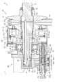
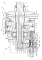
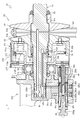
- FIG. 1 is a side cross-sectional view showing an overall configuration of a transmission including a belt type continuously variable transmission according to an embodiment of the present invention.
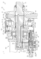
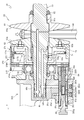
- Side surface sectional drawing which shows the input pulley of a belt-type continuously variable transmission, a hydraulic cylinder, a hydraulic servo mechanism, etc.
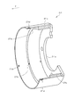
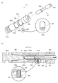
- the perspective view which shows a movable side cylinder case.
- the perspective view which shows a contact member.
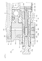
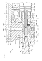
- the side surface sectional enlarged view which shows a servo spool and a feedback spool.
- the perspective view which shows the link mechanism connected with a servo spool.
- Side surface sectional drawing which shows the case where a servo spool slides back.
- Side surface sectional drawing which shows the case where an input side movable sheave slides back.
- the transmission 7 that is a transmission of the work vehicle will be described with reference to FIG.
- the transmission 7 according to the present embodiment is described as being provided in a tractor that is an agricultural vehicle, but the present invention is not limited to this, and other vehicles such as other agricultural vehicles, construction vehicles, and industrial vehicles can be used. It can be applied in general.
- the direction of arrow F in the figure is defined as the forward direction.
- the transmission 7 outputs power after shifting power from an engine (not shown) as a drive source.
- the transmission 7 includes a transmission input shaft 20, a clutch mechanism 200, a belt-type continuously variable transmission 40, an output shaft 170, a front wheel drive transmission shaft 180, a PTO brake 210, a PTO input shaft 220, a rear PTO shaft 230, and a mid PTO shaft 240. Etc.
- the power from the engine is transmitted to the mission input shaft 20 and then transmitted to the belt type continuously variable transmission 40 and the PTO input shaft 220 via the clutch mechanism 200.
- the power transmitted to the belt-type continuously variable transmission 40 is continuously shifted in the belt-type continuously variable transmission 40 and then transmitted to the output shaft 170 and the front wheel drive transmission shaft 180.
- the power transmitted to the output shaft 170 is transmitted to a rear wheel (not shown) of the tractor via a final speed reduction mechanism (not shown).
- the power transmitted to the front wheel drive transmission shaft 180 is transmitted to the front wheels (not shown) of the tractor via the front axle (not shown).
- the power transmitted to the PTO input shaft 220 is transmitted to the rear PTO shaft 230 and the mid PTO shaft 240 through gears and the like.
- the vehicle speed of the tractor can be arbitrarily adjusted by changing the gear ratio in the belt type continuously variable transmission 40.
- a working machine for example, a rotary tiller or the like
- a working machine coupled to the mid PTO shaft 240 for example, a rotary tiller
- the mid PTO shaft 240 for example, a rotary tiller
- a midmore can be driven.
- the transmission of power from the engine to the PTO input shaft 220 is interrupted by the clutch mechanism 200, the rotation of the PTO input shaft 220 is braked by the PTO brake 210.
- the belt-type continuously variable transmission 40 can be applied to transmissions other than the transmission 7 according to this embodiment, and can be widely applied to transmissions that output power after shifting power from a drive source. is there.
- the belt type continuously variable transmission 40 includes a transmission input shaft 50, an input pulley 60, a hydraulic cylinder 270, a hydraulic servo mechanism 280, a transmission shaft 90, an output pulley 100, an output member 110, a cam mechanism 120, a biasing member 130, and a belt 140. And a planetary gear mechanism 150 and the like.
- the transmission input shaft 50 shown in FIGS. 1 and 2 is connected to the mission input shaft 20 and transmits power from the mission input shaft 20.
- the transmission input shaft 50 is a substantially cylindrical member, and is arranged with the axial direction as the front-rear direction. In the vicinity of the rear end portion of the transmission input shaft 50, the transmission input gear 51 is connected to the transmission input shaft 50 so as not to rotate relative thereto by spline fitting.
- the transmission input gear 51 is meshed with the gear of the clutch mechanism 200 (see FIG. 1), and the power of the mission input shaft 20 can be transmitted through the clutch mechanism 200.
- the method of connecting the transmission input gear 51 to the transmission input shaft 50 is not limited to the spline fitting, and the transmission input gear 51 can be formed integrally with the transmission input shaft 50 or the like.
- the bearing 52 is fitted to the speed change input shaft 50. Further, the bearing 53 is fitted to the transmission input shaft 50 in the vicinity of the front end portion of the transmission input shaft 50. Since the bearing 52 and the bearing 53 are supported by the transmission case 8 that houses the transmission 7, the transmission input shaft 50 is rotatably supported by the transmission case 8.
- the input pulley 60 shown in FIG. 2 is a pulley disposed on the transmission input shaft 50 and having a pair of sheaves.
- the input pulley 60 includes an input side fixed sheave 61, an input side movable sheave 63, and the like.
- the input side fixed sheave 61 is a member having a substantially cylindrical shaft tube portion and a substantially frustoconical sheave portion formed integrally with the front end of the shaft tube portion in a side sectional view.
- the input side fixed sheave 61 is fitted on the transmission input shaft 50 with the sheave portion disposed in front of the shaft tube portion.
- the front surface 61a of the sheave portion of the input side fixed sheave 61 is formed as an inclined surface whose diameter increases from the front to the rear.
- a through hole 61b that penetrates the input side fixed sheave 61 in the front-rear direction is formed.
- the transmission input shaft 50 is inserted into the through hole 61b of the input side fixed sheave 61 from the front.
- the input side fixed sheave 61 is fixed to the speed change input shaft 50 so as not to rotate relative to the speed change input shaft.
- the speed change input shaft 50 and the input side fixed sheave 61 are fitted (fitted) by press fitting, but the speed change input shaft 50 such as “shrink fit” or “cool fit” is used. Any method may be used as long as the diameter is larger than the diameter of the through hole 61 b of the input side fixed sheave 61.
- the lock nut 62 is fastened to the transmission input shaft 50 immediately behind the input side fixed sheave 61. As a result, the input-side fixed sheave 61 can be prevented from sliding backward on the transmission input shaft 50, and the input-side fixed sheave 61 can be securely fixed to the transmission input shaft 50.
- the input side movable sheave 63 is a member having a substantially cylindrical shaft tube portion and a substantially frustoconical sheave portion formed integrally with the rear end of the shaft tube portion in a side sectional view.
- the input-side movable sheave 63 is fitted on the transmission input shaft 50 in front of the input-side fixed sheave 61 with the sheave portion disposed behind the shaft tube portion.
- the rear surface 63a of the sheave portion of the input side movable sheave 63 is formed as an inclined surface whose diameter increases from the rear to the front.
- a through hole 63b that penetrates the input side movable sheave 63 in the front-rear direction is formed on the axis of the input side movable sheave 63.
- the transmission input shaft 50 is inserted through the through hole 63b of the input side movable sheave 63 from the rear.
- the Grooves are formed in the inner peripheral surface of the through hole 63b and the outer peripheral surface of the transmission input shaft 50 along the axial direction of the transmission input shaft 50, respectively.
- the grooves are formed at three equal intervals in the circumferential direction of the inner peripheral surface of the through-hole 63b and the outer peripheral surface of the transmission input shaft 50, and steel balls 64, 64... Is placed.
- the input side movable sheave 63 is supported so as to be slidable in the axial direction with respect to the transmission input shaft 50 and not to be relatively rotatable.
- the input side movable sheave 63 is formed with a through hole 63d that communicates the outer peripheral surface of the shaft tube portion with the inner peripheral surface of the through hole 63b.
- the hydraulic cylinder 270 is formed on the input side movable sheave 63 and is used for sliding the input side movable sheave 63 on the speed change input shaft 50 in the axial direction thereof.
- the hydraulic cylinder 270 includes a movable cylinder case 271 and a fixed cylinder case 73.
- the movable cylinder case 271 shown in FIGS. 2 and 3 is a cylindrical member having a bottom surface (rear surface) and an open front portion.
- a through hole 271a is formed in the axial direction at the center of the rear surface of the movable cylinder case 271, and the shaft cylinder portion of the input movable sheave 63 is inserted through the through hole 271a.
- the thick part 271b is formed so that the outer peripheral surface is thicker than the other part (front end side) from the front and rear substantially center to the rear end of the cylindrical part of the movable cylinder case 271.
- the outer peripheral surface of the cylindrical portion of the movable cylinder case 271 is uniform, and the inner peripheral surface of the thick portion 271b protrudes toward the inner side of the movable cylinder case 271 from the inner peripheral surface of the other portion. Become.
- the communication hole 271c includes a horizontal hole having a circular cross section formed in the front-rear direction from the front end surface of the thick portion 271b (portion located inside the movable cylinder case 271) to the vicinity of the rear surface of the movable cylinder case 271, and the horizontal hole And a vertical hole that communicates the inside of the movable cylinder case 271 with the vicinity of the rear surface of the movable cylinder case 271.
- Three communication holes 271c are formed at equal intervals in the circumferential direction of the thick portion 271b. The intervals between the communication holes 271c are not limited to equal intervals, and the number of the communication holes 271c is not limited to the above number.
- the sliding member 277 is slidably inserted into the lateral hole of the communication hole 271c.
- the sliding member 277 is a substantially cylindrical member.
- the outer diameter of the sliding member 277 is formed to be substantially the same as the inner diameter of the communication hole 271c (specifically, slightly smaller than the inner diameter of the communication hole 271c so as to be slidable).
- the longitudinal direction (front-rear direction) length of the sliding member 277 is formed to be substantially the same as the longitudinal direction length of the lateral hole of the communication hole 271c.
- Through holes 271d, 271d,... are formed in the vicinity of the front end of the cylindrical portion of the movable cylinder case 271.
- the through hole 271d is formed so as to penetrate the outer peripheral surface and the inner peripheral surface of the cylindrical portion of the movable cylinder case 271.
- Three through holes 271d are formed at equal intervals in the circumferential direction of the movable cylinder case 271.
- the interval between the through holes 271d is not limited to an equal interval, and the number of the through holes 271d is not limited to the above number.
- the movable cylinder case 271 is in the input side in a state where the front surface of the sheave portion of the input movable sheave 63 and the rear surface of the movable cylinder case 271 are brought into contact with each other by a fastener such as a bolt.
- a fastener such as a bolt.
- the movable cylinder case 271 and the input movable sheave 63 can be integrally formed by forging or the like.
- the fixed cylinder case 73 is a member having a box-shaped part whose rear part is opened and an annular flange part integrally formed at the rear end of the box-shaped part.
- a through hole 73a is formed in the center of the front surface of the fixed cylinder case 73, and the speed change input shaft 50 is inserted through the through hole 73a.
- the rear portion (the flange portion) of the fixed side cylinder case 73 is inserted into the movable side cylinder case 271 from the open side (front side) of the movable side cylinder case 271. More specifically, the rear portion (saddle portion) of the fixed cylinder case 73 is inserted into the thick portion 271b of the movable cylinder case 271.
- a seal member 74 is disposed between the fixed cylinder case 73 and the thick part 271b of the movable cylinder case 271.
- the contact member 278F and the contact member 278R are inserted inside the vicinity of the open side (front) end of the movable-side cylinder case 271.
- the contact member 278F and the contact member 278R shown in FIGS. 2 and 4 are formed to have a shape (annular shape) in which a hole is provided at the center of a circular plate-like member.
- the outer diameters of the contact member 278F and the contact member 278R are substantially the same as the inner diameter of the cylindrical portion of the movable-side cylinder case 271 (specifically, the front side of the cylindrical portion (the portion that is not the thick portion 271b)).
- An oil groove 278a is formed on the rear surface of the contact member 278F so as to communicate the inner peripheral surface and the outer peripheral surface of the contact member 278F.
- an oil groove 278b is formed on the front surface of the contact member 278R so as to communicate the inner peripheral surface and the outer peripheral surface of the contact member 278R.
- the transmission input shaft 50 is inserted into the above-described bearing 53, and is supported rotatably with respect to the transmission case 8 via the bearing 53.
- a lock nut 75 is fastened to the transmission input shaft 50 immediately in front of the bearing 53. Accordingly, the bearing 53 can be prevented from sliding forward, and the stationary cylinder case 73 can be prevented from sliding forward via the bearing 53. Further, the bearing 53, the fixed side cylinder case 73, the movable side cylinder case 271, the input side movable sheave 63, the belt 140, and the input side fixed sheave 61 are sandwiched between the lock nut 62 and the lock nut 75, and the torque applied to each member. Can be confined between the lock nut 62 and the lock nut 75.
- the hydraulic cylinder 270 is provided on the input side movable sheave 63 of the input pulley 60. Further, in the hydraulic cylinder 270 configured as described above, a hydraulic chamber 76 is formed in a space closed by the input side movable sheave 63, the movable side cylinder case 271, the fixed side cylinder case 73, and the transmission input shaft 50. .., The contact member 278F, the contact member 278R, the restriction member 279, 279, and the communication holes 271c, 271c,. A spool position holding mechanism according to the invention is configured.
- the hydraulic servo mechanism 280 shown in FIGS. 2 and 5 is for controlling the supply of hydraulic oil to the hydraulic cylinder 270 and thus for controlling the operation of the input side movable sheave 63 via the hydraulic cylinder 270.
- the hydraulic servo mechanism 280 includes a front case 81, a servo spool 283, a feedback spool 84, a spool spring 85, and the like.
- the front case 81 is a member in which an oil passage for guiding hydraulic oil is formed.
- the front case 81 is formed with a valve chamber 81a, a bearing hole 81b, a hydraulic oil port 81c, a communication oil path 81d, and the like.
- the valve chamber 81a is a through hole having a circular cross section formed so as to communicate the front surface and the rear surface of the front case 81.
- the valve chamber 81a is formed with the axial direction as the front-rear direction. Further, the valve chamber 81 a is formed so as to overlap the input side movable sheave 63 of the input pulley 60 in a front view, that is, at a position facing the input side movable sheave 63.
- the bearing hole 81b is a hole having a circular cross section formed from the rear surface of the front case 81 to the vicinity of the front end.
- the bearing hole 81b is formed with the axial direction as the front-rear direction.
- the front end portion of the transmission input shaft 50 is inserted through the bearing hole 81b from the rear.
- the hydraulic oil port 81c is a through hole formed so as to communicate the side surface of the main body of the front case 81 and the valve chamber 81a. More specifically, the hydraulic oil port 81c communicates the side surface of the main body portion of the front case 81 and a portion located slightly ahead of the approximate center in the axial direction of the valve chamber 81a.
- the hydraulic oil port 81c is connected to a hydraulic oil pump (not shown) by piping or the like.
- the hydraulic oil port 81c only needs to communicate with the outside of the front case 81 and the valve chamber 81a, and does not limit the shape and size of the hole.
- the communicating oil passage 81d is an oil passage formed to communicate the valve chamber 81a and the bearing hole 81b. More specifically, the communication oil passage 81d communicates a portion located slightly rearward from the substantially axial center of the valve chamber 81a and a substantially central portion of the bearing hole 81b in the axial direction.
- Servo spool 283 is for switching the oil path in hydraulic servo mechanism 280.
- the servo spool 283 is a substantially columnar member, and an enlarged diameter portion having a larger diameter than other portions is formed at the rear end portion.
- the servo spool 283 is arranged with the axial direction as the front-rear direction.
- the servo spool 283 is formed with a sliding hole 283a, a first groove 283b, a second groove 283c, a first through hole 283d, a second through hole 283e, a discharge oil passage 283f, and the like.
- the sliding hole 283a is a through hole having a circular cross section formed so as to penetrate from the rear end to the front end of the servo spool 283 on the axis of the servo spool 283.
- the front end of the sliding hole 283a is closed by a lid member 283g.
- the first groove 283b is formed along the outer periphery of the servo spool 283 slightly ahead of the approximate center in the axial direction of the servo spool 283. As will be described later, even when the servo spool 283 slides in the axial direction with respect to the valve chamber 81a of the front case 81, the first groove 283b is always formed regardless of the sliding position of the servo spool 283.
- the first groove 283b is formed long in the axial direction of the servo spool 283 so as to face the hydraulic oil port 81c.
- the second groove 283 c is formed along the outer periphery of the servo spool 283 behind the first groove 283 b of the servo spool 283. As will be described later, even when the servo spool 283 slides in the axial direction with respect to the valve chamber 81a of the front case 81, the second groove 283c is always formed regardless of the sliding position of the servo spool 283.
- the second groove 283 c is formed long in the axial direction of the servo spool 283 so as to face the communication oil path 81 d.
- the first through hole 283d is formed so that the first groove 283b and the sliding hole 283a are in communication with each other with the axis direction orthogonal to the axis of the servo spool 283.
- the second through hole 283e is formed so that the second groove 283c and the sliding hole 283a communicate with each other with the axial direction orthogonal to the axial line of the servo spool 283.
- the drain oil passage 283f is an oil passage formed to communicate the rear end of the servo spool 283 and the sliding hole 283a. More specifically, the drain oil passage 283f communicates the rear end of the servo spool 283 and a portion behind the portion facing the second groove 283c of the sliding hole 283a.
- the outer diameter of the servo spool 283 is formed to be substantially the same as the inner diameter of the valve chamber 81a of the front case 81.
- the servo spool 283 is slidably inserted through the valve chamber 81a of the front case 81 from the rear.
- the diameter of the enlarged diameter portion of the servo spool 283 is formed to be larger than the diameter of the valve chamber 81a of the front case 81, and when the enlarged diameter portion abuts the front case 81, the servo spool 283 slides forward at a predetermined position. It is regulated by. Further, as shown in FIG.
- the front end portion (lid member 283 g) of the servo spool 283 protrudes forward from the front surface of the front case 81.
- the front end portion (lid member 283g) of the servo spool 283 is connected to a transmission operation tool (not shown) such as a transmission lever or a transmission pedal via the link mechanism 8a, and the servo spool 283 is operated by operating the transmission operation tool. It is possible to slide in the front-rear direction.
- the link mechanism 8a is provided with a return spring 8b. By the return spring 8b, the link mechanism 8a is urged to always return to the neutral position, and as a result, the servo spool 283 is urged to always return to the neutral position.
- the “neutral position” of the servo spool 283 means that power is not transmitted to the output shaft 170 as a result of the power from the engine being shifted in the belt-type continuously variable transmission 40 (the rotation speed of the output shaft 170 is 0).
- the feedback spool 84 shown in FIGS. 2 and 5 is for switching the oil path in the hydraulic servo mechanism 280.
- the feedback spool 84 is a substantially cylindrical member.
- the feedback spool 84 is arranged with the axial direction as the front-rear direction.
- the feedback spool 84 is formed with a discharge oil passage 84a, a communication groove 84b, and the like.
- the drain oil passage 84 a is an oil passage formed so as to communicate the front end and the rear end of the feedback spool 84 on the axis of the feedback spool 84.
- the communication groove 84 b is formed along the outer periphery of the feedback spool 84 at a substantially central portion in the axial direction of the feedback spool 84.
- the outer diameter of the feedback spool 84 is formed to be substantially the same as the inner diameter of the sliding hole 283a of the servo spool 283.
- the feedback spool 84 is slidably inserted into the sliding hole 283a of the servo spool 283. As a result, the feedback spool 84 can slide in the front-rear direction with respect to the servo spool 283.
- the spool spring 85 biases the feedback spool 84 backward.
- the spool spring 85 is constituted by a compression coil spring.
- the spool spring 85 is disposed in the sliding hole 283a of the servo spool 283 and constantly urges the feedback spool 84 rearward (that is, the input side movable sheave 63 side).
- the member for biasing is not limited to the compression coil spring (spool spring 85).
- a first groove 50c, an operating groove 50e, and a hydraulic oil path 50f are formed in the transmission input shaft 50 shown in FIG.
- the first groove 50 c is formed along the outer periphery of the transmission input shaft 50 in the vicinity of the front end portion in the axial direction of the transmission input shaft 50. More specifically, the first groove 50c is formed at an axial position facing the communication oil passage 81d formed in the front case 81 when the transmission input shaft 50 is inserted into the bearing hole 81b of the front case 81. Is done.
- the operation groove 50 e is formed in a part of the outer peripheral surface of the transmission input shaft 50 in the middle of the transmission input shaft 50 in the axial direction. More specifically, the operating groove 50e is formed at a position facing the through hole 63d formed in the input side movable sheave 63 when the input side movable sheave 63 is supported on the transmission input shaft 50.
- the operation groove 50e Even when the input-side movable sheave 63 slides in the axial direction with respect to the transmission input shaft 50, the operation groove 50e always faces the through hole 63d regardless of the sliding position of the movable sheave.
- the operating groove 50e is formed long in the axial direction of the transmission input shaft 50.
- the hydraulic oil passage 50f is a hole formed from the front end of the speed change input shaft 50 to the substantially same position as the operation groove 50e in the axial direction.
- the front end of the hydraulic oil passage 50f is closed by a plug.
- the hydraulic oil passage 50f communicates with the first groove 50c in the vicinity of the front end portion and the operating groove 50e in the vicinity of the rear end portion.
- a constant pressure is applied to the (through hole 63d) and the hydraulic chamber 76 by the hydraulic oil pumped from the hydraulic oil pump.
- the pressure of the hydraulic oil is applied to the rear end of the sliding member 277 through a communication hole 271 c formed in the movable cylinder case 271. Due to the pressure, the sliding member 277 slides forward.
- the front end of the sliding member 277 contacts the rear surface of the contact member 278R, and the sliding member 277 pushes the contact member 278R and the contact member 278F forward, so that the contact member 278R and the contact member 278F also slides forward.
- the contact member 278R and the contact member 278F slide forward to a position where they come into contact with the regulating member 279, and are held at these positions.
- the feedback spool 84 that abuts against the abutting member 278F from the front is held in a state of being pushed to a predetermined position with respect to the sliding hole 283a of the servo spool 283 against the biasing force of the spool spring 85.
- the “predetermined position” of the feedback spool 84 is a relative position with respect to the servo spool 283, and more specifically, by the outer peripheral surface of the feedback spool 84 (specifically, the outer peripheral surface in front of the communication groove 84b). This is a position where the first through hole 283d of the servo spool 283 is closed and the discharge oil path 283f of the servo spool 283 is closed by the outer peripheral surface of the feedback spool 84 (specifically, the outer peripheral surface behind the communication groove 84b).
- the hydraulic oil pumped from the hydraulic oil pump is supplied to the first groove 283b of the servo spool 283 via the hydraulic oil port 81c of the front case 81.
- the first through hole 283 d that communicates the first groove 283 b and the sliding hole 283 a is closed by the outer peripheral surface of the feedback spool 84. Therefore, the hydraulic oil supplied from the hydraulic oil pump is blocked by the feedback spool 84 and is not supplied to the hydraulic chamber 76 of the hydraulic cylinder 270.
- the input side movable sheave 63 is biased forward by the tension of a belt 140 (described later) wound around the input pulley 60, the input side movable sheave 63 and the movable side cylinder case 271 slide forward. It is held in the state.
- the servo spool 283 slides backward, whereas the feedback spool 84 cannot slide backward because it is in contact with the contact member 278F. Therefore, the feedback spool 84 slides forward relative to the servo spool 283. Accordingly, the communication groove 84b of the feedback spool 84 faces the first through hole 283d and the second through hole 283e of the servo spool 283, and the hydraulic oil supplied from the hydraulic oil pump to the hydraulic oil port 81c is The oil is supplied to the communication oil passage 81d through the groove 283b, the first through hole 283d, the communication groove 84b, the second groove 283c, and the second through hole 283e.
- the hydraulic oil supplied to the communication oil path 81d is further supplied to the hydraulic chamber 76 via the first groove 50c of the speed change input shaft 50, the hydraulic oil path 50f, the operating groove 50e, and the through hole 63d of the input side movable sheave 63. Supplied.
- the pressure in the hydraulic chamber 76 increases, and the input side movable sheave 63 and the movable side cylinder case 271 are urged rearward by the pressure.
- the input side movable sheave 63 and the movable side cylinder case 271 urged rearward by the pressure of the hydraulic oil in this manner slide rearward against the forward urging force due to the tension of the belt 140 ( (See FIG. 8).
- the contact member 278F and the contact member 278R also move rearward together with the movable side cylinder case 271.
- the feedback spool 84 that is in contact with the contact member 278F while being urged from the front also slides rearward. That is, the feedback spool 84 slides backward relative to the servo spool 283.
- the feedback spool 84 in contact with the contact member 278F also slides forward. That is, the feedback spool 84 slides forward relative to the servo spool 283.
- the feedback spool 84 slides to a predetermined position together with the input-side movable sheave 63 and the movable-side cylinder case 271, and the first through hole 283 d of the servo spool 283 is closed again by the outer peripheral surface of the feedback spool 84, the hydraulic cylinder 270.
- the supply of hydraulic oil to the hydraulic chamber 76 ends.
- the feedback spool 84 slides following the input-side movable sheave 63 and the movable-side cylinder case 271 and switches the oil passage communicating with the hydraulic chamber 76, whereby the input-side movable sheave 63 and the movable-side cylinder are switched.
- the case 271 can be held at a position corresponding to the sliding position of the servo spool 283.
- the servo spool 283 slides forward, whereas the feedback spool 84 is urged toward the contact member 278F by the spool spring 85, so that the feedback spool 84 is moved toward the contact member 278F. It is held in contact. Therefore, the feedback spool 84 slides backward relative to the servo spool 283.
- the communication groove 84b of the feedback spool 84 faces the second through hole 283e and the discharge oil passage 283f of the servo spool 283, and the hydraulic oil enters the discharge oil passage 283f through the second groove 283c and the second through hole 283e. And can be distributed.
- the input side movable sheave 63 and the movable side cylinder case 271 are biased forward by the tension of the belt 140. Therefore, the hydraulic oil in the hydraulic chamber 76 of the hydraulic cylinder 270 is pushed out by the input side movable sheave 63 and the movable side cylinder case 271, and the through hole 63d of the input side movable sheave 63, the operation groove 50e of the transmission input shaft 50, the operation.
- the servo via the oil passage 50f, the first groove 50c, the communication oil passage 81d, the second groove 283c of the servo spool 283, the second through hole 283e, the communication groove 84b of the feedback spool 84 and the discharge oil passage 283f of the servo spool 283.
- the spool 283 is discharged rearward from the rear end.
- the contact member 278F can be lubricated by the hydraulic oil discharged from the rear end of the servo spool 283. Further, when the hydraulic oil in the hydraulic chamber 76 is discharged, the input side movable sheave 63 and the movable side cylinder case 271 slide forward according to the urging force from the belt 140 (see FIG. 2).
- the first through hole 283d of the servo spool 283 remains closed by the outer peripheral surface of the feedback spool 84, and the hydraulic oil from the hydraulic oil pump is supplied to the hydraulic chamber 76 of the hydraulic cylinder 270. There is no.
- the feedback spool 84 in contact with the contact member 278F also slides forward. That is, the feedback spool 84 slides forward relative to the servo spool 283.
- the input side movable sheave 63 can be slid to a desired position by sliding the servo spool 283 to an arbitrary position. Further, the input movable sheave 63 can be held at a desired sliding position by the feedback spool 84 that slides following the input movable sheave 63.
- the input side movable sheave 63 is slid using the hydraulic servo mechanism 280.
- the present invention is not limited to this, and an output pulley described later using the hydraulic servo mechanism 280. It is also possible to have a configuration in which 100 output-side movable sheaves 103 are slid.
- the transmission shaft 90 shown in FIGS. 1 and 12 transmits power from the transmission input shaft 50.
- the transmission shaft 90 is a substantially cylindrical member, and is arranged with the axial direction as the front-rear direction.
- a bearing 91 is fitted in the vicinity of the front end portion of the transmission shaft 90. By supporting the bearing 91 on the transmission case 8, the transmission shaft 90 is rotatably supported on the transmission case 8.
- the output pulley 100 shown in FIG. 12 is a pulley that is disposed on the transmission shaft 90 and includes a pair of sheaves.
- the output pulley 100 includes an output side fixed sheave 101, an output side movable sheave 103, and the like.
- the output side fixed sheave 101 is a member made of the same material as the input side fixed sheave 61 and formed in the same shape. That is, the output-side fixed sheave 101 is a member having a substantially cylindrical shaft tube portion and a substantially frustoconical sheave portion formed integrally with the rear end of the shaft tube portion in a side sectional view. .
- the output side fixed sheave 101 is fitted on the transmission shaft 90 with the sheave portion disposed behind the shaft tube portion.
- the rear surface 101a of the sheave portion of the output side fixed sheave 101 is formed as an inclined surface whose diameter increases from the rear to the front.
- a through hole 101b that penetrates the output side fixed sheave 101 in the front-rear direction is formed on the axis of the output side fixed sheave 101.
- a transmission shaft 90 is inserted into the through hole 101b of the output side fixed sheave 101 from the rear.
- the output side fixed sheave 101 is fixed to the transmission shaft 90 so that it cannot rotate relative to the transmission shaft 90 and cannot slide.
- the transmission shaft 90 and the output side fixed sheave 101 are fitted (fitted) by press fitting, but the diameter of the transmission shaft 90 such as “shrink fit” or “cool fit” is used. May be a method of fitting using the fact that the diameter is larger than the diameter of the through hole 101b of the output side fixed sheave 101.
- the transmission shaft 90 is inserted into the above-described bearing 91, and is rotatably supported with respect to the transmission case 8 via the bearing 91.
- the lock nut 102 is fastened to the transmission shaft 90. Accordingly, the bearing 91 can be prevented from sliding forward, and the output-side fixed sheave 101 can be prevented from sliding forward via the bearing 91, so that the output-side fixed sheave 101 can be connected to the transmission shaft 90. Can be securely fixed.
- the output side movable sheave 103 is a member made of the same material as the input side movable sheave 63 and formed in the same shape. That is, the output-side movable sheave 103 is a member having a substantially cylindrical shaft tube portion and a substantially frustoconical sheave portion formed integrally with the rear end of the shaft tube portion in a side sectional view. .
- the output-side movable sheave 103 is fitted on the transmission shaft 90 behind the output-side fixed sheave 101 with the sheave portion disposed in front of the shaft tube portion.
- the front surface 103a of the sheave portion of the output side movable sheave 103 is formed as an inclined surface whose diameter increases from the front to the rear.
- a through hole 103b that penetrates the output side movable sheave 103 in the front-rear direction is formed on the axis of the output side movable sheave 103.
- the transmission shaft 90 is inserted into the through hole 103b of the output side movable sheave 103 from the front.
- Grooves are formed in the inner peripheral surface of the through hole 103b and the outer peripheral surface of the transmission shaft 90 along the axial direction of the transmission shaft 90, respectively. Three grooves are formed at equal intervals in the circumferential direction of the inner peripheral surface of the through-hole 103b and the outer peripheral surface of the transmission shaft 90, and steel balls 104, 104. Be placed. Thereby, the output side movable sheave 103 is supported so as to be slidable in the axial direction with respect to the transmission shaft 90 and not to be relatively rotatable.
- the input-side fixed sheave 61 and the input-side movable sheave 63 of the input pulley 60 and the output-side fixed sheave 101 and the output-side movable sheave 103 of the output pulley 100 are shared by the same parts, so that Can be reduced, and as a result, the cost of parts can be reduced.
- the output member 110 is for transmitting the power from the cam mechanism 120 to the planetary gear mechanism 150.
- the output member 110 is a member having a substantially cylindrical shaft tube portion having a bottom surface (rear surface) and an annular flange portion formed integrally with the front end of the shaft tube portion.
- the output member 110 is disposed behind the output pulley 100 with the transmission shaft 90 inserted through the through hole of the output member 110.
- the cam mechanism 120 enables transmission of torque between the output pulley 100 and the output member 110.
- the cam mechanism 120 includes a first cam 121, a second cam 122, and the like.
- the first cam 121 is a substantially cylindrical member.
- the first cam 121 is disposed so that the axial direction is directed in the front-rear direction and the axial line coincides with the axial line of the transmission shaft 90.
- a through hole having a predetermined inner diameter is formed on the axis of the first cam 121.
- a plane perpendicular to the axial direction is formed on the front surface of the first cam 121, and a plurality of surfaces that are inclined at a predetermined angle with respect to the surface orthogonal to the axial direction are formed on the rear surface of the first cam 121.
- the shaft tube portion of the output side movable sheave 103 is inserted through the through hole of the first cam 121 from the front.
- the first cam 121 is fixed to the output side movable sheave 103 in a state where the rear surface of the sheave portion of the output side movable sheave 103 and the front surface of the first cam 121 are brought into contact with each other by a fastener such as a bolt or welding. Is done.
- a fastener such as a bolt or welding.
- the first cam 121 and the output-side movable sheave 103 can be integrally formed by forging or the like.
- the second cam 122 is a member made of the same material as the first cam 121 and formed in the same shape. That is, the second cam 122 is disposed so that the axial direction is directed in the front-rear direction and the axial line coincides with the axial line of the transmission shaft 90.
- a through hole having a predetermined inner diameter is formed on the axis of the second cam 122.
- On the rear surface of the second cam 122 a plane perpendicular to the axial direction is formed, and on the front surface of the second cam 122, a plurality of surfaces inclined by a predetermined angle with respect to the surface orthogonal to the axial direction are formed.
- the transmission shaft 90 is inserted into the through hole of the second cam 122 from the front.
- the second cam 122 is fixed to the output member 110 in a state where the front surface of the output member 110 and the rear surface of the second cam 122 are brought into contact with each other by a fastener such as a bolt or welding.
- a fastener such as a bolt or welding.
- the rear surface of the first cam 121 and the front surface of the second cam 122 are arranged to face each other.
- the second cam 122 and the output member 110 can be integrally formed by forging or the like.
- the urging member 130 urges the output side movable sheave 103 forward.
- the biasing member 130 is disposed in the output member 110 and is configured by a plurality of disc springs 131, 131,... Arranged in the axial direction.
- the rear end of the biasing member 130 (the disc spring 131 disposed at the rearmost position) is in contact with the output member 110, and the front end of the biasing member 130 (the disc spring 131 disposed at the frontmost position) is interposed via the inner guide member 132.
- the output side movable sheave 103 is brought into contact with the rear end.
- the belt 140 is a metal belt including a band in which metal thin plates are stacked and a metal element.
- the present invention is not limited to this, and a belt made of rubber, a chain, or a resin may be used as the belt 140.
- the belt 140 wound around the groove of the input pulley 60 is clamped by the input pulley 60 when the input side movable sheave 63 is pushed toward the input side fixed sheave 61 by the hydraulic cylinder 270 with a predetermined force.
- the belt 140 wound around the groove of the output pulley 100 is pushed to the output pulley 100 by the output side movable sheave 103 being pushed toward the output side fixed sheave 101 side with a predetermined force by the urging force of the urging member 130. It is pinched.
- the planetary gear mechanism 150 is for synthesizing and outputting two powers.
- the planetary gear mechanism includes a sun gear 151, a ring gear 152, a carrier gear 153, planetary shafts 155, 155, connecting shafts 156, 156, planetary gears 157, 157, a support member 159, a planetary output member 163, and the like. It has.
- the sun gear 151 is supported by the transmission shaft 90 so as to be relatively rotatable immediately behind the output member 110. Teeth are formed at the front end portion and the rear end portion of the sun gear 151, and the front end portion of the sun gear 151 is spline-fitted with the output member 110.
- the ring gear 152 is a gear having teeth formed on the inner peripheral surface of the annular member. Ring gear 152 is disposed outside the rear end of sun gear 151.
- the carrier gear 153 is a gear having teeth formed on the outer peripheral surface of a substantially circular plate-like member.
- the carrier gear 153 is supported on the midway part of the sun gear 151 so as to be relatively rotatable.
- the teeth of the carrier gear 153 are engaged with the gear of the clutch mechanism 200 provided on the mission input shaft 20, and the power of the mission input shaft 20 can be transmitted through the clutch mechanism 200.
- the planetary shafts 155, 155, ... are substantially cylindrical members.
- the planetary shafts 155, 155... Are fixed to the carrier gear 153 by fitting one ends (front ends) of the planetary shafts 155, 155.
- the other end (rear end) of the planetary shafts 155, 155... Extends rearward.
- Three planetary shafts 155, 155... Are arranged on the same circumference with the transmission shaft 90 as the center.
- the connecting shafts 156, 156... are substantially cylindrical members. One end (front end) of the connecting shafts 156, 156... Is fitted into a through-hole formed in the carrier gear 153, whereby the connecting shafts 156, 156. The other ends (rear ends) of the connecting shafts 156 and 156 extend rearward. Three connecting shafts 156, 156,... Are arranged alternately with planetary shafts 155, 155,.
- Planetary gears 157, 157... Are three gears that mesh with the teeth of the sun gear 151 and the teeth of the ring gear 152, respectively.
- the planetary gears 157, 157,... are inserted into the planetary gears 157, 157, respectively, and the planetary gears 157, 157,.
- the support member 159 is a member having a substantially cylindrical shaft tube portion and an annular flange formed integrally with the front end of the shaft tube portion.
- the support member 159 is supported on the transmission shaft 90 via a bearing immediately behind the sun gear 151 so as to be relatively rotatable.
- the other ends of the planetary shafts 155, 155, and the other ends of the connecting shafts 156, 156, and the like are fitted into the through holes formed in the flange portion of the support member 159, respectively.
- the planetary output member 163 is a box-shaped member whose front part is opened. A through hole is formed at the center of the rear surface of the planetary output member 163.
- the planetary output member 163 is disposed so as to cover the rear end portion of the transmission shaft 90 and the support member 159 from the rear of the transmission shaft 90. The vicinity of the front and rear center part of the planetary output member 163 is supported by the transmission shaft 90 via a bearing so as to be relatively rotatable.
- the front end of the planetary output member 163 is fastened to the ring gear 152 by a bolt, and is connected so as to be rotatable integrally with the ring gear 152.
- the planetary output member 163 and the ring gear 152 can be integrally formed by forging or the like.
- the output shaft 170 is splined to the rear end of the planetary output member 163. Power from the planetary output member 163 can be transmitted to the rear wheel (not shown) of the tractor and the front wheel drive transmission shaft 180 via the output shaft 170.
- the input pulley 60 When power from the engine is transmitted to the transmission input shaft 50 via the mission input shaft 20 and the clutch mechanism 200, the input pulley 60 is also rotated together with the transmission input shaft 50.
- the output pulley 100 is rotated via the belt 140.
- the first cam 121 fixed to the output pulley 100 is rotated.
- the second cam 122 When the second cam 122 is rotated, the sun gear 151 of the planetary gear mechanism 150 is rotated via the output member 110.
- the sun gear 151 When the sun gear 151 is rotated, the planetary gears 157, 157... Meshed with the sun gear 151 rotate (rotate) around the planetary shafts 155, 155.
- the power from the engine is transmitted to the carrier gear 153 of the planetary gear mechanism 150 via the mission input shaft 20 and the clutch mechanism 200 (that is, not shifted by the input pulley 60, the output pulley 100, and the belt 140). Then, together with the carrier gear 153, planetary gears 157, 157... Supported by the carrier gear 153 rotate (revolve) around the transmission shaft 90.
- the power transmitted from the mission input shaft 20 to the planetary gear mechanism 150 via the belt 140 and the power transmitted from the mission input shaft 20 directly to the planetary gear mechanism 150 without passing through the belt 140 are the planets. Are combined by planetary gears 157, 157. The combined power is transmitted to the output shaft 170 through the ring gear 152 meshed with the planetary gears 157, 157.
- the cam mechanism 120 can apply a forward biasing force to the output side movable sheave 103 according to the torque transmitted from the first cam 121 to the second cam 122. Specifically, twisting occurs between the first cam 121 and the second cam 122 according to the torque transmitted by the cam mechanism 120. In this case, since the rear surface (inclined surface) of the first cam 121 and the front surface (inclined surface) of the second cam 122 are in contact with each other, the first cam 121 and the second cam 122 are separated according to the contacted surface. Force is generated in the direction of The first cam 121 is moved away from the second cam 122 by the force, so that the output side movable sheave 103 is urged toward the output side fixed sheave 101. With the urging force and the urging force by the urging member 130, the belt 140 can be clamped with an appropriate force in the output pulley 100.
- the groove width of the output pulley 100 increases, and the diameter of the belt 140 wound around the output pulley 100 decreases.
- the diameter of the belt 140 wound around the input pulley 60 is increased, and the diameter of the belt 140 wound around the output pulley 100 is decreased, so that the belt 140 is transmitted to the planetary gear mechanism 150.
- the power can be shifted to the speed increasing side.
- the input-side movable sheave 63 is driven by the forward component of the tension of the belt 140 wound around the input pulley 60. Slid forward, the groove width of the input pulley 60 becomes wider. As the groove width of the input pulley 60 increases, the diameter of the belt 140 wound around the input pulley 60 decreases. Since the total length of the belt 140 is constant, when the diameter of the belt 140 wound around the input pulley 60 decreases, the output-side movable sheave 103 of the output pulley 100 slides forward due to the urging force of the urging member 130.
- the groove width of the output pulley 100 is narrowed, and the diameter of the belt 140 wound around the output pulley 100 is increased.
- the belt 140 is transmitted to the planetary gear mechanism 150 via the belt 140. The power can be shifted to the deceleration side.
- the input side movable sheave 63 slides forward due to the tension of the belt 140 applied by the biasing member 130 (see FIG. 12) or the like (see FIG. 13). ).
- the input-side movable sheave 63 slides forward, the input-side movable sheave 63 and the movable-side cylinder case 271, the sliding member 277, the contact member 278R, and the contact member 278F integrally slide forward.
- the feedback spool 84 that is in contact with the contact member 278F from the front also moves forward relative to the servo spool 283 against the biasing force of the spool spring 85. To slide.
- the servo spool 283 is held in the neutral position without sliding by the urging force of the return spring 8b (see FIG. 6). Accordingly, the feedback spool 84 slides forward until the rear end thereof coincides with the rear end of the servo spool 283 (until the contact member 278F contacts the rear end of the servo spool 283).
- the movable side cylinder case 271 also slides forward together with the input side movable sheave 63.
- the contact member 278F is in contact with the servo spool 283 held in the neutral position by the return spring 8b, it cannot slide forward. Therefore, while the movable cylinder case 271 slides forward, the contact member 278F and the contact member 278R are held in their positions. That is, the contact member 278F and the contact member 278R slide rearward relative to the movable cylinder case 271.
- the “predetermined value” of the pressure in the hydraulic chamber 76 in this case is a value that is low enough that the sliding member 277 cannot resist the urging force of the return spring 8b and is pushed backward. To tell.
- the servo spool 283 is used. The servo spool 283 can be held in the neutral position without pushing it forward.
- a transmission operation tool (not shown) connected to the servo spool 283 is also held in the neutral position, so that the transmission operation tool is arbitrarily moved to a position other than the neutral position (as opposed to the operator's will). ) It will not move and give the operator a sense of incongruity.
- the belt-type continuously variable transmission 40 is A belt-type continuously variable transmission 40 in which a hydraulic cylinder 270 is formed in an input-side movable sheave 63 (movable sheave), and hydraulic oil feeding to the hydraulic cylinder 270 is controlled by a hydraulic servo mechanism 280.
- the hydraulic servomechanism 280 is A servo spool 283 that is energized so as to return to the neutral position and that is connected to the speed change operation tool and switches an oil path to the hydraulic cylinder 270 in accordance with the operation of the speed change operation tool;
- the servo spool 283 is slidably housed and is arranged so as to slide following the movable cylinder case 271 constituting the hydraulic cylinder 270, and the sliding position of the input movable sheave 63 is set to the servo spool 283.
- a spool position holding mechanism is provided so as to be slidable with respect to.
- the spool position holding mechanism is Communication holes 271c, 271c, and 271c are formed in the movable cylinder case 271 so that the inside and the outside of the hydraulic cylinder 270 communicate with each other, including a portion (lateral hole) whose longitudinal direction is the sliding direction of the movable cylinder case 271. ⁇ When, .. Are inserted into the communication holes 271c, 271c,... So as to be slidable, and the end protruding to the outside of the hydraulic cylinder 270 is connected to the feedback spool 84 of the contact member 278F and the contact member 278R. A sliding member 277, 277,...
- the contact member 278F and the contact member 278R are used as the contact members according to the present invention, and the oil groove 278a and the oil groove are formed on the rear surface of the contact member 278F and the front surface of the contact member 278R, respectively. 278b was formed. With this configuration, oil passages (oil grooves 278a and oil grooves 278b) for lubricating the sliding surfaces of the contact members 278F and 278R can be easily formed.
- two members are used in combination as the contact member according to the present invention.
- the present invention is not limited to this, and It is also possible to use one member or a combination of three or more members as the contact member.
- the sliding member 277 is a substantially cylindrical member, the present invention is not limited to this, and the inside of the communication hole 271c is slid back and forth while closing the communication hole 271c of the movable cylinder case 271. Any shape that can be moved is acceptable.
- the regulating member 279 is fitted from the outside into the through hole 271d of the movable cylinder case 271, but the present invention is not limited to this, and the sliding of the abutting member 278F and the abutting member 278R is performed.
- a retaining ring fixed to the inner peripheral surface of the movable cylinder case 271) may be used.
- a contact member 378 shown in FIG. 16 may be used instead of the contact member 278F and the contact member 278R described above.
- the contact member 378 shown in FIG. 16 is formed to have a shape (annular shape) in which a hole is provided at the center of a circular plate-like member.
- the outer diameter of the abutting member 378 is substantially the same as the inner diameter of the cylindrical portion of the movable cylinder case 271 (see FIG. 2 etc.) (specifically, the movable cylinder case 271 is slidable so that it can slide). Formed slightly smaller than the inner diameter of the cylindrical portion).
- Three oil holes 378a, 378a,... are formed in the contact member 378 so as to communicate the inner peripheral surface and the outer peripheral surface of the contact member 378.
- the oil holes 378a, 378a,... Are arranged at equal intervals from each other.
- a hemispherical recess is formed at the outer end of the oil hole 378a, and a steel ball 378b is disposed in the recess.
- the outer ends of the steel balls 378b, 378b may Protrude outward from the outer peripheral surface of the contact member 378.
- the movable side cylinder case 378 is positioned on the inner peripheral surface of the cylindrical portion of the movable side cylinder case 271 at a position corresponding to the steel balls 378b, 378b,.
- a groove 271 extending in the axial direction is formed.
- the contact member 378 is movable when the contact member 378 slides relative to the movable cylinder case 271. Inclination with respect to the side cylinder case 271 can be prevented. As a result, it is possible to prevent the contact member 378 and the movable cylinder case 271 from being twisted and damaging each member.
- the present invention provides a belt-type continuously variable transmission that can prevent the feedback spool from sliding excessively with respect to the servo spool and closing the oil passage to the hydraulic cylinder.
- the belt type continuously variable transmission 40 according to the second embodiment is mainly different from the belt type continuously variable transmission 40 according to the first embodiment in that the hydraulic servo mechanism 280 includes an interlocking member 286. . Therefore, below, only a different structure from the belt type continuously variable transmission 40 which concerns on 1st embodiment is demonstrated, and description is abbreviate
- the hydraulic servomechanism 280 shown in FIGS. 17 and 18 controls the supply of hydraulic oil to the hydraulic cylinder 270, and in turn controls the operation of the input side movable sheave 63 via the hydraulic cylinder 270.
- the hydraulic servo mechanism 280 includes a front case 81, a servo spool 283, a feedback spool 84, a spool spring 85, an interlocking member 286, and the like.
- the servo spool 283 shown in FIGS. 17, 18 and 19 is for switching the oil path in the hydraulic servo mechanism 280.
- the servo spool 283 is formed with a sliding hole 283a, a first groove 283b, a second groove 283c, a first through hole 283d, a second through hole 283e, a discharge oil passage 283f, and the like.
- the second through hole 283e is formed so that the second groove 283c and the sliding hole 283a are in communication with each other with the axial direction orthogonal to the axis of the servo spool 283.
- the second through hole 283e is formed to have a circular cross section.
- the feedback spool 84 shown in FIGS. 17, 18 and 19 is for switching the oil path in the hydraulic servomechanism 280.
- the feedback spool 84 is formed with a discharge oil passage 84a, a communication groove 84b, and the like.
- the drain oil passage 84 a is an oil passage formed so as to communicate the front end and the rear end of the feedback spool 84 on the axis of the feedback spool 84.
- the communication groove 84 b is formed along the outer periphery of the feedback spool 84 at a substantially central portion in the axial direction of the feedback spool 84. More specifically, the portion where the communication groove 84b is formed is formed so that the outer diameter is smaller than the other portions.
- the outer diameter of the feedback spool 84 (more specifically, the outer diameter of the portion other than the communication groove 84b) is formed to be substantially the same as the inner diameter of the sliding hole 283a of the servo spool 283.
- the feedback spool 84 is slidably inserted into the sliding hole 283a of the servo spool 283. As a result, the feedback spool 84 can slide in the front-rear direction with respect to the servo spool 283.
- the feedback spool 84 When the feedback spool 84 is constantly urged backward by the spool spring 85, the rear end of the feedback spool 84 is always in contact with the front surface of the contact member 278F inserted through the movable cylinder case 271. That is, the feedback spool 84 comes into contact with the movable cylinder case 271 indirectly through the contact member 278F.
- the interlocking member 286 regulates the backward sliding of the feedback spool 84 with respect to the servo spool 283 at a predetermined position.
- the interlocking member 286 is a substantially cylindrical member, and is formed so that its outer diameter is substantially the same as the inner diameter of the second through hole 283e of the servo spool 283.
- an oil groove 286a is formed so that the one end surface and the other end surface of the interlocking member 286 communicate with each other.
- the interlocking member 286 is inserted into the second through hole 283e of the servo spool 283 after the feedback spool 84 is inserted into the sliding hole 283a of the servo spool 283. At this time, one end (upper end in FIG. 19) of the interlocking member 286 is disposed so as to protrude into the sliding hole 283a of the servo spool 283, and one end of the interlocking member 286 is located in the communication groove 84b of the feedback spool 84. It will be. That is, the interlocking member 286 is disposed so as to extend from the second through hole 283e of the servo spool 283 to the communication groove 84b of the feedback spool 84.
- the interlock member 286 is not provided in the second through hole 283e of the servo spool 283.
- the feedback spool 84 excessively slides backward with respect to the servo spool 283, and the second through hole 283 e is formed by the outer peripheral surface of the feedback spool 84. May be blocked.
- the case where the feedback spool 84 slides excessively backward with respect to the servo spool 283 is assumed, for example, when the servo spool 283 is suddenly operated (that is, when the speed change operation tool is suddenly operated). .
- the hydraulic oil in the hydraulic chamber 76 as shown in FIG. 20 cannot be discharged. That is, the hydraulic cylinder 270 does not operate as intended by the operator who operates the speed change operation tool, so that operability and operation feeling are deteriorated.
- the first through hole 283d of the servo spool 283 communicates with the sliding hole 283a (more specifically, the space ahead of the feedback spool 84 in the sliding hole 283a).
- the hydraulic oil is pumped from the hydraulic oil pump into the space, and the pressure in the space increases. Since the feedback spool 84 receives the pressure from the front, the feedback spool 84 becomes difficult to slide forward, and the operability and the operation feeling are further deteriorated.
- the interlocking member 286 is provided in the second through hole 283e of the servo spool 283 as in the present embodiment (see FIG. 21B)
- one end of the interlocking member 286 (predetermined position) is located at a position (predetermined position) where the feedback spool 84 is slid backward with respect to the servo spool 283 by a certain distance.
- the upper end) engages with the front end of the communication groove 84b of the feedback spool 84. Therefore, the feedback spool 84 does not slide backward with respect to the servo spool 283. That is, when the servo spool 283 is slid forward in this state, the feedback spool 84 also moves forward integrally with the servo spool 283.
- the communication groove 84b of the feedback spool 84 is opposed to the second through hole 283e and the discharge oil path 283f of the servo spool 283, and the hydraulic oil is discharged through the second groove 283c and the second through hole 283e. It becomes possible to distribute to 283f. Therefore, the hydraulic oil in the hydraulic chamber 76 can be discharged as shown in FIG. 35 as intended by the operator who has operated the speed change operation tool.
- the belt-type continuously variable transmission 40 is A belt-type continuously variable transmission 40 in which a hydraulic cylinder 270 is formed in an input-side movable sheave 63 (movable sheave), and hydraulic oil feeding to the hydraulic cylinder 270 is controlled by a hydraulic servo mechanism 280.
- the hydraulic servomechanism 280 is A servo spool 283 that is coupled to the speed change operation tool and switches the oil path to the hydraulic cylinder 270 by sliding according to the operation of the speed change operation tool;
- the servo spool 283 is slidably housed and is urged in a direction (rearward) in contact with the movable cylinder case 271 constituting the hydraulic cylinder 270 so that the sliding position of the input movable sheave 63 is adjusted to the servo spool.
- the interlocking member 286 is formed with an oil groove 286a that constitutes an oil passage to the hydraulic cylinder 270. With this configuration, a large oil passage area to the hydraulic cylinder 270 can be secured.
- the operability and operation feeling as described above can be improved with a simple structure in which the interlocking member 286 is simply inserted into the second through hole 283e.
- the entire length (length in the front-rear direction) of the communication groove 84b is increased to communicate with the second through hole 283e.
- each member does not increase in size.
- the interlocking member 286 is a substantially cylindrical member.
- the present invention is not limited to this, and a shape that can restrict the sliding of the feedback spool 84 rearward at a predetermined position ( For example, it may be a prismatic shape, a plate shape, or the like.
- the shape of the oil groove 286a formed in the interlocking member 286 is not limited to this embodiment, and any shape may be used as long as the hydraulic oil can flow between one end surface and the other end surface of the interlocking member 286. .
- the present invention can be used in the technology of a belt-type continuously variable transmission, and more specifically, can be used in the technology of a hydraulic servo mechanism for changing a gear ratio in a belt-type continuously variable transmission. Is possible.
Landscapes
- Engineering & Computer Science (AREA)
- General Engineering & Computer Science (AREA)
- Mechanical Engineering (AREA)
- Physics & Mathematics (AREA)
- Fluid Mechanics (AREA)
- Transmissions By Endless Flexible Members (AREA)
Abstract
L'invention concerne une transmission à variation continue du type à courroie qui peut éviter qu'un servo-tiroir coulisse même si un tamis mobile coulisse sous l'effet d'une pression réduite dans un cylindre hydraulique. Un servomécanisme hydraulique (280) comprend un servo-tiroir (283) et un tiroir de réaction (84), et des éléments contigus (278F, 278R) qui entrent en contact avec le tiroir de réaction (884) et qui sont situés entre un cylindre hydraulique (270) et le tiroir de réaction (84). La présente invention comprend aussi une unité de maintien de la position du tiroir qui donne aux éléments contigus (278F, 278R) la possibilité de coulisser par rapport à un corps de cylindre latéral mobile (271) lorsque la pression dans le cylindre hydraulique (270) est inférieure à une valeur prédéterminée.
Priority Applications (4)
| Application Number | Priority Date | Filing Date | Title |
|---|---|---|---|
| CN201280036257.1A CN103688086B (zh) | 2011-06-15 | 2012-02-29 | 带式无级变速机 |
| EP12800661.6A EP2722562A4 (fr) | 2011-06-15 | 2012-02-29 | Transmission à variation continue du type à courroie |
| KR1020137034696A KR101572248B1 (ko) | 2011-06-15 | 2012-02-29 | 벨트식 무단 변속기 |
| US14/126,272 US9309952B2 (en) | 2011-06-15 | 2012-02-29 | Belt-type continuously variable transmission |
Applications Claiming Priority (4)
| Application Number | Priority Date | Filing Date | Title |
|---|---|---|---|
| JP2011133554A JP5732324B2 (ja) | 2011-06-15 | 2011-06-15 | ベルト式無段変速機 |
| JP2011-133554 | 2011-06-15 | ||
| JP2011139948A JP5732328B2 (ja) | 2011-06-23 | 2011-06-23 | ベルト式無段変速機 |
| JP2011-139948 | 2011-06-23 |
Publications (1)
| Publication Number | Publication Date |
|---|---|
| WO2012172836A1 true WO2012172836A1 (fr) | 2012-12-20 |
Family
ID=47356835
Family Applications (1)
| Application Number | Title | Priority Date | Filing Date |
|---|---|---|---|
| PCT/JP2012/055130 Ceased WO2012172836A1 (fr) | 2011-06-15 | 2012-02-29 | Transmission à variation continue du type à courroie |
Country Status (5)
| Country | Link |
|---|---|
| US (1) | US9309952B2 (fr) |
| EP (1) | EP2722562A4 (fr) |
| KR (1) | KR101572248B1 (fr) |
| CN (1) | CN103688086B (fr) |
| WO (1) | WO2012172836A1 (fr) |
Cited By (1)
| Publication number | Priority date | Publication date | Assignee | Title |
|---|---|---|---|---|
| US20120244974A1 (en) * | 2011-03-23 | 2012-09-27 | Jatco Ltd | Belt-drive continuously variable transmission |
Families Citing this family (7)
| Publication number | Priority date | Publication date | Assignee | Title |
|---|---|---|---|---|
| NL1041562B1 (en) * | 2015-11-09 | 2017-06-06 | Bosch Gmbh Robert | Hydraulically adjustable pulley for a continuously variable transmission. |
| US10291395B1 (en) | 2018-01-25 | 2019-05-14 | Fortress Cyber Security, LLC | Secure storage of data via a distributed ledger system |
| JP7036944B2 (ja) * | 2018-10-22 | 2022-03-15 | ジヤトコ株式会社 | 車両用の無段変速機 |
| JP6990323B2 (ja) * | 2018-10-22 | 2022-01-12 | ジヤトコ株式会社 | 無段変速機 |
| CN112639329B (zh) * | 2018-10-22 | 2025-02-07 | 加特可株式会社 | 无级变速器 |
| JP7223731B2 (ja) * | 2020-09-09 | 2023-02-16 | 本田技研工業株式会社 | 無段変速機 |
| MX2025000837A (es) * | 2024-01-23 | 2025-08-01 | Polaris Inc | Transmision mecanica continuamente variable asistida |
Citations (4)
| Publication number | Priority date | Publication date | Assignee | Title |
|---|---|---|---|---|
| JPS58180863A (ja) * | 1982-04-19 | 1983-10-22 | Nissan Motor Co Ltd | Vベルト式無段変速機の変速制御装置 |
| JPH05280633A (ja) * | 1992-12-02 | 1993-10-26 | Fuji Heavy Ind Ltd | 無段変速機の変速制御装置 |
| JP2005265007A (ja) * | 2004-03-17 | 2005-09-29 | Jatco Ltd | ベルト式無段変速機のサーボリンクガイド構造 |
| JP2010096338A (ja) | 2008-10-20 | 2010-04-30 | Aisin Aw Co Ltd | 動力伝達装置およびこれを搭載する車両 |
Family Cites Families (19)
| Publication number | Priority date | Publication date | Assignee | Title |
|---|---|---|---|---|
| JPS5026430U (fr) | 1973-06-30 | 1975-03-26 | ||
| EP0092228B1 (fr) | 1982-04-19 | 1988-01-20 | Nissan Motor Co., Ltd. | Procédé et appareillage pour varier le rapport de réduction d'une transmission à variation continue |
| JPS6023356U (ja) | 1983-07-26 | 1985-02-18 | 日産自動車株式会社 | 無段変速機の変速制御弁 |
| US4545407A (en) * | 1984-02-29 | 1985-10-08 | United Technologies Corporation | Jam compensating control valve |
| JPS6415563A (en) * | 1987-07-09 | 1989-01-19 | Honda Motor Co Ltd | Belt continuously variable transmission |
| JPS63280955A (ja) * | 1987-05-12 | 1988-11-17 | Honda Motor Co Ltd | 無段変速機の変速比制御方法および変速比制御装置 |
| JP2548259B2 (ja) * | 1987-12-26 | 1996-10-30 | アイシン・エィ・ダブリュ株式会社 | ベルト式無段変速装置 |
| JPS6487962A (en) | 1988-06-06 | 1989-04-03 | Honda Motor Co Ltd | Hydraulic servomotor for directly-coupled control valve driving in hydraulic continuously variable transmission |
| JP3502692B2 (ja) | 1995-04-28 | 2004-03-02 | 本田技研工業株式会社 | 油圧制御装置 |
| JP3343782B2 (ja) | 1998-04-15 | 2002-11-11 | ダイハツ工業株式会社 | 油圧弁のプラグ抜け止め構造 |
| JP4151607B2 (ja) * | 2004-05-06 | 2008-09-17 | トヨタ自動車株式会社 | ベルト式無段変速機 |
| US20060058128A1 (en) * | 2004-08-24 | 2006-03-16 | Luk Lamellen Und Kupplungsbau Beteiligungs Kg | Belt-driven conical-pulley transmission, method for producing it, and motor vehicle having such a transmission |
| EP1655511B1 (fr) * | 2004-11-08 | 2013-01-09 | JATCO Ltd | Transmission à variation continue de vitesse à double piston et courroie |
| JP4379377B2 (ja) * | 2005-04-22 | 2009-12-09 | トヨタ自動車株式会社 | ベルト式無段変速機 |
| US7648440B2 (en) * | 2007-01-24 | 2010-01-19 | Gm Global Technology Operations, Inc. | Method and apparatus to control operation of an electro-mechanical transmission |
| DE112008001141A5 (de) * | 2007-02-23 | 2010-01-21 | Luk Lamellen Und Kupplungsbau Beteiligungs Kg | Kegelscheibenumschlingungsgetriebe mit Hydrauliksystem und Hilfsölquelle |
| JP5250461B2 (ja) * | 2009-03-19 | 2013-07-31 | 富士重工業株式会社 | ベルト式無段変速機のバランスチャンバ用スナップリングの回り止め構造 |
| JP5682704B2 (ja) * | 2011-03-25 | 2015-03-11 | トヨタ自動車株式会社 | ベルト式無段変速機 |
| US9194465B2 (en) * | 2013-05-31 | 2015-11-24 | Gm Global Technology Operations, Llc | Hydraulic control system for a continuously variable transmission |
-
2012
- 2012-02-29 WO PCT/JP2012/055130 patent/WO2012172836A1/fr not_active Ceased
- 2012-02-29 EP EP12800661.6A patent/EP2722562A4/fr not_active Withdrawn
- 2012-02-29 US US14/126,272 patent/US9309952B2/en not_active Expired - Fee Related
- 2012-02-29 CN CN201280036257.1A patent/CN103688086B/zh not_active Expired - Fee Related
- 2012-02-29 KR KR1020137034696A patent/KR101572248B1/ko not_active Expired - Fee Related
Patent Citations (4)
| Publication number | Priority date | Publication date | Assignee | Title |
|---|---|---|---|---|
| JPS58180863A (ja) * | 1982-04-19 | 1983-10-22 | Nissan Motor Co Ltd | Vベルト式無段変速機の変速制御装置 |
| JPH05280633A (ja) * | 1992-12-02 | 1993-10-26 | Fuji Heavy Ind Ltd | 無段変速機の変速制御装置 |
| JP2005265007A (ja) * | 2004-03-17 | 2005-09-29 | Jatco Ltd | ベルト式無段変速機のサーボリンクガイド構造 |
| JP2010096338A (ja) | 2008-10-20 | 2010-04-30 | Aisin Aw Co Ltd | 動力伝達装置およびこれを搭載する車両 |
Non-Patent Citations (1)
| Title |
|---|
| See also references of EP2722562A4 * |
Cited By (2)
| Publication number | Priority date | Publication date | Assignee | Title |
|---|---|---|---|---|
| US20120244974A1 (en) * | 2011-03-23 | 2012-09-27 | Jatco Ltd | Belt-drive continuously variable transmission |
| US9222579B2 (en) * | 2011-03-23 | 2015-12-29 | Jatco Ltd | Belt-drive continuously variable transmission |
Also Published As
| Publication number | Publication date |
|---|---|
| US20140128188A1 (en) | 2014-05-08 |
| CN103688086B (zh) | 2015-11-25 |
| KR101572248B1 (ko) | 2015-11-26 |
| EP2722562A1 (fr) | 2014-04-23 |
| EP2722562A4 (fr) | 2016-12-07 |
| CN103688086A (zh) | 2014-03-26 |
| US9309952B2 (en) | 2016-04-12 |
| KR20140032459A (ko) | 2014-03-14 |
Similar Documents
| Publication | Publication Date | Title |
|---|---|---|
| WO2012063522A1 (fr) | Transmission à variation continue du type à courroie | |
| KR101572248B1 (ko) | 벨트식 무단 변속기 | |
| US20120214627A1 (en) | Belt-type stepless transmission | |
| EP1872032B1 (fr) | Transmission continuellement variable à courroie | |
| JP5732324B2 (ja) | ベルト式無段変速機 | |
| JP5732328B2 (ja) | ベルト式無段変速機 | |
| JP5781751B2 (ja) | ベルト式無段変速機 | |
| JP5779333B2 (ja) | ベルト式無段変速機 | |
| JP5860586B2 (ja) | ベルト式無段変速機 | |
| JP5639445B2 (ja) | 作業車両の動力伝達構造 | |
| JP6029161B2 (ja) | ベルト式無段変速機 | |
| JP4646693B2 (ja) | 無段変速機 | |
| JP4919686B2 (ja) | 油圧制御装置、及びそれを備えたトロイダル式無段変速機 | |
| JP2012102774A (ja) | ベルト式無段変速機 | |
| JP5828685B2 (ja) | ベルト式無段変速機 | |
| JP5249167B2 (ja) | ベルト式無段変速機 | |
| JP5715280B2 (ja) | ベルト式無段変速機 | |
| JP2012101614A (ja) | 作業車両の動力伝達構造 | |
| JP4901269B2 (ja) | トロイダル式無段変速機 | |
| JP4919687B2 (ja) | トロイダル式無段変速機 | |
| JP5529996B2 (ja) | ベルト式無段変速機 | |
| JP5508807B2 (ja) | ベルト式無段変速機 | |
| JP5529997B2 (ja) | ベルト式無段変速機 | |
| JP2011080560A (ja) | ベルト式無段変速機 |
Legal Events
| Date | Code | Title | Description |
|---|---|---|---|
| 121 | Ep: the epo has been informed by wipo that ep was designated in this application |
Ref document number: 12800661 Country of ref document: EP Kind code of ref document: A1 |
|
| WWE | Wipo information: entry into national phase |
Ref document number: 14126272 Country of ref document: US |
|
| NENP | Non-entry into the national phase |
Ref country code: DE |
|
| ENP | Entry into the national phase |
Ref document number: 20137034696 Country of ref document: KR Kind code of ref document: A |