WO2012172932A1 - 粘着フィルム - Google Patents
粘着フィルム Download PDFInfo
- Publication number
- WO2012172932A1 WO2012172932A1 PCT/JP2012/062951 JP2012062951W WO2012172932A1 WO 2012172932 A1 WO2012172932 A1 WO 2012172932A1 JP 2012062951 W JP2012062951 W JP 2012062951W WO 2012172932 A1 WO2012172932 A1 WO 2012172932A1
- Authority
- WO
- WIPO (PCT)
- Prior art keywords
- laser light
- film
- laser
- adhesive film
- resin
- Prior art date
- Legal status (The legal status is an assumption and is not a legal conclusion. Google has not performed a legal analysis and makes no representation as to the accuracy of the status listed.)
- Ceased
Links
Images



Classifications
-
- C—CHEMISTRY; METALLURGY
- C09—DYES; PAINTS; POLISHES; NATURAL RESINS; ADHESIVES; COMPOSITIONS NOT OTHERWISE PROVIDED FOR; APPLICATIONS OF MATERIALS NOT OTHERWISE PROVIDED FOR
- C09J—ADHESIVES; NON-MECHANICAL ASPECTS OF ADHESIVE PROCESSES IN GENERAL; ADHESIVE PROCESSES NOT PROVIDED FOR ELSEWHERE; USE OF MATERIALS AS ADHESIVES
- C09J9/00—Adhesives characterised by their physical nature or the effects produced, e.g. glue sticks
-
- B—PERFORMING OPERATIONS; TRANSPORTING
- B23—MACHINE TOOLS; METAL-WORKING NOT OTHERWISE PROVIDED FOR
- B23K—SOLDERING OR UNSOLDERING; WELDING; CLADDING OR PLATING BY SOLDERING OR WELDING; CUTTING BY APPLYING HEAT LOCALLY, e.g. FLAME CUTTING; WORKING BY LASER BEAM
- B23K26/00—Working by laser beam, e.g. welding, cutting or boring
- B23K26/18—Working by laser beam, e.g. welding, cutting or boring using absorbing layers on the workpiece, e.g. for marking or protecting purposes
-
- C—CHEMISTRY; METALLURGY
- C09—DYES; PAINTS; POLISHES; NATURAL RESINS; ADHESIVES; COMPOSITIONS NOT OTHERWISE PROVIDED FOR; APPLICATIONS OF MATERIALS NOT OTHERWISE PROVIDED FOR
- C09J—ADHESIVES; NON-MECHANICAL ASPECTS OF ADHESIVE PROCESSES IN GENERAL; ADHESIVE PROCESSES NOT PROVIDED FOR ELSEWHERE; USE OF MATERIALS AS ADHESIVES
- C09J7/00—Adhesives in the form of films or foils
- C09J7/20—Adhesives in the form of films or foils characterised by their carriers
- C09J7/22—Plastics; Metallised plastics
-
- C—CHEMISTRY; METALLURGY
- C09—DYES; PAINTS; POLISHES; NATURAL RESINS; ADHESIVES; COMPOSITIONS NOT OTHERWISE PROVIDED FOR; APPLICATIONS OF MATERIALS NOT OTHERWISE PROVIDED FOR
- C09J—ADHESIVES; NON-MECHANICAL ASPECTS OF ADHESIVE PROCESSES IN GENERAL; ADHESIVE PROCESSES NOT PROVIDED FOR ELSEWHERE; USE OF MATERIALS AS ADHESIVES
- C09J7/00—Adhesives in the form of films or foils
- C09J7/20—Adhesives in the form of films or foils characterised by their carriers
- C09J7/22—Plastics; Metallised plastics
- C09J7/24—Plastics; Metallised plastics based on macromolecular compounds obtained by reactions involving only carbon-to-carbon unsaturated bonds
- C09J7/241—Polyolefin, e.g.rubber
-
- C—CHEMISTRY; METALLURGY
- C09—DYES; PAINTS; POLISHES; NATURAL RESINS; ADHESIVES; COMPOSITIONS NOT OTHERWISE PROVIDED FOR; APPLICATIONS OF MATERIALS NOT OTHERWISE PROVIDED FOR
- C09J—ADHESIVES; NON-MECHANICAL ASPECTS OF ADHESIVE PROCESSES IN GENERAL; ADHESIVE PROCESSES NOT PROVIDED FOR ELSEWHERE; USE OF MATERIALS AS ADHESIVES
- C09J7/00—Adhesives in the form of films or foils
- C09J7/20—Adhesives in the form of films or foils characterised by their carriers
- C09J7/22—Plastics; Metallised plastics
- C09J7/25—Plastics; Metallised plastics based on macromolecular compounds obtained otherwise than by reactions involving only carbon-to-carbon unsaturated bonds
- C09J7/255—Polyesters
-
- C—CHEMISTRY; METALLURGY
- C08—ORGANIC MACROMOLECULAR COMPOUNDS; THEIR PREPARATION OR CHEMICAL WORKING-UP; COMPOSITIONS BASED THEREON
- C08K—Use of inorganic or non-macromolecular organic substances as compounding ingredients
- C08K3/00—Use of inorganic substances as compounding ingredients
- C08K3/02—Elements
- C08K3/08—Metals
-
- C—CHEMISTRY; METALLURGY
- C08—ORGANIC MACROMOLECULAR COMPOUNDS; THEIR PREPARATION OR CHEMICAL WORKING-UP; COMPOSITIONS BASED THEREON
- C08K—Use of inorganic or non-macromolecular organic substances as compounding ingredients
- C08K3/00—Use of inorganic substances as compounding ingredients
- C08K3/10—Metal compounds
-
- C—CHEMISTRY; METALLURGY
- C09—DYES; PAINTS; POLISHES; NATURAL RESINS; ADHESIVES; COMPOSITIONS NOT OTHERWISE PROVIDED FOR; APPLICATIONS OF MATERIALS NOT OTHERWISE PROVIDED FOR
- C09J—ADHESIVES; NON-MECHANICAL ASPECTS OF ADHESIVE PROCESSES IN GENERAL; ADHESIVE PROCESSES NOT PROVIDED FOR ELSEWHERE; USE OF MATERIALS AS ADHESIVES
- C09J2301/00—Additional features of adhesives in the form of films or foils
- C09J2301/30—Additional features of adhesives in the form of films or foils characterized by the chemical, physicochemical or physical properties of the adhesive or the carrier
- C09J2301/302—Additional features of adhesives in the form of films or foils characterized by the chemical, physicochemical or physical properties of the adhesive or the carrier the adhesive being pressure-sensitive, i.e. tacky at temperatures inferior to 30°C
-
- C—CHEMISTRY; METALLURGY
- C09—DYES; PAINTS; POLISHES; NATURAL RESINS; ADHESIVES; COMPOSITIONS NOT OTHERWISE PROVIDED FOR; APPLICATIONS OF MATERIALS NOT OTHERWISE PROVIDED FOR
- C09J—ADHESIVES; NON-MECHANICAL ASPECTS OF ADHESIVE PROCESSES IN GENERAL; ADHESIVE PROCESSES NOT PROVIDED FOR ELSEWHERE; USE OF MATERIALS AS ADHESIVES
- C09J2301/00—Additional features of adhesives in the form of films or foils
- C09J2301/30—Additional features of adhesives in the form of films or foils characterized by the chemical, physicochemical or physical properties of the adhesive or the carrier
- C09J2301/312—Additional features of adhesives in the form of films or foils characterized by the chemical, physicochemical or physical properties of the adhesive or the carrier parameters being the characterizing feature
-
- C—CHEMISTRY; METALLURGY
- C09—DYES; PAINTS; POLISHES; NATURAL RESINS; ADHESIVES; COMPOSITIONS NOT OTHERWISE PROVIDED FOR; APPLICATIONS OF MATERIALS NOT OTHERWISE PROVIDED FOR
- C09J—ADHESIVES; NON-MECHANICAL ASPECTS OF ADHESIVE PROCESSES IN GENERAL; ADHESIVE PROCESSES NOT PROVIDED FOR ELSEWHERE; USE OF MATERIALS AS ADHESIVES
- C09J2301/00—Additional features of adhesives in the form of films or foils
- C09J2301/40—Additional features of adhesives in the form of films or foils characterized by the presence of essential components
- C09J2301/41—Additional features of adhesives in the form of films or foils characterized by the presence of essential components additives as essential feature of the carrier layer
-
- C—CHEMISTRY; METALLURGY
- C09—DYES; PAINTS; POLISHES; NATURAL RESINS; ADHESIVES; COMPOSITIONS NOT OTHERWISE PROVIDED FOR; APPLICATIONS OF MATERIALS NOT OTHERWISE PROVIDED FOR
- C09J—ADHESIVES; NON-MECHANICAL ASPECTS OF ADHESIVE PROCESSES IN GENERAL; ADHESIVE PROCESSES NOT PROVIDED FOR ELSEWHERE; USE OF MATERIALS AS ADHESIVES
- C09J2423/00—Presence of polyolefin
- C09J2423/006—Presence of polyolefin in the substrate
-
- C—CHEMISTRY; METALLURGY
- C09—DYES; PAINTS; POLISHES; NATURAL RESINS; ADHESIVES; COMPOSITIONS NOT OTHERWISE PROVIDED FOR; APPLICATIONS OF MATERIALS NOT OTHERWISE PROVIDED FOR
- C09J—ADHESIVES; NON-MECHANICAL ASPECTS OF ADHESIVE PROCESSES IN GENERAL; ADHESIVE PROCESSES NOT PROVIDED FOR ELSEWHERE; USE OF MATERIALS AS ADHESIVES
- C09J2467/00—Presence of polyester
- C09J2467/006—Presence of polyester in the substrate
-
- Y—GENERAL TAGGING OF NEW TECHNOLOGICAL DEVELOPMENTS; GENERAL TAGGING OF CROSS-SECTIONAL TECHNOLOGIES SPANNING OVER SEVERAL SECTIONS OF THE IPC; TECHNICAL SUBJECTS COVERED BY FORMER USPC CROSS-REFERENCE ART COLLECTIONS [XRACs] AND DIGESTS
- Y10—TECHNICAL SUBJECTS COVERED BY FORMER USPC
- Y10T—TECHNICAL SUBJECTS COVERED BY FORMER US CLASSIFICATION
- Y10T428/00—Stock material or miscellaneous articles
- Y10T428/28—Web or sheet containing structurally defined element or component and having an adhesive outermost layer
-
- Y—GENERAL TAGGING OF NEW TECHNOLOGICAL DEVELOPMENTS; GENERAL TAGGING OF CROSS-SECTIONAL TECHNOLOGIES SPANNING OVER SEVERAL SECTIONS OF THE IPC; TECHNICAL SUBJECTS COVERED BY FORMER USPC CROSS-REFERENCE ART COLLECTIONS [XRACs] AND DIGESTS
- Y10—TECHNICAL SUBJECTS COVERED BY FORMER USPC
- Y10T—TECHNICAL SUBJECTS COVERED BY FORMER US CLASSIFICATION
- Y10T428/00—Stock material or miscellaneous articles
- Y10T428/28—Web or sheet containing structurally defined element or component and having an adhesive outermost layer
- Y10T428/2804—Next to metal
Definitions
- the present invention relates to an adhesive film in which an adhesive is supported on a substrate, and more particularly, to an adhesive film suitable for an application to be cut with a laser beam in a specific wavelength region.
- a typical example of a laser used for processing is a carbon dioxide gas laser.
- an adhesive sheet as an auxiliary material is attached to the laser light irradiation surface of the work, and the work is laser processed together with the adhesive film by irradiating laser light on the adhesive film.
- Embodiments are illustrated.
- the reliability of the hole is obtained by pressing the adhesive surface of the auxiliary sheet on the copper foil surface of the copper-clad plate, and irradiating the carbon dioxide laser from above the auxiliary sheet to make a hole in the copper-clad plate. And techniques for improving workability and the like.
- the present invention has been made in view of such circumstances, and an object of the present invention is to provide an adhesive film suitable for use in cutting with a short wavelength laser having a main wavelength of 1.0 ⁇ m to 1.1 ⁇ m.
- the processing technique using the laser beam disclosed here is different from the laser ablation, such as cutting using a YAG laser having a long pulse width (more specifically, continuous output from the ⁇ s order). It relates to laser processing.
- an adhesive film comprising a resin film as a base material and an adhesive layer provided on at least one surface of the resin film.
- the substrate has a laser light absorptivity of 20% or more in a wavelength range of 1000 nm to 1100 nm.
- the base material includes a laser light absorption layer including a laser light absorber that increases the laser light absorption rate.
- the pressure-sensitive adhesive film having such a structure has a substrate having a high laser light absorption rate of at least 20% (typically 20% to 95%) in a wavelength range of 1000 nm to 1100 nm (hereinafter also referred to as “specific wavelength range”). Therefore, it is possible to efficiently absorb laser light having a main wavelength in the specific wavelength range (hereinafter also referred to as “specific laser light”). Therefore, the adhesive film is effectively cut using the energy of the absorbed specific laser light (typically, by decomposing and disappearing the adhesive film at the location irradiated with the specific laser light. The adhesive film can be cut).
- the “laser light absorptance in the wavelength range of 1000 nm to 1100 nm” means the minimum laser light absorptance in the wavelength range (hereinafter referred to as “Amin (1000, 1100) ”. ).
- the “laser light absorber” refers to a material capable of exhibiting an action of increasing the laser light absorption rate Amin (1000, 1100) as compared with the case where the laser light absorber is not used.
- the laser light absorbing layer preferably contains at least one selected from a metal powder and a metal compound powder as the laser light absorber. Since such laser light absorbers are generally excellent in thermal stability, until the adhesive film is heated and cut by the specific laser light (typically, the resin component constituting the adhesive film is decomposed / heated by heat). The function of absorbing the specific laser light can be appropriately maintained during the period until it disappears.
- the base material includes a laser light absorption layer that satisfies the following conditions (1) and (2).
- (2) The laser light absorption rate is 20% or more and 80% or less.
- the cutting residue typically a residue mainly derived from the laser light absorber
- the laser light absorber one or more metal powders can be preferably used. Of these, the use of aluminum powder is preferred.
- the laser light absorption layer may be a resin composition containing the laser light absorber.
- a resin composition include a polyolefin resin composition and a polyester resin composition.
- the polyolefin resin composition refers to a composition in which the amount exceeding 50% by mass (for example, 70% by mass or more) of the polymer components constituting the composition is polyolefin.
- the polyester resin composition refers to a composition in which the amount exceeding 50% by mass (for example, 70% by mass or more) of the polymer components constituting the composition is polyester.
- the laser light absorption layer is made of a resin composition containing 0.01 to 5% by mass of metal powder (typically aluminum powder) as the laser light absorber. Since the metal powder is excellent in thermal stability, the function of absorbing the specific laser beam can be appropriately maintained until the adhesive film is heated by the specific laser beam and cut.
- metal powder typically aluminum powder
- the adhesive film disclosed herein has properties suitable for use in an embodiment including cutting with a laser beam having a main wavelength of 1000 nm to 1100 nm as described above. Therefore, as another aspect of the present invention, there is provided a laser cutting pressure-sensitive adhesive film comprising any one of the pressure-sensitive adhesive films disclosed herein and used by cutting with a laser beam having a main wavelength of 1000 nm to 1100 nm.
- the pressure-sensitive adhesive film disclosed herein has a pressure-sensitive adhesive layer on at least one surface of a resin film as a substrate. It may be in the form of a single-sided pressure-sensitive adhesive film (single-sided adhesive pressure-sensitive adhesive film) having a pressure-sensitive adhesive layer only on one side of the base material, and the pressure-sensitive adhesive layer is provided on one side and the other side of the base material, respectively. It may be in the form of a double-sided pressure-sensitive adhesive film (double-sided adhesive pressure-sensitive adhesive film).
- a single-sided pressure-sensitive adhesive film single-sided adhesive pressure-sensitive adhesive film having a pressure-sensitive adhesive layer only on one side of the base material, and the pressure-sensitive adhesive layer is provided on one side and the other side of the base material, respectively.
- double-sided pressure-sensitive adhesive film double-sided adhesive pressure-sensitive adhesive film
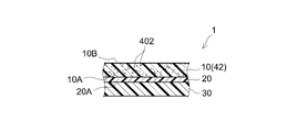
- the pressure-sensitive adhesive film 1 includes a resin film 10 as a base material and a pressure-sensitive adhesive layer 20 provided on one surface (one surface) 10A, and is used by sticking the pressure-sensitive adhesive layer 20 to an adherend.
- the in a preferred embodiment, the back surface (surface opposite to the surface on which the pressure-sensitive adhesive layer 20 is provided) 10B of the resin film 10 is a surface (peeling surface) having releasability.
- the adhesive film 1 before use (that is, before application to the adherend) is wound in a roll shape so that the surface (adhesive surface) 20A of the adhesive layer 20 contacts the back surface 10B of the resin film 10, and this Thus, the surface 20A may be protected.
- the surface 20A of the pressure-sensitive adhesive layer 20 may be protected by a release liner 30 having at least a pressure-sensitive adhesive layer 20 side as a release surface.
- the resin film 10 has a laser light absorption layer 42 provided with a laser light absorber 402.
- the laser light absorption layer 42 is typically a layer made of a resin composition containing the laser light absorber 402.
- the resin film 10 has a single layer structure including the laser light absorption layer 42, but the structure of the resin film 10 is not limited to a single layer structure.
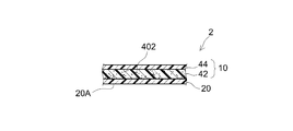
- the resin film 10 has a plurality of layers (here, the first layer 42 disposed on the adhesive layer 20 side and the second layer 44 disposed on the back side thereof).
- the laminated body including at least one of them may be the laser light absorption layer 42.
- the first layer 42 is a layer (laser light absorption layer) made of a resin composition containing the laser light absorber 402, and the second layer 44 is made of a resin composition not containing the laser light absorber. It is a layer.
- the resin film (hereinafter also referred to as “base film”) as a base material in the technology disclosed herein has a laser light absorption rate Amin (1000, 1100) in the wavelength range of 1000 nm to 1100 nm of 20% or more. Characterized by.
- This Amin (1000, 1100) means the ratio of the laser light that is actually absorbed by the base film out of the specific laser light irradiated on the base film. If Amin (1000, 1100) of the base film is less than 20%, the heating efficiency by irradiation with the specific laser light is low, and the base film and the adhesive film including the base film can be appropriately decomposed and lost. Can not. For this reason, the adhesive film cannot be cut, or even if it can be cut temporarily, it is difficult to stably achieve high cutting quality.
- an adhesive film 100 using a resin film 110 that does not contain a laser light absorber and has an Amin (1000, 1001100) smaller than 20% has an adhesive surface 20A of the adhesive film 100 attached to an adherend. Even if it sticks to and irradiates specific laser beam LB from the back, adhesive film 100 of a part corresponding to the irradiation range of laser beam LB cannot fully be heated, and it cannot decompose and disappear. For this reason, the adhesive film 100 cannot be cut by the specific laser beam LB or is cut by melting and deforming the adhesive film 100 mainly due to heat transfer from the adherend even though it can be cut temporarily. As shown in FIG. 5, the accuracy of the shape and cutting width of the cut end face 100E and the irradiation boundary part (near the boundary between the part irradiated with the laser beam and the part not irradiated) 100F cannot be increased.
- the adhesive film 1 provided with the resin film 10 having Amin (1000, 1100) of 20% or more is attached to the adherend, and the specific laser beam LB is irradiated from the back surface.
- the resin film 10 efficiently absorbs the specific laser beam LB and generates heat, the adhesive film 1 can be effectively decomposed and lost and cut. Therefore, the cutting width (width of the gap formed by the laser light irradiation) W of the adhesive film 1 can be accurately controlled according to the irradiation width of the specific laser light LB.
- the adhesive film 1 can be cut with a cutting width W equal to or greater than the irradiation width of the specific laser beam LB.
- disconnection end surface 1E and the irradiation boundary part 1F is realizable.
- the laser light absorber various materials capable of exhibiting an effect of increasing Amin (1000, 1100) can be used alone or in appropriate combination. From the viewpoint of the appearance quality of the cut end face, it is preferable to use a laser light absorbent other than carbon powder (carbon powder).
- Preferred examples of the laser light absorber in the technology disclosed herein include metals and metal compounds. Examples of the metal include aluminum, stainless steel, titanium, nickel, zirconium, tungsten, copper, silver, gold, zinc, molybdenum, chromium, and alloys containing these as main components. Examples of the metal compound include oxides, nitrides and carbides of the above metals. Such metals and metal compounds are typically used in the form of powder and are preferably used as laser light absorbers.
- the laser light absorbent is an organic compound having a property of absorbing a specific laser light.
- organic compounds are, for example, phthalocyanine compounds, cyanine compounds, aminium compounds, naphthalocyanine compounds, naphthoquinone compounds, diimonium compounds, anthraquinone compounds, aromatic dithiol metal complexes (for example, nickel complexes), and the like. obtain.
- the laser light absorption layer includes at least one of the metal powder and the metal compound powder as a laser light absorber.
- a laser beam absorbent is preferable because it can withstand the heat generated by the absorption of the specific laser beam and appropriately maintain the property of absorbing the specific laser beam.
- the technique disclosed here can also be preferably implemented in an embodiment in which the laser light absorption layer does not substantially contain the organic compound as a laser light absorber.
- the laser light absorption layer may further contain the organic compound in addition to one or both of the metal powder and the metal compound powder.
- the technique disclosed herein can be particularly preferably implemented in a mode in which the laser light absorption layer includes at least a metal powder as a laser light absorber.
- Preferred metal powders include aluminum powder, gold powder, silver powder, copper powder, nickel powder, zinc powder and the like. Since such a metal powder has a relatively low hardness, the molding machine is hardly damaged when a resin composition containing the metal powder is formed into a film (film formation). In addition, there is an advantage that a cutting residue due to laser light is hardly generated.
- metal powder made of the same metal as the workpiece can be preferably used as the laser light absorber. .
- the laser light absorption layer substantially does not contain carbon powder (for example, carbon black) as a laser light absorber (for example, the carbon powder content is 0.005% by mass or less, preferably Is preferably zero).
- Carbon powder for example, carbon black
- the carbon powder content is 0.005% by mass or less, preferably Is preferably zero.
- Laser light absorption layers using carbon powder as a laser light absorber tend to have a dark laser cut cross-section or make laser cutting residues more noticeable. is there.
- the shape of the particles constituting the powder is not particularly limited, and may be, for example, a flake shape, a spherical shape, a needle shape, a polyhedral shape, an irregular shape, or the like. obtain.
- a flaky, spherical or acicular laser light absorbent powder can be preferably employed.
- the average particle diameter of such laser light absorber powder is not particularly limited.
- a laser light absorbent powder having an average particle size of 0.01 ⁇ m to 20 ⁇ m (preferably 0.1 ⁇ m to 10 ⁇ m, for example, 0.5 ⁇ m to 5 ⁇ m) can be used.
- a laser light absorber that can be preferably used in the technology disclosed herein is a metal powder (such as flaky aluminum powder) having an average particle size of more than 1 ⁇ m and 5 ⁇ m or less.
- average particle size means, unless otherwise specified, a particle size (50% volume) at an integrated value of 50% in a particle size distribution measured based on a particle size distribution measuring apparatus based on a laser scattering / diffraction method. average particle diameter; hereinafter refers to also) be abbreviated as D 50..
- the laser light absorption rate Amin (1000, 1100) of the base film in the technology disclosed herein is at least 20%, and may be 30% or more.
- the laser light absorption rate Amin (1000, 1100) of the entire adhesive film is also preferably 20% or more (for example, 30% or more). If Amin (1000, 1100) is too low, it becomes difficult to cut the base film (and consequently the adhesive film including the base film) by irradiation with a specific laser beam, or it becomes difficult to achieve high cutting quality.
- Amin (1000, 1100) of the base film may be 100%, but is usually 95% or less.
- the Amin (1000, 1100) of the base film is preferably 80% or less, more preferably 70. % Or less (for example, 60% or less), and may be 50% or less.
- the laser light absorption rate Amin (1000, 1100) of the laser light absorption layer is preferably 20% or more (for example, 30% or more).
- the Amin (1000, 1100) of the laser light absorbing layer is preferably 80% or less (more preferably 70% or less, for example 60% or less), and may be 50% or less.
- the transmittance and reflectance of the base film are not particularly limited as long as the preferable laser light absorption rate Amin (1000, 1100) disclosed herein can be realized.
- a base film having a transmittance T (Amin) of a specific laser beam of less than 50% at a wavelength at which the laser beam absorptivity is minimized (in other words, a wavelength corresponding to Amin (1000, 1100)) Is preferred.
- the base film whose reflectance R (Amin) of the specific laser beam at the wavelength at which the laser beam absorption rate is minimum is less than 50% (more preferably less than 40%) is preferable. This is because a base film satisfying at least one (preferably both) of T (Amin) and R (Amin) is likely to have a preferable laser light absorption rate Amin (1000, 1100) disclosed herein.
- the usage-amount of laser light absorber powder (For example, the mixture ratio of the laser light absorber powder in the resin composition which forms a laser light absorption layer) ) Increases, the transmittance tends to decrease but the reflectance tends to increase (for example, Example 11 and Example 15 described later). Therefore, in consideration of this tendency, the type (material, shape, etc.) and amount of use of the laser light absorber are set so that the preferable laser light absorption rate Amin (1000, 1100) disclosed herein can be realized. It is desirable.
- a base film having a laser light absorption layer made of a resin composition containing a laser light absorber, as a material that can be used as a resin component constituting the resin layer, polyethylene, polypropylene And polyolefin resins such as ethylene-propylene copolymer and polypropylene-polyethylene blend resin; polyester resins such as polyethylene terephthalate and polybutylene terephthalate; and other examples such as vinyl chloride resin, vinyl acetate resin and polyamide resin.
- a resin composition containing a laser light absorbent in such a resin material is typically formed into a film to form a laser light absorbent-containing resin layer.
- the molding method is not particularly limited, and conventionally known extrusion molding methods (for example, inflation extrusion molding method), cast molding methods and the like can be appropriately employed.
- a base film comprising a plurality of resin layers including a laser light absorbent-containing resin layer is a method of simultaneously molding a resin composition corresponding to each resin layer (for example, by a multilayer inflation molding method), and molding each layer. It can be obtained by adopting a method of laminating later, a method of casting another layer on the previously formed layer, alone or in combination.
- the resin component which comprises resin layers other than a laser beam absorber containing resin layer can be suitably employ
- the content ratio of the laser light absorbent (typically powdered laser light absorbent such as metal powder) in the laser light absorbent-containing resin layer can be, for example, 0.01% by mass or more, preferably It is 0.05 mass% or more, More preferably, it is 0.1 mass% or more.
- the laser light absorber-containing resin layer contains a laser light absorber in a proportion exceeding 0.1% by mass.
- the blending ratio of the laser beam absorber in the laser beam absorber-containing resin layer is too large, the reflectance becomes high and a desired laser beam absorption rate is difficult to be realized, or the laser cutting residue is easily noticeable. Can be.
- the blending ratio of the laser beam absorbent in the laser beam absorbent-containing resin layer is 10% by mass or less, preferably 5% by mass or less, more preferably 3% by mass or less (typically Specifically, it is less than 3% by mass). In a preferred embodiment, the blending ratio of the laser beam absorber in the laser beam absorber-containing resin layer is 2% by mass or less (typically less than 2% by mass).
- the laser light absorption layer in the technique disclosed here is not limited to the layer (laser light absorber-containing resin layer) made of the resin composition in which the laser light absorber is blended as described above.
- it may be a layer (laser light absorber layer) made of only the laser light absorber.
- a laser light absorber layer is formed by, for example, vapor deposition, sputtering, coating (for example, applying a dispersion liquid in which a powdered laser light absorber is dispersed in a solvent, removing the solvent, and forming a layer of the laser light dispersant powder. For example).
- the base film in the technology disclosed herein may have a configuration in which a laser light absorbent-containing resin layer is disposed on the surface of a resin layer that does not contain a laser light absorbent, for example, and the laser light absorbent-containing resin
- positioned on the surface of the layer may be sufficient.
- the base film can be blended with any additive as required.
- additives include flame retardants, antistatic agents, colorants (pigments, dyes, etc.), light stabilizers (radical scavengers, ultraviolet absorbers, etc.), antioxidants and the like.
- the surface of the base film may be subjected to an appropriate surface treatment for improving the adhesion to an adjacent material or improving the releasability as necessary.
- the surface treatment for increasing the adhesion include corona discharge treatment, acid treatment, ultraviolet irradiation treatment, plasma treatment, and primer coating (primer) application.
- Such surface treatment can be preferably applied to either one side of the base film (that is, the side on which the pressure-sensitive adhesive layer is provided) and the other side.
- the surface treatment for improving the releasability can be carried out using a general silicone-based, long-chain alkyl-based, fluorine-based release treatment agent or the like.
- Such a surface treatment can be preferably applied to the other surface (back surface) of the base film.
- the thickness of the base film is usually about 10 ⁇ m to 150 ⁇ m. When the thickness is less than 10 ⁇ m, or when the thickness is more than 150 ⁇ m, the handling property of the base film or the pressure-sensitive adhesive film provided with the base film may be easily lowered. In a preferred embodiment, the thickness of the base film is 20 ⁇ m to 110 ⁇ m (more preferably 40 ⁇ m to 100 ⁇ m). In a base film provided with a laser light absorption layer (laser light absorber-containing resin layer) comprising a resin composition containing a laser light absorber, the thickness of the laser light absorption layer is preferably 3 ⁇ m or more. Preferably it is 5 micrometers or more, More preferably, it is 10 micrometers or more.
- the thickness of a laser beam absorption layer (in other words, the location where the laser beam absorber is disposed) is 20% or more (for example, 50% or more) of the entire thickness of the base film, and 70% More preferably (more than 90%).
- the thickness of the laser light absorbing layer is 100% of the total thickness of the base film.
- the pressure-sensitive adhesive constituting the pressure-sensitive adhesive layer in the technology disclosed herein is not particularly limited.
- a known acrylic pressure-sensitive adhesive, rubber-based pressure-sensitive adhesive, polyester-based pressure-sensitive adhesive, polyurethane-based pressure-sensitive adhesive, silicone-based pressure-sensitive adhesive, etc. Can be used. From the viewpoint of adhesive performance and cost, rubber adhesives or acrylic adhesives can be preferably employed.
- the pressure-sensitive adhesive layer may have a single-layer structure or a laminated structure having two or more layers having different compositions.
- alkyl (meth) acrylates such as butyl (meth) acrylate and 2-ethylhexyl (meth) acrylate are the main components and can be copolymerized with the alkyl (meth) acrylate as necessary.
- a polymer having an acrylic polymer having a monomer composition to which a modifying monomer is added as a base polymer (the main component of the polymer components) can be preferably used.
- the modifying monomer examples include hydroxyl group-containing monomers such as 2-hydroxyethyl (meth) acrylate; carboxyl group-containing monomers such as (meth) acrylic acid; styrene monomers such as styrene; vinyl esters such as vinyl acetate And the like.
- hydroxyl group-containing monomers such as 2-hydroxyethyl (meth) acrylate
- carboxyl group-containing monomers such as (meth) acrylic acid
- styrene monomers such as styrene
- vinyl esters such as vinyl acetate And the like.
- Such an acrylic pressure-sensitive adhesive can be obtained by a conventional polymerization method such as a solution polymerization method, an emulsion polymerization method, or an ultraviolet (UV) polymerization method.
- rubber adhesives include natural rubber adhesives and synthetic rubber adhesives.
- specific examples of the rubber-based polymer as the base polymer of the synthetic rubber-based pressure-sensitive adhesive include styrene-based elastomers such as polybutadiene, polyisoprene, butyl rubber, polyisobutylene, and styrene-butadiene-styrene block copolymer; styrene-ethylenebutylene-styrene block Styrenic elastomers such as copolymers, styrene-ethylene butylene random copolymers, and the like; other examples include ethylene propylene rubber, propylene butene rubber, and ethylene propylene butene rubber.
- the above-mentioned pressure-sensitive adhesive layer (in a pressure-sensitive adhesive layer composed of a plurality of layers, at least one of them) can contain a laser light absorber.
- the laser light absorber to be contained in the pressure-sensitive adhesive layer is one kind or two or more kinds from those similar to those exemplified above as the laser light absorbent that can be used in the laser light absorbent-containing resin layer constituting the base film. It can be selected appropriately.
- the content ratio of the laser beam absorber in the pressure-sensitive adhesive layer is suitably 5% by mass or less, and preferably 3% by mass or less (eg, 1% by mass or less). When there is too much content rate of a laser beam absorber, adhesive performance may be impaired.
- the technique disclosed here can be preferably implemented even in an embodiment in which the pressure-sensitive adhesive layer does not substantially contain a laser light absorber.
- any additive may be added to the pressure-sensitive adhesive layer as necessary.
- additives include cross-linking agents, tackifiers, softeners, flame retardants, antistatic agents, colorants (pigments, dyes, etc.), light stabilizers (radical scavengers, UV absorbers, etc.), antioxidants. Agents and the like.
- the thickness of the pressure-sensitive adhesive layer can be appropriately set so as to obtain an appropriate pressure-sensitive adhesive performance according to the use of the pressure-sensitive adhesive film.
- the thickness of the pressure-sensitive adhesive layer is suitably 0.5 ⁇ m to 50 ⁇ m, and preferably 1 ⁇ m to 20 ⁇ m (for example, 2 ⁇ m to 15 ⁇ m).
- the method for providing the pressure-sensitive adhesive layer on the substrate film is not particularly limited.
- a method of directly forming a pressure-sensitive adhesive layer on the surface of a base film by applying a solution obtained by dissolving a pressure-sensitive adhesive layer-forming component dissolved in an organic solvent or a dispersion liquid dispersed in an aqueous solvent to the base film and drying Known methods such as a method of transferring a pressure-sensitive adhesive layer formed on a surface having a base material to a base film, a method of co-extrusion (multi-layer extrusion) of a pressure-sensitive adhesive layer forming component and a resin composition for forming a base film A method can be appropriately employed.
- the pressure-sensitive adhesive film disclosed herein is suitable as a pressure-sensitive adhesive film (laser-cutting pressure-sensitive adhesive film) used by cutting with a laser beam (specific laser light) having a main wavelength of 1000 nm to 1100 nm.
- the time when the pressure-sensitive adhesive film is cut with the specific laser beam may be before being attached to the adherend or after being attached.
- the adhesive film is cut with a specific laser beam before being attached to the adherend, for example, the adhesive film 1 with the surface of the adhesive layer 20 protected by a release liner 30 as shown in FIG.
- a mode in which only the pressure-sensitive adhesive film 1 is cut leaving the release liner 30 by irradiating a specific laser beam from the back surface (back surface 10B of the resin film 10), or a mode in which the pressure-sensitive adhesive film 1 is cut together with the release liner 30 is exemplified.
- the pressure-sensitive adhesive film cut into a desired shape is then attached to an arbitrary adherend, and functions such as surface protection, decoration, display, adhesion to other adherends, etc. Can be achieved.
- the adhesive film is cut with the specific laser light after being attached to the adherend, the adhesive film is attached to the surface of the workpiece, and the laser processing of the workpiece is performed by irradiating the specific laser light from the back surface of the adhesive film.
- a mode of performing (cutting, drilling, cutting, etc.) is exemplified.
- the adhesive film can serve as a protective film that protects the surface of the workpiece before and after laser processing or during laser processing.
- Example 1 In a twin screw extruder (Toshiba Machine Co., Ltd.), 0.13% of flaky aluminum powder with an average particle size of 2 ⁇ m and 99.87% of low density polyethylene (trade name “Petrocene 186R” manufactured by Tosoh Corporation) And granulated at a resin temperature of 180 ° C. to obtain pellets for a substrate. The obtained pellet was formed into a film at a die temperature of 180 ° C. by an inflation molding method to obtain a resin film F1 having a thickness of 90 ⁇ m.
- Example 2 The aluminum powder 0.18% and low-density polyethylene (trade name “Petrocene 186R”, 99.82%, manufactured by Tosoh Corporation) are granulated at a resin temperature of 180 ° C. with the extruder, and pellets for the substrate are obtained. Obtained. The obtained pellet was formed into a film at a die temperature of 180 ° C. by an inflation molding method to obtain a resin film F2 having a thickness of 90 ⁇ m.
- a resin temperature of 180 ° C. trade name “Petrocene 186R”, 99.82%, manufactured by Tosoh Corporation
- Example 3 The aluminum powder 0.25% and low-density polyethylene (trade name “Petrocene 186R” manufactured by Tosoh Corporation) 99.75% are granulated at the resin temperature of 180 ° C. with the extruder, and the pellets for the substrate are formed. Obtained. The obtained pellet was formed into a film at a die temperature of 180 ° C. by an inflation molding method to obtain a resin film F3 having a thickness of 90 ⁇ m.
- a resin film F3 having a thickness of 90 ⁇ m.
- Example 4 The aluminum powder 0.50% and low-density polyethylene (trade name “Petrocene 186R” manufactured by Tosoh Corporation) 99.50% are granulated at a resin temperature of 180 ° C. with the extruder to obtain pellets for a substrate. It was. The obtained pellet was formed into a film at a die temperature of 180 ° C. by an inflation molding method to obtain a resin film F4 having a thickness of 90 ⁇ m.
- Example 5 The aluminum powder 1.50% and low-density polyethylene (trade name “Petrocene 186R” manufactured by Tosoh Corporation) 98.50% are granulated at a resin temperature of 180 ° C. using the extruder, and pellets for a substrate are obtained. Obtained. The obtained pellet was formed into a film at a die temperature of 180 ° C. by an inflation molding method to obtain a resin film F5 having a thickness of 90 ⁇ m.
- Example 6 One side of the resin film F4 produced in Example 4 was subjected to corona discharge treatment.
- the following pressure-sensitive adhesive composition P1 was applied to the corona discharge treated surface so that the thickness after drying was 4 ⁇ m and dried.
- the adhesive film F6 which has an acrylic adhesive layer on the single side
- Adhesive composition P1 A monomer mixture containing 2-ethylhexyl acrylate / vinyl acetate / acrylic acid in a mass ratio of 100/80/5 was polymerized in toluene using benzoyl peroxide (polymerization initiator) to give a weight average molecular weight of 60 ⁇ 10 4 .
- An acrylic polymer was obtained.
- An acrylic pressure-sensitive adhesive composition P1 was prepared by adding 2 parts of an epoxy-based crosslinking agent (trade name “Tetrad C”, manufactured by Mitsubishi Gas Chemical Co., Inc.) to 100 parts of this acrylic polymer.
- Example 7 One side of the resin film F4 produced in Example 4 was subjected to corona discharge treatment.
- the following pressure-sensitive adhesive composition P2 was applied to the corona discharge treated surface so that the thickness after drying was 10 ⁇ m and dried.
- the adhesive film F7 which has a rubber-type adhesive layer on the single side
- Adhesive composition P2 To 100 parts of natural rubber, 70 parts of tackifier (made by Nippon Zeon Co., Ltd., trade name “Quintone A100”), anti-aging agent (made by Ouchi Shinsei Chemical Co., Ltd., trade name “NOCRACK NS-5”) 2 A rubber-based pressure-sensitive adhesive composition P2 was obtained by adding 3 parts of an isocyanate-based crosslinking agent (trade name “Coronate L” manufactured by Nippon Polyurethane Industry Co., Ltd.) and toluene.
- tackifier made by Nippon Zeon Co., Ltd., trade name “Quintone A100”
- anti-aging agent made by Ouchi Shinsei Chemical Co., Ltd., trade name “NOCRACK NS-5”
- a rubber-based pressure-sensitive adhesive composition P2 was obtained by adding 3 parts of an isocyanate-based crosslinking agent (trade name “Coronate L” manufactured by Nippon Polyurethane Industry Co., Ltd.) and to
- Example 8> The aluminum powder 0.60% and random polypropylene (trade name “Prime Polypro F-744NP”, 99.40%, manufactured by Prime Polymer Co., Ltd.) are granulated at a resin temperature of 230 ° C. using the extruder, and the base material Pellets were obtained. The obtained pellet was formed into a film at a die temperature of 230 ° C. by the T-die method to obtain a resin film F8 having a thickness of 40 ⁇ m.
- Example 9 The above aluminum powder 0.60% and polybutylene terephthalate (Mitsubishi Engineering Plastics Co., Ltd., trade name “Novaduran 5505S”) 99.40% are granulated at a resin temperature of 245 ° C. with the above extruder, Pellets were obtained. The obtained pellets were formed into a film at a die temperature of 245 ° C. by the T-die method to obtain a resin film F9 having a thickness of 40 ⁇ m.
- polybutylene terephthalate Mitsubishi Engineering Plastics Co., Ltd., trade name “Novaduran 5505S”
- Low-density polyethylene (trade name “Petrocene 186R” manufactured by Tosoh Corporation) was formed by a blow molding method at a die temperature of 180 ° C. to obtain a resin film having a thickness of 60 ⁇ m.
- One side of this resin film was subjected to corona discharge treatment, and the pressure-sensitive adhesive composition P1 was applied and dried so that the thickness after drying was 4 ⁇ m.
- the adhesive film F10 which has an acrylic adhesive layer on the single side
- Titanium oxide (TiO 2 ) powder having an average particle size of 0.2 ⁇ m (3.00%) and low-density polyethylene (trade name “Petrocene 186R” manufactured by Tosoh Corporation) (97.00%) were added at a resin temperature of 180 using the extruder.
- Granulation was performed at 0 ° C. to obtain pellets for a substrate.
- the obtained pellet was formed into a film at a die temperature of 180 ° C. by an inflation molding method to obtain a resin film having a thickness of 100 ⁇ m.
- One side of this resin film was subjected to corona discharge treatment, and the pressure-sensitive adhesive composition P2 was applied and dried so that the thickness after drying was 10 ⁇ m.
- the adhesive film F11 which has a rubber-type adhesive layer on the single side
- Example 12 The aluminum powder 0.10% and low-density polyethylene (trade name “Petrocene 186R”, 99.90%, manufactured by Tosoh Corporation) are granulated at the resin temperature of 180 ° C. with the extruder, and the pellets for the substrate are obtained. Obtained. The obtained pellet was formed into a film at a die temperature of 180 ° C. by an inflation molding method to obtain a resin film F12 having a thickness of 90 ⁇ m.
- a resin film F12 having a thickness of 90 ⁇ m.
- Random polypropylene (trade name “Prime Polypro F-744NP” manufactured by Prime Polymer Co., Ltd.) was formed at a die temperature of 230 ° C. by the T-die method to obtain a resin film F13 having a thickness of 40 ⁇ m.
- Example 14 Polybutylene terephthalate (manufactured by Mitsubishi Engineering Plastics Co., Ltd., trade name “Novaduran 5505S”) was formed by a T-die method at a die temperature of 245 ° C. to obtain a resin film F14 having a thickness of 40 ⁇ m.
- Example 15 20% of barium sulfate (BaSO 4 ) powder having an average particle size of 0.7 ⁇ m and 80% of polybutylene terephthalate (trade name “Novaduran 5505S”, manufactured by Mitsubishi Engineering Plastics Co., Ltd.) were added at a resin temperature of 245 ° C. using the extruder. To obtain pellets for a substrate. The obtained pellets were formed into a film at a die temperature of 245 ° C. by the T-die method to obtain a resin film F15 having a thickness of 40 ⁇ m.
- BaSO 4 barium sulfate
- polybutylene terephthalate trade name “Novaduran 5505S”, manufactured by Mitsubishi Engineering Plastics Co., Ltd.
- Transmittance measuring device spectrophotometer manufactured by Hitachi High-Technologies Corporation, model “U-4100” Measurement conditions: Measurement mode application measurement, data mode% T, scan speed 750 nm / min, sampling interval 1 nm, slit automatic control, automatic voltage automatic 1, light quantity control mode fixed, high resolution measurement OFF, dimming plate not used, PbS sensitivity 1 , Cell length 10mm Measuring method: (i) The measuring device was turned on and waited for 2 hours or more to stabilize the device. Thereafter, the baseline was measured without setting a sample. (ii).
- a sample is set in the transmittance measurement part of the measuring device (in the case of an adhesive film, set so that light is incident from the back of the adhesive film), and transmitted in the wavelength range of 1000 nm to 1100 nm under the above measurement conditions. The rate was measured.
- Reflectance measuring device spectrophotometer manufactured by Hitachi High-Technologies Corporation, model “U-4100” Measurement conditions: Measurement mode application measurement, data mode% R, scan speed 750 nm / min, sampling interval 1 nm, automatic slit control, automatic voltage control 1, fixed light control mode, high resolution measurement OFF, dimming plate not used, PbS sensitivity 1 , Cell length 10mm Measuring method: (i) The measuring device was turned on and waited for 2 hours or more to stabilize the device. Thereafter, a white standard plate was set on the reflectance measurement portion (no sample was set), and the baseline was measured. (ii). Next, a sample was set in the reflectance measurement portion.
- Laser used YAG laser (wavelength 1064 nm, output 500 W)
- Irradiation conditions Moving speed 10m / min (4-2)
- Laser cutting ii) Each sample (one with a 1 mm thick SUS304 2B plate with an adhesive film pasted, in the case of a resin film with its end fixed with an adhesive tape) is a laser welder (model made by OMRON Laser Front) “M802E” was used.) And was irradiated with laser light along a predetermined cutting line under the following conditions.
- Laser used YAG laser (wavelength 1.06 ⁇ m, output 200 W)
- Irradiation conditions Moving speed 5m / min
- ⁇ The sample (adhesive film only or resin film only) could be cut with a width equal to or greater than the laser irradiation diameter (good laser cutting performance).
- X The sample (adhesive film only or resin film only) could not be cut, or the cutting width was less than the laser irradiation diameter (laser cutting ability was poor).
- the aluminum foil and aluminum film (typically, a continuous film such as a vapor deposition film) have a smooth surface and high reflectance, the above-mentioned specific laser is used.
- aluminum is generally recognized as a reflector.
- the reflectance is suppressed by blending aluminum in powder form (more specifically, flaky powder), and the powdered aluminum is absorbed by laser light. It can be suitably used as an agent. This is supported by the results of Examples 1 to 9 above.
- the said laser beam absorption layer is a resin film as described in said (1) containing at least 1 type selected from a metal powder and a metal compound powder as said laser beam absorber.
- the laser light absorbing layer has the following conditions: A resin composition (for example, a polyolefin resin composition or a polyester resin composition) containing 0.01 to 5% by mass of the laser light absorber; and The laser light absorption rate is 20% or more and 80% or less; The resin film according to (1) or (2), wherein (4) The laser light absorption layer is a resin composition (for example, a polyolefin resin composition or a polyester resin composition) containing 0.01 to 5% by mass of metal powder (for example, aluminum powder) as the laser light absorber.
- a resin composition for example, a polyolefin resin composition or a polyester resin composition
- metal powder for example, aluminum powder
- the resin film according to any one of (1) to (3) comprising: (5) A laser cutting resin film comprising the resin film according to any one of the above (1) to (4) and used by cutting with a laser beam having a main wavelength of 1000 nm to 1100 nm.
- the resin film according to any one of the above (1) to (5) can be suitably used as a base material for any of the pressure-sensitive adhesive films disclosed herein.
- Adhesive film 10 Resin film (base material, base material film) 20: Adhesive layer 30: Release liner 42: Laser light absorption layer (first layer) 100: Adhesive film 110: Resin film (base material, base material film) 120: Substrate (adherend) 402: Laser light absorber LB: Laser light W: Cutting width
Landscapes
- Chemical & Material Sciences (AREA)
- Organic Chemistry (AREA)
- Engineering & Computer Science (AREA)
- Chemical Kinetics & Catalysis (AREA)
- Physics & Mathematics (AREA)
- Optics & Photonics (AREA)
- Plasma & Fusion (AREA)
- Mechanical Engineering (AREA)
- Laminated Bodies (AREA)
- Adhesive Tapes (AREA)
- Adhesives Or Adhesive Processes (AREA)
- Laser Beam Processing (AREA)
Abstract
Description
吸収率A(%)=100(%)-T(%)-R(%) (I)
また、「波長1000nm~1100nmの範囲におけるレーザ光吸収率」とは、当該波長範囲における最小のレーザ光吸収率(以下、「Amin(1000,
1100)」と表すこともある。)を指すものとする。本明細書において「レーザ光吸収剤」とは、当該レーザ光吸収剤を用いない場合に比べてレーザ光吸収率Amin(1000, 1100)を上昇させる作用を発揮し得る材料をいう。
(1)前記レーザ光吸収剤を0.01~5質量%含む樹脂組成物からなる。
(2)前記レーザ光吸収率が20%以上80%以下である。
かかるレーザ光吸収層を有する基材、および該基材を備えた粘着フィルムは、前記特定レーザ光で切断した際に、その切断残渣(典型的には、主としてレーザ光吸収剤に由来する残渣)が周囲(ワーク、レーザ加工に使用する機器、作業環境等)を汚染しにくいので好ましい。前記レーザ光吸収剤としては、一種または二種以上の金属粉末を好ましく使用することができる。なかでもアルミニウム粉末の使用が好ましい。
平均粒径2μmの薄片状アルミニウム粉末0.13%と、低密度ポリエチレン(東ソー株式会社製、商品名「ペトロセン186R」)99.87%とを、2軸押出し機(東芝機械株式会社製)にて樹脂温度180℃で造粒し、基材用ペレットを得た。得られたペレットをインフレーション成形法によりダイス温度180℃で成膜して、厚さ90μmの樹脂フィルムF1を得た。
上記アルミニウム粉末0.18%と低密度ポリエチレン(東ソー株式会社製、商品名「ペトロセン186R」)99.82%とを、上記押出し機にて樹脂温度180℃で造粒し、基材用ペレットを得た。得られたペレットをインフレーション成形法によりダイス温度180℃で成膜して、厚さ90μmの樹脂フィルムF2を得た。
上記アルミニウム粉末0.25%と低密度ポリエチレン(東ソー株式会社製、商品名「ペトロセン186R」)99.75%とを、上記押出し機にて樹脂温度180℃で造粒し、基材用ペレットを得た。得られたペレットをインフレーション成形法によりダイス温度180℃で成膜して、厚さ90μmの樹脂フィルムF3を得た。
上記アルミニウム粉末0.50%と低密度ポリエチレン(東ソー株式会社製、商品名「ペトロセン186R」)99.50%とを、上記押出し機にて樹脂温度180℃で造粒し基材用ペレットを得た。得られたペレットをインフレーション成形法によりダイス温度180℃で成膜して、厚さ90μmの樹脂フィルムF4を得た。
上記アルミニウム粉末1.50%と低密度ポリエチレン(東ソー株式会社製、商品名「ペトロセン186R」)98.50%とを、上記押出し機にて樹脂温度180℃で造粒し、基材用ペレットを得た。得られたペレットをインフレーション成形法によりダイス温度180℃で成膜して、厚さ90μmの樹脂フィルムF5を得た。
例4で作製した樹脂フィルムF4の片面にコロナ放電処理を施した。そのコロナ放電処理面に下記粘着剤組成物P1を、乾燥後の厚みが4μmとなるように塗布して乾燥させた。このようにして、基材の片面にアクリル系粘着剤層を有する粘着フィルムF6を得た。
(粘着剤組成物P1)
2-エチルヘキシルアクリレート/酢酸ビニル/アクリル酸を100/80/5の質量比で含むモノマー混合物を、ベンゾイルパーオキサイド(重合開始剤)を用いてトルエン中で重合させ、重量平均分子量60×104のアクリル系ポリマーを得た。このアクリル系ポリマー100部に対し、エポキシ系架橋剤(三菱瓦斯化学株式会社製、商品名「テトラッドC」)2部を加えて混合したものを、アクリル系粘着剤組成物P1とした。
例4で作製した樹脂フィルムF4の片面にコロナ放電処理を施した。そのコロナ放電処理面に下記粘着剤組成物P2を、乾燥後の厚みが10μmとなるように塗布して乾燥させた。このようにして、基材の片面にゴム系粘着剤層を有する粘着フィルムF7を得た。
(粘着剤組成物P2)
天然ゴム100部に対し、粘着付与剤(日本ゼオン株式会社製、商品名「Quintone A100」)70部、老化防止剤(大内新興化学工業株式会社製、商品名「ノクラックNS-5」)2部、イソシアネート系架橋剤(日本ポリウレタン工業株式会社製、商品名「コロネートL」)3部およびトルエンを加えて混合したものを、ゴム系粘着剤組成物P2とした。
上記アルミニウム粉末0.60%とランダムポリプロピレン(株式会社プライムポリマー製、商品名「プライムポリプロF-744NP」)99.40%とを、上記押出し機にて樹脂温度230℃で造粒し、基材用ペレットを得た。得られたペレットをTダイ法によりダイス温度230℃で成膜して、厚さ40μmの樹脂フィルムF8を得た。
上記アルミニウム粉末0.60%とポリブチレンテレフタレート(三菱エンジニアリングプラスチックス株式会社製、商品名「ノバデュラン5505S」)99.40%とを、上記押出し機にて樹脂温度245℃で造粒し、基材用ペレットを得た。得られたペレットをTダイ法によりダイス温度245℃で成膜して、厚さ40μmの樹脂フィルムF9を得た。
低密度ポリエチレン(東ソー株式会社製、商品名「ペトロセン186R」)をインフレーション成形法によりダイス温度180℃で成膜して、厚さ60μmの樹脂フィルムを得た。この樹脂フィルムの片面にコロナ放電処理を施し、上記粘着剤組成物P1を乾燥後の厚みが4μmとなるように塗布して乾燥させた。このようにして、基材の片面にアクリル系粘着剤層を有する粘着フィルムF10を得た。
平均粒径0.2μmの酸化チタン(TiO2)粉末3.00%と低密度ポリエチレン(東ソー株式会社製、商品名「ペトロセン186R」)97.00%とを、上記押出し機にて樹脂温度180℃で造粒し、基材用ペレットを得た。得られたペレットをインフレーション成形法によりダイス温度180℃で成膜して、厚さ100μmの樹脂フィルムを得た。この樹脂フィルムの片面にコロナ放電処理を施し、上記粘着剤組成物P2を乾燥後の厚みが10μmとなるように塗布して乾燥させた。このようにして、基材の片面にゴム系粘着剤層を有する粘着フィルムF11を得た。
上記アルミニウム粉末0.10%と低密度ポリエチレン(東ソー株式会社製、商品名「ペトロセン186R」)99.90%とを、上記押出し機にて樹脂温度180℃で造粒し、基材用ペレットを得た。得られたペレットをインフレーション成形法によりダイス温度180℃で成膜して、厚さ90μmの樹脂フィルムF12を得た。
ランダムポリプロピレン(株式会社プライムポリマー製、商品名「プライムポリプロF-744NP」)をTダイ法によりダイス温度230℃で成膜して、厚さ40μmの樹脂フィルムF13を得た。
ポリブチレンテレフタレート(三菱エンジニアリングプラスチックス株式会社製、商品名「ノバデュラン5505S」)をTダイ法によりダイス温度245℃で成膜して、厚さ40μmの樹脂フィルムF14を得た。
平均粒径0.7μmの硫酸バリウム(BaSO4)粉末20%とポリブチレンテレフタレート(三菱エンジニアリングプラスチックス株式会社製、商品名「ノバデュラン5505S」)80%とを、上記押出し機にて樹脂温度245℃で造粒し、基材用ペレットを得た。得られたペレットをTダイ法によりダイス温度245℃で成膜して、厚さ40μmの樹脂フィルムF15を得た。
上記で作製した樹脂フィルムまたは粘着フィルムF1~F15から適切なサイズのサンプルを切り出し、以下の項目を評価した。
測定装置:株式会社日立ハイテクノロジーズ製の分光光度計、型式「U-4100」
測定条件:測定モード応用計測、データモード%T、スキャンスピード750nm/min、サンプリング間隔1nm、スリット自動制御、ホトマル電圧自動1、光量制御モード固定、高分解能測定OFF、減光板未使用、PbS感度1、セル長10mm
測定方法:
(i).測定装置の電源を入れ、装置を安定させるために2時間以上待機した。その後、サンプルをセットせずにベースラインを測定した。
(ii).次いで、測定装置の透過率測定部分にサンプルをセット(粘着フィルムの場合は、粘着フィルム背面より入光するようにセット)し、上記測定条件にて1000nm~1100nmの波長範囲の透過率を測定した。
測定装置:株式会社日立ハイテクノロジーズ製の分光光度計、型式「U-4100」
測定条件:測定モード応用計測、データモード%R、スキャンスピード750nm/min、サンプリング間隔1nm、スリット自動制御、ホトマル電圧自動1、光量制御モード固定、高分解能測定OFF、減光板未使用、PbS感度1、セル長10mm
測定方法:
(i).測定装置の電源を入れ、装置を安定させるために2時間以上待機した。その後、反射率測定部分に白色標準板をセットし(サンプルはセットしない。)、ベースラインを測定した。
(ii).次いで、反射率測定部分にサンプルをセットした。このとき、サンプルを透過した光の反射を防止するため、サンプルの入光面と反対側に日東樹脂工業株式会社製の樹脂板、商品名「クラレックス(登録商標)」(黒色、1mm厚)を置いた。サンプルが粘着フィルムの場合には、上記樹脂板に該粘着フィルムを貼り合わせた(貼り合わせ条件:2kgローラー1往復)。そして、上記測定条件にて1000nm~1100nmの波長範囲の反射率を測定した。
上記透過率T(%)および反射率R(%)から、次式:100(%)-T(%)-R(%);により、1000nm~1100nmの波長範囲における最小の吸収率Amin(1000, 1100)を算出した。その結果を、上記最小吸収率の波長における透過率T(Amin)および反射率R(Amin)の値とともに、表1に示す。
(4-1)レーザ切断(i)
各サンプル(1mm厚のSUS304 2B板に粘着フィルムを貼った状態のもの、樹脂フィルムの場合は、その端部を粘着テープで固定した状態のもの)をレーザ溶接機(アマダ社製の型式「YLM-500P」を使用した。)の加工台上にセットし、以下の条件で所定の切断ラインに沿ってレーザ光を照射した。
使用レーザ:YAGレーザ(波長1064nm、出力500W)
照射条件:移動速度10m/min
(4-2)レーザ切断(ii)
各サンプル(1mm厚のSUS304 2B板に粘着フィルムを貼った状態のもの、樹脂フィルムの場合は、その端部を粘着テープで固定した状態のもの)をレーザ溶接機(オムロンレーザーフロント社製の型式「M802E」を使用した。)の加工台上にセットし、以下の条件で所定の切断ラインに沿ってレーザ光を照射した。
使用レーザ:YAGレーザ(波長1.06μm、出力200W)
照射条件:移動速度5m/min
上記レーザ切断(i)およびレーザ切断(ii)の各々について、照射後のサンプルを光学顕微鏡(倍率 100倍)により観察し、以下の2水準でレーザ切断性を評価した。
○:レーザ照射径以上の幅でサンプル(粘着フィルムのみ、または樹脂フィルムのみ)を切断できた(レーザ切断性良)。
×:サンプル(粘着フィルムのみ、または樹脂フィルムのみ)を切断できなかったか、切断幅がレーザ照射径未満であった(レーザ切断性不良)。

なお、アルミニウムは波長1000nm~1100nmのレーザ光を吸収し得るが、アルミニウム箔やアルミニウム膜(典型的には、蒸着膜等の連続膜)は、表面が平滑で反射率が高いため、上記特定レーザ光との関係では、一般にアルミニウムは反射材として認識されている。ここに開示される技術の好ましい一態様によると、アルミニウムを粉末状(より具体的には、薄片状粉末)として樹脂に配合することにより、反射率が抑えられ、該粉末状アルミニウムをレーザ光吸収剤として好適に用いることができる。このことは、上記例1~9の結果によっても裏付けられている。
(1)波長1000nm~1100nmの範囲におけるレーザ光吸収率が20%以上であり、前記レーザ光吸収率を高めるレーザ光吸収剤を備えたレーザ光吸収層を包含する、樹脂フィルム。
(2)前記レーザ光吸収層は、前記レーザ光吸収剤として、金属粉末および金属化合物粉末から選択される少なくとも一種を含む、上記(1)に記載の樹脂フィルム。
(3)前記レーザ光吸収層は、以下の条件:
前記レーザ光吸収剤を0.01~5質量%含む樹脂組成物(例えば、ポリオレフィン樹脂組成物またはポリエステル樹脂組成物)からなる;および、
前記レーザ光吸収率が20%以上80%以下である;
を満たす、上記(1)または(2)に記載の樹脂フィルム。
(4)前記レーザ光吸収層は、前記レーザ光吸収剤として0.01~5質量%の金属粉末(例えば、アルミニウム粉末)を含む樹脂組成物(例えば、ポリオレフィン樹脂組成物またはポリエステル樹脂組成物)からなる、上記(1)~(3)のいずれかに記載の樹脂フィルム。
(5)上記(1)~(4)のいずれかに記載の樹脂フィルムからなり、主波長1000nm~1100nmのレーザ光で切断して用いられる、レーザ切断用樹脂フィルム。
上記(1)~(5)のいずれかに係る樹脂フィルムは、ここに開示されるいずれかの粘着フィルムの基材として好適に利用され得る。
10:樹脂フィルム(基材、基材フィルム)
20:粘着剤層
30:剥離ライナー
42:レーザ光吸収層(第一層)
100:粘着フィルム
110:樹脂フィルム(基材、基材フィルム)
120:基板(被着体)
402:レーザ光吸収剤
LB:レーザ光
W:切断幅
Claims (6)
- 基材としての樹脂フィルムと、該樹脂フィルムの少なくとも一方の面に設けられた粘着剤層とを備え、
前記基材は、波長1000nm~1100nmの範囲におけるレーザ光吸収率が20%以上であり、
前記基材は、前記レーザ光吸収率を高めるレーザ光吸収剤を備えたレーザ光吸収層を包含する、粘着フィルム。 - 前記レーザ光吸収層は、前記レーザ光吸収剤として、金属粉末および金属化合物粉末から選択される少なくとも一種を含む、請求項1に記載の粘着フィルム。
- 前記レーザ光吸収層は、以下の条件:
前記レーザ光吸収剤を0.01~5質量%含む樹脂組成物からなる;および、
前記レーザ光吸収率が20%以上80%以下である;
を満たす、請求項1または2に記載の粘着フィルム。 - 前記樹脂組成物は、ポリオレフィン樹脂組成物またはポリエステル樹脂組成物である、請求項3に記載の粘着フィルム。
- 前記レーザ光吸収層は、前記レーザ光吸収剤として0.01~5質量%の金属粉末を含む樹脂組成物からなる、請求項1から4のいずれか一項に記載の粘着フィルム。
- 請求項1から5のいずれか一項に記載の粘着フィルムからなり、主波長1000nm~1100nmのレーザ光で切断して用いられる、レーザ切断用粘着フィルム。
Priority Applications (5)
| Application Number | Priority Date | Filing Date | Title |
|---|---|---|---|
| CN201280028259.6A CN103608419B (zh) | 2011-06-17 | 2012-05-21 | 粘合薄膜 |
| CA2839610A CA2839610A1 (en) | 2011-06-17 | 2012-05-21 | Pressure-sensitive adhesive film |
| BR112013030920A BR112013030920A2 (pt) | 2011-06-17 | 2012-05-21 | película adesiva sensível à pressão |
| US14/126,696 US20140113131A1 (en) | 2011-06-17 | 2012-05-21 | Pressure-sensitive adhesive film |
| EP12801249.9A EP2722376A4 (en) | 2011-06-17 | 2012-05-21 | ADHESIVE FILM |
Applications Claiming Priority (4)
| Application Number | Priority Date | Filing Date | Title |
|---|---|---|---|
| JP2011-135135 | 2011-06-17 | ||
| JP2011135135 | 2011-06-17 | ||
| JP2012-114796 | 2012-05-18 | ||
| JP2012114796A JP6009812B2 (ja) | 2011-06-17 | 2012-05-18 | 粘着フィルム |
Publications (1)
| Publication Number | Publication Date |
|---|---|
| WO2012172932A1 true WO2012172932A1 (ja) | 2012-12-20 |
Family
ID=47356926
Family Applications (1)
| Application Number | Title | Priority Date | Filing Date |
|---|---|---|---|
| PCT/JP2012/062951 Ceased WO2012172932A1 (ja) | 2011-06-17 | 2012-05-21 | 粘着フィルム |
Country Status (7)
| Country | Link |
|---|---|
| US (1) | US20140113131A1 (ja) |
| EP (1) | EP2722376A4 (ja) |
| JP (1) | JP6009812B2 (ja) |
| CN (1) | CN103608419B (ja) |
| BR (1) | BR112013030920A2 (ja) |
| CA (1) | CA2839610A1 (ja) |
| WO (1) | WO2012172932A1 (ja) |
Families Citing this family (19)
| Publication number | Priority date | Publication date | Assignee | Title |
|---|---|---|---|---|
| EP3205751B1 (en) * | 2014-10-06 | 2024-08-28 | Nitto Denko Corporation | Masking sheet for anodizing |
| EP3012288A1 (en) * | 2014-10-21 | 2016-04-27 | Nitto Denko Corporation | Pressure-sensitive adhesive film for laser beam cutting applications |
| CN104592618B (zh) * | 2015-02-12 | 2017-10-17 | 四川大学 | 一种色变助剂组合物及其制备方法与应用 |
| EP3072879A1 (en) | 2015-03-26 | 2016-09-28 | Nitto Europe N.V | Method for prevention of premature polymerization |
| CN104741796B (zh) * | 2015-04-20 | 2016-05-04 | 京东方科技集团股份有限公司 | 一种液晶显示面板、其制作方法及显示装置 |
| JP2017087475A (ja) * | 2015-11-05 | 2017-05-25 | セイコーエプソン株式会社 | ラベル生成装置、ラベル、及びラベル生成方法 |
| US10759023B2 (en) | 2015-12-30 | 2020-09-01 | 3M Innovative Properties Company | Abrasive articles and related methods |
| WO2017117356A1 (en) | 2015-12-30 | 2017-07-06 | 3M Innovative Properties Company | Abrasive article |
| EP3397490A1 (en) * | 2015-12-30 | 2018-11-07 | 3M Innovative Properties Company | Infrared absorbing adhesive films and related methods |
| US11845885B2 (en) | 2015-12-30 | 2023-12-19 | 3M Innovative Properties Company | Dual stage structural bonding adhesive |
| JP6844180B2 (ja) * | 2016-09-30 | 2021-03-17 | 日本ゼオン株式会社 | 複合パネル及びその製造方法 |
| CN106799548B (zh) * | 2017-02-06 | 2019-04-26 | 京东方科技集团股份有限公司 | 保护膜、激光切割的方法 |
| JP7105222B2 (ja) * | 2017-03-03 | 2022-07-22 | 日東電工株式会社 | 粘着フィルム |
| JP7058096B2 (ja) | 2017-09-27 | 2022-04-21 | 日東電工株式会社 | 粘着フィルム |
| JP7147156B2 (ja) * | 2017-11-29 | 2022-10-05 | 三菱ケミカル株式会社 | レーザー加工用離型フィルム及びレーザー加工品の製造方法 |
| US11171385B2 (en) * | 2018-07-12 | 2021-11-09 | GM Global Technology Operations LLC | Method of forming a separator for a lithium-ion battery |
| KR102733241B1 (ko) * | 2019-05-07 | 2024-11-22 | 삼성디스플레이 주식회사 | 결합 부재, 표시 모듈 및 표시 장치의 제조 방법 |
| CN115706197A (zh) * | 2021-08-12 | 2023-02-17 | 重庆康佳光电技术研究院有限公司 | 激光防护材料及制作方法、发光芯片转移方法和显示面板 |
| CN115746736B (zh) * | 2022-12-08 | 2024-10-29 | 湖北航天化学新材料科技有限公司 | 一种用于光学镜片激光切割的保护膜及制备方法 |
Citations (4)
| Publication number | Priority date | Publication date | Assignee | Title |
|---|---|---|---|---|
| JP2002343747A (ja) * | 2001-05-17 | 2002-11-29 | Lintec Corp | ダイシングシート及びダイシング方法 |
| JP2004064040A (ja) * | 2002-06-03 | 2004-02-26 | Three M Innovative Properties Co | 被研削基材を含む積層体、その製造方法並びに積層体を用いた極薄基材の製造方法及びそのための装置 |
| JP2004235194A (ja) | 2003-01-28 | 2004-08-19 | Mitsubishi Gas Chem Co Inc | 炭酸ガスレーザーによる孔あけ用補助シート |
| JP2006175509A (ja) * | 2004-12-24 | 2006-07-06 | Nitto Denko Corp | レーザー加工用保護シート |
Family Cites Families (3)
| Publication number | Priority date | Publication date | Assignee | Title |
|---|---|---|---|---|
| JP3766468B2 (ja) * | 1996-04-18 | 2006-04-12 | 麒麟麦酒株式会社 | レーザ印字用媒体 |
| ES2279183T3 (es) * | 2002-12-04 | 2007-08-16 | Dsm Ip Assets B.V. | Aditivo absorbedor de luz laser. |
| JPWO2010082514A1 (ja) * | 2009-01-16 | 2012-07-05 | 東レフィルム加工株式会社 | 電磁波シールド性前面フィルターのアース電極取り出し用導電性部材並びにそれを用いた構成体及びディスプレイ |
-
2012
- 2012-05-18 JP JP2012114796A patent/JP6009812B2/ja active Active
- 2012-05-21 US US14/126,696 patent/US20140113131A1/en not_active Abandoned
- 2012-05-21 EP EP12801249.9A patent/EP2722376A4/en not_active Withdrawn
- 2012-05-21 CA CA2839610A patent/CA2839610A1/en not_active Abandoned
- 2012-05-21 WO PCT/JP2012/062951 patent/WO2012172932A1/ja not_active Ceased
- 2012-05-21 BR BR112013030920A patent/BR112013030920A2/pt not_active Application Discontinuation
- 2012-05-21 CN CN201280028259.6A patent/CN103608419B/zh not_active Expired - Fee Related
Patent Citations (4)
| Publication number | Priority date | Publication date | Assignee | Title |
|---|---|---|---|---|
| JP2002343747A (ja) * | 2001-05-17 | 2002-11-29 | Lintec Corp | ダイシングシート及びダイシング方法 |
| JP2004064040A (ja) * | 2002-06-03 | 2004-02-26 | Three M Innovative Properties Co | 被研削基材を含む積層体、その製造方法並びに積層体を用いた極薄基材の製造方法及びそのための装置 |
| JP2004235194A (ja) | 2003-01-28 | 2004-08-19 | Mitsubishi Gas Chem Co Inc | 炭酸ガスレーザーによる孔あけ用補助シート |
| JP2006175509A (ja) * | 2004-12-24 | 2006-07-06 | Nitto Denko Corp | レーザー加工用保護シート |
Non-Patent Citations (1)
| Title |
|---|
| See also references of EP2722376A4 |
Also Published As
| Publication number | Publication date |
|---|---|
| EP2722376A4 (en) | 2015-03-11 |
| CN103608419A (zh) | 2014-02-26 |
| JP6009812B2 (ja) | 2016-10-19 |
| CA2839610A1 (en) | 2012-12-20 |
| US20140113131A1 (en) | 2014-04-24 |
| JP2013018963A (ja) | 2013-01-31 |
| CN103608419B (zh) | 2015-04-22 |
| BR112013030920A2 (pt) | 2016-12-06 |
| EP2722376A1 (en) | 2014-04-23 |
Similar Documents
| Publication | Publication Date | Title |
|---|---|---|
| JP6009812B2 (ja) | 粘着フィルム | |
| WO2012172934A1 (ja) | 粘着フィルム | |
| JP6075978B2 (ja) | 粘着フィルム | |
| JP2016104851A (ja) | レーザ切断用粘着フィルム | |
| CN111108165B (zh) | 粘合薄膜 | |
| JP2019173004A (ja) | 粘着シート、それを用いた導電部材積層体、及び、画像表示装置 | |
| JP2003158098A (ja) | ウェハダイシングテープ用基材 | |
| WO2005090505A1 (ja) | 粘着材、粘着フィルム及びその使用方法 | |
| WO2011108442A1 (ja) | 粘着シート | |
| JP2019163369A (ja) | 粘着シートおよびその利用 | |
| WO2015190230A1 (ja) | ダイシングシート | |
| WO2009119515A1 (ja) | 粘着シート | |
| JP2008273085A (ja) | 表面保護フィルム | |
| WO2011096350A1 (ja) | 表面保護フィルム | |
| JP6953909B2 (ja) | 化粧シートおよび化粧板 | |
| JP5544835B2 (ja) | 表面保護フィルム | |
| JP2010229377A (ja) | 表面保護フィルム | |
| JPWO2010100978A1 (ja) | 粘着シート | |
| JP7558661B2 (ja) | 粘着シート | |
| WO2021187135A1 (ja) | 粘着フィルム | |
| JP2008213297A (ja) | 表面保護フィルム | |
| WO2025018214A1 (ja) | 粘着シート | |
| JP2006198800A (ja) | 保護フィルム付き帯電防止樹脂シート | |
| JP2007050647A (ja) | 複合シート |
Legal Events
| Date | Code | Title | Description |
|---|---|---|---|
| 121 | Ep: the epo has been informed by wipo that ep was designated in this application |
Ref document number: 12801249 Country of ref document: EP Kind code of ref document: A1 |
|
| ENP | Entry into the national phase |
Ref document number: 2839610 Country of ref document: CA |
|
| NENP | Non-entry into the national phase |
Ref country code: DE |
|
| WWE | Wipo information: entry into national phase |
Ref document number: 14126696 Country of ref document: US |
|
| WWE | Wipo information: entry into national phase |
Ref document number: 2012801249 Country of ref document: EP |
|
| REG | Reference to national code |
Ref country code: BR Ref legal event code: B01A Ref document number: 112013030920 Country of ref document: BR |
|
| ENP | Entry into the national phase |
Ref document number: 112013030920 Country of ref document: BR Kind code of ref document: A2 Effective date: 20131129 |