WO2012172954A1 - Dispositif d'étanchéité pour palier d'essieu - Google Patents
Dispositif d'étanchéité pour palier d'essieu Download PDFInfo
- Publication number
- WO2012172954A1 WO2012172954A1 PCT/JP2012/063474 JP2012063474W WO2012172954A1 WO 2012172954 A1 WO2012172954 A1 WO 2012172954A1 JP 2012063474 W JP2012063474 W JP 2012063474W WO 2012172954 A1 WO2012172954 A1 WO 2012172954A1
- Authority
- WO
- WIPO (PCT)
- Prior art keywords
- lubricant
- experiment
- torque
- sealing device
- thickener
- Prior art date
- Legal status (The legal status is an assumption and is not a legal conclusion. Google has not performed a legal analysis and makes no representation as to the accuracy of the status listed.)
- Ceased
Links
Images


Classifications
-
- F—MECHANICAL ENGINEERING; LIGHTING; HEATING; WEAPONS; BLASTING
- F16—ENGINEERING ELEMENTS AND UNITS; GENERAL MEASURES FOR PRODUCING AND MAINTAINING EFFECTIVE FUNCTIONING OF MACHINES OR INSTALLATIONS; THERMAL INSULATION IN GENERAL
- F16C—SHAFTS; FLEXIBLE SHAFTS; ELEMENTS OR CRANKSHAFT MECHANISMS; ROTARY BODIES OTHER THAN GEARING ELEMENTS; BEARINGS
- F16C33/00—Parts of bearings; Special methods for making bearings or parts thereof
- F16C33/30—Parts of ball or roller bearings
- F16C33/66—Special parts or details in view of lubrication
- F16C33/6637—Special parts or details in view of lubrication with liquid lubricant
- F16C33/6681—Details of distribution or circulation inside the bearing, e.g. grooves on the cage or passages in the rolling elements
-
- F—MECHANICAL ENGINEERING; LIGHTING; HEATING; WEAPONS; BLASTING
- F16—ENGINEERING ELEMENTS AND UNITS; GENERAL MEASURES FOR PRODUCING AND MAINTAINING EFFECTIVE FUNCTIONING OF MACHINES OR INSTALLATIONS; THERMAL INSULATION IN GENERAL
- F16C—SHAFTS; FLEXIBLE SHAFTS; ELEMENTS OR CRANKSHAFT MECHANISMS; ROTARY BODIES OTHER THAN GEARING ELEMENTS; BEARINGS
- F16C33/00—Parts of bearings; Special methods for making bearings or parts thereof
- F16C33/72—Sealings
- F16C33/76—Sealings of ball or roller bearings
- F16C33/78—Sealings of ball or roller bearings with a diaphragm, disc, or ring, with or without resilient members
- F16C33/784—Sealings of ball or roller bearings with a diaphragm, disc, or ring, with or without resilient members mounted to a groove in the inner surface of the outer race and extending toward the inner race
- F16C33/7859—Sealings of ball or roller bearings with a diaphragm, disc, or ring, with or without resilient members mounted to a groove in the inner surface of the outer race and extending toward the inner race with a further sealing element
- F16C33/7863—Sealings of ball or roller bearings with a diaphragm, disc, or ring, with or without resilient members mounted to a groove in the inner surface of the outer race and extending toward the inner race with a further sealing element mounted to the inner race, e.g. a flinger to use centrifugal effect
-
- F—MECHANICAL ENGINEERING; LIGHTING; HEATING; WEAPONS; BLASTING
- F16—ENGINEERING ELEMENTS AND UNITS; GENERAL MEASURES FOR PRODUCING AND MAINTAINING EFFECTIVE FUNCTIONING OF MACHINES OR INSTALLATIONS; THERMAL INSULATION IN GENERAL
- F16C—SHAFTS; FLEXIBLE SHAFTS; ELEMENTS OR CRANKSHAFT MECHANISMS; ROTARY BODIES OTHER THAN GEARING ELEMENTS; BEARINGS
- F16C33/00—Parts of bearings; Special methods for making bearings or parts thereof
- F16C33/72—Sealings
- F16C33/76—Sealings of ball or roller bearings
- F16C33/78—Sealings of ball or roller bearings with a diaphragm, disc, or ring, with or without resilient members
- F16C33/7869—Sealings of ball or roller bearings with a diaphragm, disc, or ring, with or without resilient members mounted with a cylindrical portion to the inner surface of the outer race and having a radial portion extending inward
- F16C33/7879—Sealings of ball or roller bearings with a diaphragm, disc, or ring, with or without resilient members mounted with a cylindrical portion to the inner surface of the outer race and having a radial portion extending inward with a further sealing ring
- F16C33/7883—Sealings of ball or roller bearings with a diaphragm, disc, or ring, with or without resilient members mounted with a cylindrical portion to the inner surface of the outer race and having a radial portion extending inward with a further sealing ring mounted to the inner race and of generally L-shape, the two sealing rings defining a sealing with box-shaped cross-section
-
- F—MECHANICAL ENGINEERING; LIGHTING; HEATING; WEAPONS; BLASTING
- F16—ENGINEERING ELEMENTS AND UNITS; GENERAL MEASURES FOR PRODUCING AND MAINTAINING EFFECTIVE FUNCTIONING OF MACHINES OR INSTALLATIONS; THERMAL INSULATION IN GENERAL
- F16J—PISTONS; CYLINDERS; SEALINGS
- F16J15/00—Sealings
- F16J15/16—Sealings between relatively-moving surfaces
- F16J15/32—Sealings between relatively-moving surfaces with elastic sealings, e.g. O-rings
- F16J15/3248—Sealings between relatively-moving surfaces with elastic sealings, e.g. O-rings provided with casings or supports
- F16J15/3252—Sealings between relatively-moving surfaces with elastic sealings, e.g. O-rings provided with casings or supports with rigid casings or supports
- F16J15/3256—Sealings between relatively-moving surfaces with elastic sealings, e.g. O-rings provided with casings or supports with rigid casings or supports comprising two casing or support elements, one attached to each surface, e.g. cartridge or cassette seals
- F16J15/3264—Sealings between relatively-moving surfaces with elastic sealings, e.g. O-rings provided with casings or supports with rigid casings or supports comprising two casing or support elements, one attached to each surface, e.g. cartridge or cassette seals the elements being separable from each other
-
- F—MECHANICAL ENGINEERING; LIGHTING; HEATING; WEAPONS; BLASTING
- F16—ENGINEERING ELEMENTS AND UNITS; GENERAL MEASURES FOR PRODUCING AND MAINTAINING EFFECTIVE FUNCTIONING OF MACHINES OR INSTALLATIONS; THERMAL INSULATION IN GENERAL
- F16C—SHAFTS; FLEXIBLE SHAFTS; ELEMENTS OR CRANKSHAFT MECHANISMS; ROTARY BODIES OTHER THAN GEARING ELEMENTS; BEARINGS
- F16C2233/00—Monitoring condition, e.g. temperature, load, vibration
Definitions
- the present invention relates to a bearing sealing device provided between an inner ring and an outer ring so that a lubricant filled in the bearing does not leak.
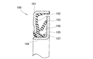
- Patent Document 1 The bearing sealing device disclosed in Patent Document 1 is shown as a cross-sectional view in FIG.
- the bearing sealing device 100 includes a seal member 102 reinforced by a core metal 101, and a slinger 105 slidably contacting lip portions 103 and 104 provided on the seal member 102.
- the slinger 105 has an L-shaped cross section, and a hard chromium plating layer 107 is attached to the sliding contact surface 106.
- Patent Document 2 the hard chrome plating layer 107 shown in FIG. 20 is replaced with DLC (diamond-like carbon). Diamond is hard. Carbon is highly self-lubricating. Therefore, DLC is hard and excellent in lubricity.
- DLC diamond-like carbon
- An object of the present invention is to provide a bearing sealing device in which a lubricant is held on a sliding contact surface, and an increase in torque due to running out of grease can be suppressed.
- the inner ring and the outer ring are prevented from leaking out the lubricant.
- a sealing device for a bearing provided between the seal member and a seal member reinforced with a cored bar, and a slinger having an L-shaped cross section and slidably contacting a lip portion provided on the seal member.
- a bearing sealing device in which a lubricant adsorbing layer comprising a grease thickener and a binder is attached to at least one of the sliding contact surface of the slinger and the lip portion.
- the thickener for grease is lithium stearate or a urea compound
- the binder is alkyd or epoxy
- the thickener for grease is a melamine-based condensate
- the binder is phenol
- the lubricant adsorption layer is formed by a spray method or a dipping method.
- a lubricant adsorbing layer composed of a thickener and a binder is formed on at least one of the sliding surface and the lip portion of the slinger.
- the lubricant filled in the bearing always includes a thickener.
- the thickener contained in the lubricant adsorption layer attracts the thickener in the lubricant.
- the lubricant is adsorbed on the sliding contact surface and / or the lip portion of the slinger provided with the lubricant adsorption layer.
- a bearing sealing device in which a lubricant is held on the sliding contact surface, and an increase in torque due to running out of grease can be suppressed.
- the thickener is lithium stearate or a urea compound. Lithium stearate and urea compounds are easily available, and the lubricant adsorbing layer can be easily attached to the sliding surface and / or lip portion of the slinger.
- the thickener is a melamine condensate.
- a melamine-based condensate has a lower torque and a higher adsorptivity than lithium stearate or a urea compound. When the torque is small, energy loss can be reduced. If the adsorptivity is large, there is no risk of the lubricant running out.
- the lubricant adsorbing layer is formed by a spray method or a dipping method.
- a lubricant adsorbing layer can be provided on the sliding contact surface of the slinger and / or a desired portion of the lip portion.
- the lubricant adsorbing layer can be attached to the sliding surface and / or lip portion of the slinger in a short time, and the production efficiency is increased.
- FIG. 3 is an enlarged cross-sectional view illustrating a relationship between a lip portion, a slinger, and a lubricant adsorbing layer interposed between them shown in FIG. 2. It is an enlarged view in the area
- FIG. 8 is a principle diagram of the test piece friction tester shown in FIG. 7.
- FIG. 6 is a torque curve diagram obtained in Experiments 06 and 08-10. It is a principle figure of the adsorption power test of a lubricant adsorption layer.
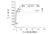
- FIG. 6 is a graph showing the adsorption force curve obtained in Experiments 17-23.
- FIG. 6 is a torque curve diagram obtained in Experiments 17 to 23.
- FIG. 6 is sectional drawing of the sealing device for bearings which showed the example which provided the lubricant adsorption layer in the sealing member.
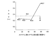
- FIG. 6 is a torque curve diagram obtained in Experiments 24-27.
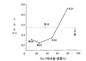
- FIG. 6 is a torque curve diagram obtained in Experiments 28 to 31.
- FIG. 6 is a graph showing the adsorption force curve obtained in Experiments 32-37.
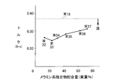
- FIG. 6 is a torque curve diagram obtained in Experiments 32-37.
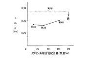
- FIG. 4 is a torque curve diagram obtained in Experiments 38-40. It is sectional drawing of the conventional sealing device for bearings.
- the drive shaft 11 is rotatably supported by the vehicle body frame 10 via a bearing 20.
- the bearing 20 includes an inner ring 21 attached to the drive shaft 11, an outer ring 22 fixed to the body frame 10 with bolts 12, and a plurality of rolling elements 23 provided between the inner ring 21 and the outer ring 22.
- the wheel is fixed to the inner ring 21 with a bolt 24.
- the inner ring 21 is rotated by the drive shaft 11, and the wheel is rotated via the bolt 24.
- a lubricant 25 such as grease is filled around the rolling elements 23.
- a bearing sealing device 30 is provided between the inner ring 21 and the outer ring 22 so that the lubricant 25 does not leak.
- the bearing sealing device 30 includes a seal member 32 reinforced by a cored bar 31 having an L-shaped cross section, and a slinger 34 slidably contacting a lip portion 33 provided on the seal member 32. Become. The slinger 34 is fitted to the inner ring 21, and the cored bar 31 is fitted to the outer ring 22.
- an encoder ring 35 is attached to the outer surface of the slinger 34.
- the encoder ring 35 is a magnet ring in which N poles and S poles are alternately arranged.
- the slinger 34 is a L-shaped member having a cylindrical portion 37 and a disk portion 38 extending radially outward from one end of the cylindrical portion 37, and is obtained by press bending a stainless steel or a plain steel material. .
- An outer peripheral surface of the cylindrical portion 37 and an inner surface of the disc portion 38 serve as a sliding contact surface 39, and a lubricant adsorption layer 40 is attached to the sliding contact surface 39.
- the manufacturing method of the lubricant adsorbing layer 40 will be described later.
- the lubricant adsorbing layer 40 is composed of a thickener for grease (hereinafter simply referred to as a thickener) and a binder. Details of the thickener will be described later.
- the lubricant adsorption layer 40 is formed on the sliding contact surface 39 of the slinger 34.
- the lip portion 33 is a member that seals the lubricant 25, the lubricant 25 exists around the lip portion 33.
- Lubricating oil is liquid and fluidizes. A semi-fluid is formed by mixing a thickener with this lubricating oil.
- the lubricant 25 is a semi-solid material composed of base oil and thickener.
- the lubricant adsorbing layer 40 includes a first thickener 41 and a binder 42.
- the lubricant 25 is composed of the base oil 43 and the thickener 41B as described above. From the experimental results described later, it is estimated that the first thickener 41 and the second thickener 41B have a strong interaction.
- a lubricant layer 44 having a certain thickness is formed on the lubricant adsorption layer 40.
- the lubricant layer 44 is in close contact with the lubricant adsorption layer 40 and is difficult to separate from the lubricant adsorption layer 40. This action brings about an effect specific to the present invention.
- the tip end portion (minimum shear layer) of the lip portion 33 is in the lubricant layer 44 and is always lubricated by the lubricant layer 44, so that the friction coefficient becomes small. As the generation of frictional heat is reduced, the generated heat is absorbed and transmitted to the lubricant layer 44. Therefore, the lip portion 33 does not reach a high temperature and thermal degradation is suppressed.
- FIG. 1 One form of the slinger 34 including the lubricant adsorbing layer 40 that exhibits the action as described above is shown in FIG.
- a lubricant adsorbing layer 40 on almost the entire surface, and an encoder ring 35 is attached to the disc portion 38 through a part of the lubricant adsorbing layer 40.
- the manufacturing method of the slinger 34 of such a form is demonstrated based on FIG.
- a slinger 34 is prepared.
- the container 46 is filled with a mixture 47 of a thickener and a binder.
- the slinger 34 is immersed (dipped) in the mixture 47.
- a mixture 47 having a predetermined film thickness adheres to the slinger 34 pulled up from the container 46 as shown in FIG. Since the binder exhibits an adhesive action, the encoder ring 35 can be attached to the disc portion 38.
- a baking process is performed in a baking furnace 48 shown in FIG. By this firing, a lubricant adsorbing layer 40 (FIG. 4) in which the thickener is hardened with a binder is formed. At the same time, the encoder ring 35 is firmly bonded to the slinger 34.
- FIGS. 6 (e) to 6g a general manufacturing method will be described based on FIGS. 6 (e) to 6g. That is, the following procedure is used to attach the encoder ring 35 to the slinger 34 without using the thickener of the present embodiment.
- the container 120 is filled with the adhesive 121, and the slinger 34 is immersed in the adhesive 121.
- Adhesive 121 is attached to the entire circumference of the slinger 34.
- the encoder ring 35 is bonded to the slinger 34 via the adhesive 121.
- the adhesive 121 is dried in a drying furnace 123.
- the torque becomes high.
- the method of this embodiment by mixing the binder and the thickener component for grease, the lubricant is held between the sliding surface of the slinger and the lip portion, and low torque can be realized.
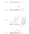
- Test piece production The form of the test piece will be described based on FIG. As shown in FIG. 7A, a test piece 51 having a thickness of 0.6 mm, a SUS (stainless steel) plate having a length of 20 mm and a width of 60 mm subjected to the following pretreatment is prepared. As a pretreatment, a 35 ° C. SUS plate is washed with an organic solvent for 1 minute.
- a test piece 54 is prepared by covering a pre-treated SUS plate 52 with a DLC (diamond-like carbon) layer 53.
- the mixture 47 of the compounding agent and the binder is pumped up by the pump 55 and sent to the nozzle 56 having a nozzle diameter of 0.3 mm.
- the nozzle 56 is separated from the pretreated SUS plate 52 by 50 mm and sprayed at a pressure of 0.1 MPa. This spray is performed twice.
- the compounding agent was any one of PTFE (polytetrafluoroethylene) having a particle diameter of 7 ⁇ m, MoS 2 (molybdenum disulfide) having a particle diameter of 2 ⁇ m, lithium stearate having a particle diameter of 5 ⁇ m, and a urea compound having a particle diameter of 4 ⁇ m.
- the binder was either PAI (polyamideimide), alkyd (alkyd), or epoxy so as to correspond to the compounding agent.
- test piece 57 in which the SUS plate 52 is covered with the lubricant adsorption layer 40 is obtained.
- the test pieces 51, 54, and 57 are subjected to a friction test described below and an adsorption force test described later.
- Friction test As one of the evaluations, a friction test was performed based on a pin-on-plate reciprocating test method (the principle will be described with reference to FIG. 8).
- the pin-on-plate reciprocating test machine 60 includes a machine base 61, a rail 62 laid horizontally on the machine base 61, a slider 63 mounted on the rail 62, and the slider.
- NBR sheet 66 a sheet having a thickness of 3 mm, a length of 5 mm, and a width of 20 mm was used.
- the test piece 51, 54 or 57 is placed on the slider 63, and the lubricant 25 is applied to the test piece 51, 54 or 57.
- the lubricant 25 Nippon Pyronock Universal N6C (product name) (base oil viscosity 113 mm 2 / s) is used.
- the pressing pin 65 is lowered so that the NBR sheet 66 hits the lubricant 25.
- the NBR sheet 66 is pressed against the test piece 51, 54 or 57 by the pressing pin 65 with a surface pressure of 0.2 MPa.
- the test piece 51, 54 or 57 is reciprocated at a speed of 50 mm / sec by the actuator 64.
- the friction coefficient is calculated from the resistance force applied to the actuator 64.
- FIG. 7 (d) that is, PTFE (20% by mass) having a particle diameter of 7 ⁇ m mixed with 80% by mass of PAI as a binder was applied on a SUS plate by spraying, and the friction coefficient was determined. It was measured.
- Experiment 04 the friction coefficient was measured by replacing PTFE having a particle diameter of 7 ⁇ m in Experiment 03 with MoS 2 having a particle diameter of 2 ⁇ m. In both Experiments 03 and 04, the friction coefficient increased.
- Experiment 07 the friction coefficient was measured in the same manner as in Experiment 07 except that the lithium stearate having a particle diameter of 5 ⁇ m in Experiment 06 was replaced with a urea compound having a particle diameter of 4 ⁇ m.
- the coefficient of friction was 0.020, which was smaller than in Experiment 06.
- FIG. 9 shows a principle diagram of the torque tester.
- a variable speed motor 73 in which the motor shaft 72 is vertically arranged so that the motor shaft 72 is in the lower position is attached to the testing machine base 71, and the bearing is provided so that the drive shaft 11 is vertical.
- 20 is prepared, and a testing machine 70 is prepared in which the motor shaft 72 and the drive shaft 11 are connected by a belt 74.
- test machine 70 is provided with a load cell (load meter) 75 as shown in FIG. 9B, and the sensor shaft 76 of the load cell 75 is connected to the outer ring 22.
- load cell load meter
- the outer ring 22 is originally a non-rotating part, it is made rotatable for the experiment, and the rotation is stopped by the sensor shaft 76.
- the bearing 20 used for the torque test was a bearing 20 in which one of the two bearing sealing devices 30 in FIG. 1 was removed, and the first torque was measured with this bearing (with one bearing sealing device).
- Experiment 04a the torque was measured by replacing PTFE having a particle diameter of 7 ⁇ m in Experiment 03 with MoS 2 having a particle diameter of 2 ⁇ m. In both experiments 03a and 04a, the torque increases and the evaluation is x.
- Experiment 07a the torque was measured in the same manner as in Experiment 07a except that the lithium stearate having a particle diameter of 5 ⁇ m in Experiment 06a was replaced with a urea compound having a particle diameter of 4 ⁇ m.
- the torque is 0.205 N ⁇ m, which is greatly reduced to 0.55 times that of Experiment 01a, which is very good. Therefore, the evaluation was ⁇ .
- Experiments 01a to 07a Experiments 01a to 07a, Experiment 06a using a lithium stearate having a particle size of 5 ⁇ m as a compounding agent and Experiment 07a using a urea compound having a particle size of 4 ⁇ m as a compounding agent have good results. It is recommended to use lithium stearate or a urea compound as the agent.
- the torque in Experiment 06 is 0.319 N ⁇ m
- the torque in Experiment 08 is 0.311 N ⁇ m
- the torque in Experiment 09 is 0.319 N ⁇ m
- the torque in Experiment 10 is 0. 563 N ⁇ m.
- the urea compound performs better than lithium stearate. Therefore, the adsorption performance of the urea compound is additionally investigated.
- Adsorption test The adsorption test was performed with a scanning probe microscope (SPM).
- SPM is a microscope that can measure the surface shape, physical properties, etc., of a minute region in a sample using a probe (probe).
- This microscope has modes for measuring mechanical properties such as friction, viscoelasticity, adsorption force, and phase. The suction force is measured using this mode. The principle will be described with reference to FIG.
- the probe includes a cantilever 78 and a sphere 79 attached to the lower surface of the tip of the cantilever 78.
- the sphere 79 is obtained by chemically modifying an amino group on silica beads having a diameter of 20 ⁇ m.
- a lubricant adsorbing layer 40 is attached to the upper surface of the lower SUS plate 52.
- a sphere 79 is applied on the lubricant adsorption layer 40.
- the SUS plate 52 is fixedly held and the cantilever 78 is raised. Then, the sphere 79 is pulled downward, the cantilever 78 is bent, and the reaction force of the cantilever 78 is increased.
- the reaction force (spring force) of the cantilever 78 is superior to the adsorption force, and the sphere 79 is separated from the lubricant adsorption layer 40.
- the adsorption force is obtained from the amount of bending of the cantilever 78 during this period. The results are shown in Table 5.
- the adsorptive power was determined for the same test piece as in Experiment 05 (without compounding agent and with binder).
- the binder does not have an adsorbing action, but rather seems to exert a releasing action.
- the adsorptive power increases as the amount of the urea compound is increased.
- the broken line parallel to the horizontal axis indicates the adsorption force according to Experiment 16.
- Experiment 16 depends on the conditions of no compounding agent and no binder. A larger adsorption force is preferable because the lubricant is retained.
- Experiment 17 is not possible because it is smaller than Experiment 16. Others have larger adsorption power than Experiment 16.
- the preferred compounding amount of the urea compound is 5% by mass or more.
- the torque varies greatly depending on the blending amount of the urea compound.
- the preferred compounding amount of the urea compound is 60% by mass or less. From the viewpoint of both adsorption force and torque, the blending amount of the urea compound is preferably 5 to 60% by mass.
- the lubricant adsorption layer 40 has been attached to the slinger.
- the lubricant adsorption layer 40 can also be provided on the seal member. That is, as shown in FIG. 14, in the bearing sealing device 30 including the metal core 31, the seal member 32, and the slinger 34, the lubricant adsorbing layer 40 can be attached to the seal member 32.
- FIG. 15 is similar to FIG. From this, it was confirmed that the same effect was exhibited regardless of whether the lubricant adsorbing layer was attached to either the sliding surface of the slinger or the lip portion.
- FIG. 16 is similar to FIG. From this, it was confirmed that the same effect was exhibited regardless of whether the lubricant adsorbing layer was attached to either the sliding surface of the slinger or the lip portion.
- lithium stearate or a urea compound can be used as a thickener for grease, and alkyd or epoxy can be used as a binder.
- the adsorption force is shown in the form of a graph in FIG. 17, and the torque is shown in the form of a graph in FIG. As shown in FIG. 17, a convex curve is drawn on the top. The higher the adsorption force, the better the retention of the lubricant. Since the adsorption force in Experiment 16 was 0.082 ⁇ N, all of the adsorption forces obtained in Experiments 32 to 37 exceeded Experiment 16. Furthermore, even if compared with FIG. 12, the attractive force shown in FIG. 17 is remarkably large. This means that the melamine-based condensate can obtain higher adsorption power than lithium stearate and urea compounds.
- the obtained torque is shown in the form of a graph in FIG. As shown in FIG. 19, a downward convex curve is drawn. Since torque leads to energy loss, the smaller the better. Since the torque in Experiment 16 was 0.375 N ⁇ m, all of the torques obtained in Experiment 38 to Experiment 40 were lower than in Experiment 16.
- a melamine-based condensate can be used as a thickener for grease and phenol can be used as a binder.
- the bearing sealing structure is suitable for a vehicle, but may be applied to a general machine other than a vehicle.
- the bearing sealing structure of the present invention is suitable for a vehicle.
Landscapes
- Engineering & Computer Science (AREA)
- General Engineering & Computer Science (AREA)
- Mechanical Engineering (AREA)
- Lubricants (AREA)
- Rolling Contact Bearings (AREA)
- Sealing Of Bearings (AREA)
Abstract
Priority Applications (3)
| Application Number | Priority Date | Filing Date | Title |
|---|---|---|---|
| US14/115,045 US8894289B2 (en) | 2011-06-13 | 2012-05-25 | Sealing device for axle bearing |
| CN201280024231.5A CN103562578B (zh) | 2011-06-13 | 2012-05-25 | 轴承用密封装置 |
| JP2013520491A JP5560374B2 (ja) | 2011-06-13 | 2012-05-25 | 軸受用密封装置 |
Applications Claiming Priority (2)
| Application Number | Priority Date | Filing Date | Title |
|---|---|---|---|
| JP2011-131480 | 2011-06-13 | ||
| JP2011131480 | 2011-06-13 |
Publications (1)
| Publication Number | Publication Date |
|---|---|
| WO2012172954A1 true WO2012172954A1 (fr) | 2012-12-20 |
Family
ID=47356948
Family Applications (1)
| Application Number | Title | Priority Date | Filing Date |
|---|---|---|---|
| PCT/JP2012/063474 Ceased WO2012172954A1 (fr) | 2011-06-13 | 2012-05-25 | Dispositif d'étanchéité pour palier d'essieu |
Country Status (4)
| Country | Link |
|---|---|
| US (1) | US8894289B2 (fr) |
| JP (1) | JP5560374B2 (fr) |
| CN (1) | CN103562578B (fr) |
| WO (1) | WO2012172954A1 (fr) |
Families Citing this family (4)
| Publication number | Priority date | Publication date | Assignee | Title |
|---|---|---|---|---|
| CN103946350B (zh) * | 2011-11-23 | 2016-08-17 | Abb研究有限公司 | 密封系统,具有密封系统的工业机器人,以及用于提供密封表面的方法 |
| DE102018101875A1 (de) * | 2018-01-29 | 2019-08-01 | Schaeffler Technologies AG & Co. KG | Radlager, Radlagereinheit und Radaufhängung |
| EP3864324A1 (fr) * | 2018-10-08 | 2021-08-18 | Andrew W. Suman | Joint d'arbre résistant à l'oscillation |
| US20250243938A1 (en) * | 2024-01-26 | 2025-07-31 | Caterpillar Inc. | Coated wear sleeve for dynamic shaft |
Citations (2)
| Publication number | Priority date | Publication date | Assignee | Title |
|---|---|---|---|---|
| JPS6158520B2 (fr) * | 1976-09-27 | 1986-12-11 | Nok Corp | |
| JP2002227856A (ja) * | 2001-01-31 | 2002-08-14 | Koyo Seiko Co Ltd | 車軸用軸受の密封装置 |
Family Cites Families (10)
| Publication number | Priority date | Publication date | Assignee | Title |
|---|---|---|---|---|
| US5290596A (en) * | 1989-12-01 | 1994-03-01 | Glyco-Metall-Werke Glyco B.V. & Co, Kg | Method of making composite laminate for sliding elemens |
| US5997005A (en) * | 1997-10-24 | 1999-12-07 | Stemco Inc | Hub seal with machinable thrust ring |
| IT1303577B1 (it) * | 1998-12-11 | 2000-11-14 | Skf Ind Spa | Dispositivo di tenuta per cuscinetti. |
| JP2003262231A (ja) | 2002-03-08 | 2003-09-19 | Nsk Ltd | 転がり軸受用シール、シール付軸受及びハブユニット軸受 |
| DE16178219T1 (de) * | 2004-12-16 | 2017-03-16 | Uchiyama Manufacturing Corp. | Dichtungsanordnung für ein drehelement |
| EP1913271B1 (fr) * | 2005-08-01 | 2014-03-12 | Ab Skf | Dispositif d'étanchéité et son procédé de fabrication |
| JP2008240960A (ja) * | 2007-03-28 | 2008-10-09 | Jtekt Corp | 転がり軸受 |
| WO2009144785A1 (fr) * | 2008-05-27 | 2009-12-03 | 日本精工株式会社 | Roulement |
| JP5234651B2 (ja) * | 2008-08-29 | 2013-07-10 | 内山工業株式会社 | 密封装置 |
| CN101718303B (zh) * | 2009-12-15 | 2012-01-18 | 山东郓城昊润机械制造有限公司 | 发动机微溶轴瓦 |
-
2012
- 2012-05-25 WO PCT/JP2012/063474 patent/WO2012172954A1/fr not_active Ceased
- 2012-05-25 CN CN201280024231.5A patent/CN103562578B/zh not_active Expired - Fee Related
- 2012-05-25 US US14/115,045 patent/US8894289B2/en active Active
- 2012-05-25 JP JP2013520491A patent/JP5560374B2/ja not_active Expired - Fee Related
Patent Citations (2)
| Publication number | Priority date | Publication date | Assignee | Title |
|---|---|---|---|---|
| JPS6158520B2 (fr) * | 1976-09-27 | 1986-12-11 | Nok Corp | |
| JP2002227856A (ja) * | 2001-01-31 | 2002-08-14 | Koyo Seiko Co Ltd | 車軸用軸受の密封装置 |
Also Published As
| Publication number | Publication date |
|---|---|
| CN103562578A (zh) | 2014-02-05 |
| US20140093200A1 (en) | 2014-04-03 |
| CN103562578B (zh) | 2016-02-10 |
| JPWO2012172954A1 (ja) | 2015-02-23 |
| JP5560374B2 (ja) | 2014-07-23 |
| US8894289B2 (en) | 2014-11-25 |
Similar Documents
| Publication | Publication Date | Title |
|---|---|---|
| JP4897343B2 (ja) | 軸受部材 | |
| JP6417400B2 (ja) | 摺動エンジン部品 | |
| JP5560374B2 (ja) | 軸受用密封装置 | |
| WO2011104939A1 (fr) | Palier coulissant | |
| JPWO2012111774A1 (ja) | 摺動材料組成物及び摺動部材 | |
| JP4993908B2 (ja) | 樹脂組成物、摺動部材及び摺動装置 | |
| JP2013204807A (ja) | すべり軸受 | |
| KR20230124022A (ko) | 구름 베어링 | |
| JP5897961B2 (ja) | すべり軸受 | |
| JP5878062B2 (ja) | すべり軸受 | |
| KR102391002B1 (ko) | 코팅액 및 이를 이용한 자동차 드라이브 샤프트용 와셔 | |
| WO2008069177A1 (fr) | Palier à roulement et palier à élément roulant total | |
| JP2013515624A (ja) | 層状複合材料 | |
| JP2017198325A (ja) | 摺動部材 | |
| EP3434919B1 (fr) | Dispositif de retenue de palier à rouleaux, et palier à rouleaux | |
| JP2008180374A (ja) | 転がり軸受 | |
| Kolour et al. | Polymeric coatings: a game changer for bearings in hybrid and electric automobiles | |
| JP5816121B2 (ja) | すべり軸受とその製造方法 | |
| BR102012014337A2 (pt) | bronzina para motores de combustão interna | |
| EP3615621B1 (fr) | Matériau de palier, palier et procédé | |
| JP2016138563A (ja) | 転動装置 | |
| JP2008259965A (ja) | 表面処理方法および摺動部材 | |
| Stolarski et al. | Tribological performance of PTFE–metal binary coatings in rolling/sliding contact | |
| Krus Jr et al. | ToughMet® alloy: Improving thrust bearing performance through enhanced material properties | |
| JP2007231941A (ja) | 斜板式コンプレッサの斜板および斜板式コンプレッサ |
Legal Events
| Date | Code | Title | Description |
|---|---|---|---|
| 121 | Ep: the epo has been informed by wipo that ep was designated in this application |
Ref document number: 12800415 Country of ref document: EP Kind code of ref document: A1 |
|
| ENP | Entry into the national phase |
Ref document number: 2013520491 Country of ref document: JP Kind code of ref document: A |
|
| WWE | Wipo information: entry into national phase |
Ref document number: 14115045 Country of ref document: US |
|
| NENP | Non-entry into the national phase |
Ref country code: DE |
|
| 122 | Ep: pct application non-entry in european phase |
Ref document number: 12800415 Country of ref document: EP Kind code of ref document: A1 |