WO2012172961A1 - Amortisseur visqueux magnétique - Google Patents
Amortisseur visqueux magnétique Download PDFInfo
- Publication number
- WO2012172961A1 WO2012172961A1 PCT/JP2012/063708 JP2012063708W WO2012172961A1 WO 2012172961 A1 WO2012172961 A1 WO 2012172961A1 JP 2012063708 W JP2012063708 W JP 2012063708W WO 2012172961 A1 WO2012172961 A1 WO 2012172961A1
- Authority
- WO
- WIPO (PCT)
- Prior art keywords
- cylinder
- magnetorheological fluid
- piston
- magnetic
- shock absorber
- Prior art date
- Legal status (The legal status is an assumption and is not a legal conclusion. Google has not performed a legal analysis and makes no representation as to the accuracy of the status listed.)
- Ceased
Links
Images

Classifications
-
- F—MECHANICAL ENGINEERING; LIGHTING; HEATING; WEAPONS; BLASTING
- F16—ENGINEERING ELEMENTS AND UNITS; GENERAL MEASURES FOR PRODUCING AND MAINTAINING EFFECTIVE FUNCTIONING OF MACHINES OR INSTALLATIONS; THERMAL INSULATION IN GENERAL
- F16F—SPRINGS; SHOCK-ABSORBERS; MEANS FOR DAMPING VIBRATION
- F16F9/00—Springs, vibration-dampers, shock-absorbers, or similarly-constructed movement-dampers using a fluid or the equivalent as damping medium
- F16F9/32—Details
- F16F9/53—Means for adjusting damping characteristics by varying fluid viscosity, e.g. electromagnetically
- F16F9/535—Magnetorheological [MR] fluid dampers
Definitions
- the present invention relates to a magnetorheological fluid shock absorber using a magnetorheological fluid whose apparent viscosity changes due to the action of a magnetic field.
- Some shock absorbers mounted on vehicles such as automobiles change the damping force by applying a magnetic field to the flow path through which the magnetorheological fluid passes to change the apparent viscosity of the magnetorheological fluid.
- JP 2007-239982A discloses a magnetorheological fluid damper in which permanent magnets are attached to both axial ends of a cylinder in which magnetorheological fluid is sealed.
- a magnetorheological fluid damper In this magnetorheological fluid damper, a yoke material is provided on the outer periphery of a cylinder, and a piston and a part of the piston rod are formed of a ferromagnetic material.
- the magnetic force of the permanent magnet does not act on the magnetorheological fluid.
- the piston strokes beyond the neutral region a magnetic circuit is formed from the permanent magnet through the piston rod, the piston, and the yoke material. As a result, the magnetic force of the permanent magnet acts on the magnetorheological fluid between the piston and the cylinder, and the viscosity of the magnetorheological fluid increases and the damping coefficient increases.
- the present invention has been made in view of the above problems, and in a magnetorheological fluid shock absorber in which a magnet is attached to a cylinder, magnetism is efficiently applied to continuously reduce the damping coefficient with respect to the stroke amount of the piston.
- the purpose is to change.
- a magnetorheological fluid shock absorber using a magnetorheological fluid whose viscosity is changed by the action of a magnetic field is formed by a nonmagnetic material, and the magnetorheological fluid is enclosed in the inner periphery thereof.
- a piston formed by a cylindrical cylinder and a non-magnetic material and slidably disposed in the cylinder with an interval through which the magnetorheological fluid can pass is connected between the cylinder and the piston.
- a piston rod that is attached to the cylinder and causes a magnetic field to act in the cylinder, and the magnet portion is formed by a permanent magnet having an inner peripheral shape along the outer periphery of the cylinder, and a magnetic body. And a ring member disposed on the outer peripheral side of the permanent magnet.
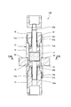
- FIG. 1 is a cross-sectional view of a magnetorheological fluid damper according to a first embodiment of the present invention.
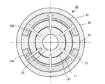
- 2A is a cross-sectional view taken along the line IIA-IIA in FIG.
- FIG. 2B is a diagram illustrating a permanent magnet of the magnetorheological fluid shock absorber according to the first embodiment of the present invention.
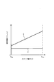
- FIG. 3 is a graph illustrating the operation of the magnetorheological fluid damper according to the first embodiment of the present invention.
- FIG. 4A is a sectional view of a piston, a cylinder, and a magnet part of a magnetorheological fluid shock absorber according to a second embodiment of the present invention.
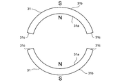
- FIG. 4B is a diagram illustrating a permanent magnet of a magnetorheological fluid shock absorber according to the second embodiment of the present invention.
- FIG. 5A is a cross-sectional view of a piston, a cylinder, and a magnet part of a modification of the magnetorheological fluid damper according to the second embodiment of the present invention.
- FIG. 5B is a diagram illustrating a permanent magnet of a modification of the magnetorheological fluid damper according to the second embodiment of the present invention.
- FIG. 1 is a cross-sectional view of a magnetorheological fluid shock absorber 100.
- the magnetorheological fluid shock absorber 100 is a damper capable of changing a damping coefficient with respect to a force applied in the axial direction by using a magnetorheological fluid whose viscosity is changed by the action of a magnetic field.
- the magnetorheological fluid shock absorber 100 is formed such that the damping coefficient thereof changes in proportion to the stroke amount of the piston 21.
- the magnetorheological fluid shock absorber 100 includes a cylindrical cylinder 10 in which a magnetorheological fluid is sealed on the inner periphery thereof, a piston 21 disposed in the cylinder 10 so as to be slidable in the axial direction of the cylinder 10, and a piston The piston rod 22 to which the reference numeral 21 is connected, and the magnet portion 30 that is fixed to the outer periphery of the cylinder 10 and applies a magnetic field to the cylinder 10.
- the magnetorheological fluid sealed in the cylinder 10 changes its apparent viscosity by the action of a magnetic field, and is a liquid in which fine particles having ferromagnetism are dispersed in a liquid such as oil.
- the viscosity of the magnetorheological fluid changes according to the strength of the applied magnetic field, and becomes the minimum when there is no influence of the magnetic field.
- the cylinder 10 includes a cylindrical portion 11 formed in a cylindrical shape having openings at both ends thereof, and a head member 12 and a bottom member 13 attached to the openings at both ends of the cylindrical portion 11.
- the cylindrical part 11 has a screwing part 11a formed on the inner periphery of one opening part and a screwing part 11b formed on the inner periphery of the other opening part.
- a screwing portion 12b that is screwed with the screwing portion 11a of the cylindrical portion 11 is formed.
- a seal member 14a is provided between the inner periphery of the cylindrical portion 11 and the outer periphery of the head member 12, and the magnetorheological fluid in the cylinder 10 is sealed.
- the head member 12 is formed with a hole 12a through which the piston rod 22 is inserted.
- a screwing portion 13b that is screwed with the screwing portion 11b of the cylindrical portion 11 is formed on the outer periphery of the bottom member 13.
- a seal member 14b is provided between the inner periphery of the cylindrical portion 11 and the outer periphery of the bottom member 13, and the magnetorheological fluid in the cylinder 10 is sealed.
- the bottom member 13 is formed with a hole 13a through which the piston rod 22 is inserted.
- the cylinder 10 is formed of a nonmagnetic material. Accordingly, the cylinder 10 is prevented from becoming a magnetic path, and a magnetic field can be efficiently applied from the magnet unit 30 to the magnetorheological fluid sealed in the cylinder 10.
- the cylinder 10 has an annular recess 15 formed on the outer periphery of the cylindrical portion 11 so as to be thinner than other portions of the cylinder 10.
- a magnet unit 30 is fitted around the recess 15.
- the piston 21 is formed in a columnar shape whose outer diameter is smaller than the inner diameter of the cylindrical portion 11 in the cylinder 10. That is, the piston 21 is formed between the inner periphery of the cylindrical portion 11 in the cylinder 10 with an annular interval through which the magnetorheological fluid can pass.
- the magnetorheological fluid shock absorber 100 When the piston 21 slides in the cylinder 10 in the axial direction, the magnetorheological fluid passes through the space between the piston 21 and the cylinder 10.
- the magnetorheological fluid shock absorber 100 generates a damping force by the annular space between the piston 21 and the cylinder 10 acting as a throttle.
- Piston 21 is formed of a non-magnetic material. Thereby, the magnetic field of the magnet part 30 does not act directly on the piston 21, and it is possible to prevent the piston 21 from being brought to one side and increasing the friction.
- the piston rod 22 is formed so as to be coaxial with the piston 21 and is inserted through the center of the piston 21.
- the piston rod 22 is formed integrally with the piston 21.
- the piston rod 22 may be formed separately from the piston 21 and joined by screws or the like.
- One end 22a of the piston rod 22 is inserted into the hole 12a of the head member 12, is slidably supported by the head member 12, and extends to the outside of the cylinder 10.
- the other end 22 b of the piston rod 22 is inserted into the hole 13 a of the bottom member 13 and is slidably supported by the bottom member 13.
- the piston rod 22 is slidably supported by the head member 12 and the bottom member 13, so that even if there is an annular interval between the outer periphery of the piston 21 and the inner periphery of the cylinder 10, The cylinder 10 can slide in the axial direction without being displaced in the radial direction.
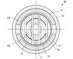
- FIG. 2A is a cross-sectional view taken along the line IIA-IIA in FIG.
- FIG. 2B is a diagram illustrating the permanent magnet 31 of the magnetorheological fluid shock absorber 100 according to the first embodiment of the present invention.
- the magnet part 30 has a circular cross section.
- the magnet unit 30 is fitted around the recess 15 of the cylinder 10.
- the recess 15 is formed thinner than the other part of the cylinder 10. Therefore, it does not prevent the magnetic field of the magnet unit 30 from acting on the magnetorheological fluid sealed in the cylinder 10.
- the magnet unit 30 includes a pair of permanent magnets 31, a support member 33 that supports the permanent magnets 31, and an annular magnetic ring member 32 that is fitted around the permanent magnets 31 and the support member 33.
- the permanent magnet 31 has an inner peripheral surface 31a composed of a partial arc of the first circumference centered on the same axis as the center of the cylinder 10, and the same center as the first circumference. Surrounded by an outer peripheral surface 31b made of a partial arc of a second circumference having a larger diameter than the first circumference, and a pair of side surfaces 31c connecting the inner peripheral face 31a and the outer peripheral face 31b. This is a C-shaped segment magnet having an arc shape.
- the pair of permanent magnets 31 are formed in the same shape and are arranged symmetrically with respect to the central axis of the cylinder 10.
- the permanent magnet 31 has a pair of magnetic poles magnetized in the radial direction.
- the permanent magnets 31 are magnetized so that the inner peripheral surface 31a side is an N pole and the outer peripheral surface 31b side is an S pole.
- the pair of permanent magnets 31 are arranged such that their magnetic poles face each other with respect to the central axis of the cylinder 10. That is, the pair of permanent magnets 31 are magnetized in the same direction and are arranged symmetrically with respect to a line segment passing through the central axis of the cylinder 10.
- the inner peripheral side of the support member 33 is formed in a cylindrical shape along the periphery of the annular recess 15.
- a groove 33a and a groove 33b for fixing the permanent magnet 31 to the outer shape on the circumference are formed on the outer peripheral side of the support member 33.
- the support member 33 forms a circle having the same outer circumference as the second circumference described above in a state where the permanent magnets 31 are fixed to the groove 33a and the groove 33b, respectively.
- the support member 33 is formed of a non-magnetic material in the same manner as the cylinder 10. Thereby, it is prevented that the supporting member 33 becomes a magnetic path, and the magnetic field from the magnet part 30 acts on a magnetorheological fluid efficiently.
- An annular magnetic ring member 32 made of a magnetic material is fitted on the outer periphery of the support member 33.
- the magnetic ring member 32 is fitted in close contact with the outer periphery of the support member 33 in a state where the permanent magnets 31 are fixed to the groove 33a and the groove 33b, respectively.
- the magnetic ring member 32 constitutes a magnetic path of a magnetic field generated by the permanent magnet 31.
- the magnetic ring member 32 is formed of a soft magnetic material having a high magnetic permeability and a small coercivity of the residual magnetic field.
- the pair of permanent magnets 31 are fixed separately from each other by the support member 33. That is, in the permanent magnet 31, the center angle of the inner peripheral surface 31a and the outer peripheral surface 31b is set to be less than 180 °. Further, the outer peripheral surface 31 b of the permanent magnet 31 is in close contact with the inner peripheral surface of the magnetic ring member 32.
- the magnet unit 30 generates a magnetic field in the direction indicated by the arrow in FIG. 2A. That is, by arranging the magnetic poles of the pair of permanent magnets 31 to face each other, a radial magnetic force is generated from the central axis of the cylinder 10. This magnetic force acts evenly on the magnetorheological fluid existing in the interval between the piston 21 and the cylinder 10, and can increase the viscosity of the magnetorheological fluid.
- the magnetic ring member 32 made of a magnetic material is disposed outside the permanent magnet 31, the magnetic field directed toward the outer peripheral surface 31b passes through the inside of the magnetic ring member 32 without being diverged. Thereby, a magnetic field can be made to act on a magnetorheological fluid more efficiently.
- the magnet unit 30 is arranged corresponding to the position of the piston 21 when the piston rod 22 enters the cylinder 10 most. Therefore, the viscosity of the magnetorheological fluid in the cylinder 10 differs depending on the position in the axial direction. Specifically, the magnetic viscous fluid in the cylinder 10 is more affected by the magnetic field as it gets closer to the magnet unit 30, and the viscosity increases due to the collection of ferromagnetic particles. On the other hand, as the magnetorheological fluid in the cylinder 10 moves away from the magnet unit 30, the influence of the magnetic field becomes smaller and the viscosity becomes lower.
- the horizontal axis represents the stroke amount S [m], which is the amount of the piston rod 22 entering the cylinder 10, and the vertical axis represents the damping coefficient C [N ⁇ s / m] of the magnetorheological fluid shock absorber 100. is there.
- a straight line X indicates the damping coefficient C of the magnetorheological fluid shock absorber 100
- a straight line Y indicates the magnetorheological fluid in the cylinder 10 without providing the magnet unit 30 in the magnetorheological fluid shock absorber 100.
- the attenuation coefficient C when no magnetic field acts on is shown.
- the attenuation coefficient C in this case is always a constant value with respect to the change in the stroke amount S as shown by the straight line Y.
- the damping coefficient C is the minimum when the stroke amount in which the piston rod 22 is most retracted from the cylinder 10 is S min as shown by the straight line X.
- the stroke amount is S min
- the magnetorheological fluid in the cylinder 10 is affected by the magnetic field by the magnet unit 30 and the ferromagnetic particles are aligned, so the magnet unit 30 is not provided.
- the damping coefficient C is larger.
- the damping coefficient C of the magnetorheological fluid shock absorber 100 can be increased proportionally.
- the cylinder 10 and the piston 21 are formed of a non-magnetic material, and the cylinder 10 is attached with a magnet unit 30 that applies a magnetic field to the magnetorheological fluid in the cylinder 10. Therefore, the cylinder 10 and the piston 21 do not form a magnetic path, and the influence of the magnetic field on the magnetorheological fluid passing through the interval between the cylinder 10 and the piston 21 is caused by the piston 21 strokes to the magnet unit 30. It will gradually increase as you get closer. Therefore, the damping coefficient can be continuously changed with respect to the stroke amount of the piston 21.
- the magnet unit 30 includes a pair of permanent magnets 31 that are C-shaped segment magnets having an inner peripheral shape along the outer peripheral shape of the cylindrical cylinder 10 in which the magnetorheological fluid is enclosed. Thereby, a magnetic field acts on the magnetorheological fluid which exists in the space
- the magnetic ring member 32 of magnetic material is disposed outside the permanent magnet 31, the magnetic field toward the outer peripheral surface 31b passes through the magnetic ring member 32 without being diverged. Thereby, a magnetic field can be made to act on a magnetorheological fluid efficiently.
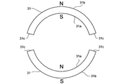
- FIG. 4A is a cross-sectional view of the cylinder 10 and the magnet unit 30 of the magnetorheological fluid shock absorber according to the second embodiment of the present invention
- FIG. 4B illustrates the magnetorheological fluid shock absorber according to the second embodiment of the present invention. It is a figure explaining the permanent magnet 31.
- FIG. FIG. 4A is a cross-sectional view of the cylinder 10 and the magnet unit 30 of the magnetorheological fluid shock absorber according to the second embodiment of the present invention
- FIG. 4B illustrates the magnetorheological fluid shock absorber according to the second embodiment of the present invention. It is a figure explaining the permanent magnet 31.
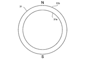
- FIG. 5A is a cross-sectional view of a cylinder 10 and a magnet unit 30 of a modification of the magnetorheological fluid shock absorber according to the second embodiment of the present invention
- FIG. 5B is a magnetic diagram according to the second embodiment of the present invention. It is a figure explaining the permanent magnet 31 of the modification of the viscous fluid shock absorber 100.
- the magnetic viscous fluid shock absorber according to the second embodiment has the same basic configuration as the magnetic viscous fluid shock absorber 100 according to the first embodiment shown in FIG.
- the magnetorheological fluid shock absorber according to the second embodiment is different from the magnetorheological fluid shock absorber 100 according to the first embodiment only in the configuration of the magnet unit 30.
- the magnet unit 30 is fitted around a pair of permanent magnets 31, a support member 33 that supports the permanent magnets 31, and the permanent magnet 31 and the support member 33. And an annular magnetic ring member 32.
- the permanent magnet 31 is a C-shaped segment magnet.
- the pair of permanent magnets 31 are formed in the same shape and are arranged symmetrically with respect to the central axis of the cylinder 10.
- the permanent magnet 31 has a pair of magnetic poles magnetized in the radial direction.
- one permanent magnet 31 is magnetized so that the inner peripheral surface 31a side is an N pole and the outer peripheral surface 31b side is an S pole.
- the other permanent magnet 31 is magnetized so that the inner peripheral surface 31a side is an S pole and the outer peripheral surface 31b side is an N pole.
- the pair of permanent magnets 31 are arranged so that the respective magnetic poles are opposed to the central axis of the cylinder 10. That is, the magnetic poles of the pair of permanent magnets 31 are different from each other.
- the magnet unit 30 generates a magnetic field in the direction indicated by the arrow in FIG. 4A. That is, by arranging the magnetic poles of the pair of permanent magnets 31 to be opposite to each other, a magnetic force from one permanent magnet 31 toward the other permanent magnet 31 is generated. This magnetic force acts on the magnetorheological fluid existing in the space between the piston 21 and the cylinder 10 to increase the viscosity of the magnetorheological fluid.
- a magnetic field in a direction along the peripheral surface of the cylinder 10 is generated along the peripheral surface of the cylinder 10, particularly near the boundary between the pair of permanent magnets 31. Therefore, the magnetic field can be effectively applied to the magnetorheological fluid.
- the magnetic ring member 32 made of a magnetic material is disposed outside the permanent magnet 31, the magnetic field from one permanent magnet 31 toward the other permanent magnet 31 passes through the magnetic ring member 32 without being diverged. . Thereby, a magnetic field can be made to act on a magnetorheological fluid efficiently.
- the pair of permanent magnets 31 are arranged such that their magnetic poles are opposite to the central axis of the cylinder 10. That is, different magnetic poles face each other on the inner peripheral side of the permanent magnet 31.
- the permanent magnet 31 may be formed in a ring shape and magnetized so that different magnetic poles face each other on the inner peripheral side thereof. Specifically, in the permanent magnet 31 formed in a ring shape, one half circumference part of the permanent magnet 31 is magnetized to N pole and the other half circumference part is magnetized to S pole. In this case, the support member 33 does not have a groove and has an outer peripheral shape along the inner periphery of the ring-shaped permanent magnet 31.
- the magnet unit 30 With such a configuration, the magnet unit 30 generates a magnetic field in the direction indicated by the arrow in FIG. 5A. That is, in the ring-shaped permanent magnet 31, a magnetic field from the north pole to the south pole is generated. This magnetic field acts on the magnetorheological fluid existing in the sense between the piston 21 and the cylinder 10 and increases the viscosity of the magnetorheological fluid.
- a magnetic field substantially parallel to the peripheral surface of the cylinder 10 is generated along the peripheral surface of the cylinder 10, particularly near the boundary between the north pole and the south pole of the ring-shaped permanent magnet 31. To do. Therefore, the magnetic field can be effectively applied to the magnetorheological fluid.
- the damping coefficient can be continuously changed with respect to the stroke amount of the piston 21 as in the first embodiment described above.
- the second embodiment of the present invention includes a pair of permanent magnets 31 that are C-shaped segment magnets having an inner peripheral shape along the outer peripheral shape of a cylindrical cylinder 10 in which a magnetorheological fluid is sealed.
- the magnetic poles were arranged so as to oppose each other. Thereby, since the magnetic field of the direction along the surrounding surface of the cylinder 10 generate
- the magnetic ring member 32 made of a magnetic material is disposed outside the permanent magnet 31, the magnetic field from one permanent magnet 31 toward the other permanent magnet 31 does not diverge, and the inside of the magnetic ring member 32 Therefore, the magnetic field can be applied to the magnetorheological fluid more efficiently.
Landscapes
- Engineering & Computer Science (AREA)
- General Engineering & Computer Science (AREA)
- Physics & Mathematics (AREA)
- Electromagnetism (AREA)
- Mechanical Engineering (AREA)
- Fluid-Damping Devices (AREA)
- Vibration Prevention Devices (AREA)
Abstract
La présente invention porte sur un amortisseur visqueux magnétique utilisant un fluide visqueux magnétique qui présente un changement de viscosité sous l'effet de l'activité d'un champ magnétique et qui comprend : un cylindre tubulaire formé d'une matière non magnétique et possédant un fluide visqueux magnétique enfermé à l'intérieur le long de sa circonférence intérieure ; un piston formé d'une matière non magnétique ménageant un intervalle qui permet le passage du fluide visqueux magnétique entre lui-même et la circonférence intérieure du cylindre et qui est positionné de façon à pouvoir coulisser à l'intérieur du cylindre ; une tige de piston reliée au piston ; et un aimant servant à créer un champ magnétique à l'intérieur du cylindre et qui est attaché au cylindre. Dans cet amortisseur, l'aimant comprend un aimant permanent ayant une circonférence intérieure conformée de manière à suivre la circonférence extérieure du cylindre et un élément annulaire formé d'une matière magnétique et positionné sur le côté de circonférence extérieure de l'aimant permanent.
Priority Applications (5)
| Application Number | Priority Date | Filing Date | Title |
|---|---|---|---|
| KR1020157035265A KR101748980B1 (ko) | 2011-06-13 | 2012-05-29 | 자기 점성 유체 완충기 |
| US14/125,921 US20140116827A1 (en) | 2011-06-13 | 2012-05-29 | Magnetorheological fluid shock absorber |
| EP12801131.9A EP2719918A4 (fr) | 2011-06-13 | 2012-05-29 | Amortisseur visqueux magnétique |
| KR1020137033319A KR20140012172A (ko) | 2011-06-13 | 2012-05-29 | 자기 점성 유체 완충기 |
| CN201280024748.4A CN103562591B (zh) | 2011-06-13 | 2012-05-29 | 磁粘性流体缓冲器 |
Applications Claiming Priority (2)
| Application Number | Priority Date | Filing Date | Title |
|---|---|---|---|
| JP2011131257A JP5821095B2 (ja) | 2011-06-13 | 2011-06-13 | 磁気粘性流体緩衝器 |
| JP2011-131257 | 2011-06-13 |
Publications (1)
| Publication Number | Publication Date |
|---|---|
| WO2012172961A1 true WO2012172961A1 (fr) | 2012-12-20 |
Family
ID=47356954
Family Applications (1)
| Application Number | Title | Priority Date | Filing Date |
|---|---|---|---|
| PCT/JP2012/063708 Ceased WO2012172961A1 (fr) | 2011-06-13 | 2012-05-29 | Amortisseur visqueux magnétique |
Country Status (6)
| Country | Link |
|---|---|
| US (1) | US20140116827A1 (fr) |
| EP (1) | EP2719918A4 (fr) |
| JP (1) | JP5821095B2 (fr) |
| KR (2) | KR20140012172A (fr) |
| CN (1) | CN103562591B (fr) |
| WO (1) | WO2012172961A1 (fr) |
Families Citing this family (3)
| Publication number | Priority date | Publication date | Assignee | Title |
|---|---|---|---|---|
| CN104141730B (zh) * | 2014-06-30 | 2016-08-24 | 北京交通大学 | 一种磁固式磁性液体阻尼减振器 |
| KR102481566B1 (ko) * | 2020-12-28 | 2022-12-26 | 한국해양과학기술원 | 엠알(mr) 유체 댐퍼 |
| CN119982820B (zh) * | 2025-04-14 | 2025-06-24 | 宁波玛仕电磁科技有限公司 | 一种磁流变减振器 |
Citations (6)
| Publication number | Priority date | Publication date | Assignee | Title |
|---|---|---|---|---|
| JPS60121948A (ja) * | 1983-12-01 | 1985-06-29 | Nippon Denso Co Ltd | 電気回転機械の磁石回転子の永久磁石固定方式 |
| JPH0552235A (ja) * | 1991-08-23 | 1993-03-02 | Toshiba Corp | 粘性ダンパ |
| JPH0541357U (ja) * | 1991-11-05 | 1993-06-01 | 株式会社荻原製作所 | 永久磁石回転子および電動機 |
| JP2005291338A (ja) * | 2004-03-31 | 2005-10-20 | Hitachi Ltd | ダンパ |
| JP2005333762A (ja) * | 2004-05-21 | 2005-12-02 | Mitsubishi Electric Corp | 回転電機の回転子および回転電機 |
| JP2007239982A (ja) | 2006-02-09 | 2007-09-20 | Central Res Inst Of Electric Power Ind | 磁気粘性流体ダンパ |
Family Cites Families (19)
| Publication number | Priority date | Publication date | Assignee | Title |
|---|---|---|---|---|
| JPS5610844A (en) * | 1979-07-02 | 1981-02-03 | Toyota Motor Corp | Feedback control system vibration absorbing suspension |
| JPS57161330A (en) * | 1981-03-27 | 1982-10-04 | Matsushita Electric Works Ltd | Oil dashpot |
| US5105114A (en) * | 1991-05-20 | 1992-04-14 | General Motors Corporation | Frame and magnet assembly for a dynamoelectric machine |
| US5947238A (en) * | 1997-03-05 | 1999-09-07 | Lord Corporation | Passive magnetorheological fluid device with excursion dependent characteristic |
| US6471018B1 (en) * | 1998-11-20 | 2002-10-29 | Board Of Regents Of The University And Community College System On Behalf Of The University Of Nevada-Reno, The University Of Reno | Magneto-rheological fluid device |
| US6279700B1 (en) * | 1999-09-13 | 2001-08-28 | Delphi Technologies, Inc. | Magnetorheological fluid damper |
| JP2003090398A (ja) * | 2001-09-18 | 2003-03-28 | Bando Chem Ind Ltd | オートテンショナー |
| US7422092B2 (en) * | 2003-07-07 | 2008-09-09 | Gregory Hitchcock | Controllable compressible fluid damper |
| CN100356082C (zh) * | 2004-07-09 | 2007-12-19 | 北京工业大学 | 逆变型磁流变阻尼器 |
| JP4682086B2 (ja) * | 2006-05-15 | 2011-05-11 | 株式会社コガネイ | Mr流体バルブ |
| US20090277733A1 (en) * | 2007-05-19 | 2009-11-12 | Stabilus Gmbh | Kolben-Zylinderaggregat |
| US8651250B2 (en) * | 2008-10-15 | 2014-02-18 | Thomas Wolfgang Nehl | Magnetorheological devices with permanent magnet field bias |
| DE102009034298A1 (de) * | 2009-07-21 | 2011-01-27 | Dt Swiss Ag | Dämpfereinrichtung für ein Zweirad |
| US8327984B2 (en) * | 2009-10-30 | 2012-12-11 | Bwi Company Limited S.A. | Magnetorheological (MR) piston assembly with primary and secondary channels to improve MR damper force |
| DE102009060525B4 (de) * | 2009-12-23 | 2012-05-03 | Inventus Engineering Gmbh | Ventil für eine magnetorheologische Flüssigkeit |
| CN101915283B (zh) * | 2010-08-06 | 2011-12-07 | 浙江大学 | 一种磁流变复合阻尼控制方法与装置 |
| TWI391578B (zh) * | 2011-02-22 | 2013-04-01 | Univ Nat Taipei Technology | 磁流變液煞車器 |
| JP5789422B2 (ja) * | 2011-06-13 | 2015-10-07 | カヤバ工業株式会社 | 磁気粘性流体緩衝器 |
| JP5743785B2 (ja) * | 2011-07-28 | 2015-07-01 | 日立オートモティブシステムズ株式会社 | 電磁サスペンション |
-
2011
- 2011-06-13 JP JP2011131257A patent/JP5821095B2/ja not_active Expired - Fee Related
-
2012
- 2012-05-29 US US14/125,921 patent/US20140116827A1/en not_active Abandoned
- 2012-05-29 KR KR1020137033319A patent/KR20140012172A/ko not_active Ceased
- 2012-05-29 KR KR1020157035265A patent/KR101748980B1/ko not_active Expired - Fee Related
- 2012-05-29 EP EP12801131.9A patent/EP2719918A4/fr not_active Withdrawn
- 2012-05-29 WO PCT/JP2012/063708 patent/WO2012172961A1/fr not_active Ceased
- 2012-05-29 CN CN201280024748.4A patent/CN103562591B/zh not_active Expired - Fee Related
Patent Citations (6)
| Publication number | Priority date | Publication date | Assignee | Title |
|---|---|---|---|---|
| JPS60121948A (ja) * | 1983-12-01 | 1985-06-29 | Nippon Denso Co Ltd | 電気回転機械の磁石回転子の永久磁石固定方式 |
| JPH0552235A (ja) * | 1991-08-23 | 1993-03-02 | Toshiba Corp | 粘性ダンパ |
| JPH0541357U (ja) * | 1991-11-05 | 1993-06-01 | 株式会社荻原製作所 | 永久磁石回転子および電動機 |
| JP2005291338A (ja) * | 2004-03-31 | 2005-10-20 | Hitachi Ltd | ダンパ |
| JP2005333762A (ja) * | 2004-05-21 | 2005-12-02 | Mitsubishi Electric Corp | 回転電機の回転子および回転電機 |
| JP2007239982A (ja) | 2006-02-09 | 2007-09-20 | Central Res Inst Of Electric Power Ind | 磁気粘性流体ダンパ |
Non-Patent Citations (1)
| Title |
|---|
| See also references of EP2719918A4 * |
Also Published As
| Publication number | Publication date |
|---|---|
| EP2719918A4 (fr) | 2016-03-30 |
| EP2719918A1 (fr) | 2014-04-16 |
| JP5821095B2 (ja) | 2015-11-24 |
| JP2013002470A (ja) | 2013-01-07 |
| CN103562591B (zh) | 2016-06-15 |
| US20140116827A1 (en) | 2014-05-01 |
| KR20160003872A (ko) | 2016-01-11 |
| CN103562591A (zh) | 2014-02-05 |
| KR101748980B1 (ko) | 2017-06-19 |
| KR20140012172A (ko) | 2014-01-29 |
Similar Documents
| Publication | Publication Date | Title |
|---|---|---|
| CN102121509B (zh) | 同时具有圆环形和圆盘形液流阻力通道的磁流变阻尼器 | |
| JP5789422B2 (ja) | 磁気粘性流体緩衝器 | |
| KR101591221B1 (ko) | 자기 점성 유체 완충기 | |
| KR101679244B1 (ko) | 영구 자석을 이용한 mr 유체 댐퍼 | |
| KR20180049041A (ko) | 자기 점성 유체 완충기 | |
| CN102913587A (zh) | 磁流变减震器 | |
| CN108180250A (zh) | 一种内置磁阀改善阻尼性能的双线圈型磁流变阻尼器 | |
| CN104976271B (zh) | 适于磁流变阻尼器的阻尼调节装置 | |
| JP5821095B2 (ja) | 磁気粘性流体緩衝器 | |
| CN104989775B (zh) | 阻尼可调的磁流变阻尼器 | |
| JP5539243B2 (ja) | 磁気粘性流体緩衝器 | |
| CN206017548U (zh) | 一种可延长有效阻尼间隙长度的线圈外置式磁流变阻尼器 | |
| JP2016023721A (ja) | ダンパ装置 | |
| CN107269758B (zh) | 一种阻尼可调的磁流变阻尼器 | |
| JP4728862B2 (ja) | 磁気粘性流体ダンパ | |
| JP5679864B2 (ja) | 磁気粘性流体緩衝器 | |
| JP6295465B2 (ja) | 磁気粘性流体ダンパー | |
| CN109236932A (zh) | 一种流体激发固态颗粒运动的对称阻尼器 | |
| JP5840972B2 (ja) | 磁気粘性流体緩衝器 | |
| JP2007303581A (ja) | 磁気粘性流体緩衝器 | |
| CN205298382U (zh) | 一种磁流变减振器 | |
| RU2506476C1 (ru) | Поршневой магнитожидкостный амортизатор | |
| CN110822007A (zh) | 一种磁流变阻尼器活塞 |
Legal Events
| Date | Code | Title | Description |
|---|---|---|---|
| 121 | Ep: the epo has been informed by wipo that ep was designated in this application |
Ref document number: 12801131 Country of ref document: EP Kind code of ref document: A1 |
|
| WWE | Wipo information: entry into national phase |
Ref document number: 14125921 Country of ref document: US |
|
| NENP | Non-entry into the national phase |
Ref country code: DE |
|
| ENP | Entry into the national phase |
Ref document number: 20137033319 Country of ref document: KR Kind code of ref document: A |