WO2012173085A1 - Dispositif d'éclairage - Google Patents
Dispositif d'éclairage Download PDFInfo
- Publication number
- WO2012173085A1 WO2012173085A1 PCT/JP2012/064900 JP2012064900W WO2012173085A1 WO 2012173085 A1 WO2012173085 A1 WO 2012173085A1 JP 2012064900 W JP2012064900 W JP 2012064900W WO 2012173085 A1 WO2012173085 A1 WO 2012173085A1
- Authority
- WO
- WIPO (PCT)
- Prior art keywords
- light
- wavelength
- wavelength conversion
- incident
- excitation light
- Prior art date
- Legal status (The legal status is an assumption and is not a legal conclusion. Google has not performed a legal analysis and makes no representation as to the accuracy of the status listed.)
- Ceased
Links
Images



Classifications
-
- F—MECHANICAL ENGINEERING; LIGHTING; HEATING; WEAPONS; BLASTING
- F21—LIGHTING
- F21V—FUNCTIONAL FEATURES OR DETAILS OF LIGHTING DEVICES OR SYSTEMS THEREOF; STRUCTURAL COMBINATIONS OF LIGHTING DEVICES WITH OTHER ARTICLES, NOT OTHERWISE PROVIDED FOR
- F21V13/00—Producing particular characteristics or distribution of the light emitted by means of a combination of elements specified in two or more of main groups F21V1/00 - F21V11/00
- F21V13/02—Combinations of only two kinds of elements
- F21V13/08—Combinations of only two kinds of elements the elements being filters or photoluminescent elements and reflectors
-
- F—MECHANICAL ENGINEERING; LIGHTING; HEATING; WEAPONS; BLASTING
- F21—LIGHTING
- F21V—FUNCTIONAL FEATURES OR DETAILS OF LIGHTING DEVICES OR SYSTEMS THEREOF; STRUCTURAL COMBINATIONS OF LIGHTING DEVICES WITH OTHER ARTICLES, NOT OTHERWISE PROVIDED FOR
- F21V13/00—Producing particular characteristics or distribution of the light emitted by means of a combination of elements specified in two or more of main groups F21V1/00 - F21V11/00
- F21V13/12—Combinations of only three kinds of elements
- F21V13/14—Combinations of only three kinds of elements the elements being filters or photoluminescent elements, reflectors and refractors
-
- F—MECHANICAL ENGINEERING; LIGHTING; HEATING; WEAPONS; BLASTING
- F21—LIGHTING
- F21V—FUNCTIONAL FEATURES OR DETAILS OF LIGHTING DEVICES OR SYSTEMS THEREOF; STRUCTURAL COMBINATIONS OF LIGHTING DEVICES WITH OTHER ARTICLES, NOT OTHERWISE PROVIDED FOR
- F21V9/00—Elements for modifying spectral properties, polarisation or intensity of the light emitted, e.g. filters
- F21V9/08—Elements for modifying spectral properties, polarisation or intensity of the light emitted, e.g. filters for producing coloured light, e.g. monochromatic; for reducing intensity of light
-
- F—MECHANICAL ENGINEERING; LIGHTING; HEATING; WEAPONS; BLASTING
- F21—LIGHTING
- F21V—FUNCTIONAL FEATURES OR DETAILS OF LIGHTING DEVICES OR SYSTEMS THEREOF; STRUCTURAL COMBINATIONS OF LIGHTING DEVICES WITH OTHER ARTICLES, NOT OTHERWISE PROVIDED FOR
- F21V9/00—Elements for modifying spectral properties, polarisation or intensity of the light emitted, e.g. filters
- F21V9/30—Elements containing photoluminescent material distinct from or spaced from the light source
-
- G—PHYSICS
- G02—OPTICS
- G02B—OPTICAL ELEMENTS, SYSTEMS OR APPARATUS
- G02B6/00—Light guides; Structural details of arrangements comprising light guides and other optical elements, e.g. couplings
- G02B6/0001—Light guides; Structural details of arrangements comprising light guides and other optical elements, e.g. couplings specially adapted for lighting devices or systems
- G02B6/0005—Light guides; Structural details of arrangements comprising light guides and other optical elements, e.g. couplings specially adapted for lighting devices or systems the light guides being of the fibre type
- G02B6/0008—Light guides; Structural details of arrangements comprising light guides and other optical elements, e.g. couplings specially adapted for lighting devices or systems the light guides being of the fibre type the light being emitted at the end of the fibre
-
- F—MECHANICAL ENGINEERING; LIGHTING; HEATING; WEAPONS; BLASTING
- F21—LIGHTING
- F21Y—INDEXING SCHEME ASSOCIATED WITH SUBCLASSES F21K, F21L, F21S and F21V, RELATING TO THE FORM OR THE KIND OF THE LIGHT SOURCES OR OF THE COLOUR OF THE LIGHT EMITTED
- F21Y2115/00—Light-generating elements of semiconductor light sources
- F21Y2115/10—Light-emitting diodes [LED]
-
- F—MECHANICAL ENGINEERING; LIGHTING; HEATING; WEAPONS; BLASTING
- F21—LIGHTING
- F21Y—INDEXING SCHEME ASSOCIATED WITH SUBCLASSES F21K, F21L, F21S and F21V, RELATING TO THE FORM OR THE KIND OF THE LIGHT SOURCES OR OF THE COLOUR OF THE LIGHT EMITTED
- F21Y2115/00—Light-generating elements of semiconductor light sources
- F21Y2115/30—Semiconductor lasers
-
- G—PHYSICS
- G02—OPTICS
- G02B—OPTICAL ELEMENTS, SYSTEMS OR APPARATUS
- G02B6/00—Light guides; Structural details of arrangements comprising light guides and other optical elements, e.g. couplings
- G02B6/0001—Light guides; Structural details of arrangements comprising light guides and other optical elements, e.g. couplings specially adapted for lighting devices or systems
- G02B6/0003—Light guides; Structural details of arrangements comprising light guides and other optical elements, e.g. couplings specially adapted for lighting devices or systems the light guides being doped with fluorescent agents
Definitions
- the present invention relates to a lighting device.
- This fiber light source combines a small solid light source and an optical fiber has been developed.
- This fiber light source is used as an illumination device that emits light from the tip of a thin structure.
- Patent Document 1 proposes a fiber light source device (light emitting device) using a solid light source.
- a light guide member (optical fiber) is connected to a small solid light source, and a wavelength conversion member (phosphor) is installed at the tip of the light guide member.
- the light guide member is attached to the holding member, and a spacer is provided between the light guide member and the wavelength conversion member.
- This spacer has a through hole, and a metal thin film is formed on the inner surface of the through hole.
- the backward emission light emitted from the wavelength conversion member to the light guide member side is reflected by a reflection portion made of a metal thin film provided on the inner surface of the through hole of the spacer. By doing so, the light emitted to the light guide member side is returned to the wavelength conversion member side, and the illumination light quantity of the wavelength conversion light is increased.
- Such a fiber light source device disclosed in Patent Literature 1 includes a light emitting element, a light guide member that guides light from the light emitting element, a holding member that is attached to at least an emission side end of the light guide member, and a light guide member.
- a wavelength conversion member that is provided on the emission side and absorbs at least part of light from the light emitting element and converts the light into light of a different wavelength, between the holding member or the light guide member and the wavelength conversion member
- a configuration is provided in which a spacer that reflects backward emission light from the wavelength conversion member is attached, and by this configuration, light loss that occurs when light reflected or generated by the wavelength conversion member enters the end surface of the holding member is reduced. Since it can reduce, optical output can be improved. Therefore, the brightness can be improved by providing means for reflecting the backward emitted light that has not been used effectively until then in the direction in which the light should be output.
- the entire surface of the exit side opening of the spacer is covered with the wavelength conversion member. For this reason, the back emission light reflected by the reflection part which is the inner surface of the through-hole of a spacer passes through a wavelength conversion member, and is output outside.
- the wavelength conversion member generally has a self-absorbing property, it absorbs part of the wavelength-converted light that has been wavelength-converted by itself, thereby reducing the amount of wavelength-converted light emitted to the outside. End up. Therefore, the configuration of the above-described fiber light source device has a problem that the wavelength conversion light from the wavelength conversion member cannot be sufficiently utilized, and the light extraction efficiency is not improved as expected.
- the present invention has been made in view of the above points, and an object of the present invention is to provide an illumination device that improves the light extraction efficiency of wavelength-converted wavelength-converted light.
- a light source that emits light source light, a first optical member that converts the light source light into wavelength converted light of a desired wavelength, and emits the wavelength converted light to the light source side;
- a second optical member that again emits the wavelength-converted light to the first optical member side, and the first optical member constitutes a region where the wavelength-converted light emitted from the second optical member is incident
- an illuminating device comprising a first part and a second part constituting a boundary between a region where the wavelength-converted light emitted from the second optical member is incident and a region where the wavelength-converted light is not incident.
- the wavelength conversion unit is connected to the excitation light emission end, and the excitation light source
- An incident portion where excitation light emitted from the light enters, a wavelength conversion member that converts the wavelength of the excitation light incident on the incident portion into desired wavelength converted light, and a function of transmitting the excitation light and the wavelength converted light
- a light transmitting member a reflecting part having a function of reflecting at least part of the wavelength converted light from the wavelength converting member, and at least part of the at least part of wavelength converted light reflected by the reflecting part
- the light transmitting member is formed at least partly continuously from the incident part to the emission part, and a part of the outer surface of the light transmission member Lighting apparatus is provided which is characterized by having a morphism portion.
- an illumination device that improves the light extraction efficiency of wavelength-converted wavelength-converted light.
- FIG. 1 is a diagram showing a schematic configuration of a lighting apparatus according to a first embodiment of the present invention.
- 2A is an enlarged perspective view showing the wavelength conversion unit and the light guide member in FIG. 1
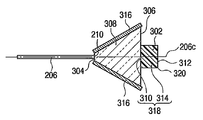
- FIG. 2B is an enlarged cross section showing the wavelength conversion unit and the light guide member in FIG.
- FIG. 2C is a front view of the wavelength conversion unit of FIG. 1 viewed from the exit end side.
- FIG. 3 is an enlarged perspective view showing the wavelength conversion unit and the light guide member of the illumination apparatus according to the modification of the first embodiment.
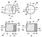
- FIG. 4A is an enlarged perspective view showing the wavelength conversion unit and the light guide member of the illumination apparatus according to the second embodiment of the present invention
- FIG. 4B is the wavelength of FIG. FIG.
- FIG. 4C is a front view of the conversion unit viewed from the emission end side
- FIG. 4C is an enlarged cross-sectional view of the wavelength conversion unit and the light guide member taken along the line CC in FIG. 4B
- FIG. 4D is an enlarged cross-sectional view of the wavelength conversion unit and the light guide member taken along the line DD in FIG. 4B
- FIG. 5A is an enlarged perspective view showing a wavelength conversion unit and a light guide member of a modified example of the illumination apparatus according to the second embodiment
- FIG. 5B is a wavelength diagram of FIG.
- FIG. 5C is a front view of the conversion unit as viewed from the exit end side
- FIG. 5C is an enlarged cross-sectional view of the wavelength conversion unit and the light guide member taken along the line CC in FIG. 5B.
- FIG. 5D is an enlarged cross-sectional view of the wavelength conversion unit and the light guide member taken along the line DD in FIG. 5B.
- FIG. 6 is an enlarged cross-sectional view of the wavelength conversion unit and the light guide member of the illumination apparatus according to the third embodiment of the present invention.
- FIGS. 1 and 2A to 2C A lighting apparatus according to a first embodiment of the present invention will be described with reference to FIGS. 1 and 2A to 2C. Note that some members are not shown in FIGS. 1 and 2A. In FIG. 2 (A), the light guide member and the incident portion of the wavelength conversion unit are separated from each other for explanation.
- the illumination device 100 is mainly divided into a light source unit 200 and a wavelength conversion unit 300, and excitation light emitted from the light source unit 200 is converted into the wavelength conversion unit 300. It is the structure which irradiates to the wavelength conversion member 302 which is the 1st optical member in. The detailed structure of each part will be described next.
- the light source unit 200 includes a semiconductor laser light source 202, a condensing lens 204, and a light guide member 206.
- the semiconductor laser light source 202 emits excitation light
- the condensing lens 204 condenses the excitation light on the excitation light incident end 208 of the light guide member 206.
- the wavelength conversion unit 300 includes an incident unit 304 that receives excitation light from the excitation light emission end 210 of the light guide member 206 of the light source unit 200 and an emission unit 306 that has a function of emitting desired illumination light to the irradiation object 400. have.
- the wavelength conversion unit 300 includes a wavelength conversion member 302 that is a first optical member, and a light transmission member 308.
- the wavelength conversion unit 300 converts the excitation light L1 guided by the light guide member 206 into desired wavelength converted light L2. To do.
- the wavelength converting member 302 has a cylindrical shape, and is sandwiched between the bottom surface 310 facing the excitation light emitting end 210 of the light guide member 206, the top surface 312 facing the bottom surface 310, and the bottom surface 310 and the top surface 312. Side surface 314. Further, the bottom surface 310 is separated from the excitation light emission end 210.
- the light transmission member 308 is formed so as to surround the side surface 314 and the bottom surface 310 of the wavelength conversion member 302.
- the light transmitting member 308 has a truncated cone shape in which the incident portion 304 is a first surface having a small diameter of a truncated cone, the emission portion 306 is a second surface having a large diameter, and the side surface is a tapered surface.
- the light transmitting member 308 has a property of transmitting both the excitation light L1 and the wavelength converted light L2 emitted from the wavelength converting member 302.
- a reflective portion 316 that is a second optical member is formed on the side surface of the light transmitting member 308, that is, on the inclined surface having a truncated cone shape.
- the reflection unit 316 has a function of converting incident light incident on the reflection unit 316 into reflected light by specular reflection or diffuse reflection.
- the incident light is wavelength-converted light L2 that has been wavelength-converted by the wavelength conversion member 302, and the reflected light is a wavelength whose traveling direction has been converted by regular reflection or diffuse reflection by the reflection unit 316. This is converted light L2.
- An ideal reflection surface can realize pure regular reflection or diffuse reflection, but in many cases, a component that regularly reflects and a component that diffusely reflect are mixed.
- a reflection part close to pure regular reflection can be realized by forming a thin film of metal or the like.
- the reflecting portion 316 that makes it easy to guide more reflected light to the emitting portion 306 side by utilizing the tapered shape.
- a reflection part close to pure diffuse reflection can be realized by applying oxide or resin powder.
- the reflection part 316 which is hard to be influenced by the shape of the reflection part 316 is realizable.
- Such a reflection part 316 may be formed not only on the entire side surface of the light transmitting member 308 but on a part thereof, but this embodiment is an example formed on the entire side surface of the light transmitting member 308.
- the upper surface 312 of the cylindrical wavelength conversion member 302 has an area smaller than that of the emission portion 306 and is disposed substantially concentrically with the emission portion 306. By arrange
- the thickness of the wavelength conversion member 302 is set so as to sufficiently convert the excitation light L1 into the wavelength conversion light L2.
- the light transmission member 308 is filled between the wavelength conversion member 302 and the reflection unit 316, and therefore, the light transmission member 308 extends from the incident unit 304 to the emission unit 306 over the entire lateral circumference of the wavelength conversion member 302. It will be formed continuously.
- the excitation light exit end 210 of the light guide member 206 is connected so that the excitation light L1 is incident on the incident portion 304. More specifically, the excitation light emitting end 210 is connected to the vicinity of the center of the incident portion 304 that is the first surface of the truncated cone of the light transmitting member 308.
- the relative positions of the excitation light emission end 210 and the wavelength conversion member 302 are such that the excitation light L1 emitted from the excitation light emission end 210 is substantially entirely irradiated onto the bottom surface 310 of the wavelength conversion member 302. And the size of the wavelength conversion member 302 is set.
- the excitation light L1 emitted from the light guide member 206 is configured such that the beam spot formed on the plane including the bottom surface 310 of the wavelength conversion member 302 is smaller than the bottom surface 310 of the wavelength conversion member 302. Yes.
- the beam spot is defined as a region having a light intensity greater than 1 / e 2 with respect to the maximum intensity of the excitation light, and e is the Napier number as the base of the natural body number.
- the taper angle of the light transmitting member 308 is preferably 20 deg with respect to the central axis 206 ⁇ / b> C of the light guide member 206.
- the wavelength conversion member 302 may have a cylindrical shape having a radius of 0.17 mm and a thickness of 0.5 mm. With this structure, the distance from the incident portion 304 to the bottom surface 310 of the wavelength conversion member 302 is about 0.6 mm.
- the light guide member 206 uses the above-described multimode optical fiber.
- the light transmitting member 308 is preferably made of a transparent material such as a transparent resin, general glass, or quartz glass. By selecting such a material, excitation light or wavelength-converted light can be efficiently transmitted, and more illumination light can be emitted from the emission unit 306.
- the reflecting portion 316 on the side surface of the light transmitting member 308 it is desirable to first deposit or plate a reflecting material on a sample whose upper and lower surfaces are masked.
- a metal film that is easy to be formed on the side surface of the light transmitting member 308 and has a high reflectance with respect to visible light is desirable.
- aluminum or silver should be selected. Note that, when a reflective material such as aluminum or silver is left in the air, it becomes cloudy or discolored, so that the reflectance decreases. In a severe case, the light transmission member 308 may be reached, and the function as a reflection surface may be deteriorated. Therefore, it is desirable to provide a protective film 317 as shown in FIG.
- the protective film 317 is preferably made of SiO 2 , copper or the like.
- a powder phosphor having an average particle diameter of 8 ⁇ m is dispersed in a silicone resin at a concentration of 10 wt%, and the resin is cured and hardened.
- the excitation light L1 emitted from the semiconductor laser light source 202 enters the light guide member 206 from the excitation light incident end 208 through the condenser lens 204 with high efficiency.
- the excitation light L1 incident on the light guide member 206 is guided inside the light guide member 206 and emitted from the excitation light emission end 210 of the light guide member 206 toward the light transmission member 308. At this time, the excitation light L1 is emitted with a spread angle corresponding to the numerical aperture (NA) of the light guide member 206 and the refractive index of the light transmitting member 308.
- NA numerical aperture
- the emitted excitation light L1 passes through the light transmission member 308 and is irradiated on the bottom surface 310 of the wavelength conversion member 302.
- the excitation light L1 is Most of the light is irradiated to the wavelength conversion member 302. As a result, almost no excitation light is directly emitted outside without passing through the wavelength conversion member 302.
- the excitation light L1 is irradiated on the wavelength conversion member 302 and is converted into wavelength conversion light L2 having a wavelength different from that of the excitation light L1 while being transmitted and scattered inside the wavelength conversion member 302.
- the wavelength converted light L2 is emitted in all directions regardless of the incident direction of the excitation light L1.
- a part is directly irradiated to the external irradiation object 400 from the upper surface 312 of the wavelength conversion member 302 or from the boundary portion between the side surface 314 and the upper surface 312, and another part is irradiated to the side surface 314 of the wavelength conversion member 302. Is irradiated from the emitting unit 306 to the external irradiation object 400 via the light transmitting member 308.
- the bottom surface 310 and the side surface 314 of the wavelength conversion member 302 are referred to as a first portion 318 of the first optical member, and the boundary portion between the side surface 314 and the top surface 312 is referred to as a second portion 320 of the first optical member.
- the wavelength conversion light L2 is emitted from the first part 318 or the second part 320 of the wavelength conversion member 302 toward the light transmission member 308.
- the wavelength-converted light L2 emitted from the first part 318 or the second part 320 toward the light transmission member 308 passes through the light transmission member 308, and then is formed on a side surface of the light transmission member 308.
- the reflecting part 316 has a tapered surface that opens to the emitting part 306 side, that is, the irradiation object 400 side
- the wavelength-converted light L2 reflected by the reflecting part 316 is compared with the original traveling direction. The component that proceeds toward the side increases.
- a part of the wavelength converted light L2 reflected by the reflecting unit 316 is directed again to the reflecting unit 316, another part is directed to the wavelength converting member 302, and the remaining part is the light transmitting member 308.
- the irradiation object 400 is irradiated from the emitting unit 306 via the.
- a part of the wavelength-converted light L2 that has been reflected once by the reflecting part 316 and emitted again toward the reflecting part 316 is further directed to the reflecting part 316 by repeating the above-mentioned process again, and another part is a wavelength converting member.
- the remaining part is ejected from the ejection unit 306 to the outside.
- the wavelength-converted light L2 directed toward the reflection unit 316 or the wavelength conversion member 302 repeats the above-described process thereafter.
- the wavelength-converted light L2 that travels toward the first part 318 enters the wavelength conversion member 302, but the wavelength conversion that travels toward the second part 320.
- the light L ⁇ b> 2 is not incident on the wavelength conversion member 302 and is emitted from the emission unit 306 to the outside. That is, the bottom surface 310 and the side surface 314 that are the first portion 318 of the wavelength conversion member 302 constitute a first region where the wavelength conversion light emitted from the reflection unit 316 that is the second optical member is incident.
- a boundary portion between the side surface 314 and the upper surface 312 which is the second portion 320 of 302 constitutes a second region where the wavelength-converted light is not incident together with the upper surface 312 of the wavelength conversion member 302.
- one of the wavelength-converted lights emitted from the first portion 318 that is the side surface 314 and the bottom surface 310 of the wavelength conversion member 302 and the second portion 320 that is the boundary portion between the upper surface 312 and the light transmission member 308.
- the part passes through the light transmission member 308 and is emitted from the emission part 306 to the outside without re-entering the wavelength conversion member 302. Since this light has little decrease in the amount of light due to self-absorption of the wavelength conversion member 302, it is possible to realize the illumination device 100 with high extraction efficiency of the wavelength conversion light.
- wavelength conversion light is emitted from the bottom surface 310 directly irradiated with excitation light at a higher rate than other surfaces.
- a part of the wavelength-converted light L2 emitted from the bottom surface 310 is emitted to the light transmission member 308 disposed on the light source unit 200 side with respect to the wavelength conversion member 302, and then passes through the reflection unit 316 and the light transmission member 308.
- the external irradiation object 400 can be irradiated with high light use efficiency without entering the wavelength conversion member 302 up to the emitting portion 306.
- the reflecting portion 316 and the wavelength conversion member 302 are separated from each other around the entire side of the wavelength conversion member 302. For this reason, the wavelength conversion light is not incident on the wavelength conversion member 302 again and is emitted from the emission unit 306 at a high rate, so that the light utilization efficiency is further increased.
- the light transmitting member 308 is made of glass or resin having a high transmittance with respect to the excitation light and the wavelength converted light, the loss of the excitation light and the wavelength converted light by the light transmitting member 308 is small, and the light utilization efficiency is further increased. Is expensive.
- the light transmitting member 308 has a truncated cone shape that spreads from the incident portion 304 to the emission portion 306. For this reason, every time the wavelength-converted light is reflected by the reflection portion 316 formed on the entire side surface, the emission direction is directed toward the emission portion 306, so that the light utilization efficiency becomes higher.
- the difference in refractive index at the interface between the bottom surface 310 and the side surface 314 is small, and the wavelength converted light generated inside the wavelength conversion member 302 is reduced. Almost injected into the light transmitting member 308. For this reason, the wavelength conversion light is less likely to stay inside the wavelength conversion member 302, and the light utilization efficiency is further increased.
- the wavelength conversion member 302 has a cylindrical shape, and the bottom surface 310 is larger than the beam spot irradiated with excitation light. Thereby, since the excitation light is efficiently applied to the wavelength conversion member 302 and converted into wavelength conversion light, the light utilization efficiency is further increased.
- the reflection portion 316 is formed on the entire side surface of the light transmission member 308. As a result, the wavelength-converted light is not emitted outside from other than the emission unit 306 and is not absorbed by other members, so that the light use efficiency from the emission unit 306 is high.
- the reflection part 316 uses a metal having a high reflectance with respect to visible light, there is little absorption at the time of reflection by the reflection part 316, and light utilization efficiency is high.
- the reflecting portion 316 is formed directly on the side surface of the light transmitting member 308, the wavelength-converted light L2 does not leak out of the light transmitting member 308, and the outside of the reflecting portion 316 is reflected during reflection. There is no influence of the structure. As a result, the reflecting portion 316 is manufactured separately from the light transmitting member 308, and compared with a configuration in which the reflecting portion 316 is adhered to the light transmitting member 308, it is reflected with high efficiency without transmitting an adhesive or the like. Low loss and high utilization efficiency.
- the wavelength conversion member 302 is not dropped, and the reliability is improved. It is possible to provide a lighting device 100 having a high height.
- the light transmission member 308 has a truncated cone shape in which the incident portion 304 is a first surface having a small diameter of a truncated cone, the emission portion 306 is a second surface having a large diameter, and the side surface is a tapered surface. It was supposed to be.
- the light transmitting member 308 does not have to have a truncated cone shape. For example, as shown in FIG. 3, even if the first surface and the second surface are configured as a cylindrical shape having the same size, they operate in the same manner as in the case of a truncated cone shape, and the same effect can be achieved.
- the light guide member 206 and the incident portion 304 of the wavelength conversion unit 300 are separated from each other for explanation.
- the reflecting portion 316 is directly formed on the first surface excluding the incident portion 304 in addition to the side surface of the light transmitting member 308.
- the first embodiment is an example in which the light transmission member 308 is installed over the entire side periphery of the wavelength conversion member 302. However, if the light transmission member 308 is installed in a part of the side of the wavelength conversion member 302 and, as a result, a part of the light transmission member 308 is continuously formed from the incident part 304 to the emission part 306, Although the effect obtained from the first embodiment is smaller, the same effect can be achieved.
- 4 and 5 show examples in which the region of the light transmitting member 308 that is continuous from the incident part 304 to the emission part 306 of the wavelength conversion unit 300 surrounds the wavelength conversion member 302, respectively.
- the emission unit 306 is the entire outer surface that is the same surface as the upper surface 312 of the wavelength conversion member 302 in the light transmission member 308 formed continuously, and the wavelength conversion reflected by the reflection unit 316 from all of this surface. Part of the light is emitted to the outside.
- the reflection unit 316 includes the wavelength conversion member 302 excluding the first surface excluding the incident unit 304 of the wavelength conversion unit 300 and the portion where the side surface of the wavelength conversion member 302 and the light transmission member 308 are in contact with each other. And the entire side surface of the light transmitting member 308.
- the reflective portion 316 may not be formed on the other side surface of the wavelength conversion member 302.
- the effect can be obtained as long as the reflecting portion 316 is formed on at least a part thereof. .
- the wavelength conversion member 302 is installed with its upper surface 312 in contact with the surface of the light transmission member 308 on the emission part 306 side.
- the wavelength conversion member 302 may be installed with the bottom surface 310 in contact with the surface of the light transmission member 308 on the emission portion 306 side.
- FIG. 6 shows an example in which such a wavelength conversion member 302 is installed in contact with the surface of the frustoconical light transmitting member 308 on the emission part 306 side.
- the emission unit 306 faces the area on the emission unit side of the frustoconical light transmitting member 308 that is not in contact with the wavelength conversion member 302 and the excitation light emission end 210 of the wavelength conversion member 302. All outer surfaces except surfaces. Wavelength-converted light is emitted from all of these surfaces.
- the shape of the light transmitting member 308 becomes simpler and easier to manufacture.
- the light transmitting member 308 and the wavelength conversion member 302 are in contact with each other only at the bottom surface 310 of the wavelength conversion member 302, so that the manufacturing is simple.
- the lighting device 100 can be provided with a special effect.
Landscapes
- Physics & Mathematics (AREA)
- Engineering & Computer Science (AREA)
- General Engineering & Computer Science (AREA)
- Spectroscopy & Molecular Physics (AREA)
- General Physics & Mathematics (AREA)
- Optics & Photonics (AREA)
- Non-Portable Lighting Devices Or Systems Thereof (AREA)
- Semiconductor Lasers (AREA)
Abstract
L'invention concerne un dispositif d'éclairage (100) qui comprend : une unité de source lumineuse (200) qui comporte une extrémité émettrice de lumière d'excitation (210) ; et une unité de conversion de longueur d'onde (300). Le dispositif d'éclairage (100) est caractérisé en ce que l'unité de conversion de longueur d'onde (300) est configurée à partir de : une partie d'incidence (304) qui est reliée à l'extrémité émettrice de lumière d'excitation (210) et sur laquelle une lumière d'excitation émise par l'unité de source lumineuse (200) est incidente ; un élément de conversion de longueur d'onde (302) qui convertit la lumière d'excitation incidente sur la partie d'incidence (304) en une lumière désirée convertie en longueur d'onde ; un élément transmetteur de lumière (308) qui comporte une fonction de transmission de la lumière d'excitation et de la lumière convertie en longueur d'onde ; une partie réfléchissante (316) qui comporte une fonction de réflexion d'au moins une partie de la lumière convertie en longueur d'onde de l'élément de conversion de longueur d'onde (302) ; et une partie d'émission (306) qui émet au moins une partie de la lumière convertie en longueur d'onde réfléchie vers l'extérieur par la partie réfléchissante (316). Le dispositif d'éclairage (100) est également caractérisé en ce qu'au moins une partie de l'élément transmetteur de lumière (308) de la partie d'incidence (304) à la partie d'émission (306) est formée en continu et la partie réfléchissante (316) est disposée sur une partie de la surface extérieure de l'élément transmetteur de lumière (308).
Priority Applications (1)
| Application Number | Priority Date | Filing Date | Title |
|---|---|---|---|
| US14/101,767 US9631794B2 (en) | 2011-06-13 | 2013-12-10 | Lighting apparatus |
Applications Claiming Priority (2)
| Application Number | Priority Date | Filing Date | Title |
|---|---|---|---|
| JP2011-131483 | 2011-06-13 | ||
| JP2011131483A JP6012936B2 (ja) | 2011-06-13 | 2011-06-13 | 照明装置 |
Related Child Applications (1)
| Application Number | Title | Priority Date | Filing Date |
|---|---|---|---|
| US14/101,767 Continuation US9631794B2 (en) | 2011-06-13 | 2013-12-10 | Lighting apparatus |
Publications (1)
| Publication Number | Publication Date |
|---|---|
| WO2012173085A1 true WO2012173085A1 (fr) | 2012-12-20 |
Family
ID=47357072
Family Applications (1)
| Application Number | Title | Priority Date | Filing Date |
|---|---|---|---|
| PCT/JP2012/064900 Ceased WO2012173085A1 (fr) | 2011-06-13 | 2012-06-11 | Dispositif d'éclairage |
Country Status (3)
| Country | Link |
|---|---|
| US (1) | US9631794B2 (fr) |
| JP (1) | JP6012936B2 (fr) |
| WO (1) | WO2012173085A1 (fr) |
Families Citing this family (7)
| Publication number | Priority date | Publication date | Assignee | Title |
|---|---|---|---|---|
| JP6061130B2 (ja) * | 2012-09-27 | 2017-01-18 | スタンレー電気株式会社 | 発光装置 |
| EP2957818B1 (fr) * | 2013-02-18 | 2020-01-01 | Koito Manufacturing Co., Ltd. | Appareil de lampe de véhicule |
| JP6323020B2 (ja) * | 2014-01-20 | 2018-05-16 | セイコーエプソン株式会社 | 光源装置およびプロジェクター |
| KR20160056089A (ko) * | 2014-11-11 | 2016-05-19 | 엘지이노텍 주식회사 | 발광 장치 |
| TWI598540B (zh) * | 2015-09-07 | 2017-09-11 | 台達電子工業股份有限公司 | 波長轉換模組與應用其的光源模組 |
| EP3956925A1 (fr) * | 2019-04-18 | 2022-02-23 | Lumileds Holding B.V. | Dispositif d'éclairage |
| JP7562977B2 (ja) * | 2020-03-31 | 2024-10-08 | 市光工業株式会社 | 車両用灯具 |
Citations (5)
| Publication number | Priority date | Publication date | Assignee | Title |
|---|---|---|---|---|
| WO2006038502A1 (fr) * | 2004-10-01 | 2006-04-13 | Nichia Corporation | Dispositif electroluminescent |
| JP2011066069A (ja) * | 2009-09-15 | 2011-03-31 | Sharp Corp | 発光装置、照明装置および光検知器 |
| JP2011129374A (ja) * | 2009-12-17 | 2011-06-30 | Sharp Corp | 車両用前照灯 |
| JP2011253015A (ja) * | 2010-06-01 | 2011-12-15 | Olympus Corp | 光結合デバイス及び光結合デバイスの実装方法 |
| JP2012074241A (ja) * | 2010-09-28 | 2012-04-12 | Olympus Corp | 光源装置 |
Family Cites Families (13)
| Publication number | Priority date | Publication date | Assignee | Title |
|---|---|---|---|---|
| US7837348B2 (en) * | 2004-05-05 | 2010-11-23 | Rensselaer Polytechnic Institute | Lighting system using multiple colored light emitting sources and diffuser element |
| JP2006261028A (ja) * | 2005-03-18 | 2006-09-28 | Stanley Electric Co Ltd | 放電灯具 |
| JP5083205B2 (ja) | 2006-03-10 | 2012-11-28 | 日亜化学工業株式会社 | 発光装置 |
| DE102006029203B9 (de) * | 2006-06-26 | 2023-06-22 | OSRAM Opto Semiconductors Gesellschaft mit beschränkter Haftung | Lichtemittierende Vorrichtung |
| JP5109498B2 (ja) | 2007-06-22 | 2012-12-26 | 日亜化学工業株式会社 | 発光装置 |
| US20090175043A1 (en) * | 2007-12-26 | 2009-07-09 | Night Operations Systems | Reflector for lighting system and method for making same |
| US8096668B2 (en) * | 2008-01-16 | 2012-01-17 | Abu-Ageel Nayef M | Illumination systems utilizing wavelength conversion materials |
| JP2011021062A (ja) * | 2009-07-13 | 2011-02-03 | Koito Mfg Co Ltd | 蛍光体、発光モジュール及び車両用灯具 |
| JP5478232B2 (ja) * | 2009-12-11 | 2014-04-23 | オリンパス株式会社 | 照明装置 |
| US20110280033A1 (en) * | 2010-05-17 | 2011-11-17 | Sharp Kabushiki Kaisha | Light-emitting device, illumination device, and vehicle headlamp |
| JP2011249538A (ja) * | 2010-05-26 | 2011-12-08 | Sharp Corp | 発光装置および照明装置 |
| EP2716967A4 (fr) * | 2011-05-27 | 2015-06-10 | Olympus Corp | Dispositif de source de lumière |
| JP5988705B2 (ja) * | 2012-06-01 | 2016-09-07 | オリンパス株式会社 | 照明装置 |
-
2011
- 2011-06-13 JP JP2011131483A patent/JP6012936B2/ja not_active Expired - Fee Related
-
2012
- 2012-06-11 WO PCT/JP2012/064900 patent/WO2012173085A1/fr not_active Ceased
-
2013
- 2013-12-10 US US14/101,767 patent/US9631794B2/en not_active Expired - Fee Related
Patent Citations (5)
| Publication number | Priority date | Publication date | Assignee | Title |
|---|---|---|---|---|
| WO2006038502A1 (fr) * | 2004-10-01 | 2006-04-13 | Nichia Corporation | Dispositif electroluminescent |
| JP2011066069A (ja) * | 2009-09-15 | 2011-03-31 | Sharp Corp | 発光装置、照明装置および光検知器 |
| JP2011129374A (ja) * | 2009-12-17 | 2011-06-30 | Sharp Corp | 車両用前照灯 |
| JP2011253015A (ja) * | 2010-06-01 | 2011-12-15 | Olympus Corp | 光結合デバイス及び光結合デバイスの実装方法 |
| JP2012074241A (ja) * | 2010-09-28 | 2012-04-12 | Olympus Corp | 光源装置 |
Also Published As
| Publication number | Publication date |
|---|---|
| JP2013004207A (ja) | 2013-01-07 |
| JP6012936B2 (ja) | 2016-10-25 |
| US9631794B2 (en) | 2017-04-25 |
| US20140098541A1 (en) | 2014-04-10 |
Similar Documents
| Publication | Publication Date | Title |
|---|---|---|
| JP5478232B2 (ja) | 照明装置 | |
| CN103562623B (zh) | 光源装置 | |
| JP6012936B2 (ja) | 照明装置 | |
| US20120212931A1 (en) | Light emitting device | |
| US20140085923A1 (en) | Light emitting device | |
| US20120106127A1 (en) | Light emitting device | |
| US8882321B2 (en) | Light source device with optical element and wavelength conversion member | |
| JP7187683B2 (ja) | 照明装置及び車両用ライト | |
| US9341344B2 (en) | Illumination apparatus | |
| WO2014003062A1 (fr) | Dispositif source de lumière | |
| JP2012248401A (ja) | 光源装置 | |
| CN101442086A (zh) | 发光二极管组合 | |
| US11384920B2 (en) | Illumination device | |
| JP5851123B2 (ja) | 照明装置 | |
| JP2019079765A (ja) | ライン光源及びこれを備えた光ラインセンサユニット | |
| JP5851119B2 (ja) | 光源装置 | |
| KR101507879B1 (ko) | 레이저광을 이용한 조명장치 | |
| JP6300080B2 (ja) | 発光装置、及び車両用灯具 | |
| JP7287491B2 (ja) | 光源装置 | |
| JP2011134509A (ja) | 照明器具 | |
| JP6239016B2 (ja) | 光源装置と内視鏡装置 | |
| JP2015026451A (ja) | 電球形照明装置 | |
| CN215259326U (zh) | 照明装置 | |
| TWI412803B (zh) | 導光棒及應用其之背光模組 | |
| JP2013089419A (ja) | 照明装置 |
Legal Events
| Date | Code | Title | Description |
|---|---|---|---|
| 121 | Ep: the epo has been informed by wipo that ep was designated in this application |
Ref document number: 12801435 Country of ref document: EP Kind code of ref document: A1 |
|
| NENP | Non-entry into the national phase |
Ref country code: DE |
|
| 122 | Ep: pct application non-entry in european phase |
Ref document number: 12801435 Country of ref document: EP Kind code of ref document: A1 |