WO2012173133A1 - 車輪用軸受装置の製造方法 - Google Patents
車輪用軸受装置の製造方法 Download PDFInfo
- Publication number
- WO2012173133A1 WO2012173133A1 PCT/JP2012/065087 JP2012065087W WO2012173133A1 WO 2012173133 A1 WO2012173133 A1 WO 2012173133A1 JP 2012065087 W JP2012065087 W JP 2012065087W WO 2012173133 A1 WO2012173133 A1 WO 2012173133A1
- Authority
- WO
- WIPO (PCT)
- Prior art keywords
- rolling
- simulated
- rolling element
- inner ring
- distance
- Prior art date
- Legal status (The legal status is an assumption and is not a legal conclusion. Google has not performed a legal analysis and makes no representation as to the accuracy of the status listed.)
- Ceased
Links
Images


Classifications
-
- F—MECHANICAL ENGINEERING; LIGHTING; HEATING; WEAPONS; BLASTING
- F16—ENGINEERING ELEMENTS AND UNITS; GENERAL MEASURES FOR PRODUCING AND MAINTAINING EFFECTIVE FUNCTIONING OF MACHINES OR INSTALLATIONS; THERMAL INSULATION IN GENERAL
- F16C—SHAFTS; FLEXIBLE SHAFTS; ELEMENTS OR CRANKSHAFT MECHANISMS; ROTARY BODIES OTHER THAN GEARING ELEMENTS; BEARINGS
- F16C43/00—Assembling bearings
- F16C43/04—Assembling rolling-contact bearings
-
- B—PERFORMING OPERATIONS; TRANSPORTING
- B21—MECHANICAL METAL-WORKING WITHOUT ESSENTIALLY REMOVING MATERIAL; PUNCHING METAL
- B21J—FORGING; HAMMERING; PRESSING METAL; RIVETING; FORGE FURNACES
- B21J9/00—Forging presses
- B21J9/02—Special design or construction
- B21J9/025—Special design or construction with rolling or wobbling dies
-
- B—PERFORMING OPERATIONS; TRANSPORTING
- B21—MECHANICAL METAL-WORKING WITHOUT ESSENTIALLY REMOVING MATERIAL; PUNCHING METAL
- B21K—MAKING FORGED OR PRESSED METAL PRODUCTS, e.g. HORSE-SHOES, RIVETS, BOLTS OR WHEELS
- B21K25/00—Uniting components to form integral members, e.g. turbine wheels and shafts, caulks with inserts, with or without shaping of the components
-
- B—PERFORMING OPERATIONS; TRANSPORTING
- B60—VEHICLES IN GENERAL
- B60B—VEHICLE WHEELS; CASTORS; AXLES FOR WHEELS OR CASTORS; INCREASING WHEEL ADHESION
- B60B27/00—Hubs
- B60B27/0005—Hubs with ball bearings
-
- B—PERFORMING OPERATIONS; TRANSPORTING
- B60—VEHICLES IN GENERAL
- B60B—VEHICLE WHEELS; CASTORS; AXLES FOR WHEELS OR CASTORS; INCREASING WHEEL ADHESION
- B60B27/00—Hubs
- B60B27/0094—Hubs one or more of the bearing races are formed by the hub
-
- F—MECHANICAL ENGINEERING; LIGHTING; HEATING; WEAPONS; BLASTING
- F16—ENGINEERING ELEMENTS AND UNITS; GENERAL MEASURES FOR PRODUCING AND MAINTAINING EFFECTIVE FUNCTIONING OF MACHINES OR INSTALLATIONS; THERMAL INSULATION IN GENERAL
- F16C—SHAFTS; FLEXIBLE SHAFTS; ELEMENTS OR CRANKSHAFT MECHANISMS; ROTARY BODIES OTHER THAN GEARING ELEMENTS; BEARINGS
- F16C19/00—Bearings with rolling contact, for exclusively rotary movement
- F16C19/02—Bearings with rolling contact, for exclusively rotary movement with bearing balls essentially of the same size in one or more circular rows
- F16C19/14—Bearings with rolling contact, for exclusively rotary movement with bearing balls essentially of the same size in one or more circular rows for both radial and axial load
- F16C19/18—Bearings with rolling contact, for exclusively rotary movement with bearing balls essentially of the same size in one or more circular rows for both radial and axial load with two or more rows of balls
- F16C19/181—Bearings with rolling contact, for exclusively rotary movement with bearing balls essentially of the same size in one or more circular rows for both radial and axial load with two or more rows of balls with angular contact
- F16C19/183—Bearings with rolling contact, for exclusively rotary movement with bearing balls essentially of the same size in one or more circular rows for both radial and axial load with two or more rows of balls with angular contact with two rows at opposite angles
- F16C19/184—Bearings with rolling contact, for exclusively rotary movement with bearing balls essentially of the same size in one or more circular rows for both radial and axial load with two or more rows of balls with angular contact with two rows at opposite angles in O-arrangement
- F16C19/186—Bearings with rolling contact, for exclusively rotary movement with bearing balls essentially of the same size in one or more circular rows for both radial and axial load with two or more rows of balls with angular contact with two rows at opposite angles in O-arrangement with three raceways provided integrally on parts other than race rings, e.g. third generation hubs
-
- B—PERFORMING OPERATIONS; TRANSPORTING
- B60—VEHICLES IN GENERAL
- B60B—VEHICLE WHEELS; CASTORS; AXLES FOR WHEELS OR CASTORS; INCREASING WHEEL ADHESION
- B60B2380/00—Bearings
- B60B2380/70—Arrangements
- B60B2380/77—Diameters of bearings at opposite ends of hub
- B60B2380/772—Identical diameters of bearings at opposite ends of hub
-
- B—PERFORMING OPERATIONS; TRANSPORTING
- B60—VEHICLES IN GENERAL
- B60B—VEHICLE WHEELS; CASTORS; AXLES FOR WHEELS OR CASTORS; INCREASING WHEEL ADHESION
- B60B2900/00—Purpose of invention
- B60B2900/30—Increase in
- B60B2900/325—Reliability
-
- F—MECHANICAL ENGINEERING; LIGHTING; HEATING; WEAPONS; BLASTING
- F16—ENGINEERING ELEMENTS AND UNITS; GENERAL MEASURES FOR PRODUCING AND MAINTAINING EFFECTIVE FUNCTIONING OF MACHINES OR INSTALLATIONS; THERMAL INSULATION IN GENERAL
- F16C—SHAFTS; FLEXIBLE SHAFTS; ELEMENTS OR CRANKSHAFT MECHANISMS; ROTARY BODIES OTHER THAN GEARING ELEMENTS; BEARINGS
- F16C2229/00—Setting preload
-
- F—MECHANICAL ENGINEERING; LIGHTING; HEATING; WEAPONS; BLASTING
- F16—ENGINEERING ELEMENTS AND UNITS; GENERAL MEASURES FOR PRODUCING AND MAINTAINING EFFECTIVE FUNCTIONING OF MACHINES OR INSTALLATIONS; THERMAL INSULATION IN GENERAL
- F16C—SHAFTS; FLEXIBLE SHAFTS; ELEMENTS OR CRANKSHAFT MECHANISMS; ROTARY BODIES OTHER THAN GEARING ELEMENTS; BEARINGS
- F16C2326/00—Articles relating to transporting
- F16C2326/01—Parts of vehicles in general
- F16C2326/02—Wheel hubs or castors
-
- Y—GENERAL TAGGING OF NEW TECHNOLOGICAL DEVELOPMENTS; GENERAL TAGGING OF CROSS-SECTIONAL TECHNOLOGIES SPANNING OVER SEVERAL SECTIONS OF THE IPC; TECHNICAL SUBJECTS COVERED BY FORMER USPC CROSS-REFERENCE ART COLLECTIONS [XRACs] AND DIGESTS
- Y10—TECHNICAL SUBJECTS COVERED BY FORMER USPC
- Y10T—TECHNICAL SUBJECTS COVERED BY FORMER US CLASSIFICATION
- Y10T29/00—Metal working
- Y10T29/49—Method of mechanical manufacture
- Y10T29/49636—Process for making bearing or component thereof
- Y10T29/49643—Rotary bearing
- Y10T29/49679—Anti-friction bearing or component thereof
Definitions
- the present invention is a method of manufacturing a wheel bearing device that rotatably supports a wheel of an automobile or the like, and in particular, can easily and efficiently manage a bearing clearance, and can provide a stable and accurate clearance.
- the present invention relates to a method for manufacturing a wheel bearing device.
- a wheel bearing device that rotatably supports a wheel of an automobile or the like is given a predetermined bearing preload in order to ensure a desired bearing rigidity.
- the management of the bearing preload amount is, for example, a so-called third generation, which includes a hub wheel integrally having a wheel mounting flange and an inner ring surface formed directly on the outer periphery, and an inner ring press-fitted into the hub wheel.
- a the abutment surface between the hub ring and the inner ring is accurately controlled, and when the hub ring and the outer joint member of the constant velocity universal joint are fastened by a fixing nut, the fixing nut The tightening torque (axial force) is set to a predetermined value.
- the bearing preload affects the bearing life and rigidity, but this bearing preload is greatly related to environmental problems such as safe driving of the vehicle and improvement of fuel consumption. That is, the bearing preload amount is proportional to the rotational torque of the bearing, and if the preload amount is reduced, the rotational torque can be reduced and the fuel efficiency can be improved.
- the relationship between the bearing tilt angle, which is the main factor of bearing rigidity, and the bearing preload amount is inversely proportional, so if the preload amount is increased, the bearing stiffness improves and the bearing tilt angle decreases, which occurs when the vehicle turns. The inclination of the brake rotor can be suppressed. Therefore, by setting the preload amount of such a bearing optimally, it is possible to provide a wheel bearing device that is excellent not only in terms of bearing life but also in terms of vehicle safety and fuel efficiency.
- FIG. 5A a method for managing the bearing preload (negative clearance).
- This preload monitor device measures the torque by rotating the bearing during assembly of the wheel bearing device, and sets the preload.
- the preload monitoring device 51 is in contact with the outer peripheral surface of the outer member 52 on the inner side of the vehicle body mounting flange 52b, and a gear 53 having a rubber member attached to the outer periphery, and a driving gear 54 meshing with the gear 53.
- a motor 55 that rotationally drives the drive gear 54
- a torque detector 56 that includes a power meter that detects the rotational torque of the motor 55, and a determiner 57 that compares the detected rotational torque with a predetermined value set in advance.
- the motor 55 is driven, the outer member 52 is rotated via the gears 54, 53, and the rotational torque of the outer member 52 is detected by the torque detector 56. Then, a preload amount is measured based on the detected rotational torque, and when the measured preload amount reaches a predetermined value set in advance, that is, a preload amount suitable for the wheel bearing device 50, the swing type caulking device 58 is retracted. Further, the rotational torque is monitored even after finishing the caulking process by the swing caulking device 58 to confirm that the preload amount is appropriate.
- FIG. 5B is a graph showing changes in the position A and the rotational torque T (vertical axis) of the caulking die 58a in the swinging caulking device 58 with respect to the caulking processing time t (horizontal axis).
- the preload monitoring device 51 detects the rotational torque of the bearing, measures the preload amount based on the detected rotational torque, and determines whether or not the measured preload amount is an appropriate value.
- the dynamic caulking device 58 is operated to accurately and stably manage the preload amount of the bearing.
- the groove diameters of the outer member 52, the hub wheel 61, and the inner ring 62 press-fitted into the hub ring 61 are finished in a desired range. In such a case, it is possible to manage the preload amount of the bearing accurately and stably using such rotational torque as a medium, but it is difficult to accurately manage if the groove diameters vary. Further, since rotational torque is detected during processing by the swing type caulking device, it is not possible to replace parts and reassemble them.
- the present invention has been made in view of such circumstances, and a wheel bearing device manufacturing method that can easily and efficiently perform bearing clearance management and can stably and accurately provide a clearance. It is intended to provide.
- the invention described in claim 1 of the present invention has a vehicle body mounting flange integrally attached to the vehicle body on the outer periphery, and a double row outer rolling surface is integrally formed on the inner periphery.
- An outer rolling member formed integrally with a wheel mounting flange for mounting a wheel at one end portion, an inner rolling surface facing one of the outer rolling surfaces of the double row on the outer periphery, and the inner rolling surface
- a hub ring formed with a small-diameter step portion extending in the axial direction from the shoulder to the inner ring, and an inner member formed of an inner ring press-fitted into the small-diameter step portion of the hub ring via a predetermined shimeiro, and the inner member
- a double row rolling element that is rotatably accommodated between both rolling surfaces of the outer member via a cage, wherein the double row of the outer member is Outer rolling surface from the contact point between one outer rolling surface and the rolling element.
- the rolling contact with the other outer rolling contact surface from the contact point between one outer rolling contact surface and the rolling element of the double row outer rolling contact surfaces of the outer member is measured.
- the bearing clearance device for a wheel that can easily and efficiently perform the bearing clearance management and can provide a stable and accurate clearance is provided.
- a manufacturing method can be provided.
- the bearing clearance can be set before assembling the inner ring, the outer member, and the hub ring, it is possible to replace and reassemble parts and the like, thereby reducing the manufacturing cost.
- the inner diameter of the inner ring and the outer diameter of the small-diameter step portion of the hub ring are measured to calculate the inner ring and compare with the reference value of the model product. If the difference is corrected, the set value of the bearing clearance can be changed in accordance with the variation of the bearing clearance depending on the expansion of the inner ring due to press fitting, and a more accurate bearing clearance can be provided.
- the measuring jig for the outer member includes a simulated inner ring, a simulated hub ring, and the rolling elements having the same shape and dimensions as the inner raceway of the inner ring and the hub ring.
- a plurality of outer rolling surfaces of the outer member and the inner rolling surfaces of the simulated inner ring and the simulated hub ring are brought into contact with each other through the simulated rolling elements, and the distance Ho is If measured, accurate and stable dimension measurement can be performed over a long period of time.
- the distance Ho is measured in a state where the outer member is rotated, a minute inclination of the outer member or a shape error of the outer rolling surface is obtained. Can be corrected, and a stable measurement value can be obtained.
- the inner ring measuring jig is the same size as the simulated outer member and the rolling element having the same shape and dimensions as the double row outer rolling surface of the outer member. If the distance Hi is measured, the inner rolling surface of the inner ring and the inner rolling surface of the inner ring are brought into contact with the double rolling outer rolling surface of the simulated outer member via the simulated rolling member. Accurate and stable dimensional measurement can be performed over a period of time.
- the hub wheel measuring jig is the same as the simulated outer member and the rolling element having the same shape and dimensions as the double row outer rolling surface of the outer member.
- a simulated rolling element of a size, and the inner rolling surface of the hub wheel and the simulated rolling member are brought into contact with a double row outer rolling surface of the simulated outer member, and the distance Hh is measured. Therefore, accurate and stable dimension measurement can be performed over a long period of time.
- a method for manufacturing a wheel bearing device includes an outer member integrally including a vehicle body mounting flange for mounting to a vehicle body on an outer periphery, and an outer rolling surface of a double row integrally formed on an inner periphery.
- a hub ring formed with a small-diameter step portion extending in the axial direction, an inner member made of an inner ring press-fitted into the small-diameter step portion of the hub ring via a predetermined shimeshiro, and the inner member and the outer member
- a method for manufacturing a wheel bearing device including a double row rolling element that is slidably accommodated between both rolling surfaces via a cage, out of the double row outer rolling surfaces of the outer member From the contact point between one outer rolling surface and the rolling element, the other outer rolling surface and the rolling element The distance Ho to the contact point, the distance Hi from the contact point between the inner rolling surface of the inner ring and the rolling element to the small end surface of the inner ring, and the contact between the inner rolling surface of the hub ring and the rolling element The distance Hh from the
- a rolling element having an optimal diameter is selected from among the rolling elements for correction, a wheel capable of easily and efficiently performing bearing clearance management and providing a stable and accurate clearance.
- a method for manufacturing a bearing device for a vehicle can be provided. Further, since the bearing clearance can be set before assembling the inner ring, the outer member, and the hub ring, it is possible to replace and reassemble parts and the like, thereby reducing the manufacturing cost.
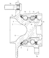
- FIG. 1 It is a longitudinal section showing one embodiment of a wheel bearing device concerning the present invention.
- (A) is explanatory drawing which shows the measurement site
- (b) is explanatory drawing which shows the measuring method of the inner ring
- (A) is explanatory drawing which shows the measurement site
- (b) is explanatory drawing which shows the measuring method of (a).
- A) is explanatory drawing which shows the measurement site
- (b) is explanatory drawing which shows the measuring method of (a).
- (A) is the schematic for demonstrating the prior art
- (b) is a graph which shows the change of the crimping position and rotational torque of a rocking
- a wheel bearing device including a double row rolling element accommodated freely, contact between one outer rolling surface of the outer row rolling surface of the outer member and the rolling element.
- the distance Ho from the point to the contact point between the other outer rolling surface and the rolling element, and the inner side of the inner ring A distance Hi from the contact point between the running surface and the rolling element to the small end surface of the inner ring, and a distance Hh from the contact point between the inner rolling surface of the hub ring and the rolling element to the shoulder of the hub ring
- the distance difference ⁇ H (Hi + Hh ⁇ Ho) is compared with the reference value of the model product, the difference between the reference value and the measured value, the inner ring inner diameter and the hub ring small diameter step portion.
- the outer diameter was measured and the inner ring was calculated, compared with the reference value of the model, and the rolling element having the optimum diameter was selected from the rolling elements to correct the difference.
- FIG. 1 is a longitudinal sectional view showing an embodiment of a wheel bearing device according to the present invention
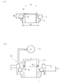
- FIG. 2 (a) is an explanatory view showing a measurement site of the inner ring of FIG. 1
- FIG. 3A is an explanatory diagram showing the measurement part of the outer member in FIG. 1
- FIG. 3B is an explanatory diagram showing the measurement method in FIG. )
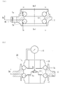
- Is an explanatory view showing a measurement site of the hub wheel of FIG.
- (b) is an explanatory view showing a measurement method of (a).
- the side closer to the outer side of the vehicle when assembled to the vehicle is referred to as the outer side (left side in FIG. 1)
- the side closer to the center is referred to as the inner side (right side in FIG. 1).
- This wheel bearing device is for a driven wheel referred to as a third generation, and is a double row rolling element housed in a freely rollable manner between the inner member 1 and the outer member 2, and both members 1 and 2. (Balls) 3 and 3.
- the inner member 1 includes a hub ring 4 and an inner ring 5 press-fitted into the hub ring 4 through a predetermined shimiro.
- the hub wheel 4 integrally has a wheel mounting flange 6 for mounting a wheel (not shown) at an end portion on the outer side, and has one (outer side) inner rolling surface 4a on the outer periphery and the inner rolling surface.
- a small diameter step 4b extending in the axial direction from the surface 4a is formed.
- Hub bolts 6a are planted on the wheel mounting flange 6 at equal intervals in the circumferential direction.
- a mortar-shaped recess 10 is formed at the outer end of the hub wheel 4.
- the depth of the recess 10 is a depth from the outer end surface of the hub wheel 4 to the vicinity of the groove bottom of the inner rolling surface 4a, and the outer side portion of the hub wheel 4 is formed to have a substantially uniform thickness. ing. As a result, the conflicting problems of the hub wheel 4 that are lighter, more compact and more rigid can be solved.
- the inner ring 5 is formed with the other (inner side) inner raceway surface 5a on the outer periphery and is press-fitted into the small-diameter stepped portion 4b of the hub wheel 4 to form a back-to-back type double row angular contact ball bearing.
- the inner ring 5 is fixed in the axial direction in a state where a predetermined bearing preload is applied by a caulking portion 4c formed by plastic deformation of the end portion of 4b.
- the inner ring 5 and the rolling element 3 are made of high carbon chrome steel such as SUJ2, and are hardened in the range of 58 to 64 HRC up to the core portion by quenching.
- the hub wheel 4 is made of medium and high carbon steel containing 0.40 to 0.80 wt% of carbon such as S53C, and the inner raceway surface 4a and the inner side base portion 6c of the wheel mounting flange 6 to the small diameter step portion 4b.
- the surface hardness is set to a range of 58 to 64 HRC by induction hardening.
- the caulking portion 4c is kept in the surface hardness after forging.
- the outer member 2 integrally has a vehicle body mounting flange 2b to be attached to a knuckle (not shown) on the outer periphery, and the inner rolling surface 4a of the hub wheel 4 and the inner rolling surface 5a of the inner ring 5 on the inner periphery.
- Double row outer rolling surfaces 2a, 2a facing each other are integrally formed.
- Double-row rolling elements 3 and 3 are accommodated between these rolling surfaces and are held by a cage 7 so as to be freely rollable.
- This outer member 2 is made of medium and high carbon steel containing 0.40 to 0.80 wt% of carbon such as S53C, and at least the double row outer rolling surfaces 2a and 2a have a surface hardness of 58 to 64 HRC by induction hardening. Hardened to range. Seals 8 and 9 are attached to the opening of the annular space formed between the outer member 2 and the inner member 1, and leakage of grease sealed inside the bearing and rainwater from the outside. And dust are prevented from entering the bearing.
- double row angular contact ball bearing which used the ball for the rolling element 3 was illustrated here, it is not restricted to this, The double row tapered roller bearing which uses the tapered roller for the rolling element 3 may be sufficient.
- the measurement site of the inner ring 5 includes a touch diameter (a diameter of a point that contacts the rolling element 3 with a predetermined contact angle) di, and a touch part pitch length.
- the distance (distance from the touch point to the small end surface 5b) Hi and the inner diameter Di are measured.
- the measurement of the touch part pitch length Hi of the inner ring 5 is performed by a measuring jig 11 as shown in FIG.
- the measuring jig 11 includes a simulated outer member 12, a simulated rolling element 13, and a pressing jig 14.
- the simulated outer member 12 is externally fitted to the inner ring 5 via the simulated rolling element 13, and the simulated rolling element 13 is brought into contact with the outer rolling surface 2a and the inner rolling surface 5a of the inner ring 5 at a predetermined measurement pressure.
- the touch portion pitch length Hi is measured using the distance measuring device 15 such as a dial gauge. Thereby, the minute inclination of the inner ring
- the measurement sites of the outer member 2 are measured by touch diameters Do1 and Do2 and a touch portion pitch length Ho.
- the dimensions can be managed accurately and accurately.
- the measurement of the touch part pitch length Ho of the outer member 2 is performed by a measuring jig 16 as shown in FIG.
- the measuring jig 16 includes a simulated inner ring 17, a simulated hub ring 18, and a simulated rolling element 13.
- a simulated inner ring 17 and a simulated hub ring 18 are fitted into the outer member 2 via the simulated rolling element 13, and the inner rolling surfaces 5a, 4a and the outer rolling surface of the outer member 2 are double row.
- the touch portion pitch length Ho is measured using a distance measuring device 15 such as a dial gauge. The Thereby, the minute inclination of the outer member 2 and the shape error of the outer rolling surface 2a can be corrected, and a stable measurement value can be obtained.
- the measurement part of the hub wheel 4 is measured by the touch diameter dh, the touch part pitch length Hh, and the outer diameter Dh of the small diameter step part 4b.
- the measurement of the touch part pitch length (distance from the touch point to the shoulder part 4d) Hh of the hub wheel 4 is performed by a measurement jig 19 as shown in FIG.
- the measuring jig 19 includes a simulated outer member 12, a simulated rolling element 13, and a pressing jig 20.
- the simulated outer member 12 is fitted on the hub wheel 4 via the simulated rolling element 13, and the simulated rolling element 13 is placed on the outer rolling surface 2 a and the inner rolling surface 4 a of the hub wheel 4 with a predetermined measurement pressure.
- the touch portion pitch length Hh is measured by using a distance measuring device 15 such as a dial gauge while the hub wheel 4 is rotated. Thereby, the minute inclination of the hub wheel 4 and the shape error of the inner rolling surface 4a can be corrected, and a stable measurement value can be obtained.
- the measurement information described above is taken into the computer. Specifically, the touch diameter di and the touch part pitch length Hi of the inner ring 5, the touch diameters Do1 and Do2 and the touch part pitch length Ho of the outer member 2, and the touch diameter dh and the touch part pitch length of the hub wheel 4 are shown.
- the information of Hh is taken into the computer, and each numerical value is calculated in consideration of the diameter of the rolling element 3 prepared in advance, and the optimum diameter of the rolling element 3 is selected based on these pieces of information.
- the wheel bearing device according to the present invention can be applied to a third-generation wheel bearing device regardless of whether it is for driving wheels or driven wheels.
Landscapes
- Engineering & Computer Science (AREA)
- Mechanical Engineering (AREA)
- General Engineering & Computer Science (AREA)
- Rolling Contact Bearings (AREA)
- Mounting Of Bearings Or Others (AREA)
Abstract
【課題】軸受のすきま管理を容易に、かつ効率良く行うことができると共に、安定して正確なすきまを付与できる車輪用軸受装置の製造方法を提供する。 【解決手段】外方部材2の複列の外側転走面2aのうち一方の外側転走面2aと転動体3との接触点から他方の外側転走面2aと転動体3との接触点までの距離Hoと、内輪5の内側転走面5aと転動体3との接触点から当該内輪5の小端面5bまでの距離Hiと、ハブ輪4の内側転走面4aと転動体3との接触点から当該ハブ輪4の肩部4dまでの距離Hhとを測定して、距離の差ΔH=(Hi+Hh-Ho)を模範品の基準値と比較し、この基準値と測定値との差分および内輪5の内径Diとハブ輪4の小径段部4bの外径Dhとを測定して内輪5のシメシロを算出して模範品の基準値と比較し、その差分を補正するために転動体3のうち最適な直径の転動体3を選択するようにした。
Description
本発明は、自動車等の車輪を回転自在に支承する車輪用軸受装置の製造方法、特に、軸受のすきま管理を容易に、かつ効率良く行うことができると共に、安定して正確なすきまを付与できる車輪用軸受装置の製造方法に関するものである。
従来から自動車等の車輪を回転自在に支承する車輪用軸受装置は、所望の軸受剛性を確保するため所定の軸受予圧が付与されている。軸受予圧量の管理は、例えば、車輪取付フランジを一体に有し、外周に直接内側転走面が形成されたハブ輪、およびこのハブ輪に圧入された内輪とを備えた、所謂第3世代と呼称される車輪用軸受装置においては、ハブ輪と内輪との突き合せ面を精度良く管理すると共に、ハブ輪と等速自在継手の外側継手部材とを固定ナットによって締結する際、この固定ナットの締付トルク(軸力)を所定値に設定することにより行われている。
当然、軸受予圧量は軸受寿命や剛性に影響するものであるが、それだけでなく、車両の安全走行や燃費向上等の環境問題に対して、この軸受予圧量は大きく関わってくる。すなわち、軸受予圧量は軸受の回転トルクと比例関係にあり、予圧量を低下させれば回転トルクが軽減でき燃費向上へ貢献することがきる。一方、軸受の剛性の主要因となる軸受傾き角と軸受予圧量との関係は反比例関係にあるため、予圧量を大きくすれば軸受剛性が向上して軸受傾き角は減少し、車両旋回時に発生するブレーキロータの傾きを抑制することができる。したがって、このような軸受の予圧量を最適に設定することにより、軸受の寿命だけでなく、車両の安全性や燃費向上の面で優れた車輪用軸受装置を提供することができる。
このような車輪用軸受装置の製造工程において、軸受の予圧(負すきま)を管理する方法として図5(a)に示すものが知られている。この予圧モニター装置は、車輪用軸受装置の組立加工時に軸受を回転させてトルクを測定し、予圧設定を行うものである。この予圧モニター装置51は、外方部材52における車体取付フランジ52bの内方側の外周面と接触し、外周にゴム部材が取り付けられた歯車53と、この歯車53と噛合する駆動用歯車54と、この駆動歯車54を回転駆動するモータ55と、このモータ55の回転トルクを検出する電力計からなるトルク検出器56と、検出された回転トルクを予め設定された所定値と比較する判定器57とを備えている。
予圧モニター装置51では、モータ55を駆動し、歯車54、53を介して外方部材52を回転させ、外方部材52の回転トルクをトルク検出器56で検出する。そして、検出された回転トルクに基き予圧量を測定し、測定された予圧量が予め設定された所定値、つまり車輪用軸受装置50に適した予圧量に達した場合、揺動型加締装置58を後退させる。さらに、揺動型加締装置58による加締加工を終了した後も回転トルクを監視し、その予圧量が適正であることを確認する。
図5(b)は、加締加工時間t(横軸)に対する揺動型加締装置58における加締型58aの位置Aおよび回転トルクT(縦軸)の変化を示すグラフである。加締型58aの位置Aを徐々に降下させて加締加工を開始すると、ある時点t0から車輪用軸受装置50に予圧が加わり、回転トルクTが変動し始める。その変動幅が予め設定された所定値Δにまで達すると(t1)、車輪用軸受装置50に適した予圧が加わったと判断して加締加工を終了する。その後、加締型58aの位置Aを原点に復帰させる。こうした予圧モニター装置51により、車輪用軸受装置50の組立加工時に軸受を回転させて回転トルクを測定し、予圧量の設定を行うことができる(例えば、特許文献1参照。)。
こうした従来の技術は、予圧モニター装置51で軸受の回転トルクを検出し、この検出された回転トルクに基き予圧量を測定すると共に、測定された予圧量が適性値か否かを判断して揺動型加締装置58を操作し、軸受の予圧量を精度良く、かつ安定して管理するものである。然しながら、この種のセルフリテイン構造からなる車輪用軸受装置の製造工程において、外方部材52やハブ輪61およびハブ輪61に圧入される内輪62の各溝径寸法が所望の範囲に仕上げられている場合は、こうした回転トルクを媒体として軸受の予圧量を精度良く、かつ安定して管理することができるが、各溝径にバラツキがある場合は精度良く管理するのは難しい。また、揺動型加締装置による加工中に回転トルクを検出するため、部品等を一部取り替えて再組立することができない。
本発明は、このような事情に鑑みてなされたもので、軸受のすきま管理を容易に、かつ効率良く行うことができると共に、安定して正確なすきまを付与できる車輪用軸受装置の製造方法を提供することを目的としている。
係る目的を達成すべく、本発明のうち請求項1記載の発明は、外周に車体に取り付けられるための車体取付フランジを一体に有し、内周に複列の外側転走面が一体に形成された外方部材と、一端部に車輪を取り付けるための車輪取付フランジを一体に有し、外周に前記複列の外側転走面の一方に対向する内側転走面と、この内側転走面から肩部を介して軸方向に延びる小径段部が形成されたハブ輪、およびこのハブ輪の小径段部に所定のシメシロを介して圧入された内輪からなる内方部材と、この内方部材と前記外方部材の両転走面間に保持器を介して転動自在に収容された複列の転動体とを備えた車輪用軸受装置の製造方法において、前記外方部材の複列の外側転走面のうち一方の外側転走面と前記転動体との接触点から他方の外側転走面と前記転動体との接触点までの距離Hoと、前記内輪の内側転走面と前記転動体との接触点から当該内輪の小端面までの距離Hiと、前記ハブ輪の内側転走面と前記転動体との接触点から当該ハブ輪の肩部までの距離Hhとを測定して、前記距離の差ΔH=(Hi+Hh-Ho)を模範品の基準値と比較し、この基準値と前記測定値との差分を補正するために前記転動体のうち最適な直径の転動体を選択するようにした。
このように、第3世代構造の車輪用軸受装置において、外方部材の複列の外側転走面のうち一方の外側転走面と転動体との接触点から他方の外側転走面と転動体との接触点までの距離Hoと、内輪の内側転走面と転動体との接触点から当該内輪の小端面までの距離Hiと、ハブ輪の内側転走面と転動体との接触点から当該ハブ輪の肩部までの距離Hhとを測定して、距離の差ΔH=(Hi+Hh-Ho)を模範品の基準値と比較し、この基準値と測定値との差分を補正するために転動体のうち最適な直径の転動体を選択するようにしたので、軸受のすきま管理を容易に、かつ効率良く行うことができると共に、安定して正確なすきまを付与できる車輪用軸受装置の製造方法を提供することができる。また、内輪、外方部材およびハブ輪を組立前に軸受すきまを設定することができるため、部品等を取り替えて再組立することが可能となるため、製造コストを低減させることができる。
好ましくは、請求項2に記載の発明のように、前記内輪の内径と前記ハブ輪の小径段部の外径とを測定して前記内輪のシメシロを算出して模範品の基準値と比較し、その差分が補正されていれば、圧入による内輪の膨張に依存する軸受すきまの変動に応じて軸受すきまの設定値を変えることができ、一層正確な軸受すきまを付与することができる。
また、請求項3に記載の発明のように、前記外方部材の測定治具が、前記内輪とハブ輪の内側転走面と同じ形状・寸法の模擬内輪と模擬ハブ輪および前記転動体と同寸法の模擬転動体を備え、前記外方部材の複列の外側転走面と前記模擬転動体を介して前記模擬内輪と模擬ハブ輪の内側転走面とそれぞれ接触させ、前記距離Hoが測定されていれば、長期間に亘って正確かつ安定した寸法測定を行うことができる。
好ましくは、請求項4に記載の発明のように、前記外方部材を回転させた状態で、前記距離Hoが測定されていれば、外方部材の微小な傾きや外側転走面の形状誤差を修正することができ、安定した測定値を得ることができる。
また、請求項5に記載の発明のように、前記内輪の測定治具が、前記外方部材の複列の外側転走面と同じ形状・寸法の模擬外方部材および前記転動体と同寸法の模擬転動体を備え、前記内輪の内側転走面と前記模擬転動体を介して前記模擬外方部材の複列の外側転走面と接触させ、前記距離Hiが測定されていれば、長期間に亘って正確かつ安定した寸法測定を行うことができる。
好ましくは、請求項6に記載の発明のように、前記内輪を回転させた状態で、前記距離Hiが測定されていれば、内輪の微小な傾きや内側転走面の形状誤差を修正することができ、安定した測定値を得ることができる。
また、請求項7に記載の発明のように、前記ハブ輪の測定治具が、前記外方部材の複列の外側転走面と同じ形状・寸法の模擬外方部材および前記転動体と同寸法の模擬転動体を備え、前記ハブ輪の内側転走面と前記模擬転動体を介して前記模擬外方部材の複列の外側転走面と接触させ、前記距離Hhが測定されていれば、長期間に亘って正確かつ安定した寸法測定を行うことができる。
好ましくは、請求項8に記載の発明のように、前記ハブ輪を回転させた状態で、前記距離Hhが測定されていれば、ハブ輪の微小な傾きや内側転走面の形状誤差を修正することができ、安定した測定値を得ることができる。
本発明に係る車輪用軸受装置の製造方法は、外周に車体に取り付けられるための車体取付フランジを一体に有し、内周に複列の外側転走面が一体に形成された外方部材と、一端部に車輪を取り付けるための車輪取付フランジを一体に有し、外周に前記複列の外側転走面の一方に対向する内側転走面と、この内側転走面から肩部を介して軸方向に延びる小径段部が形成されたハブ輪、およびこのハブ輪の小径段部に所定のシメシロを介して圧入された内輪からなる内方部材と、この内方部材と前記外方部材の両転走面間に保持器を介して転動自在に収容された複列の転動体とを備えた車輪用軸受装置の製造方法において、前記外方部材の複列の外側転走面のうち一方の外側転走面と前記転動体との接触点から他方の外側転走面と前記転動体との接触点までの距離Hoと、前記内輪の内側転走面と前記転動体との接触点から当該内輪の小端面までの距離Hiと、前記ハブ輪の内側転走面と前記転動体との接触点から当該ハブ輪の肩部までの距離Hhとを測定して、前記距離の差ΔH=(Hi+Hh-Ho)を模範品の基準値と比較し、この基準値と前記測定値との差分を補正するために前記転動体のうち最適な直径の転動体を選択するようにしたので、軸受のすきま管理を容易に、かつ効率良く行うことができると共に、安定して正確なすきまを付与できる車輪用軸受装置の製造方法を提供することができる。また、内輪、外方部材およびハブ輪を組立前に軸受すきまを設定することができるため、部品等を取り替えて再組立することが可能となるため、製造コストを低減させることができる。
外周に車体に取り付けられるための車体取付フランジを一体に有し、内周に複列の外側転走面が一体に形成された外方部材と、一端部に車輪を取り付けるための車輪取付フランジを一体に有し、外周に前記複列の外側転走面の一方に対向する内側転走面と、この内側転走面から肩部を介して軸方向に延びる小径段部が形成されたハブ輪、およびこのハブ輪の小径段部に所定のシメシロを介して圧入された内輪からなる内方部材と、この内方部材と前記外方部材の両転走面間に保持器を介して転動自在に収容された複列の転動体とを備えた車輪用軸受装置の製造方法において、前記外方部材の複列の外側転走面のうち一方の外側転走面と前記転動体との接触点から他方の外側転走面と前記転動体との接触点までの距離Hoと、前記内輪の内側転走面と前記転動体との接触点から当該内輪の小端面までの距離Hiと、前記ハブ輪の内側転走面と前記転動体との接触点から当該ハブ輪の肩部までの距離Hhとを測定して、前記距離の差ΔH=(Hi+Hh-Ho)を模範品の基準値と比較し、この基準値と前記測定値との差分および前記内輪の内径と前記ハブ輪の小径段部の外径とを測定して前記内輪のシメシロを算出して模範品の基準値と比較し、その差分を補正するために前記転動体のうち最適な直径の転動体を選択するようにした。
以下、本発明の実施の形態を図面に基づいて詳細に説明する。
図1は、本発明に係る車輪用軸受装置の一実施形態を示す縦断面図、図2(a)は、図1の内輪の測定部位を示す説明図、(b)は、(a)の内輪の測定方法を示す説明図、図3(a)は、図1の外方部材の測定部位を示す説明図、(b)は、(a)の測定方法を示す説明図、図4(a)は、図1のハブ輪の測定部位を示す説明図、(b)は、(a)の測定方法を示す説明図である。なお、以下の説明では、車両に組み付けた状態で車両の外側寄りとなる側をアウター側(図1の左側)、中央寄り側をインナー側(図1の右側)という。
図1は、本発明に係る車輪用軸受装置の一実施形態を示す縦断面図、図2(a)は、図1の内輪の測定部位を示す説明図、(b)は、(a)の内輪の測定方法を示す説明図、図3(a)は、図1の外方部材の測定部位を示す説明図、(b)は、(a)の測定方法を示す説明図、図4(a)は、図1のハブ輪の測定部位を示す説明図、(b)は、(a)の測定方法を示す説明図である。なお、以下の説明では、車両に組み付けた状態で車両の外側寄りとなる側をアウター側(図1の左側)、中央寄り側をインナー側(図1の右側)という。
この車輪用軸受装置は第3世代と呼称される従動輪用であって、内方部材1と外方部材2、および両部材1、2間に転動自在に収容された複列の転動体(ボール)3、3とを備えている。内方部材1は、ハブ輪4と、このハブ輪4に所定のシメシロを介して圧入された内輪5とからなる。
ハブ輪4は、アウター側の端部に車輪(図示せず)を取り付けるための車輪取付フランジ6を一体に有し、外周に一方(アウター側)の内側転走面4aと、この内側転走面4aから軸方向に延びる小径段部4bが形成されている。車輪取付フランジ6にはハブボルト6aが周方向等配に植設されている。
また、ハブ輪4のアウター側の端部にはすり鉢状の凹所10が形成されている。この凹所10の深さは、ハブ輪4のアウター側の端面から内側転走面4aの溝底付近までの深さとされ、ハブ輪4のアウター側の部位が略均一な肉厚に形成されている。これにより、ハブ輪4の軽量・コンパクト化と高剛性化という相反する課題を解決することができる。
内輪5は、外周に他方(インナー側)の内側転走面5aが形成され、ハブ輪4の小径段部4bに圧入されて背面合せタイプの複列アンギュラ玉軸受を構成すると共に、小径段部4bの端部を塑性変形させて形成した加締部4cによって所定の軸受予圧が付与された状態で、内輪5が軸方向に固定されている。なお、内輪5および転動体3はSUJ2等の高炭素クロム鋼で形成され、ズブ焼入れによって芯部まで58~64HRCの範囲に硬化処理されている。
ハブ輪4はS53C等の炭素0.40~0.80wt%を含む中高炭素鋼で形成され、内側転走面4aをはじめ、車輪取付フランジ6のインナー側の基部6cから小径段部4bに亙って高周波焼入れによって表面硬さを58~64HRCの範囲に硬化処理されている。なお、加締部4cは鍛造加工後の表面硬さのままとされている。これにより、車輪取付フランジ6に負荷される回転曲げ荷重に対して充分な機械的強度を有し、内輪5の嵌合部となる小径段部4bの耐フレッティング性が向上すると共に、微小なクラック等の発生がなく加締部4cの塑性加工をスムーズに行うことができる。
外方部材2は、外周にナックル(図示せず)に取り付けられるための車体取付フランジ2bを一体に有し、内周にハブ輪4の内側転走面4aと内輪5の内側転走面5aに対向する複列の外側転走面2a、2aが一体に形成されている。これら両転走面間に複列の転動体3、3が収容され、保持器7によって転動自在に保持されている。
この外方部材2はS53C等の炭素0.40~0.80wt%を含む中高炭素鋼で形成され、少なくとも複列の外側転走面2a、2aが高周波焼入れによって表面硬さを58~64HRCの範囲に硬化処理されている。そして、外方部材2と内方部材1との間に形成される環状空間の開口部にはシール8、9が装着され、軸受内部に封入されたグリースの外部への漏洩と、外部から雨水やダスト等が軸受内部に侵入するのを防止している。
なお、ここでは、転動体3にボールを使用した複列アンギュラ玉軸受を例示したが、これに限らず、転動体3に円錐ころを使用した複列円錐ころ軸受であっても良い。
ここで、本実施形態では、図2(a)に示すように、内輪5の測定部位は、タッチ径(転動体3と所定の接触角をもって接触する点の直径)diと、タッチ部ピッチ長さ(タッチ点から小端面5bまでの距離)Hi、および内径Diが測定される。この部位の測定により、内側転走面5aの形状等のバラツキがあっても正確に精度良く寸法管理ができる。
内輪5のタッチ部ピッチ長さHiの測定は、図2(b)に示すような測定治具11によって行われる。この測定治具11は、模擬外方部材12と模擬転動体13および押圧治具14を備えている。ここで、模擬転動体13を介して内輪5に模擬外方部材12を外嵌させ、この外側転走面2aと内輪5の内側転走面5aに模擬転動体13を所定の測定圧で接触させると共に、内輪5を回転させた状態で、ダイヤルゲージ等の距離測定器15を用いて、タッチ部ピッチ長さHiが測定される。これにより、内輪5の微小な傾きや内側転走面5aの形状誤差を修正することができ、安定した測定値を得ることができる。
外方部材2の測定部位は、図3(a)に示すように、タッチ径Do1、Do2と、タッチ部ピッチ長さHoが測定される。この部位の測定により、複列の外側転走面2a、2aの形状等のバラツキがあっても正確に精度良く寸法管理ができる。
外方部材2のタッチ部ピッチ長さHoの測定は、図3(b)に示すような測定治具16によって行われる。この測定治具16は、模擬内輪17と模擬ハブ輪18および模擬転動体13を備えている。ここで、模擬転動体13を介して外方部材2に模擬内輪17と模擬ハブ輪18を内嵌させ、これらの内側転走面5a、4aと外方部材2の複列の外側転走面2a、2aに模擬転動体13を所定の測定圧で接触させると共に、外方部材2を回転させた状態で、ダイヤルゲージ等の距離測定器15を用いて、タッチ部ピッチ長さHoが測定される。これにより、外方部材2の微小な傾きや外側転走面2aの形状誤差を修正することができ、安定した測定値を得ることができる。
ハブ輪4の測定部位は、図4(a)に示すように、タッチ径dhと、タッチ部ピッチ長さHh、および小径段部4bの外径Dhが測定される。ここで、ハブ輪4の小径段部4bと、この小径段部4bに圧入される内輪5とのシメシロδは、δ=Dh-Diにて演算される。これらの部位の測定により、ハブ輪4の内側転走面4aの形状等のバラツキがあっても正確に精度良く寸法管理ができる。
ハブ輪4のタッチ部ピッチ長さ(タッチ点から肩部4dまでの距離)Hhの測定は、図4(b)に示すような測定治具19によって行われる。この測定治具19は、模擬外方部材12と模擬転動体13および押圧治具20を備えている。ここで、模擬転動体13を介してハブ輪4に模擬外方部材12を外嵌させ、この外側転走面2aとハブ輪4の内側転走面4aに模擬転動体13を所定の測定圧で接触させると共に、ハブ輪4を回転させた状態で、ダイヤルゲージ等の距離測定器15を用いて、タッチ部ピッチ長さHhが測定される。これにより、ハブ輪4の微小な傾きや内側転走面4aの形状誤差を修正することができ、安定した測定値を得ることができる。
次に、前述した測定情報がコンピュータに取り込まれる。具体的には、内輪5のタッチ径diとタッチ部ピッチ長さHi、外方部材2のタッチ径Do1、Do2とタッチ部ピッチ長さHoおよびハブ輪4のタッチ径dhとタッチ部ピッチ長さHhの情報がコンピュータに取り込まれると共に、各数値が予め準備されている転動体3の直径を考慮して演算処理され、これらの情報によって最適な転動体3の直径が選択される。具体的には、各タッチ部ピッチ長さの差ΔH=(Hi+Hh-Ho)とシメシロδの情報によって、予め準備された数種類の直径からなる階級の転動体3を選択する。
すなわち、圧入による内輪5の膨張に依存する軸受すきまの変動に応じて、各タッチ部ピッチ長さの差ΔHが大きい場合は、大きい外径の転動体3を選択し、各タッチ部ピッチ長さの差ΔHが小さい場合は、小さい外径の転動体3を選択するように調整される。こうした方式を採用することにより、軸受のすきま管理を容易に、かつ効率良く行うことができると共に、安定して正確なすきまを付与できる車輪用軸受装置の製造方法を提供することができる。また、内輪5、外方部材2およびハブ輪4を組立前に軸受すきまを設定することができるため、部品等を取り替えて再組立することが可能となるため、製造コストを低減させることができる。
以上、本発明の実施の形態について説明を行ったが、本発明はこうした実施の形態に何等限定されるものではなく、あくまで例示であって、本発明の要旨を逸脱しない範囲内において、さらに種々なる形態で実施し得ることは勿論のことであり、本発明の範囲は、特許請求の範囲の記載によって示され、さらに特許請求の範囲に記載の均等の意味、および範囲内のすべての変更を含む。
本発明に係る車輪用軸受装置は、駆動輪用、従動輪用に拘わらず、第3世代構造の車輪用軸受装置に適用することができる。
1 内方部材
2 外方部材
2a 外側転走面
2b 車体取付フランジ
3 転動体
4 ハブ輪
4a、5a 内側転走面
4b 小径段部
4c 加締部
4d 肩部
5 内輪
5b 小端面
6 車輪取付フランジ
6a ハブボルト
6c 車輪取付フランジのインナー側の基部
7 保持器
8 アウター側のシール
9 インナー側のシール
10 凹所
11、16、19 測定治具
12 模擬外方部材
13 模擬転動体
14、20 押圧治具
15 距離測定器
17 模擬内輪
18 模擬ハブ輪
50 車輪用軸受装置
51 予圧モニター装置
52 外方部材
52b 車体取付フランジ
53 歯車
54 駆動用歯車
55 モータ
56 トルク検出器
57 判定器
58 揺動型加締装置
58a 加締型
59、60 シール
61 ハブ輪
62 内輪
A 加締型の位置
t、t0、t1 加締時間
T 回転トルク
ΔT トルク増加量
Δ 回転トルクの変動幅
dh ハブ輪の内側転走面のタッチ径
Dh 小径段部の外径
di 内輪の内側転走面のタッチ径
Di 内輪の内径
Do1、Do2 外側転走面のタッチ径
Hh ハブ輪のタッチ部のピッチ長さ
Hi 内輪のタッチ部のピッチ長さ
Ho 外方部材のタッチ部のピッチ長さ
δ 内輪のシメシロ
ΔH 各タッチ部ピッチ長さの差
2 外方部材
2a 外側転走面
2b 車体取付フランジ
3 転動体
4 ハブ輪
4a、5a 内側転走面
4b 小径段部
4c 加締部
4d 肩部
5 内輪
5b 小端面
6 車輪取付フランジ
6a ハブボルト
6c 車輪取付フランジのインナー側の基部
7 保持器
8 アウター側のシール
9 インナー側のシール
10 凹所
11、16、19 測定治具
12 模擬外方部材
13 模擬転動体
14、20 押圧治具
15 距離測定器
17 模擬内輪
18 模擬ハブ輪
50 車輪用軸受装置
51 予圧モニター装置
52 外方部材
52b 車体取付フランジ
53 歯車
54 駆動用歯車
55 モータ
56 トルク検出器
57 判定器
58 揺動型加締装置
58a 加締型
59、60 シール
61 ハブ輪
62 内輪
A 加締型の位置
t、t0、t1 加締時間
T 回転トルク
ΔT トルク増加量
Δ 回転トルクの変動幅
dh ハブ輪の内側転走面のタッチ径
Dh 小径段部の外径
di 内輪の内側転走面のタッチ径
Di 内輪の内径
Do1、Do2 外側転走面のタッチ径
Hh ハブ輪のタッチ部のピッチ長さ
Hi 内輪のタッチ部のピッチ長さ
Ho 外方部材のタッチ部のピッチ長さ
δ 内輪のシメシロ
ΔH 各タッチ部ピッチ長さの差
Claims (8)
- 外周に車体に取り付けられるための車体取付フランジを一体に有し、内周に複列の外側転走面が一体に形成された外方部材と、
一端部に車輪を取り付けるための車輪取付フランジを一体に有し、外周に前記複列の外側転走面の一方に対向する内側転走面と、この内側転走面から肩部を介して軸方向に延びる小径段部が形成されたハブ輪、およびこのハブ輪の小径段部に所定のシメシロを介して圧入された内輪からなる内方部材と、
この内方部材と前記外方部材の両転走面間に保持器を介して転動自在に収容された複列の転動体とを備えた車輪用軸受装置の製造方法において、
前記外方部材の複列の外側転走面のうち一方の外側転走面と前記転動体との接触点から他方の外側転走面と前記転動体との接触点までの距離Hoと、前記内輪の内側転走面と前記転動体との接触点から当該内輪の小端面までの距離Hiと、前記ハブ輪の内側転走面と前記転動体との接触点から当該ハブ輪の肩部までの距離Hhとを測定して、前記距離の差ΔH=(Hi+Hh-Ho)を模範品の基準値と比較し、この基準値と前記測定値との差分を補正するために前記転動体のうち最適な直径の転動体を選択するようにしたことを特徴とする車輪用軸受装置の製造方法。 - 前記内輪の内径と前記ハブ輪の小径段部の外径とを測定して前記内輪のシメシロを算出して模範品の基準値と比較し、その差分が補正されている請求項1記載の車輪用軸受装置の製造方法。
- 前記外方部材の測定治具が、前記内輪とハブ輪の内側転走面と同じ形状・寸法の模擬内輪と模擬ハブ輪および前記転動体と同寸法の模擬転動体を備え、前記外方部材の複列の外側転走面と前記模擬転動体を介して前記模擬内輪と模擬ハブ輪の内側転走面とそれぞれ接触させ、前記距離Hoが測定されている請求項1記載の車輪用軸受装置の製造方法。
- 前記外方部材を回転させた状態で、前記距離Hoが測定されている請求項3記載の車輪用軸受装置の製造方法。
- 前記内輪の測定治具が、前記外方部材の複列の外側転走面と同じ形状・寸法の模擬外方部材および前記転動体と同寸法の模擬転動体を備え、前記内輪の内側転走面と前記模擬転動体を介して前記模擬外方部材の複列の外側転走面と接触させ、前記距離Hiが測定されている請求項1記載の車輪用軸受装置の製造方法。
- 前記内輪を回転させた状態で、前記距離Hiが測定されている請求項5記載の車輪用軸受装置の製造方法。
- 前記ハブ輪の測定治具が、前記外方部材の複列の外側転走面と同じ形状・寸法の模擬外方部材および前記転動体と同寸法の模擬転動体を備え、前記ハブ輪の内側転走面と前記模擬転動体を介して前記模擬外方部材の複列の外側転走面と接触させ、前記距離Hhが測定されている請求項1記載の車輪用軸受装置の製造方法。
- 前記ハブ輪を回転させた状態で、前記距離Hhが測定されている請求項7記載の車輪用軸受装置の製造方法。
Priority Applications (3)
| Application Number | Priority Date | Filing Date | Title |
|---|---|---|---|
| EP12800897.6A EP2722548B1 (en) | 2011-06-14 | 2012-06-13 | Method for producing wheel bearing device |
| CN201280029323.2A CN103703263B (zh) | 2011-06-14 | 2012-06-13 | 制造车轮轴承装置的方法 |
| US14/105,621 US9512883B2 (en) | 2011-06-14 | 2013-12-13 | Method for manufacturing a wheel bearing apparatus |
Applications Claiming Priority (2)
| Application Number | Priority Date | Filing Date | Title |
|---|---|---|---|
| JP2011132086A JP6009149B2 (ja) | 2011-06-14 | 2011-06-14 | 車輪用軸受装置の製造方法 |
| JP2011-132086 | 2011-06-14 |
Related Child Applications (1)
| Application Number | Title | Priority Date | Filing Date |
|---|---|---|---|
| US14/105,621 Continuation US9512883B2 (en) | 2011-06-14 | 2013-12-13 | Method for manufacturing a wheel bearing apparatus |
Publications (1)
| Publication Number | Publication Date |
|---|---|
| WO2012173133A1 true WO2012173133A1 (ja) | 2012-12-20 |
Family
ID=47357120
Family Applications (1)
| Application Number | Title | Priority Date | Filing Date |
|---|---|---|---|
| PCT/JP2012/065087 Ceased WO2012173133A1 (ja) | 2011-06-14 | 2012-06-13 | 車輪用軸受装置の製造方法 |
Country Status (5)
| Country | Link |
|---|---|
| US (1) | US9512883B2 (ja) |
| EP (1) | EP2722548B1 (ja) |
| JP (1) | JP6009149B2 (ja) |
| CN (1) | CN103703263B (ja) |
| WO (1) | WO2012173133A1 (ja) |
Cited By (1)
| Publication number | Priority date | Publication date | Assignee | Title |
|---|---|---|---|---|
| DE102012207054A1 (de) * | 2012-04-27 | 2013-10-31 | Schaeffler Technologies AG & Co. KG | Innenring mit axialem Fortsatz |
Families Citing this family (11)
| Publication number | Priority date | Publication date | Assignee | Title |
|---|---|---|---|---|
| JP2013212531A (ja) * | 2012-04-04 | 2013-10-17 | Denso Corp | かしめ結合方法およびかしめ結合構造 |
| JP6379798B2 (ja) * | 2014-07-25 | 2018-08-29 | 日本精工株式会社 | 転がり軸受ユニットの製造方法及び車両の製造方法 |
| JP6197831B2 (ja) * | 2015-06-05 | 2017-09-20 | 日本精工株式会社 | 車輪支持用転がり軸受ユニットの製造方法及び自動車の製造方法 |
| JP6520593B2 (ja) * | 2015-09-14 | 2019-05-29 | 日本精工株式会社 | 差幅測定マスター、及びこれを用いたアンギュラ玉軸受用軌道輪の軸方向位置測定装置、アンギュラ玉軸受用軌道輪の軸方向位置測定方法、並びにアンギュラ玉軸受の製造方法 |
| EP3561328B1 (en) * | 2018-01-10 | 2025-04-02 | Nsk Ltd. | Hub-unit-bearing manufacturing method, hub-unit-bearing manufacturing device, use of the device for manufacturing a vehicle hub-unit-bearing |
| IT201800004734A1 (it) * | 2018-04-20 | 2019-10-20 | Gruppo mozzo ruota flangiato e procedimento di montaggio | |
| KR101958348B1 (ko) * | 2018-06-25 | 2019-03-14 | (주)신창에프에이 | 자동차용 휠베어링 조립방법 |
| JP6806827B2 (ja) * | 2019-03-04 | 2021-01-06 | Ntn株式会社 | 車輪用軸受装置の予圧検査方法及び組立方法 |
| JP7049297B2 (ja) * | 2019-09-26 | 2022-04-06 | Ntn株式会社 | 車輪用軸受装置の予圧検査方法 |
| US10975908B1 (en) * | 2019-10-29 | 2021-04-13 | Schaeffler Monitoring Services Gmbh | Method and device for monitoring a bearing clearance of roller bearings |
| JP2026068232A (ja) * | 2024-10-10 | 2026-04-22 | Ntn株式会社 | 車輪用軸受装置の組立方法及び車輪用軸受装置 |
Citations (5)
| Publication number | Priority date | Publication date | Assignee | Title |
|---|---|---|---|---|
| JPS6327580B2 (ja) * | 1982-01-14 | 1988-06-03 | Nippon Seiko Kk | |
| JPH1144319A (ja) | 1997-07-29 | 1999-02-16 | Nippon Seiko Kk | 軸受の予圧付与装置 |
| JP2007216947A (ja) * | 2006-01-20 | 2007-08-30 | Jtekt Corp | ハブユニットの製造方法 |
| JP2008089131A (ja) * | 2006-10-04 | 2008-04-17 | Ntn Corp | 車輪軸受装置 |
| JP2008106904A (ja) * | 2006-10-27 | 2008-05-08 | Ntn Corp | 車輪用軸受装置の製造方法 |
Family Cites Families (24)
| Publication number | Priority date | Publication date | Assignee | Title |
|---|---|---|---|---|
| JP3178328B2 (ja) | 1996-01-18 | 2001-06-18 | トヨタ自動車株式会社 | 複列アンギュラ玉軸受の測定方法および組立方法 |
| US6497515B1 (en) * | 1999-06-18 | 2002-12-24 | Ntn Corporation | Bearing apparatus for wheel |
| US6491440B1 (en) * | 1999-09-22 | 2002-12-10 | Ntn Corporation | Wheel bearing apparatus |
| US6702472B2 (en) * | 2000-08-24 | 2004-03-09 | Ntn Corporation | Wheel bearing device and method of crimping the same |
| JP2005325902A (ja) | 2004-05-13 | 2005-11-24 | Ntn Corp | 車輪軸受装置の製造方法 |
| DE202004020400U1 (de) * | 2004-11-18 | 2005-06-02 | Fag Kugelfischer Ag | Radlagereinheit |
| JP4606883B2 (ja) * | 2005-01-07 | 2011-01-05 | Ntn株式会社 | 車輪用軸受装置 |
| JP2006285892A (ja) | 2005-04-05 | 2006-10-19 | Jtekt Corp | 転がり軸受装置の製造方法、及び転がり軸受装置 |
| DE102005036659A1 (de) * | 2005-08-04 | 2007-02-08 | Schaeffler Kg | Radlageranordnung mit Stirnverzahnung |
| DE102005036660A1 (de) * | 2005-08-04 | 2007-02-08 | Schaeffler Kg | Radlagereinheit |
| US20070047863A1 (en) * | 2005-08-25 | 2007-03-01 | Nsk Ltd. | Bearing apparatus for driving wheel and working method thereof |
| WO2007037477A1 (ja) * | 2005-09-30 | 2007-04-05 | Ntn Corporation | 車輪用軸受装置 |
| WO2007049437A1 (ja) * | 2005-10-27 | 2007-05-03 | Ntn Corporation | 車輪用軸受装置 |
| JP2007162828A (ja) * | 2005-12-14 | 2007-06-28 | Ntn Corp | 車輪用軸受装置およびこれを備えたアクスルモジュール |
| EP1978270B1 (en) * | 2006-01-20 | 2012-12-26 | JTEKT Corporation | Method for manufacturing hub unit and hub unit |
| WO2008029508A1 (fr) * | 2006-09-01 | 2008-03-13 | Ntn Corporation | Dispositif de palier pour une roue |
| WO2008059617A1 (en) * | 2006-11-14 | 2008-05-22 | Ntn Corporation | Bearing device for wheel |
| JP5278935B2 (ja) * | 2006-11-14 | 2013-09-04 | Ntn株式会社 | 車輪用軸受装置 |
| DE112007003082T5 (de) * | 2006-12-18 | 2009-12-17 | Ntn Corporation | Sensorhalter und mit einer Radgeschwindigkeitsfeststellvorrichtung vereinigte Radlagervorrichtung |
| JP2008175645A (ja) * | 2007-01-17 | 2008-07-31 | Ntn Corp | 回転速度検出装置付き車輪用軸受装置 |
| JP2008207589A (ja) * | 2007-02-23 | 2008-09-11 | Ntn Corp | 車輪用軸受装置およびその製造方法 |
| DE112008002714T5 (de) * | 2007-10-15 | 2010-10-07 | NTN Corporation, Osaka-shi | Lagervorrichtung für ein Rad |
| DE112009005569B4 (de) * | 2008-06-04 | 2025-01-09 | Ntn Corp. | Antriebsrad-Lagervorrichtung |
| US8740468B2 (en) * | 2010-04-05 | 2014-06-03 | GM Global Technology Operations LLC | Apparatus with secondary load path for vehicle wheel bearing assembly and feature to inhibit corrosion |
-
2011
- 2011-06-14 JP JP2011132086A patent/JP6009149B2/ja active Active
-
2012
- 2012-06-13 EP EP12800897.6A patent/EP2722548B1/en active Active
- 2012-06-13 CN CN201280029323.2A patent/CN103703263B/zh active Active
- 2012-06-13 WO PCT/JP2012/065087 patent/WO2012173133A1/ja not_active Ceased
-
2013
- 2013-12-13 US US14/105,621 patent/US9512883B2/en active Active
Patent Citations (5)
| Publication number | Priority date | Publication date | Assignee | Title |
|---|---|---|---|---|
| JPS6327580B2 (ja) * | 1982-01-14 | 1988-06-03 | Nippon Seiko Kk | |
| JPH1144319A (ja) | 1997-07-29 | 1999-02-16 | Nippon Seiko Kk | 軸受の予圧付与装置 |
| JP2007216947A (ja) * | 2006-01-20 | 2007-08-30 | Jtekt Corp | ハブユニットの製造方法 |
| JP2008089131A (ja) * | 2006-10-04 | 2008-04-17 | Ntn Corp | 車輪軸受装置 |
| JP2008106904A (ja) * | 2006-10-27 | 2008-05-08 | Ntn Corp | 車輪用軸受装置の製造方法 |
Cited By (2)
| Publication number | Priority date | Publication date | Assignee | Title |
|---|---|---|---|---|
| DE102012207054A1 (de) * | 2012-04-27 | 2013-10-31 | Schaeffler Technologies AG & Co. KG | Innenring mit axialem Fortsatz |
| US8956054B2 (en) | 2012-04-27 | 2015-02-17 | Schaeffler Technologies AG & Co. KG | Inner raceway with axial extension |
Also Published As
| Publication number | Publication date |
|---|---|
| EP2722548A4 (en) | 2015-02-18 |
| EP2722548A1 (en) | 2014-04-23 |
| EP2722548B1 (en) | 2020-02-26 |
| US20140096394A1 (en) | 2014-04-10 |
| CN103703263B (zh) | 2017-10-27 |
| CN103703263A (zh) | 2014-04-02 |
| JP6009149B2 (ja) | 2016-10-19 |
| JP2013002495A (ja) | 2013-01-07 |
| US9512883B2 (en) | 2016-12-06 |
Similar Documents
| Publication | Publication Date | Title |
|---|---|---|
| JP6009149B2 (ja) | 車輪用軸受装置の製造方法 | |
| JP5261023B2 (ja) | 車輪用軸受装置の加工方法 | |
| US12103065B2 (en) | Staking assembly manufacturing method, hub unit bearing manufacturing method, and vehicle manufacturing method | |
| JP5041479B2 (ja) | 車輪用軸受装置 | |
| JP4408251B2 (ja) | 車輪用軸受装置の軸受すきま測定方法 | |
| JP4969980B2 (ja) | 車輪用軸受装置の組立方法 | |
| JP2012251818A (ja) | 複列アンギュラ玉軸受の予圧測定方法、その方法を実施する装置、及び予圧保証がなされた複列アンギュラ玉軸受 | |
| JP5030187B2 (ja) | 車輪用軸受装置のグリース封入方法 | |
| JP5097479B2 (ja) | 車輪用軸受およびこれを備えた車輪用軸受装置 | |
| JP2007211987A (ja) | 車輪用軸受装置及びその製造方法 | |
| JP5187877B2 (ja) | 車輪用軸受装置 | |
| JP4693752B2 (ja) | 車輪用軸受装置の製造方法 | |
| JP2008106904A (ja) | 車輪用軸受装置の製造方法 | |
| CN100480528C (zh) | 控制内部件中圆周应力制造车辆车轮用轴承装置的方法 | |
| JP2019194499A (ja) | ハブユニット軸受の製造方法および製造装置、車両の製造方法 | |
| CN107107660B (zh) | 车轮轴承设备 | |
| CN114364893A (zh) | 车轮用轴承装置的预压检查方法 | |
| JP2006214506A (ja) | 車輪用軸受装置の軸受予圧量測定方法 | |
| JP5147100B2 (ja) | 車輪用軸受装置 | |
| JP2006144949A (ja) | 車輪用軸受装置の軸受すきま測定方法 | |
| JP5236097B2 (ja) | 車輪用軸受装置 | |
| JP5024850B2 (ja) | 車輪用軸受装置 | |
| JP7701776B2 (ja) | 車輪用軸受装置および車輪用軸受装置の製造方法 | |
| CN202560811U (zh) | 一种翻边轮毂轴承 | |
| JP2014206192A (ja) | 車輪用軸受装置 |
Legal Events
| Date | Code | Title | Description |
|---|---|---|---|
| 121 | Ep: the epo has been informed by wipo that ep was designated in this application |
Ref document number: 12800897 Country of ref document: EP Kind code of ref document: A1 |
|
| NENP | Non-entry into the national phase |
Ref country code: DE |