WO2012173432A2 - 무선 접속 시스템에서 하향링크 제어 정보 수신 방법 및 이를 위한 단말 - Google Patents
무선 접속 시스템에서 하향링크 제어 정보 수신 방법 및 이를 위한 단말 Download PDFInfo
- Publication number
- WO2012173432A2 WO2012173432A2 PCT/KR2012/004754 KR2012004754W WO2012173432A2 WO 2012173432 A2 WO2012173432 A2 WO 2012173432A2 KR 2012004754 W KR2012004754 W KR 2012004754W WO 2012173432 A2 WO2012173432 A2 WO 2012173432A2
- Authority
- WO
- WIPO (PCT)
- Prior art keywords
- terminal
- search space
- pdcch
- blind decoding
- dci
- Prior art date
- Legal status (The legal status is an assumption and is not a legal conclusion. Google has not performed a legal analysis and makes no representation as to the accuracy of the status listed.)
- Ceased
Links
Classifications
-
- H—ELECTRICITY
- H04—ELECTRIC COMMUNICATION TECHNIQUE
- H04L—TRANSMISSION OF DIGITAL INFORMATION, e.g. TELEGRAPHIC COMMUNICATION
- H04L5/00—Arrangements affording multiple use of the transmission path
- H04L5/003—Arrangements for allocating sub-channels of the transmission path
- H04L5/0053—Allocation of signalling, i.e. of overhead other than pilot signals
-
- H—ELECTRICITY
- H04—ELECTRIC COMMUNICATION TECHNIQUE
- H04L—TRANSMISSION OF DIGITAL INFORMATION, e.g. TELEGRAPHIC COMMUNICATION
- H04L1/00—Arrangements for detecting or preventing errors in the information received
- H04L1/004—Arrangements for detecting or preventing errors in the information received by using forward error control
- H04L1/0045—Arrangements at the receiver end
- H04L1/0046—Code rate detection or code type detection
-
- H—ELECTRICITY
- H04—ELECTRIC COMMUNICATION TECHNIQUE
- H04L—TRANSMISSION OF DIGITAL INFORMATION, e.g. TELEGRAPHIC COMMUNICATION
- H04L1/00—Arrangements for detecting or preventing errors in the information received
- H04L1/12—Arrangements for detecting or preventing errors in the information received by using return channel
- H04L1/16—Arrangements for detecting or preventing errors in the information received by using return channel in which the return channel carries supervisory signals, e.g. repetition request signals
- H04L1/18—Automatic repetition systems, e.g. Van Duuren systems
- H04L1/1829—Arrangements specially adapted for the receiver end
- H04L1/1854—Scheduling and prioritising arrangements
Definitions
- the present invention relates to a wireless access system, and more particularly, to a method for receiving downlink control information and a device for supporting the same in a wireless access system supporting machine-type communication (MTC).
- MTC machine-type communication
- a terminal existing in a cell accesses a base station in order to perform communication, receives control information for transmitting and receiving data from the base station, and then transmits and receives data with the base station. That is, since the terminal transmits and receives data through the base station, in order to transmit data to another cell, the mobile station transmits its own data to the base station and the base station receiving the data transmits the received data to the other terminal. Since one terminal can transmit data only through a base station in order to transmit data to another terminal, the base station performs scheduling on channels and resources for data transmission and reception and provides channel and resource scheduling information to each terminal. Send to. As such, each terminal needs channel and resource allocation for transmitting and receiving data from the base station to perform the communication between the terminals through the base station. It has a structure to send and receive.
- An object of the present invention is to provide a method and apparatus for smoothly transmitting and receiving downlink control information between a terminal and a base station in a wireless access system, preferably a wireless access system supporting device type communication (MTC).
- MTC wireless access system supporting device type communication
- Another object of the present invention is to provide a method and apparatus for reducing the number of blind decoding in order to smoothly receive downlink control information in a terminal implemented at low cost or low performance.
- a method for receiving downlink control information (DCI) in a wireless access system comprising: performing blind decoding according to a transmission mode set in a terminal in a search space allocated to the terminal; Receiving a DCI through the physical downlink control channel (PDCCH) retrieved through blind decoding, the transmission mode is any one of a plurality of transmission modes limited according to the performance of the terminal in a plurality of transmission modes supported by the base station Is set.
- DCI downlink control information
- an R Radio Frequency (R Radio Frequency) unit for transmitting and receiving a radio signal and a transmission mode configured for the terminal in a search space allocated to the terminal follow
- a processor for performing blind decoding and receiving a DCI through a PDCCH retrieved through blind decoding, wherein the transmission mode is any one of a plurality of transmission modes limited according to the performance of a terminal in a plurality of transmission modes supported by a base station; Is set. .
- blind decoding is performed using a format of DCI according to a resource allocation type set in the terminal, and the resource allocation type is set to one according to the capability of the terminal in a plurality of resource allocation types supported by the base station.
- the search space is set to one of a UE-specific search space and a common search space according to the capability of the terminal.
- only one of the UE-specific search space and the common search space is transmitted for each DCI format.
- the blind decoding is performed using only the formats of the plurality of DCIs limited according to the capability of the terminal in the formats of the plurality of DCIs supported by the base station.
- blind decoding is performed using only the CCE aggregation level limited according to the UE performance among a plurality of control channel element (CCE) aggregation levels supported by the base station, but the CCE transmits the PDCCH. Is the basic unit for. '
- blind decoding is performed through only candidates limited according to the performance of the UE among candidates of the PDCCH constituting the search space.
- a wireless access system preferably device type In a wireless access system that supports communication (MTC), it is possible to smoothly transmit and receive downlink control information between a terminal and a base station.
- MTC wireless access control
- the number of blind decoding can be reduced by limiting the existing setting to transmit and receive downlink control information according to the performance of the terminal, and the terminal can be easily implemented at low cost. .
- FIG. 1 is a diagram for explaining physical channels used in a 3GPP LTE system and a general signal transmission method using the same.
- FIG. 2 shows a structure of a radio frame in 3GPP LTE.
- 3 is a diagram illustrating a resource grid for one downlink slot.
- 5 shows a structure of a downlink subframe.
- FIG. 6 is a diagram illustrating an example of carrier aggregation used in a component carrier (CC) and an LTELA system of an LTE system.
- CC component carrier
- FIG. 7 illustrates a subframe structure of an LTE-A system according to cross carrier scheduling Indicates.
- FIG. 8 is a diagram illustrating a method for receiving downlink control information according to an embodiment of the present invention.
- FIG. 9 illustrates a block diagram of a wireless communication device according to an embodiment of the present invention.
- the base station has a meaning as a terminal node of the network that directly communicates with the terminal.
- the specific operation described as performed by the base station in this document may be performed by an upper node ( U pper node) of the base station in some cases. That is, various operations performed for communication with a terminal in a network consisting of a plurality of network nodes including a base station may be performed by a base station or a base station. Obviously, it can be performed by other network nodes.
- BS'Base station ion (BS)' may be replaced by terms such as a fixed station, a Node B, an eNode B (eNB), an access point (AP), and the like.
- the repeater may be replaced by terms such as relay node (RN) and relay station (RS).
- RN relay node
- RS relay station
- the term 'terminal' may be replaced with terms such as user equipment (UE), mole le station (MS), mole le subscriber station (MSS), and subscriber station (SS).
- Embodiments of the present invention provide wireless access systems such as an IEEE 802 system and a 3GPP system.
- CDMA code division multiple access
- FDMA frequency division multiple access
- TDMA time division multiple access
- OFDMA orthogonal frequency division multiple access
- SC-FDMA single carrier frequency division multiple access
- CDMA may be implemented by a radio technology such as UTRAOJni versa 1 Terrestrial Radio Access) or CDMA2000.
- TDMA uses GSM (Global System for Mobile Communication) / GPRS (Gene ra 1 Packet Radio Wireless technology such as Service / EDGE (Enhanced Data Rates for GSM Evolution).
- 0FDMA may be implemented in a wireless technology such as IEEE 802.11 (Wi-Fi), IEEE 802.16 (WiMAX), IEEE 802-20, Evolved UTRA (E-UTRA), or the like.
- UTRA is part of the Universal Mobile Tele minications System (UMTS).
- 3rd Generation Partnership Project (3GPP) long term evolution (LTE) is a part of Evolved UMTS (E-UMTS) using E—UTRA, and employs 0FDMA in downlink and SC-FDMA in uplink.
- LTE—A Advanced
- 3GPP LTE Advanced
- FIG. 1 is a diagram for explaining physical channels used in a 3GPP LTE system and a general signal transmission method using the same.
- the initial cell search operation such as synchronizing with the base station is performed in step S11.
- the terminal receives a primary synchronization channel (P-SCH) and a floating channel (S_SCH: Secondary Synchronization Channel) from the base station, synchronizes with the base station, and obtains information such as a cell ID.
- P-SCH primary synchronization channel
- S_SCH floating channel
- the terminal transmits a physical broadcast channel (PBCH) from the base station.
- PBCH physical broadcast channel
- Channel information may be received to obtain broadcast information within a cell. Meanwhile, the UE performs downlink reference signal (DL RS) in an initial cell search step. Signal) to check the downlink channel state.
- DL RS downlink reference signal
- the UE After completing the initial cell search, the UE receives a physical downlink control channel (PDCCH) and a physical downlink control channel (PDSCH) according to the physical downlink control channel information in step S12. Specific system information can be obtained.
- PDCCH physical downlink control channel
- PDSCH physical downlink control channel
- the terminal may perform a random access procedure as in steps S13 to S16 to complete the access to the base station.
- the UE transmits a preamble through a physical random access channel (PRACH) (S13), and a voice response message for the preamble through a physical downlink control channel and a corresponding physical downlink shared channel. Can be received (S14).
- PRACH physical random access channel
- the UE may perform contention resolution such as transmission of an additional physical random access channel signal (S15) and reception of a physical downlink control channel signal and a corresponding physical downlink shared channel signal (S16). Procedure).
- the UE can receive a physical downlink control channel signal and / or a physical downlink shared channel signal (S17) and a physical uplink shared channel (PUSCH) as a general uplink / downlink signal transmission procedure.
- a transmission (S18) of an uplink shared channel (PU) signal and / or a physical uplink control channel (PUCCH) signal may be performed.
- UCI uplink control information
- HARQ-ACK / NACK Hybrid Automatic Repeat and reQuest Acknowledgement / Negat ive-ACK
- SR Switchuling
- CQI Channel Quality Indication
- PMI Precoding Matrix Indication
- RI Rank indication
- UCI is generally transmitted periodically through the PUCCH, but may be transmitted through the PUSCH when control information and traffic data should be transmitted at the same time.
- the UCI can be aperiodically transmitted through the PUSCH by request / instruction of the network.
- FIG. 2 shows a structure of a radio frame in 3GPP LTE.
- the type 1 frame structure can be applied to both full duplex Frequency Division Duplex (FDD) systems and half duplex FDD systems.
- FDD Frequency Division Duplex
- One subframe is defined as two consecutive slots, and the i-th subframe includes slots corresponding to 2i and 2i + l. That is, a radio frame is composed of 10 subframes.
- the time taken to transmit one subframe is referred to as a TTK transmission time interval).
- the slot includes a plurality of 0FDM symbols or SOFDMA symbols in the time domain and includes a plurality of resource blocks (RBs) in the frequency domain.
- One slot includes a plurality of OFDM orthogonal frequency division multiplexing) symbols in the time domain.
- 3GPP LTE uses 0FDMA on downlink
- the OFDM symbol is for representing one symbol period.
- the OFDM symbol may be referred to as one SC-FDMA symbol or symbol period.
- a resource block is a resource allocation unit and includes a plurality of consecutive subcarriers in one slot.
- 10 subframes may be used simultaneously for downlink transmission and uplink transmission during each 10ms period. At this time, uplink and downlink transmission are separated in the frequency domain.
- the terminal cannot transmit and receive at the same time.
- the above-described structure of the radio frame is only one example, and the number of subframes included in the radio frame, the number of slots included in the subframe, and the number of OFDM symbols included in the slot may be variously changed.
- FIG. 2B illustrates a frame structure type 2.
- FIG. Type 2 frame structure is applied to the TDD system.
- the type 2 frame includes a special subframe consisting of three fields: a downlink pilot time slot (DwPTS), a guard period (GP), and an uplink pilot time slot (UpPTS).
- DwPTS downlink pilot time slot
- GP guard period
- UpPTS uplink pilot time slot
- the DwPTS may be used for initial cell discovery, synchronization or Used for channel estimation.
- UpPTS is used for channel estimation at the base station and synchronization of uplink transmission of the terminal.
- the guard period is a period for removing interference generated in the uplink due to the multipath delay of the downlink signal between the uplink and the downlink.
- Table 1 shows the structure of the special frame (length of DwPTS / GP / UpPTS).
- 3 is a diagram illustrating a resource grid for one downlink slot.
- one downlink slot includes a plurality of 0FDM symbols in the time domain.
- one downlink slot includes seven 0FDM symbols and one resource block includes 12 subcarriers in the frequency domain, but is not limited thereto.
- Each element on the resource grid is called a resource element (RE), and one resource block includes 12 x 7 resource elements.
- the number NDL of resource blocks included in the downlink slot depends on the downlink transmission bandwidth.
- the structure of an uplink slot is different from that of a downlink slot. May be the same.
- an uplink subframe may be divided into a control region and a data region in the frequency domain.
- the control region is allocated a PUCCH carrying uplink control information.
- the data area is allocated a PUSCH carrying user data.
- one UE does not simultaneously transmit a PUCCH and a PUSCH.
- the PUCCH for one UE is allocated an RB pair in a subframe. RBs belonging to the RB pair occupy different subcarriers in each of the two slots. This RB pair allocated to the PUCCH is said to be frequency hopping at the slot boundary (slot boundary).
- 5 shows a structure of a downlink subframe.
- up to three OFDM symbols in the first slot in a subframe are control regions to which control channels are allocated, and remaining OFDM symbols are data regions to which PDSCHs are allocated.
- a downlink control channel used in 3GPP LTE includes a Physical Control Format Indicator Channel (PCFICH), a PDCCH, and a Physical Hybrid-ARQ Indicator Channel (PHICH).
- PCFICH Physical Control Format Indicator Channel
- PDCCH Physical Downlink Control Channel
- PHICH Physical Hybrid-ARQ Indicator Channel
- the PCFICH is transmitted in the first OFDM symbol of a subframe and carries information about the number of OFDM symbols (ie, the size of the control region) used for transmission of control channels within the subframe.
- the PHICH is a male answer channel for the uplink and carries an ACK (Acknowledgement) / NACK (Not-Acknowledgement) signal for a hybrid automatic repeat request (HARQ).
- the downlink control information includes uplink resource allocation information (UL grant), downlink resource allocation information (DL grant) or an uplink transmission (Tx) power control command for a certain terminal group.
- the PDCCH is a resource allocation and transmission format of a DL-SCH (Downlink Shared Channel) (also called a downlink grant), resource allocation information of an UL-SCH (Uplink Shared Channel) (also called an uplink grant), and a PCH ( Paging information in paging channel, system information in DL-SCH, resource allocation for upper-layer control message such as random access response transmitted in PDSCH, arbitrary terminal It may carry a set of transmission power control commands for individual terminals in the group, activation of Voice over IP (VoIP), and the like.
- a plurality of PDCCHs may be transmitted in the control region, and the terminal may monitor the plurality of PDCCHs.
- the PDCCH consists of an aggregation of one or several consecutive control channel elements (CCEs).
- CCE is a logical allocation unit used to provide a PDCCH with a coding rate according to a state of a radio channel.
- the CCE corresponds to a plurality of resource element groups (REGs).
- the format of the PDCCH and the number of possible bits of the PDCCH are determined according to the correlation between the number of CCEs and the coding rate provided by the CCEs.
- a plurality of multiplexed PDCCHs for a plurality of terminals may be transmitted in a control region.
- the PDCCH is composed of one or more consecutive CCE aggregations (CCE aggregation).
- CCE refers to a unit based on nine sets of REGs consisting of four resource elements.
- QPSK Quadrature Phase Shift Keying
- RS reference signal
- the concept of REG which maps four resource elements to one group, may be applied to other downlink control channels (eg, PCFICH or PHICH). If REG not assigned to PCFICH or PHICH is N ⁇ G, the number of CCEs available in the system is Each c CE has an index from 0 to ⁇ CCE ⁇ 1 .
- the base station may use ⁇ 1, 2, 4, 8 ⁇ CCEs to configure one PDCCH signal, where U, 2, 4, 8 ⁇ is called a CCE aggregation level.
- the number of CCEs used for transmission of a specific PDCCH is determined by the base station according to the channel state. For example, one CCE may be sufficient for a PDCCH for a terminal having a good downlink channel state (close to the base station). On the other hand, in case of a UE having a bad channel state (when it is at a cell boundary), eight CCEs may be required for sufficient robustness.
- the power level of the PDCCH may also be adjusted to match the channel state. Table 2 shows the PDCCH format, and according to the CCE aggregation level, the 4-valent PDCCH format is supported as shown in Table 2 below.
- the reason why the CCE aggregation level is different for each UE is because a format or a modulation and coding scheme (MCS) level of control information carried on the PDCCH is different.
- MCS level refers to the code rate and modulation order used for data coding.
- the depressive MCS level is used for link adaptation. In general, three to four MCS levels may be considered in a control channel for transmitting control information.
- the control information transmitted through the PDCCH is referred to as downlink control information (DCI).
- DCI downlink control information
- the configuration of information carried in the PDCCH payload may vary depending on the DCI format.
- the PDCCH payload means an information bit.
- Table 3 shows DCI according to DCI format.
- the DCI format includes a format 0 for PUSCH scheduling, a format 1 for scheduling one PDSCH codeword, a format 1A for compact scheduling of one PDSCH codeword, and a DL-SCH.
- Format 1C for simple scheduling
- format 2 for PDSCH scheduling in closed-loop spatial multiplexing mode format 2A for PDSCH scheduling in open-loop spatial multiplexing mode
- uplink channel There are formats 3 and 3A for the transmission of TPCC Transmission Power Control) commands.
- DCI format 1A can be used for PDSCH scheduling regardless of which transmission mode is configured for the UE. Can be.
- the PDCCH payload length may vary depending on the DC I format.
- the type and length thereof of the PDCCH payload may vary depending on whether it is simple scheduling or a transmission mode configured in the terminal.
- the transmission mode may be configured for the UE to receive downlink data through the PDSCH.
- the downlink data through the PDSCH includes scheduled data, paging, random access voice answer, or broadcast information through BCCH.
- Downlink data through the PDSCH is related to the DCI format signaled through the PDCCH.
- the transmission mode may be set semi-statically to the terminal through higher layer signaling (eg, RRC signaling).
- the transmission mode may be classified into single antenna transmission or multi-antenna transmission.
- the terminal is set to a semi-static transmission mode through higher layer signaling.
- multi-antenna transmissions include transmit diversity, open-loop or closed-loop spatial multiplexing, and MIM0 (Mult i user) Mult iple Input.
- Transmit diversity is a technique of increasing transmission reliability by transmitting the same data in multiple transmit antennas.
- Spatial multiplexing is a technique that allows high-speed data transmission without increasing the bandwidth of the system by simultaneously transmitting different data from multiple transmit antennas.
- Pan shaping is a technique of increasing the signal to interference plus noise ratio (SINR) of a signal by applying weights according to channel conditions in multiple antennas.
- the DCI format is dependent on the transmission mode configured in the terminal (depend on). That is, the terminal has a reference DCI format that monitors according to a transmission mode configured for the terminal.
- the transmission mode set in the terminal may have seven transmission modes as follows.
- the base station determines the PDCCH format according to the DCI to be transmitted to the terminal, and attaches a CRCCCyclic Redundancy Check to the control information.
- the CRC is masked with a unique identifier (called Radio Network Temporary Identifier (RNTI) J) according to the owner or purpose of the PDCCH.
- RNTI Radio Network Temporary Identifier
- the unique identifier of the terminal for example, C-RNTI (Cell-RNTI) may be masked to the CRC, or if the PDCCH for the paging message, a paging indication identifier, for example, P-RNTKPaging-RNTI may be masked to the CRC.
- a system information block SIB
- SI-RNTI system information RNTI
- RA-RNTI Random access-RNTI
- the base station performs channel coding on the control information added with the CRC to generate coded data.
- channel coding may be performed at a code rate according to the MCS level.
- the base station performs rate matching according to the CCE aggregation level allocated to the PDCCH format, modulates the coded data, and generates modulation symbols.
- a modulation sequence according to the MCS level may be used.
- the modulation symbols constituting one PDCCH may have one of 1, 2, 4, and 8 CCE aggregation levels.
- the base station maps modulation symbols to physical resource elements (CCE to RE mapping).
- a plurality of PDCCHs may be transmitted in one subframe. That is, the control region of one subframe includes a plurality of CCEs having indices 0 to N cc E jc —l.
- NCCEJC means the total number of CCEs in the control region of the k- th subframe.
- the UE monitors the plurality of PDCCHs in every subframe. Here, monitoring means that the UE attempts to decode each of the PDCCHs according to the monitored PDCCH format.
- the base station does not provide information on where the PDCCH corresponding to the UE is.
- the UE monitors the aggregation of PDCCH candidates in the subframe. Find the PDCCH. This is called blind decoding (Detect ion). In blind decoding, the UE de-masks its UE ID in the CRC part and then examines the CRC error. Refers to a method of checking whether the corresponding PDCCH is its control channel. In the active mode, the UE monitors the PDCCH of every subframe in order to receive data transmitted to the UE.
- the UE wakes up in the monitoring interval of every DRX cycle and monitors the PDCCH in a subframe corresponding to the monatering interval.
- the subframe in which the monitoring of the PDCCH is performed is called a non-DRX subframe.
- the UE In order to receive the PDCCH transmitted to the UE, the UE must perform blind decoding on all CCEs present in the control region of the non-DRX subframe. Since the UE does not know which PDCCH format is transmitted, it is necessary to decode all PDCCHs at the CCE aggregation level possible until blind decoding of the PDCCH is successful in every non-DRX subframe. Since the UE does not know how many CCEs the PDCCH uses for itself, the UE should attempt detection at all possible CCE aggregation levels until the blind decoding of the PDCCH succeeds. That is, the UE performs blind decoding for each CCE aggregation level. That is, the terminal attempts to decode the CCE aggregation level unit as 1 first.
- the decoding is attempted with a CCE aggregation level unit of 2. After that, the CCE aggregation level unit is 4 and the CCE aggregation level unit is 8 decoded.
- the UE attempts blind decoding for all four C-RNTI, P-RNTI, SI-RNTI, and RA-RNTI. In addition, the UE attempts blind decoding for all DCI formats to be monitored.
- the search space means a PDCCH candidate set for monitoring and may have a different size according to each PDCCH format.
- the search space may be configured as a common search space (CSS) and a UE-specific / dedicated search space (USS).
- CCS common search space
- USS dedicated search space
- all terminals can know the size of the common search space, but the terminal specific search space can be set individually for each terminal. Accordingly, the terminal uses both a terminal specific search space and a common search space to decode the PDCCH. In this case, up to 44 blind decoding operations are performed in one subframe. This does not include blind decoding performed according to different CRC values (eg, C-RNTI, P-RNTI, SI-RNTI, RA-RNTI).
- the base station may not be able to secure the CCE resources for transmitting the PDCCH to all the terminals to transmit the PDCCH in a given subframe. This is because resources remaining after the CCE location is allocated may not be included in the search space of a specific UE.
- a terminal specific hopping sequence may be applied to the starting point of the terminal specific search space to minimize this barrier that may continue to the next subframe.
- Table 4 shows the sizes of the common search space and the terminal specific search space. Table 4 Number of CCEs Number of candidates Number of candidates
- the UE does not simultaneously perform searches according to all defined DCI formats.
- the UE may always search for DCI formats 0 and 1A in the UE-specific search space.
- the DCI formats 0 and 1A have the same size, but the UE may distinguish the DCI format by using a flag used for distinguishing the DCI formats 0 and 1A included in the PDCCH (flag for format 0 / format 1A differentiation).
- a DCI format other than 0 and 1A may be required for the terminal. Examples of the DCI formats include 1, 1, and 2.
- the UE may search for DCI formats 1A and 1C.
- the UE may be configured to search for DCI format 3 or 3A, and DCI formats 3 and 3A have the same size as DCI formats 0 and 1A, but the UE uses a CRC scrambled by an identifier other than the UE specific identifier. DCI format can be distinguished.
- the search space " ⁇ ) means a pDCCH candidate set according to the aggregation level ⁇ 1, 2, 4, 8. ⁇
- the CCE according to the PDCCH candidate set n of the search space may be determined by Equation 1 below.
- the UE monitors both the UE-specific search space and the common search space to decode the PDCCH.
- the common search space (CSS) supports PDCCHs having an aggregation level of ⁇ 4, 8 ⁇
- the UE specific search space supports PDCCHs having an aggregation level of ⁇ 1, 2, 4, 8 ⁇ .
- Table 5 shows PDCCH candidates monitored by the terminal.
- the UE-specific search space for the aggregation level L is defined as in Equation 2.
- SPS Semi-Per-Sentent Scheduling
- VoIP Voice over Internet Protocol
- SPS Semi-Per-Sentent Scheduling
- a time resource region in which resources can be allocated to a terminal is first allocated.
- a time resource region allocated to a specific terminal may be set to have periodicity.
- the time-frequency resource allocation is completed by allocating a frequency resource region as needed.
- This allocation of frequency resource regions may be referred to as so-called activation.
- activation Using the ring-based allocation method, since the resource allocation is maintained for a period of time by one signaling, there is no need to repeatedly allocate resources, thereby reducing signaling overhead. Thereafter, when the resource allocation for the terminal is no longer needed, signaling for releasing frequency resource allocation may be transmitted from the base station to the terminal. This release of the frequency resource region may be referred to as so-called deactivation.
- the UE first informs the UE of which subframes to perform SPS transmission / reception through RRC (Radio Resource Control) signaling.
- RRC Radio Resource Control
- the SPS through RRC signaling the time resource among the time-frequency resources allocated for In order to inform the subframe that can be used, for example, the period and offset of the subframe can be known.
- the UE since the UE is allocated only the time resource region through the RRC signaling, the UE does not immediately transmit and receive by the SPS even if it receives the RRC signaling, and completes the allocation of the time ⁇ frequency resource by allocating the frequency resource region as necessary. .
- This allocation of the frequency resource region may be referred to as activation, and release of the frequency resource region may be referred to as deactivation.
- the UE allocates a frequency resource according to the RB allocation information included in the received PDCCH, and modulates and codes according to MCS (Modulation and Coding Scheme) information. Rate) is applied to start transmission and reception according to the subframe period and offset allocated through the RRC signaling.
- MCS Modulation and Coding Scheme
- the terminal stops transmission and reception when receiving the PDCCH indicating the deactivation from the base station. If a PDCCH indicating activation or reactivation is received after stopping transmission and reception, transmission and reception are resumed again with a subframe period and offset allocated by RRC signaling using the RB allocation and MCS sequence designated by the PDCCH.
- the allocation of time resources is performed through RRC signaling, but the transmission and reception of the actual signal may be performed after receiving the PDCCH indicating the activation and reactivation of the SPS, and the interruption of the transmission and reception of the signal is the PDCCH indicating the deactivation of the SPS. This is done after receiving.
- the UE may check the PDCCH including the SPS indication when all of the following conditions are satisfied. Firstly added CRC parity for PDCCH payload The bit must be scrambled with SPS C-RNTI, and secondly, the New Data Indicator (NDI) field must be set to zero.
- NDI New Data Indicator
- the verification is completed.
- the terminal recognizes that the received DCI information is a valid SPS activation or deactivation (or release).
- the UE recognizes that the non-matching CRC is included in the received DCI format.
- Table 6 shows fields for PDCCH confirmation indicating SPS activation.
- Table 7 shows fields for PDCCH confirmation indicating SPS deactivation (or release).
- the TPC command value for the PUCCH field may be used as an index indicating four PUCCH resource values set by a higher layer.
- the mapping relationship between the TPC command value and the PUCCH resource value is shown in Table 8 below.
- Table 8 shows PUCCH resource values for downlink SPS scheduling.
- the third PUCCH resource value is the third PUCCH resource value
- the fourth PUCCH resource value is the fourth PUCCH resource value
- the communication environment considered in the embodiments of the present invention includes all of the multi-carrier support environments. That is, a multicarrier system or a carrier aggregation (CA) system used in the present invention means at least one having a bandwidth smaller than a target band when configuring a target broadband to support broadband. A system that aggregates and uses a component carrier (CC).
- CA carrier aggregation
- the multi-carrier means the aggregation of carriers (or carrier aggregation), wherein the aggregation of carriers means not only merging between contiguous carriers but also merging between non-contiguous carriers.
- the number of component carriers aggregated between downlink and uplink may be set differently.
- a case in which the number of downlink component carriers (hereinafter referred to as 'DL CC') and the number of uplink component carriers (hereinafter referred to as 'UL CC') is the same is called symmetric aggregation. Is called asymmetric aggregation.
- Such carrier aggregation may be used interchangeably with terms such as carrier aggregation, bandwidth aggregation, spectrum aggregation, and the like.
- Carrier aggregation in which two or more component carriers are combined, aims to support up to 100 kHz z bandwidth in the LTE-A system.
- the bandwidth of the combining carrier may be limited to the bandwidth used by the existing system to maintain backward compatibility with the existing IMT system.
- the existing 3GPP LTE system supports ⁇ 1.4, 3, 5, 10, 15, 2 ⁇ z bandwidth
- the 3GPP LTE- advanced system ie LTE-A
- Only bandwidths can be used to support bandwidths greater than 20 MHz.
- the carrier aggregation system used in the present invention may support carrier aggregation by defining a new bandwidth regardless of the bandwidth used in the existing system.
- the LTE-A system uses the concept of a cell to manage radio resources.
- the carrier aggregation environment described above may be referred to as a multiple cell environment.
- a cell is defined as a combination of a downlink resource (DL CC) and an uplink resource (UL CC), but the uplink resource is not an essential element. Therefore, the cell may be configured with only downlink resources, or with downlink resources and uplink resources.
- DL CC downlink resource
- UL CC uplink resource
- the uplink resource is not an essential element. Therefore, the cell may be configured with only downlink resources, or with downlink resources and uplink resources.
- When a specific UE has only one configured serving cell it may have one DL CC and one UL CC, but when a specific UE has two or more configured serving cells, as many DLs as the number of cells Has a CC and the number of UL CCs may be the same or less.
- DL CC and UL CC may be configured. That is, if a specific terminal In case of having a plurality of configured serving cells, a carrier aggregation environment in which a UL CC has more than the number of DL CCs may be supported. That is, carrier aggregation may be understood as a merge of two or more cells, each having a different carrier frequency (center frequency of a cell).
- carrier aggregation may be understood as a merge of two or more cells, each having a different carrier frequency (center frequency of a cell).
- the term 'cell' should be distinguished from the 'cell' as an area covered by a commonly used base station.
- the cells used in the LTE-A system include a primary cell (PCell) and a secondary cell (SCell: Secondary Cell).
- PCell primary cell
- SCell Secondary Cell
- P cell and S cell may be used as a serving cell.
- the UE which is in the RRC_C0NNECTED state but the carrier aggregation is not configured or does not support the carrier aggregation, there is only one serving cell consisting of the PCell.
- one or more serving cells may exist, and the entire serving cell includes a P cell and one or more S cells.
- Serving cells may be configured through an RRC parameter.
- PhysCellld is the cell's physical layer identifier and has an integer value from 0 to 503.
- the SCell Index is a short identifier used to identify Ssals and has an integer value from 1 to 7.
- ServCelllndex is a short identifier used to identify a serving cell (either Pcell or Scell) and has an integer value from 0 to 7. A value of 0 is applied to Psal, and SCell Index is pre-assigned to apply to Scell. That is, a cell having the smallest cell ID (or cell index) in the ServCel 1 Index becomes a P cell.
- P cell means a cell operating on a primary frequency (or primary CC).
- the terminal may be used to perform an initial connection establishment process or to perform a connection re-establishment process. It may also refer to the sal indicated in the process.
- the P cell refers to a cell serving as a center of control-related communication among serving cells configured in a carrier aggregation environment. That is, the UE may receive and transmit a PUCCH only in its own Psal, and may use only the Pcell to acquire system information or change a monitoring procedure.
- E-UTTRANCEvolved Universal Terrestrial Radio Access may change only the Pcell for the handover procedure by using an RRC ConnectionReconfigutaion message of a higher layer including mobility control information to a UE supporting a carrier aggregation environment.
- the SCell may mean a cell operating on a secondary frequency (or a secondary CO. Only one PCell may be allocated to a specific UE, and more than one SCell may be allocated.
- the SCell may be assigned after the RRC connection is established. It is configurable and can be used to provide additional radio resources PUCCH does not exist in the serving cells configured in the carrier aggregation environment except the Pcell, that is, the SCell E-UTRAN supports the Scell carrier aggregation environment.
- all system information related to the operation of the related cell in the R C_C0delivered state may be provided through a dedicated signal. It can be controlled by the upper layer RRC connection reset
- E—UTUT may perform dedicated signaling with different parameters for each terminal, rather than broadcasting in an associated SCell.
- the E-UTRAN may configure a network including one or more Scells in addition to the Pcells initially configured during the connection establishment process. Can be.
- the Pcell and the SCell may operate as respective component carriers.
- the primary component carrier (PCC) may be used in the same sense as the PCell, and the secondary component carrier (SCC) may be used in the same meaning as the SCell.
- FIG. 6 is a diagram illustrating an example of carrier aggregation used in a component carrier (CC) and an LTE_A system of an LTE system.
- CC component carrier
- LTE_A LTE_A system of an LTE system.
- Component carriers include DL CC and UL C 7 .
- One component carrier may have a frequency range of 20 Hz z.
- 6 (b) shows a carrier aggregation structure used in the LTELA system.
- 6 (b) shows a case where three component carriers having a frequency size of 20 MHz are combined.
- the number of DL CCs and UL CCs is not limited.
- the UE may simultaneously monitor three CCs, receive downlink signals / data, and transmit uplink signals / data.
- the network may allocate M (M ⁇ N) DL CCs to the UE.
- the UE may monitor only M limited DL CCs and receive a DL signal.
- the network may assign L (L ⁇ M ⁇ N) DL CCs to allocate a primary DL CC to the UE, in which case the UE must monitor the L DL CCs. This method can be equally applied to uplink transmission.
- Carrier Frequency (or DL CC) of Downlink Resource and Carrier of Uplink Resource Linkage between frequencies (or UL CCs) may be indicated by higher layer messages such as RRC messages or system information.
- higher layer messages such as RRC messages or system information.
- SIB2 System Information
- the combination of the DL resource and the UL resource may be configured by the linkage defined by Information Block Type2).
- the linkage may mean a mapping relationship between a DL CC on which a PDCCH carrying an UL grant is transmitted and an UL CC using the UL grant, and a DL CC (or UL CC) and HARQ ACK on which data for HARQ is transmitted. It may mean a mapping relationship between UL CCs (or DL CCs) through which a / NACK signal is transmitted.
- Cross carrier scheduling may be referred to as Cross Component Carrier Scheduling or Cross Cell Scheduling.
- Self-scheduling indicates that a PUSCH transmitted according to a PDCCH (DL Grant) and a PDSCH are transmitted through the same DL CC, or a PUSCH transmitted according to a PDCCHOJL Grant (DL CC) transmitted through a DL CC is transmitted through a UL CC linked to a DL CC having received an UL Grant. it means.
- DL Grant PDCCH
- DL CC PDCCHOJL Grant
- a DL Grant (PDCCH) and a PDSCH are transmitted to different DL CCs, or a PUSCH transmitted according to a PDCCHOJL Grant transmitted from a DL CC is a DL (not a UL CC linked to X). This means that it is transmitted through another UL CC.
- cross-carrier scheduling is UE-specifically activated or It may be deactivated and may be known for each terminal semi-statically through higher layer signaling (eg, RRC signaling).
- RRC signaling eg, RRC signaling
- a carrier indicator field (CIF: Carrier Indicator Field) indicating a PDSCH / PUSCH indicated by the corresponding PDCCH is transmitted to the PDCCH.
- the PDCCH may allocate PDSCH resource or PUSCH resource to one of a plurality of component carriers using CIF. That is, when the PDCCH on the DL CC allocates PDSCH or PUSCH resources to one of the multi-aggregated DL / UL CC, CIF is set.
- the DCI format of LTE-A Release-8 may be extended according to CIF.
- the set CIF may be fixed as a 3 bit field or the position of the set CIF may be fixed regardless of the DCI format size.
- the PDCCH structure (same coding and resource mapping based on the same CCE) of LTE-A Release-8 may be reused.
- the PDCCH on the DL CC allocates PDSCH resources on the same DL CC or all PUSCH resources on a single linked UL CC, the CIF is not set.
- the same PDCCH structure (same coding and resource mapping based on the same CCE) and DCI format as the LTE-A Release-8 may be used.
- the UE When cross carrier scheduling is possible, the UE needs to monitor the PDCCHs for the plurality of DCIs in the control region of the monitoring CC according to the transmission mode and / or bandwidth for each CC. Therefore, it is necessary to configure the search space and PDCCH monitoring that can support this.
- the terminal DL CC set indicates a set of DL CCs scheduled for the terminal to receive a PDSCH
- the terminal UL CC set indicates that the terminal uses a PUSCH.
- the PDCCH monitoring set represents a set of at least one DL CC that performs PDCCH monitoring.
- the PDCCH monitoring set may be the same as the UE DL CC set or may be a subset of the UE DL CC set.
- the PDCCH monitoring set may include at least one of DL CCs in the terminal DL CC set. Alternatively, the PDCCH monitoring set may be defined separately regardless of the UE DL CC set.
- the DL CC included in the PDCCH monitoring set may be configured to always enable self-scheduling for the linked UL CC.
- the UE DL CC set, the UE UL CC set, and the PDCCH monitoring set may be configured UE-specifically, UE group-specifically, or cell-specifically.
- cross-carrier scheduling When cross-carrier scheduling is deactivated, it means that the PDCCH monitoring set is always the same as the UE DL CC set. In this case, an indication such as separate signaling for the PDCCH monitoring set is not necessary.
- the PDCCH monitoring set when cross-carrier scheduling is activated, is preferably defined in the terminal DL CC set. That is, in order to schedule PDSCH or PUSCH for the UE, the base station transmits the PDCCH through only the PDCCH monitoring set.
- 7 shows a subframe structure of an LTE-A system according to cross carrier scheduling.
- DL CC 'A' represents a case in which a PDCCH monitoring DL CC is configured. If CIF is not used, each DL CC may transmit a PDCCH for scheduling its PDSCH without CIF. On the other hand, if CIF is used through higher layer signaling, Only one DL CC 'A' may transmit a PDCCH for scheduling its PDSCH or PDSCH of another CC using the CIF. At this time, DL CCs 'B' and 'C' that are not configured as PDCCH monitoring DL CCs do not transmit the PDCCH.
- the uplink-downlink configuration in the type 2 frame structure is a rule indicating which rule is allocated (or reserved) for all uplinks and downlinks.
- Table 9 shows an uplink-downlink configuration.
- D represents a subframe for downlink transmission
- S represents three types of DwPTS, GP, and UpPTS.
- D represents a subframe for downlink transmission
- S represents three types of DwPTS, GP, and UpPTS.
- the uplink-downlink configuration can be classified into seven types, and the location or number of downlink subframes, special frames, and uplink subframes is different for each configuration.
- Switch-point periodicity means a period in which an uplink subframe and a downlink subframe are repeatedly switched in the same manner, and both 5ms or 10ms are supported.
- 5nis downlink-uplink switch-point period a special subframe (S) exists every half-frame, and in the case of 5ms downlink-uplink switch-point period, it exists only in the first half-frame.
- the 0 th and 5 th subframes and the DwPTS are sections for downlink transmission only.
- the subframe immediately following the UpPTS and the special subframe is always an interval for uplink transmission.
- the uplink-downlink configuration may be known to both the base station and the terminal as system information.
- the base station may notify the terminal of the change of the uplink-downlink allocation state of the radio frame by transmitting only an index of the configuration information.
- the configuration information may be transmitted through PDCCHCPhysical Downlink Control CHannel, which is a downlink control channel like other scheduling information, as a kind of downlink control information, and is transmitted to all terminals in a cell through a broadcast channel as broadcast information. May be transmitted in common.
- PDCCHCPhysical Downlink Control CHannel is a downlink control channel like other scheduling information, as a kind of downlink control information, and is transmitted to all terminals in a cell through a broadcast channel as broadcast information. May be transmitted in common.
- the number of half frames included in the radio frame, the number of subframes included in the half frame, and the combination of the downlink subframe and the uplink subframe are merely examples.
- the PUSCH and PHICH transmission time are set differently according to the configuration, and the transmission time of the PUSCH and PHICH is determined by the index of the subframe ( or Can be configured differently depending on the number).
- the uplink / downlink timing relationship of a PUSCH, a PDCCH preceding it, and a PHICH to which downlink HARQ ACK / NACK is transmitted is determined in advance.
- Table 10 is a table showing transmission timings of PDCCHs and PUSCHs corresponding to uplink-downlink configurations.
- uplink-downlink configuration a value of an uplink index (UL index) in an uplink DCI format, a downlink subframe number in which PHICH is transmitted, and an uplink subframe number in which an upper layer is received or a PUSCH is transmitted
- PUSCH transmission may be transmitted according to Table 10 or n + 7) in an uplink subframe, or both in an uplink subframe and an n + 7th uplink subframe according to Table 10.
- the terminal when the terminal receives a PHICH including HARQ ACK / NACK from the base station in the downlink subframe i, the corresponding PHICH is performed on the PUSCH transmitted by the terminal in the uplink subframe i-k.
- k values are shown in Table 11.
- Table 11 shows a transmission timing relationship between a PUSCH and a PHICH that is performed according to uplink-downlink configuration.
- uplink-downlink configuration 1-6 if the UE receives a PHICH for transmitting HARQ-ACK from the base station in subframe i, the PHICH Is subtracted from the PUSCH transmitted by the UE in subframe ik.
- the UE transmits a transport block through a PUSCH subframe for the downlink subframe i to the base station, and receives a PHICH for the transport block in the downlink subframe i, the ACK is decoded or downlink If the transport block is disabled by the PDCCH transmitted in the link subframe i, the UE transmits an ACK for the transport block to the higher layer. Otherwise, the NACK for the transport block is delivered to the higher layer.
- the ACK / NACK answer (or PHICH) for uplink transmission through the PUSCH of the UE in the nth uplink subframe corresponds to the n + kth downlink according to the corresponding uplink subframe index. Sent from base station in link subframe.
- the corresponding PHICH corresponds to the last subframe of the bundle.
- the UE should search / detect / demodulate the corresponding PHICH in anticipation that the PHICH response for the PUSCH transmitted by the UE is transmitted from the base station in the n + kth downlink subframe.
- k values are shown in Table 12.
- Table 12 shows a transmission timing relationship of a PUSCH and a PHICH corresponding thereto for each uplink-downlink configuration.
- the PHICH resource is identified by an index pair such as (".” Is a PHICH group number, " ⁇ cw represents an orthogonal sequence index in the PHICH group.”
- PHICH and CH can be obtained by equation (3). Equation 31
- n DMRS is mapped from a cyclic shift for a demodulation reference signal (DMRS) field in the most recent PDCCH having an uplink DCI format for a transmission block associated with a corresponding PUSCH transmission.
- DMRS demodulation reference signal
- ⁇ SF denotes a spreading factor (spreading factor) size used for PHICH modulation.
- PRB - M is the first transport block of the PUSCH associated with the PDCCH or the number of manually recognized transport blocks when there is no associated PDCCH is not the same as the number of transport blocks indicated in the most recent PDCCH associated with the PUSCH. on
- -M corresponds to the lowest PRB index of the first slot of the Daewoong PUSCH transmission.
- G ⁇ p N H denotes the number of PHICH groups configured by a higher layer.
- ⁇ HICH has 1 when the PUSCH is transmitted at subframe index 4 or 9 in uplink-downlink configuration 0 of the TDD system, and has 0 otherwise.
- Table 13 shows a mapping relationship between a cyclic shift and a DMRS field used for determining a PHICH resource in a PDCCH having an uplink DCI format.
- MTC Device-type communication
- the MTC device refers to a terminal designed for communication with an MTC server and / or with another MTC device (s) via a PL (Public Land Mobile Network) for MTC.
- PL Public Land Mobile Network
- Such an MTC device communicates with the MTC server (s) and / or other MTC device (s) and communicates locally with other entities that provide raw data to the MTC device for processing. Personal Area Network) or hardwired to communicate with each other.
- data transmission through this MTC is widely performed and many terminals can be located, and data transmission can be performed due to the characteristics of each terminal (eg, storage, washing machine, mobile phone, TV, laptop, etc.).
- Each of the period and the amount of transmission data may be configured in different forms. Characteristics of such terminals may be classified into categories as shown in Table 14 below in terms of implementation of the terminals, and each terminal may be designed.
- Table 14 shows the performance of the terminal required for each category.
- UE category 1 is composed of terminals for a case where the required data rate is small, and these terminals are multiplexed. It does not support input / output (MIMO) and can be designed at low cost by using a buffer size, a small memory size, or a simple reception algorithm. On the other hand, in the case of category 8, since a high data rate is required, these terminals support MIM0 and require a large buffer size or memory size, thus requiring expensive components for design.
- MIMO input / output
- Recent MTCs require design cost reductions and complexity reductions associated with low data volumes and / or limited mobility and / or low cost device categories such as the above. These devices mean devices that can be implemented with lower complexity and lower cost than the terminal category 1 described above, and these devices are required for the popularization and efficient operation of MTC.
- the UE performs blind decoding to receive downlink control information by receiving a PDCCH.
- Blind decoding means that all CCEs in the PDCCH are decoded for each aggregation level, and the DCI format transmitted to the UE is detected through a CRC check.
- the UE attempts blind decoding for all DCI formats to be monitored.
- the UE performs 12 channel decoding in a common search space (CSS) and 32 channels in a UE-specific search space (USS) on one subframe. Decoding may be performed to receive downlink resource allocation (DL assignment) and uplink resource allocation (UL grant) transmitted to itself.
- the CA based system supports a downlink secondary component carrier (SCC). Performs blind decoding of '44 + (32 x number of downlink SCCs) + (16 x number of uplink MIMO CCs) 'according to the number of secondary component CCs and uplink component carriers (CCs) configured with uplink MIMO .
- SCC downlink secondary component carrier
- blind decoding in a system that does not support a carrier aggregation environment may operate similarly to the complexity of turbo decoding.
- the number of such blind decoding may be largely determined by three factors as follows.
- Total Number of PDCCH Candidates to be Monitored-Limiting the total number of PDCCH candidates may reduce the number of blind decoding by using one form of sub ⁇ division of the search space of component carriers. This can be However, this may increase the possibility of PDCCH blocking.
- DCI format size adaptation is one of the ways to reduce the number of blind decoding times. Assuming that the DCI format size is decremented, the DCI format is transmitted in the common search space. If carrier specific search space is defined, the DCI format size drop is It may not be beneficial in terms of reducing the number of blind decoding times.
- the present invention proposes a method for enjoying the number of blind decoding in order to implement a low cost device.
- FIG. 8 is a diagram illustrating a method for receiving downlink control information according to an embodiment of the present invention.
- the base station sets a restriction with respect to transmission and reception of downlink control information according to the capability of the terminal (S801). That is, when the performance of the terminal checked in step S801 belongs to a specific category or has a lower performance than the specific category in Table 14, the downlink control information is suitable for the terminal to receive the downlink control information.
- Set limits in relation to the transmission and reception of. In this case, the performance of the terminal may be determined using preset thresholds in relation to parameters representing the performance of the terminal in Table 14.
- the terminal receives information set in connection with transmitting and receiving downlink control information according to the capability of the corresponding terminal through higher layer signaling, a broadcast message, or a message in a negotiation process from the base station (S803).
- the base station may check the capability (capacity / performance) of the terminal through the higher layer signaling transmitted from the terminal, or may check the performance of the terminal through a negotiation process with the terminal.
- the configuration information related to the transmission and reception of the downlink control information includes a range of aggregation levels of the CCEs used for transmission of the downlink control information and for each CCE aggregation level.
- Number of PDCCH candidates, information on the range of transmission mode set in the terminal, information on the range of resource allocation type set in the terminal, information on the DCI format transmitted in each search space, DCI transmitted to the terminal Information about a range of formats may be included.
- a method of limiting the existing configuration in connection with the transmission and reception of downlink control information in order to reduce the number of blind decoding will be described in detail below (4. 1) to (4. 8). .
- information that is limitedly set in connection with the downlink control information may be preset between the base station and the terminal. In this case, steps S801 to S803 described above may be omitted.
- the terminal performs blind decoding to search for the PDCCH transmitted from the base station (S803), and acquires downlink control information transmitted through the searched PDCCH (S805).
- the terminal may perform blind decoding according to restrictions set in connection with the transmission and reception of the downlink control information.
- Table 15 shows the existing CCE aggregation level according to the search space.
- the number of blind decoding may be enjoyed by limiting the CCE aggregation level.
- this restriction method as shown in Table 16 below, it is possible to change to perform blind decoding with only a part of the existing CCE aggregation level.
- Table 16 shows an example of limiting the CCE aggregation level.
- the CCE aggregation level may be limited to 4 in the common search space, and the CCE aggregation level may be limited to 1 and 2 in the UE-specific search space. have. That is, the UE monitors the common search space at the CCE aggregation level 4 and monitors the UE specific search space at each of the CCE aggregation levels 1 and 2. As a result, in the common search space of CCE aggregation level 4, the UE attempts blind decoding on four PDCCH candidates. In addition, blind decoding is attempted for six PDCCH candidates in a UE-specific search space of CCE aggregation level 1, and blind decoding is attempted for four PDCCH candidates in UE-specific search space of CCE aggregation level 2.
- the proposed scheme can limit both the common search space and the UE-specific search space to a specific CCE aggregation level as in the above example, but only one search space among the common search space and the UE-specific search space is specific CCE. You can also limit to the aggregation level. In addition, of course, each search space may be limited to a different CCE aggregation level than that illustrated in Table 16.
- the number of blind decoding can be reduced by transmitting the PDCCH transmitted to the corresponding terminal by setting the number of PDCCH candidates small.
- the number of PDCCH candidates for which the conventional UE performs blind decoding for each CCE aggregation level in each search space is shown in Table 15 above.
- the number of PDCCH candidates can be reduced. [0077] Through this method, the number of PDCCH candidates for each CCE aggregation level can be set in half as shown in Table 17 below.
- Table 17 shows an example of limiting the number of PDCCH candidates.
- the total number of PDCCH candidates for which the UE performs blind decoding in each search space for each CCE aggregation level may be reduced by half.
- L represents the aggregation level, which is the same as ⁇ e ⁇ l, 2,4,8 ⁇
- M ( "represents the number of PDCCH candidates according to the CCE aggregation level L for monitoring in the search space.
- a carrier indicator field (CIF) is set in the UE to be monitored in the serving cell in which the PDCCH is monitored.
- Equals b, where l c is the carrier indicator field Indicates a value.
- the proposed scheme can limit the number of PDCCH candidates to half as in the previous example, but is not limited to this, and can be limited to the number of PDCCH candidates different from those illustrated in Table 17. .
- the number of PDCCH candidates may be limited to another ratio (for example, 1/3), or may be limited to a specific number preset between the base station and the terminal.
- transmission is shown in Table 18 below. It may have a mode, and receives the DCI format according to the transmission mode set in the terminal.
- Table 18 shows transmission modes and corresponding DCI formats.
- the transmit / receive antenna may be limited as compared to the existing terminal.
- the transmission mode may be limited, and accordingly, the DCI format may be limited.
- the transmission mode of the MTC terminal may be limited to the case where the number of antennas is one as shown in Table 19 below, and the DCI format used at this time may also be limited.
- Table 19 shows an example of the restricted transmission mode and the DCI format accordingly.
- SNR reception signal to noise ratio
- a transmission mode such as may also be applied.
- Table 20 shows another example of the restricted transmission mode and the DCI format accordingly.
- Table 201 shows another example of the restricted transmission mode and the DCI format accordingly.
- the terminal when the restricted transmission mode is applied, the terminal does not expect a transmission mode associated with a multi-antenna and a DCI format thereof, and thus may be more easily implemented. For example, it is not necessary to define and implement a procedure for the case where the terminal receives DCI formats 2, 2A, 2B, and 2C.
- the proposed scheme may limit the transmission mode as in the above example, but is not limited thereto and may be limited to a transmission mode different from those illustrated in Tables 19 to 20.
- Resource allocation (RA) of PDSCH in 3GPP LTE / LTE-A Rel-8, 9, 10 system is composed of type 1, 2, DCI format that the UE expects to receive according to each resource allocation type. Is shown in Table 21 below.
- Table 21 shows a DCI format according to each resource allocation type.
- the resource allocation type used for the MTC terminal, it is possible to reduce the number of blind decoding of the MTC terminal. That is, the resource allocation type may be restricted to use only one of the resource allocation types of 0, 1, and 2. In addition, since resource allocation types 0 and 1 use the same DCI, they may be fixed to use resource allocation types 0 and 1. .
- the UE may perform blind decoding on two DCI formats for each transmission mode.
- the resource allocation .type is fixed to 0 or 1 or the resource allocation type is fixed to 2
- the DCI format transmitted to the UE to the UE-specific search space may be fixed to one, and thus, the UE may have one DCI format. It is possible to perform blind decoding only for, thereby reducing the number of blind decoding times in half.
- Table 22 shows an example of a limited resource allocation type and a DCI format accordingly.
- Table 22 Transmission mode DC I format to be monitored
- Multi-layer beamforming port 7-14 DCi2C Referring to Table 22, a case where a resource allocation type is fixed to 0 or 1 is illustrated. Accordingly, there is one DCI format transmitted to the MTC terminal in a UE-specific search space. Can be fixed. However, in case of transmission mode 6, a DCI format consisting of only resource allocation type 2 is used and thus may be treated as an exception as shown in Table 22. As a result, since the DCI format transmitted in the UE-specific search space is fixed to one (except transmission mode 6), the number of blind decoding in the UE-specific search space can be reduced by half. In addition, the uplink resource allocation information may always be transmitted to the common search space.
- MIM0 transmission / reception is limited to the MTC terminal and a resource allocation type may be fixed to 2.
- Table 23 shows an example of a restricted transmission mode and a resource allocation type and a DCI format accordingly.
- uplink resource allocation (UL grant) and downlink resource allocation (DL assignment) may be transmitted in a common search space or a UE specific search space.
- the number of blind decoding of the MTC terminal can be reduced, and the MTC terminal can be easily implemented at low cost.
- the search space in which the DCI format is transmitted may be limited. That is, the search space transmitted for each DCI format may be limited, and transmission in any one of a common search space and a terminal specific search space may be restricted for the entire DCI format.
- the UL grant is transmitted only in the common search space, and the DCI format corresponding to each transmission mode is transmitted to the UE-specific search space.
- Can transmit In addition, the base station transmits DCI 1A without transmitting a DCI format corresponding to a transmission mode for a certain period due to a bad channel condition, such as DCI 1A fall-back.
- DCI 1A fallback In the case of an MTC terminal, such DCI If the 1A fallback is limited, it can be expressed as in Table 25 below.
- Table 25 shows an example of limiting a search space in which a DCI format is transmitted.
- search spaces may be distinguished from each other, which is shown in Table 26 below.
- Table 26 shows another example of limiting search spaces in which DCI format is transmitted.
- Multi-layer beamforming port 7-14 DCMA DCIO Referring to Table 26, DL assignment is transmitted through a common search space, and UL grant is assigned to a UE-specific search space. An example of sending is shown.
- transmission of the DCI format may be restricted in any one of the common search space and the terminal specific search space.
- Table 27 shows another example of limiting search spaces in which the DCI format is transmitted.
- Multi-layer beamforming port 7-14-DCI 0/1 A, DCI 2C Referring to Table 27, an example of restricting a common search space is shown.
- Uplink resource allocation (UL grant) and downlink resource allocation (DL assignment) may be transmitted through the UE-specific search space.
- the number of DCI formats that the UE expects to monitor may be reduced, thereby reducing the number of blind decoding of the UE.
- the DCI format transmitted to the terminal may be restricted.
- the group power control may not be performed to reduce the number of blind decoding times in the common search space of the MTC terminal.
- the DCI format that the UE should monitor in the common search space may be limited to DCI formats 0 / 1A. After all, since DCI formats 0 and 1A have the same payload size, the corresponding UE can obtain UL grant or DL resource allocation in one blind decoding in a common search space.
- blind decoding may be restricted during the SPS period. That is, when the SPS is activated, the MTC UE may be limited not to perform blind decoding in a subframe belonging to an SPS session until it is deactivated (or released). Therefore, the UE can reduce power for blind decoding in the subframe of the SPS period.
- the MTC terminal does not support the carrier aggregation (CA) environment, looking at the number of blind decoding that the terminal performs to acquire the DCI format, the number of PDCCH candidates per 12 times (CCE aggregation level) in the common search space (4 + 2) x number of different DCI format payload sizes (2)) and 32 for the UE-specific search space (the number of PDCCH candidates per CCE aggregation level (6 + 6 + 2 + 2) x each other Number of different DCI format payload sizes (2)). Like this, a total of 44 times Blind decoding is performed.
- CA carrier aggregation
- the number of blind decoding may be reduced.
- Table 16 applies, but of course, other CCE aggregation levels may be limited.
- the number of PDCCH candidates per CCE aggregation level (4) x the number of different DCI format payload sizes (2).
- the number of PDCCH candidates per CCE aggregation level (6 + 6) X number of different DCI format payload sizes (2)) is performed. As such, a total of 32 blind decoding operations are performed.
- the number of blind decoding can be further reduced.
- the common search space is 4 (the number of PDCCH candidates per CCE aggregation level (2) X the number of different DCI format payload sizes (2)).
- the number 12 (number of PDCCH candidates per CCE aggregation level (3 + 3) x number of different DCI format payload sizes (2)) is performed. As such, a total of 16 blind decoding operations are performed.
- the number of blind decoding may be further reduced. That is, since the DCI format to be detected in the UE-specific search space is fixed to one, the number of blind decoding may be further reduced. In this case, referring to the number of blind decodings performed by the UE in order to obtain a DCI format, in case of a common search space, the number 4 (the number of PDCCH candidates per CCE aggregation level (2) x the number of different DCI format payload sizes) 6) (number of PDCCH candidates per CCE aggregation level (3 + 3) X number of different DCI format payload sizes (1)) in the case of the UE-specific search space.
- the number of blind decoding can be further reduced. That is, since the DCI format to be detected in the common search space is fixed to one, the number of blind decoding may be further reduced.
- the number of PDCCH candidates per CCE aggregation level (2) X number of different DCI format payload sizes (1) in case of a common search space 6) (number of PDCCH candidates per CCE aggregation level (3 + 3) number of different DCI format payload sizes (1)) in a UE-specific search space.
- a total of eight blind decoding operations are performed.
- FIG. 9 illustrates a block diagram of a wireless communication device according to an embodiment of the present invention.
- a wireless communication system includes a base station 90 and a plurality of terminals 100 located in an area of a base station 90.
- the base station 90 includes a processor 91, a memory 92, and an RF unit 93.
- Processor 91 implements the proposed functions, processes and / or methods. Layers of the air interface protocol may be implemented by the processor 91.
- the memory 92 is connected to the processor 91 and stores various information for driving the processor 91.
- the RF unit 93 is connected to the processor 91 to transmit and / or receive a radio signal.
- the terminal 100 includes a processor 101, a memory 102, and an RF unit 103.
- the processor 101 implements the proposed functions, processes and / or methods. Layers of the air interface protocol may be implemented by the processor 101.
- the memory 102 is connected to the processor 101 and stores various information for driving the processor 101.
- the RF unit 103 is connected to the processor 101 and transmits and / or receives a radio signal.
- the memory 92, 102 may be inside or outside the processor 91, 101, and may be connected to the processor 91, 101 by various well-known means.
- the base station 90 and / or the terminal 100 may have one antenna or multiple antennas.
- Embodiments according to the present invention may be implemented by various means, for example, hardware, firmware, software, or a combination thereof.
- an embodiment of the present invention may include one or more application specific integrated circuits (ASICs), digital signal processors (DSPs), digital signal processing devices (DSPDs), programmable logic devices (PLDs), and FPGAs ( f ield programmable gate arrays), processors, controllers, microcontrollers, microprocessors, and the like.
- ASICs application specific integrated circuits
- DSPs digital signal processors
- DSPDs digital signal processing devices
- PLDs programmable logic devices
- FPGAs f ield programmable gate arrays
- an embodiment of the present invention may be implemented in the form of a module, a procedure, a function, etc. that perform all the functions or operations described above.
- the software code may be stored in memory and driven by the processor.
- the memory may be located inside or outside the processor, and may exchange data with the processor by various known means.
- the data transmission / reception scheme has been described as an example applied to the 3GPP LTE system, but it is possible to apply to various wireless access systems in addition to the 3GPP LTE system.
Landscapes
- Engineering & Computer Science (AREA)
- Signal Processing (AREA)
- Computer Networks & Wireless Communication (AREA)
- Mobile Radio Communication Systems (AREA)
Abstract
본 발명에서는 무선 접속 시스템에서 하향링크 제어 정보(DCI: Downlink Control Information) 수신 방법 및 이를 위한 단말이 개시된다. 구체적으로, 단말에 할당된 서치 스페이스에서 단말에 설정된 전송 모드에 따라 블라인드 디코딩을 수행하는 단계 및 블라인드 디코딩을 통해 검색된 PDCCH(Physical Downlink Control Channel)을 통해 DCI를 수신하는 단계를 포함하되, 전송 모드는 기지국이 지원하는 복수의 전송 모드들에서 단말의 성능에 따라 제한된 복수의 전송 모드들 중 어느 하나로 설정된다.
Description
【명세서 I
【발명의 명칭】
무선 접속 시스템에서 하향링크 제어 정보 수신 방법 및 이를 위한 단말 【기술분야】'
본 발명은 무선 접속 시스템에 관한 것으로서, 보다 상세하게 장치 타입 통신 (MTC: Machine-Type Communication)을 지원하는 무선 접속 시스템에서 하향링크 제어 정보 수신 방법 및 이를 지원하는 장치에 관한 것이다.
【배경기술】
셀롤러 통신 (Cellular communication)에서 셀 내에 존재하는 단말은 통신을 수행하기 위하여 기지국에 접속하여 기지국으로부터 데이터를 주고 받기 위한 제어 정보를 수신한 다음에 기지국과 데이터를 송수신한다. 즉, 단말은 기지국을 통해서 데이터를 송수신하기 때문에 다른 셀를러 단말에게 데이터를 전송하기 위해서는 자신의 데이터를 기지국에 전송하고 이를 수신한 기지국은 수신한 데이터를 다른 단말에게 전송하여 준다. 이렇게 한 단말이 다른 단말에게 데이터를 전송하려면 기지국을 통해서만 데이터를 전송할 수 있기 때문에 기지국은 데이터 송수신을 위한 채널 및 자원 (resource)에 대한 스케즐링 (scheduling)을 수행하며 채널 및 자원 스케줄링 정보를 각 단말에게 전송한다. 이와 같이 기지국을 통하여 단말 간 통신을 수행하려면 각 단말은 기지국으로부터 데이터를 송수신하기 위한 채널 및 자원 할당이 필요하지만 장치 간 통신은 단말이 기지국이나 중계기를 통하지 않고 테이터를 전송하기 원하는 단말에게 직접 신호를 송수신하는 구조를 가지고 있다.
【발명의 상세한 설명 1
【기술적 과제】:
본 발명의 목적은 무선 접속 시스템, 바람직하게 장치 타입 통신 (MTC)을 지원하는 무선 접속 시스템에서 단말과 기지국 간 하향링크 제어 정보를 원활하게 송수신하기 위한 방법 및 이를 위한 장치를 제안한다.
또한, 본 발명의 목적은 저 비용 혹은 저 성능으로 구현되는 단말에서 하향링크 제어 정보를 원활하게 수신하기 위하여 블라인드 디코딩 (blind decoding) 횟수를 감소시키기 위한 방법 및 이를 위한 장치를 제안한다.
본 발명에서 이루고자 하는 기술적 과제들은 이상에서 언급한 기술적 과제들로 제한되지 않으며, 언급하지 않은 또 다른 기술적 과제들은 아래의 기재로부터 본 발명이 속하는 기술분야에서 통상의 지식을 가진 자에게 명확하게 이해될 수 있을 것이다.
【기술적 해결방법】
본 발명의 일 양상은, 무선 접속 시스템에서 하향링크 제어 정보 (DCI: Downlink Control Information)를 수신하는 방법에 있어서, 단말에 할당된 서치 스페이스에서 단말에 설정된 전송 모드에 따라 블라인드 디코딩을 수행하는 단계 및 블라인드 디코딩을 통해 검색된 PDCCH(Physical Downlink Control Channel)을 통해 DCI를 수신하는 단계를 포함하되, 전송 모드는 기지국이 지원하는 복수의 전송 모드들에서 단말의 성능에 따라 제한된 복수의 전송 모드들 중 어느 하나로 설정된다.
본 발명의 다른 양상은, 무선 접속 시스템에서 하향링크 제어 정보 (DCI)를 수신하는 단말에 있어서, 무선 신호를 송수신하기 위한 R Radio Frequency) 유닛 및 단말에 할당된 서치 스페이스에서 단말에 설정된 전송 모드에 따라
블라인드 디코딩을 수행하고, 블라인드 디코딩을 통해 검색된 PDCCH을 통해 DCI를 수신하는 프로세서를 포함하되, 전송 모드는 기지국이 지원하는 복수의 전송 모드들에서 단말의 성능에 따라 제한된 복수의 전송 모드들 중 어느 하나로 설정된다 . .
바람직하게, 단말에 설정된 자원 할당 타입에 따른 DCI의 포맷을 이용하여 블라인드 디코딩을 수행하되, 자원 할당 타입은 기지국이 지원하는 복수의 자원 할당 타입들에서 단말의 성능에 따라 어느 하나로 설정된다 .
바람직하게, 서치 스페이스는 단말의 성능에 따라 단말 특정 서치 스페이스 (UE— speci f ic search space)와 공용 서치 스페이스 (common search space) 중 어느 하나로 설정된다 .
바람직하게, DCI의 포맷 별로 단말 특정 서치 스페이스와 공용 서 치 스페이스 중 어느 하나에서만 전송된다 .
바람직하게, 기지국이 지원하는 복수의 DCI의 포맷들에서 단말의 성능에 따라 제한된 복수의 DCI의 포맷만을 이용하여 블라인드 디코딩을 수행한다.
바람직하게, 기지국이 지원하는 복수의 제어 채널 요소 (CCE: Control Channel Element ) 집합 레벨 (aggregat ion level ) 중에서 단말의 성능에 따라 제한된 CCE 집합 레벨만을 이용하여 블라인드 디코딩을 수행하되, CCE는 PDCCH의 전송을 위한 기본 단위 이다 . '
바람직하게 서치 스페이스를 구성하는 PDCCH의 후보들 중에서 단말의 성능에 따라 제한된 후보들만을 통해 블라인드 디코딩을 수행한다 .
【유리한 효과】
본 발명의 실시 예에 따르면, 무선 접속 시스템, 바람직하게는 장치 타입
통신 (MTC)을 지원하는 무선 접속 시스템에서 단말과 기지국 간 하향링크 제어 정보를 원활하게 송수신할 수 있다.
또한, 본 발명의 실시예에 따르면, 단말의 성능에 따라 하향링크 제어 정보를 송수신하기 위하여 기존의 설정에 제한을 가함으로써 블라인드 디코딩 횟수를 감소시킬 수 있으며, 용이하게 저 비용의 단말을 구현할 수 있다.
본 발명에서 얻을 수 있는 효과는 이상에서 언급한 효과로 제한되지 않으며, 언급하지 않은 또 다른 효과들은 아래의 기재로부터 본 발명이 속하는 기술분야에서 통상의 지식을 가진 자에게 명확하게 이해될 수 있을 것이다.
【도면의 간단한 설명】
본 발명에 관한 이해를 돕기 위해 상세한 설명의 일부로 포함되는, 첨부 도면은 본 발명에 대한 실시예를 제공하고, 상세한 설명과 함께 본 발명의 기술적 특징을 설명한다.
도 1은 3GPP LTE 시스템에 이용되는 물리 채널들 및 이들을 이용한 일반적인 신호 전송 방법을 설명하기 위한 도면이다.
도 2는 3GPP LTE에서 무선 프레임의 구조를 나타낸다.
도 3은 하나의 하향링크 슬롯에 대한 자원 그리드 (resource grid)를 예시한 도면이다.
도 4는 상향링크 서브 프레임의 구조를 나타낸다.
도 5는 하향링크 서브 프레임의 구조를 나타낸다.
도 6은 LTE 시스템의 컴포년트 캐리어 (CC) 및 LTELA 시스템에서 사용되는 캐리어 병합의 일례를 나타내는 도면이다.
도 7은 크로스 캐리어 스케즐링에 따른 LTE-A 시스템의 서브 프레임 구조를
나타낸다.
도 8은 본 발명의 일실시예에 따른 하향링크 제어 정보를 수신하는 방법올 나타내는 도면이다.
도 9는 본 발명의 일 실시예에 따른 무선 통신 장치의 블록 구성도를 예시한다.
【발명의 실시를 위한 형태】
이하, 본 발명에 따른 바람직한 실시 형태를 첨부된 도면을 참조하여 상세하게 설명한다. 첨부된 도면과 함께 이하에 개시될 상세한 설명은 본 발명의 예시적인 실시형태를 설명하고자 하는 것이며, 본 발명이 실시될 수 있는 유일한 실시형태를 나타내고자 하는 것이 아니다. 이하의 상세한 설명은 본 발명의 완전한 이해를 제공하기 위해서 구체적 세부사항을 포함한다. 그러나, 당업자는 본 발명이 이러한 구체적 세부사항 없이도 실시될 수 있음을 안다.
몇몇 경우, 본 발명의 개념이 모호해지는 것을 피하기 위하여 공지의 구조 및 장치는 생략되거나, 각 구조 및 장치의 핵심기능을 중심으로 한 블록도 형식으로 도시될 수 있다.
본 명세서에서 본 발명의 실시예들을 기지국과 단말 간의 데이터 송신 및 수신의 관계를 중심으로 설명한다. 여기서, 기지국은 단말과 직접적으로 통신을 수행하는 네트워크의 종단 노드 (terminal node)로서의 의미를 갖는다. 본 문서에서 기지국에 의해 수행되는 것으로 설명된 특정 동작은 경우에 따라서는 기지국의 상위 노드 (Upper node)에 의해 수행될 수도 있다. 즉, 기지국을 포함하는 다수의 네트워크 노드들 (network nodes)로 이루어지는 네트워크에서 단말과의 통신을 위해 수행되는 다양한 동작들은 기지국 또는 기지국 이외의
다른 네트워크 노드들에 의해 수행될 수 있음은 자명하다. '기지국 (BS: Base Stat ion)'은 고정국 (fixed station), Node B, eNode B(eNB), 액세스 포인트 (AP: Access Point) 등의 용어에 의해 대체될 수 있다. 중계기는 Relay Node(RN), Relay Station(RS) 등의 용어에 의해 대체될 수 있다. 또한, '단말 (Terminal)'은 UE(User Equipment) , MS(Mobi le Station) , MSS(Mobi le Subscriber Station), SS( Subscriber Station) 등의 용어로 대체될 수 있다.
이하의 설명에서 사용되는 특정 용어들은 본 발명의 이해를 돕기 위해서 제공된 것이며, 이러한 특정 용어의 사용은 본 발명의 기술적 사상을 벗어나지 않는 범위에서 다른 형태로 변경될 수 있다.
본 발명의 실시예들은 무선 접속 시스템들인 IEEE 802 시스템, 3GPP 시스템
3GPP LTE 및 LTE-A(LTE-Advanced)시스템 및 3GPP2 시스템 중 적어도 하나에 개시된 표준 문서들에 의해 뒷받침될 수 있다. 즉, 본 발명의 실시예들 중 본 발명의 기술적 사상을 명확히 드러내기 위해 설명하지 않은 단계들 또는 부분들은 상기 문서들에 의해 뒷받침될 수 있다. 또한, 본 문서에서 개시하고 있는 모든 용어들은 상기 표준 문서에 의해 설명될 수 있다.
이하의 기술은 CDMA(code division multiple access) , FDMA( frequency division multiple access) , TDMA(time division multiple access) , 0FDMA( orthogonal frequency division multiple access) , SC-FDMA( single carrier frequency division multiple access) 등과 같은 다양한 무선 접속 시스템에 이용될 수 있다. CDMA는 UTRAOJni versa 1 Terrestrial Radio Access)나 CDMA2000과 같은 무선 기술 (radio technology)로 구현될 수 있다. TDMA는 GSM(Global System for Mobile c ommun i c a t i ons ) / GPRS ( Gene r a 1 Packet Radio
Service) /EDGE (Enhanced Data Rates for GSM Evolution)와 같은 무선 기술로 구현될 수 있다. 0FDMA는 IEEE 802.11 (Wi-Fi), IEEE 802.16 (WiMAX), IEEE 802- 20, E-UTRA(Evolved UTRA) 등과 같은 무선 기술로 구현될 수 있다. UTRA는 UMTS(Universal Mobile Tele minications System)의 일부이다. 3GPP(3rd Generation Partnership Project) LTE (long term evolution)은 E— UTRA를 사용하는 E-UMTS(Evolved UMTS)의 일부로써 , 하향링크에서 0FDMA를 채용하고 상향링크에서 SC-FDMA를 채용한다. LTE— A(Advanced)는 3GPP LTE의 진화이다. 설명을 명확하게 하기 위해, 3GPP LTE/LTE-A를 위주로 기술하지만 본 발명의 기술적 특징이 이에 제한되는 것은 아니다.
1. 본 발명이 적용될 수 있는 3GPP LTE/LTE-A시스템의 일반
1. 1. 시스템 일반
도 1은 3GPP LTE 시스템에 이용되는 물리 채널들 및 이들을 이용한 일반적인 신호 전송 방법을 설명하기 위한 도면이다.
전원이 꺼진 상태에서 다시 전원이 켜지거나, 새로이 셀에 진입한 단말은 S11 단계에서 기지국과 동기를 맞추는 등의 초기 셀 탐색 (Initial cell search) 작업을 수행한다. 이를 위해 단말은 기지국으로부터 주동기 채널 (P-SCH: Primary Synchronization Channel) 및 부동기 채널 (S_SCH: Secondary Synchronization Channel)을 수신하여 기지국과 동기를 맞추고, 셀 ID 등의 정보를 획득한다.
그 후, 단말은 기지국으로부터 물리방송채널 (PBCH: Physical Broadcast
Channel) 신호를 수신하여 샐 내 방송 정보를 획득할 수 있다. 한편, 단말은 초기 셀 탐색 단계에서 하향링크 참조 신호 (DL RS: Downlink Reference
Signal)를 수신하여 하향링크 채널 상태를 확인할 수 있다.
초기 셀 탐색을 마친 단말은 S12 단계에서 물리하향링크제어채널 (PDCCH: Physical Downlink Control Channel) 및 물리하향링크제어채널 정보에 따른 물리하향링크공유 채널 (PDSCH: Physical Downlink Control Channel)을 수신하여 조금 더 구체적인 시스템 정보를 획득할 수 있다.
이후, 단말은 기지국에 접속을 완료하기 위해 이후 단계 S13 내지 단계 S16과 같은 임의 접속 과정 (Random Access Procedure)을 수행할 수 있다. 이를 위해 단말은 물리임의접속채널 (PRACH: Physical Random Access Channel)을 통해 프리앰블 (preamble)을 전송하고 (S13), 물리하향링크제어채널 및 이에 대응하는 물리하향링크공유 채널을 통해 프리앰블에 대한 웅답 메시지를 수신할 수 있다 (S14). 경쟁 기반 임의 접속의 경우, 단말은 추가적인 물리임의접속채널 신호의 전송 (S15) 및 물리하향링크제어채널 신호 및 이에 대응하는 물리하향링크공유 채널 신호의 수신 (S16)과 같은 충돌해결절차 (Contention Resolution Procedure)를 수행할수 있다.
상술한 바와 같은 절차를 수행한 단말은 이후 일반적인 상 /하향링크 신호 전송 절차로서 물리하향링크제어채널 신호 및 /또는 물리하향링크공유채널 신호의 수신 (S17) 및 물리상향링크공유채널 (PUSCH: Physical Uplink Shared Channel) 신호 및 /또는 물리상향링크제어채널 (PUCCH: Physical Uplink Control Channel) 신호의 전송 (S18)올 수행할 수 있다.
단말이 기지국으로 전송하는 제어정보를 통칭하여 상향링크 제어정보 (UCI: Uplink Control Informat ion)라고 지칭한다. UCI는 HARQ-ACK/NACK (Hybrid Automatic Repeat and reQuest Acknowledgement/Negat ive-ACK) , SR (Scheduling
Request ) , CQI (Channel Quality Indication), PMI (Precoding Matrix Indication), RI (Rank indication) 정보 둥을 포함한다.
LTE 시스템에서 UCI는 일반적으로 PUCCH를 통해 주기적으로 전송되지만, 제어정보와 트래픽 데이터가 동시에 전송되어야 할 경우 PUSCH를 통해 전송될 수 있다. 또한 네트워크의 요청 /지시에 의해 PUSCH를 통해 UCI를 비주기적으로 전송할 수 있다.
도 2는 3GPP LTE에서 무선 프레임의 구조를 나타낸다.
도 2의 (a)는 타입 1 프레임 구조 (frame structure type 1)를 나타낸다. 타입 1 프레임 구조는 전이중 (full duplex) FDD(Frequency Division Duplex) 시스템과 반이중 (half du lex) FDD시스템 모두에 적용될 수 있다.
하나의 무선 프레임 (radio frame)은 =307200· 7; = 10ms의 길이를 가지고, rslot =15360·Τ5 =0'5ms의 균등한 길이를 가지며 Q부터 19의 인덱스가 부여된 20개의 슬롯으로 구성된다. 하나의 서브프레임은 2개의 연속된 슬롯으로 정의되며, i 번째 서브프레임은 2i 와 2i+l에 해당하는 슬롯으로 구성된다. 즉, 무선 프레임 (radio frame)은 10개의 서브프레임 (subframe)으로 구성된다. 하나의 서브프레임을 전송하는 데 걸리는 시간을 TTKtransmission time interval)이라 한다ᅳ 여기서, Ts 는 샘플링 시간을 나타내고, Ts=l/( 15kHz X2048)=3.2552 X lO- SC약 33ns)로 표시된다. 슬롯은 시간 영역에서 복수의 0FDM 심볼 또는 SOFDMA 심볼을 포함하고, 주파수 영역에서 복수의 자원블록 (RB: Resource Block)을 포함한다.
하나의 슬롯은 시간 영역에서 복수의 OFDM orthogonal frequency division multiplexing) 심볼을 포함한다. 3GPP LTE는 하향링크에서 0FDMA를 사용하므로
OFDM 심볼은 하나의 심볼 구간 (symbol period)을 표현하기 위한 것이다. OFDM 심볼은 하나의 SC-FDMA 심볼 또는 심볼 구간이라고 할 수 있다. 자원 블록 (resource block)은 자원 할당 단위이고, 하나의 슬롯에서 복수의 연속적인 부 반송파 (subcarrier)를 포함한다.
전이중 FDD 시스템에서는 각 10ms 구간 동안 10개의 서브프레임은 하향링크 전송과 상향링크 전송을 위해 동시에 이용될 수 있다. 이때, 상향링크와 하향링크 전송은 주파수 영역에서 분리된다. 반면, 반이중 FDD 시스템의 경우 단말은 전송과 수신을 동시에 할 수 없다.
상술한 무선 프레임의 구조는 하나의 예시에 불과하며, 무선 프레임에 포함되는 서브 프레임의 수 또는 서브 프레임에 포함되는 슬롯의 수, 슬롯에 포함되는 OFDM 심볼의 수는 다양하게 변경될 수 있다.
도 2의 (b)는 타입 2 프레임 구조 (frame structure type 2)를 나타낸다. 타입 2 프레임 구조는 TDD 시스템에 적용된다. 하나의 무선 프레임 (radio frame)은 ^ =307200.rs =10ms의 길이를 가지며 , 15360이3 = 5 ms 길이를 가지는 2개의 하프프레임 (half— frame)으로 구성된다. 각 하프프레임은 3()720'7 =lms의 길이를 가지는 5개의 서브프레임으로 구성된다. i 번째 서브프레임은 2i 와 2i+l에 해당하는 각 01=1536 7 =으 5ms 의 길이를 가지는 2개의 슬롯으로 구성된다. 여기에서, Ts 는 샘플링 시간을 나타내고, Ts=l/(15kHzX2048)=3.2552xl()-8(약 33ns)로 표시된다.
타입 2 프레임에는 DwPTS( Down link Pilot Time Slot), 보호구간 (GP: Guard Period), UpPTS(Uplink Pilot Time Slot)인 3가지의 필드로 구성되는 특별 서브프레임을 포함한다. 여기서, DwPTS는 단말에서의 초기 샐 탐색, 동기화 또는
채널 추정에 사용된다. UpPTS는 기지국에서의 채널 추정과 단말의 상향 전송 동기를 맞추는 데 사용된다. 보호구간은 상향링크와 하향링크 사이에 하향링크 신호의 다중경로 지연으로 인해 상향링크에서 생기는 간섭을 제거하기 위한 구간이다.
표 1는 특별 프레임의 구성 (DwPTS/GP/UpPTS의 길이)을 나타낸다.
【표 1】

도 3은 하나의 하향링크 슬롯에 대한 자원 그리드 (resource grid)를 예시한 도면이다.
도 3을 참조하면, 하나의 하향링크 슬롯은 시간 영역에서 복수의 0FDM 심볼을 포함한다. 여기서, 하나의 하향링크 슬롯은 7개의 0FDM심볼을 포함하고, 하나의 자원 블록은 주파수 영역에서 12개의 부 반송파를 포함하는 것을 예시적으로 기술하나, 이에 한정되는 것은 아니다.
자원 그리드 상에서 각 요소 (element)를 자원 요소 (RE: Resource Element)라고 하고, 하나의 자원 블록은 12 x 7 개의 자원 요소를 포함한다. 하향링크 슬롯에 포함되는 자원 블록들의 수 NDL은 하향링크 전송 대역폭 (bandwidth)에 종속한다. 상향링크 슬롯의 구조는 하향링크 술롯의 구조와
동일할 수 있다.
도 4는 상향링크 서브 프레임의 구조를 나타낸다.
도 4를 참조하면, 상향링크 서브 프레임은 주파수 영역에서 제어 영역과 데이터 영역으로 나눌 수 있다. 제어 영역에는 상향링크 제어 정보를 나르는 PUCCH이 할당된다. 데이터 영역은 사용자 데이터를 나르는 PUSCH이 할당된다. 단일 반송파 특성을 유지하기 위해 하나의 단말은 PUCCH와 PUSCH을 동시에 전송하지 않는다. 하나의 단말에 대한 PUCCH에는 서브 프레임 내에 RB 쌍이 할당된다. RB 쌍에 속하는 RB들은 2개의 슬롯들의 각각에서 서로 다른 부 반송파를 차지한다. 이를 PUCCH에 할당된 RB쌍은 슬롯 경계 (slot boundary)에서 주파수 도약 (frequency hopping)된다고 한다.
도 5는 하향링크 서브 프레임의 구조를 나타낸다.
도 5를 참조하면, 서브 프레임내의 첫번째 슬롯에서 앞의 최대 3개의 OFDM 심블들이 제어 채널들이 할당되는 제어 영역 (control region)이고, 나머지 OFDM 심볼들은 PDSCH이 할당되는 데이터 영역 (data region)이다. 3GPP LTE에서 사용되는 하향링크 제어 채널의 일례로 PCFICH(Physical Control Format Indicator Channel), PDCCH, PHICH(Physical Hybrid-ARQ Indicator Channel) 등이 있다.
PCFICH는 서브 프레임의 첫번째 OFDM 심볼에서 전송되고, 서브 프레임 내에 제어 채널들의 전송을 위하여 사용되는 OFDM 심볼들의 수 (즉, 제어 영역의 크기)에 관한 정보를 나른다. PHICH는 상향 링크에 대한 웅답 채널이고, HARQ( Hybrid Automatic Repeat Request)에 대한 ACK(Acknowledgement )/NACK(Not- Acknowledgement) 신호를 나른다. PDCCH를 통해 전송되는 제어 정보를 하향링크
제어정보 (DCI: downlink control informat ion)라고 한다. 하향링크 제어정보는 상향링크 자원 할당 정보 (UL grant), 하향링크 자원 할당 정보 (DL grant) 또는 임의의 단말 그룹에 대한 상향링크 전송 (Tx) 파워 제어 명령을 포함한다.
1. 2. PDCCHCPhysical Downlink Control Channel)
1. 2. 1. PDCCH 일반
PDCCH는 DL-SCH(Downlink Shared Channel)의 자원 할당 및 전송 포맷 (이를 하향링크 그랜트라고도 한다. ), UL-SCH(Uplink Shared Channel)의 자원 할당 정보 (이를 상향링크 그랜트라고도 한다.) , PCH(Paging Channel)에서의 페이징 (paging) 정보, DL-SCH에서의 시스템 정보, PDSCH에서 전송되는 랜덤 액세스 웅답 (random access response)과 같은 상위 레이어 (upper- layer) 제어 메시지에 대한 자원 할당, 임의의 단말 그룹 내 개별 단말들에 대한 전송 파워 제어 명령들의 집합, VoIP(Voice over IP)의 활성화 등을 나를 수 있다. 복수의 PDCCH가 제어영역 내에서 전송될 수 있으며, 단말은 복수의 PDCCH를 모니터링할 수 있다. PDCCH는 하나 또는 몇몇 연속적인 CCE(control channel elements)의 집합 (aggregation)으로 구성된다. 하나 또는 몇몇 연속적인 CCE의 집합으로 구성된 PDCCH는 서브블록 인터리빙 (subblock interleaving)을 거친 후에 제어 영역을 통해 전송될 수 있다. CCE는 무선채널의 상태에 따른 부호화율을 PDCCH에게 제공하기 위해 사용되는 논리적 할당 단위이다. CCE는 복수의 자원 요소 그룹 (REG: resource element group)에 대응된다. CCE의 수와 CCE들에 의해 제공되는 부호화율의 연관 관계에 따라 PDCCH의 포떳 및 가능한 PDCCH의 비트수가 결정된다.
1. 2. 2. PDCCH구조
복수의 단말에 대한 다중화된 복수의 PDCCH가 제어영역 내에서 전송될 수 있다. PDCCH는 하나 또는 2 이상의 연속적인 CCE의 집합 (CCE aggregation)으로 구성된다. CCE는 4개의 자원 요소로 구성된 REG의 9개의 세트에 대웅하는 단위를 말한다. 각 REG에는 4개의 QPSK(Quadrature Phase Shift Keying) 심볼이 매핑 된다. 참조 신호 (RS: Reference Signal)에 의하여 점유된 자원 요소들은 REG에 포함되지 않는다. 즉, OFDM 심볼 내에서 REG의 총 개수는 셀 특정 참조 신호가 존재하는지 여부에 따라 달라질 수 있다. 4개의 자원 요소를 하나의 그룹에 매핑하는 REG의 개념은 다른 하향링크 제어 채널 (예를 들어, PCFICH 또는 PHICH)에도 적용될 수 있다. PCFICH 또는 PHICH에 할당되지 않는 REG를 N^G라 하면 시스템에서 이용 가능한 CCE의 개수는
 이며, 각 cCE는 0부터 ^CCEᅳ1까지 인덱스를 가진다.
단말의 디코딩 프로세스를 단순화하기 위해서, n개의 CCE를 포함하는 PDCCH 포맷은 n의 배수와 동일한 인덱스를 가지는 CCE부터 시작될 수 있다. 즉, CCE 인덱스가 i인 경우 mod" = 0을 만족하는 CCE부터 시작될 수 있다.
기지국은 하나의 PDCCH 신호를 구성하기 위해 {1, 2, 4, 8} 개의 CCE들을 사용할 수 있으며, 이때의 U, 2, 4, 8}은 CCE 집합 레벨 (aggregation level)이라고 부른다. 특정 PDCCH의 전송을 위해 사용되는 CCE의 개수는 채널 상태에서 따라 기지국에 의하여 결정된다. 예를 들어, 양호한 하향링크 채널 상태 (기지국에 가까운 경우)를 가지는 단말을 위한 PDCCH는 하나의 CCE만으로 충분할 수 있다. 반면, 좋지 않은 채널 상태 (샐 경계에 있는 경우)를 가지는 단말의 경우는 8개의 CCE들이 층분한 강인함 (robustness)을 위하여 요구될 수 있다. 게다가, PDCCH의 파워 레벨도 채널 상태에 매칭되어 조절될 수 있다.
표 2는 PDCCH 포맷을 나타내며, CCE 집합 레벨에 따라 표 2와 같이 4가 PDCCH 포맷이 지원된다.
【표 2】
PDCCH format Number of CCEs («) Number of REGs Number of PDCCH bits
0 1 9 72
1 2 18 144
2 4 36 288
3 8 72 576 단말마다 CCE 집합 레벨이 다른 이유는 PDCCH에 실리는 제어정보의 포맷 또는 MCS (Modulation and Coding Scheme) 레벨이 다르기 때문이다. MCS 레벨은 데이터 코딩에 사용되는 코드 레이트 (code rate)와 변조 서열 (modulation order)을 의미한다. 적웅적인 MCS 레벨은 링크 적웅 (link adaptation)을 위해 사용된다. 일반적으로 제어정보를 전송하는 제어채널에서는 3~4개 정도의 MCS 레벨을 고려할 수 있다.
제어정보의 포맷을 설명하면, PDCCH를 통해 전송되는 제어정보를 하향링크 제어정보 (DCI)라고 한다. DCI 포맷에 따라 PDCCH 페이로드 (payload)에 실리는 정보의 구성이 달라질 수 있다. PDCCH 페이로드는 정보 비트 (information bit)를 의미한다. 표 3은 DCI 포맷에 따른 DCI를 나타낸다.
【표 3]

Format IB Compact resource assignments for PDSCH using rank-1 closed loop precoding (mode 6)
Format 1C Very compact resource assignments for PDSCH (e.g.
paging/broadcast system informat ion)
Format ID Compact resource assignments for PDSCH using mult i -user MIMO
(mode 5)
Format 2 Resource assignments for PDSCH for closed- loop MIMO operation (mode 4)
Format 2A Resource assignments for PDSCH for open- loop MIMO operation
(mode 3)
Format 3/3A Power control commands for PUCCH and PUSCH with 2-bit/l-bit power adjustment
표 2를 참조하면, DCI 포맷으로는 PUSCH 스케줄링을 위한 포맷 0, 하나의 PDSCH 코드워드의 스케줄링을 위한 포맷 1, 하나의 PDSCH 코드워드의 간단한 (compact) 스케줄링을 위한 포맷 1A, DL-SCH의 매우 간단한 스케줄링을 위한 포맷 1C, 폐루프 (Closed-loop) 공간 다중화 (spatial multiplexing) 모드에서 PDSCH 스케줄링을 위한 포맷 2, 개루프 (Openloop) 공간 다중화 모드에서 PDSCH 스케즐링을 위한 포맷 2A, 상향링크 채널을 위한 TPCCTransmission Power Control) 명령의 전송을 위한 포맷 3 및 3A가 있다. DCI 포맷 1A는 단말에 어떤 전송 모드가 설정되어도 PDSCH 스케줄링을 위해 사용될
수 있다.
DC I 포맷에 따라 PDCCH 페이로드 길이가 달라질 수 있다. 또한, PDCCH 페이로드의 종류와 그에 따른 길이는 간단한 (compact) 스케줄링인지 여부 또는 단말에 설정된 전송 모드 (transmission mode) 등에 의해 달라질 수 있다.
전송 모드는 단말이 PDSCH를 통한 하향링크 데이터를 수신하기 위해 설정 (configuration)될 수 있다. 예를 들어, PDSCH를 통한 하향링크 데이터는 단말에 대한 스케줄된 데이터 (scheduled data), 페이징, 랜덤 액세스 웅답 또는 BCCH를 통한 브로드캐스트 정보 둥이 있다. PDSCH를 통한 하향링크 데이터는 PDCCH를 통해 시그널되는 DCI 포맷과 관계가 있다. 전송 모드는 상위 계층 시그널링 (예를 들어, RRC signaling)을 통해 단말에 반정적으로 (semi- statically) 설정될 수 있다. 전송 모드는 싱글 안테나 전송 (Single antenna transmission) 또는 멀티 안테나 (Multi-antenna) 전송으로 구분할 수 있다. 단말은 상위 계층 시그널링을 통해 반정적 (semi-static)으로 전송 모드가 설정된다. 예를 들어, 멀티 안테나 전송에는 전송 다이버시티 (Transmit diversity), 개루프 (Open- loop) 또는 폐루프 (Closed- loop) 공간 다중화 (Spatial multiplexing.) , ᅳ MIM0(Mult iᅳ userᅳ Mult iple Input Multiple Output) 또는 범 형성 (Beamforming) 등이 있다. 전송 다이버시티는 다중 송신 안테나에서 동일한 데이터를 전송하여 전송 신뢰도를 높이는 기술이다. 공간 다중화는 다중 송신 안테나에서 서로 다른 데이터를 동시에 전송하여 시스템의 대역폭을 증가시키지 않고 고속의 데이터를 전송할 수 있는 기술어다. 범 형성은 다중 안테나에서 채널 상태에 따른 가중치를 가하여 신호의 SINR(Signal to Interference plus Noise Ratio)을 증가시키는 기술이다.
DCI 포맷은 단말에 설정된 전송 모드에 종속된다 (depend on). 즉, 단말은 자신에게 설정된 전송 모드에 따라 모니터링하는 참조 (Reference) DCI 포맷을 가진다. 단말에 설정되는 전송 모드는 다음과 같이 7개의 전송 모드를 가질 수 있다.
(1) 단일 안테나 포트; 포트 0
(2) 전송 다이버시티 (Transmit Diversity)
(3) 개루프 공간 다중화 (Open- loop Spatial Multiplexing)
(4) 폐루프 공간 다중화 (Closed-loop Spatial Multiplexing)
(5) 다중 사용자 MIMO
(6) 폐루프 탱크 = 1 프리코딩
(7) 단일 안테나 포트; 포트 5
1. 2. 3. PDCCH전송
기지국은 단말에게 전송하려는 DCI에 따라 PDCCH 포떳을 결정하고, 제어 정보에 CRCCCyclic Redundancy Check)를 붙인다. CRC에는 PDCCH의 소유자 (owner)나 용도에 따라 고유한 식별자 (이를 RNTI (Radio Network Temporary Identifier)라고 한다 J가 마스킹된다. 특정의 단말을 위한 PDCCH라면 단말의 고유한 식별자, 예를 들어 C-RNTI(Cell-RNTI)가 CRC에 마스킹될 수 있다. 또는 페이징 메시지를 위한 PDCCH라면 페이징 지시 식별자, 예를 들어 P-RNTKPaging- RNTI)가 CRC에 마스킹될 수 있다. 시스템 정보, 더욱 구체적으로 시스템 정보 블록 (system information block, SIB)를 위한 PDCCH라면 시스템 정보 식별자, SI-RNTI (system information RNTI)가 CRC에 마스킹될 수 았다. 단말의 랜덤 액세스 프리앰블의 전송에 대한 웅답인 랜덤 액세스 응답을 지시하기 위하여,
RA-RNTI (random access-RNTI)가 CRC에 마스킹될 수 있다.
이어, 기지국은 CRC가 부가된 제어정보를 채널 코딩을 수행하여 부호화된 데이터 (coded data)를 생성한다. 이때, MCS 레벨에 따른 코드 레이트로 채널 코딩을 수행할 수 있다. 기지국은 PDCCH 포맷에 할당된 CCE 집합 레벨에 따른 전송률 매칭 (rate matching)을 수행하고, 부호화된 데이터를 변조하여 변조 심벌들을 생성한다. 이때, MCS 레벨에 따른 변조 서열을 사용할 수 있다. 하나의 PDCCH를 구성하는 변조 심벌들은 CCE 집합 레벨이 1, 2, 4, 8 중 하나일 수 있다. 이후, 기지국은 변조심벌들을 물리적인 자원요소에 맵핑 (CCE to RE mapping)한다.
1. 2. 4. 블라인드 디코딩 (blind decoding)
하나의 서브프레임 내에서 복수의 PDCCH가 전송될 수 있다. 즉, 하나의 서브프레임의 제어영역은 인덱스 0 ~ NccEjc —l을 가지는 복수의 CCE로 구성된다. 여기서, NCCEJC는 k번째 서브프레임의 제어 영역 내에 총 CCE의 개수를 의미한다. 단말은 매 서브프레임마다 복수의 PDCCH들을 모니터링한다. 여기서, 모니터링이란 단말이 모니터링되는 PDCCH 포맷에 따라 PDCCH들의 각각의 디코딩을 시도하는 것을 말한다. 서브프레임 내에서 할당된 제어영역에서 기지국은 단말에게 해당하는 PDCCH가 어디에 있는지에 관한 정보를 제공하지 않는다. 단말은 기지국으로부터 전송된 제어채널을 수신하기 위해서 자신의 PDCCH가 어느 위치에서 어떤 CCE 집합 레벨이나 DCI 포맷으로 전송되는지 알 수 없으므로, 단말은 서브프레임 내에서 PDCCH 후보 (candidate)들의 집합을 모니터링하여 자신의 PDCCH를 찾는다. 이를 블라인드 디코딩 (BD: Blind Decoding/Detect ion)이라 한다 . 블라인드 디코딩은 단말이 CRC 부분에 자신의 단말 식별자 (UE ID)를 디 마스킹 (De-Masking) 시킨 후, CRC 오류를 검토하여
해당 PDCCH가 자신의 제어채널인지 여부를 확인하는 방법을 말한다. 활성 모드 (active mode)에서 단말은 자신에게 전송되는 데이터를 수신하기 위해 매 서브프레임의 PDCCH를 모니터링한다. DRX 모드에서 단말은 매 DRX 주기의 모니터링 구간에서 깨어나 (wake up) 모나터링 구간에 해당하는 서브프레임에서 PDCCH를 모니터링한다. PDCCH의 모니터링이 수행되는 서브프레임을 non-DRX서브프레임이라 한다.
단말은 자신에게 전송되는 PDCCH를 수신하기 위해서는 non-DRX 서브프레임의 제어영역에 존재하는 모든 CCE에 대해 블라인드 디코딩을 수행해야 한다. 단말은 어떤 PDCCH 포맷이 전송될지 모르므로, 매 non-DRX 서브프레임 내에서 PDCCH의 블라인드 디코딩이 성공할 때까지 가능한 CCE 집단 레벨로 PDCCH를 모두 디코딩해야 한다. 단말은 자신을 위한 PDCCH가 몇 개의 CCE를 사용하는지 모르기 때문에 PDCCH의 블라인드 디코딩이 성공할 때까지 가능한 모든 CCE 집단 레벨로 검출을 시도해야 한다. 즉, 단말은 CCE 집합 레벨 별로 블라인드 디코딩을 수행한다. 즉, 단말은 먼저 CCE 집합 레벨 단위를 1로 하여 디코딩을 시도한다. 디코딩이 모두 실패하면, CCE 집합 레벨 단위를 2로 하여 디코딩을 시도한다. 그 후에 다시 CCE 집합 레벨 단위를 4, CCE 집합 레벨 단위를 8로 디코딩을 시도한다. 또한, 단말은 C-RNTI, P-RNTI , SI-RNTI , RA-RNTI 4개에 대해 모두 블라인드 디코딩을 시도하게 된다. 또한, 단말은 모니터링해야 하는 모든 DCI 포맷에 대해 블라인드 디코딩을 시도하게 된다.
이처럼, 단말이 가능한 모든 RNTI에 대해, 모니터링해야하는 모든 DCI 포맷에 대해, 모든 CCE 집합 레벨 별로 블라인드 디코딩을 시도한다면 검출 시도 (detection attempt) 횟수가 지나치게 많아지므로, LTE 시스템에서는 단말의
블라인드 디코딩을 위해서 서치 스페이스 (SS: Search Space) 개념을 정의한다. 서치 스페이스는 모니터하기 위한 PDCCH 후보 세트를 의미하며 , 각 PDCCH 포맷에 따라 상이한 크기를 가질 수 있다.
서치 스페이스는 공용 서치 스페이스 (CSS: Common Search Space)와 단말 특정 서치 스페이스 (USS: UE-specific/Dedicated Search Space)로 구성될 수 있다. 공용 서치 스페이스의 경우, 모든 단말이 공용 서치 스페이스의 크기에 대하여 알 수 있으나, 단말 특정 서치 스페이스는 각 단말마다 개별적으로 설정될 수 있다. 따라서, 단말은 PDCCH를 디코딩하기 위해 단말 특정 서치 스페이스 및 공용 서치 스페이스를 모두. 모니터링해야 하며, 따라서 하나의 서브프레임에서 최대 44번의 블라인드 디코딩 (BD)을 수행하게 된다. 여기에는 상이한 CRC 값 (예를 들어, C-RNTI, P-RNTI , SI-RNTI , RA-RNTI)에 따라 수행하는 블라인드 디코딩은 포함되지 않는다.
작은 서치 스페이스로 인하여, 기지국은 주어진 서브프레임 내에서 PDCCH를 전송하고자 하는 단말들 모두에게 PDCCH를 전송하기 위한 CCE 자원이 확보될 수 없는 경우가 발생할 수 있다. 왜냐하면, CCE 위치가 할당되고 남은 자원들은 특정 단말의 서치 스페이스 내에 포함되지 않을 수 있기 때문이다. 다음 서브프레임에도 계속될 수 있는 이러한 장벽을 최소화하기 위하여 단말 특정 도약 (hopping) 시퀀스가 단말 특정 서치 스페이스의 시작 지점에 적용될 수 있다. 표 4는 공용 서치 스페이스와 단말 특정 서치 스페이스의 크기를 나타낸다. 【표 4】
Number of CCEs Number of candidates Number of candidates
PDCCH format (") in common search space in dedicated search space
0 1 — 6
I 2 _ 6
2 4 4 2
3 8 2 2 블라인드 디코딩을 시도하는 횟수에 따른 단말의 계산적 로드 (load)를 경감하기 위해, 단말은 정의된 모든 DCI 포맷에 따른 서치를 동시에 수행하지 않는다. 구체적으로, 단말은 단말 특정 서치 스페이스에서 항상 DCI 포맷 0 과 1A에 대한 서치를 수행할 수 있다. 이때, DCI 포맷 0과 1A는 동일한 크기를 가지나, 단말은 PDCCH에 포함된 DCI 포맷 0과 1A를 구분하는데 사용되는 플래그 (flag for format 0/format 1A differentiation)를 이용하여 DCI 포맷을 구분할 수 있다. 또한, 기지국에 의해 설정된 PDSCH 전송 모드에 따라 단말에 0과 1A 외에 다른 DCI 포맷이 요구될 수 있는데, 그 일례로 DCI 포맷 1, IB, 2가 있다.
공용 서치 스페이스에서 단말은 DCI 포맷 1A와 1C를 서치할 수 있다. 또한 단말은 DCI 포맷 3 또는 3A를 서치하도록 설정될 수 있으며, DCI 포맷 3과 3A는 DCI 포맷 0과 1A와 동일한 크기를 가지나, 단말은 단말 특정 식별자가 아닌 다른 식별자에 의하여 스크램블된 CRC를 이용하여 DCI 포맷을 구별할수 있다.
서치 스페이스 "^)는 집합 레벨 {1,2,4,8}에 따른 pDCCH 후보 세트를 의미한다. 서치 스페이스의 PDCCH 후보 세트 n 에 따른 CCE는 다음과 같은 수학식 1에 의해 결정될 수 있다.
【수학식 1】
L · {(Yk + m)mod[NCCEjk /zj}+ i
여기서, M( "은 서치 스페이스에서 모니터하기 위한 CCE 집합 레벨 L에 따른 PDCCH 후보들의 개수를 나타내며, = 0'···'Μ^ 1 이다ᅳ i는 각 PDCCH 후보들에서 개별 CCE를 지정하는 인텍스로서 = 0'···5 -1 이다.
상술한 바와 같이, 단말은 PDCCH를 디코딩하기 위해 단말 특정 서치 스페이스 및 공용 서치 스페이스를 모두 모니터링한다. 여기서, 공용 서치 스페이스 (CSS)는 {4, 8}의 집합 레벨을 갖는 PDCCH들을 지원하고, 단말 특정 서치 스페이스 (USS)는 {1, 2, 4, 8}의 집합 레벨을 갖는 PDCCH들을 지원한다. 표 5는 단말에 의하여 모니터링되는 PDCCH후보를 나타낸다.
【표 5】

수학식 1을 참조하면, 공용 서치 스페이스의 경우 2개의 집합 레벨, L=4 및 L=8에 대해 는 0으로 설정된다. 반면, 집합 레벨 L에 대해 단말 특정 서치 스페이스의 경우 는 수학식 2와 같이 정의된다.
【수학식 2]
Yk =(A-Yk_{)modD
여기서, = "RNTI≠ 0와 같으며 , 를 위해 사용되는 RNTI 값은 단말의 식별자 ( Identification) 중의 하나로 정의될 수 있다. 또한, = 39827 이고, £) = 65537 이며, = L"S/2J와 같다, 여기서, 는 무선 프레임에서 슬롯 번호 (또는 인덱스)를 나타낸다.
1. 2. 5. 반지속적 스케줄링 (Semi-Persistent Scheduling)을 위한 PDCCH 확인 (validat )
반지속적 스케줄링 (SPS: Semi -Per si stent Scheduling)은 특정 단말에게 자원을 특정 시구간 동안 지속적으로 유지되도록 할당하는 스케줄링 방식이다. VoIP (Voice over Internet Protocol)와 같이 특정 시간 동안 일정량의 데이터가 전송되는 경우에는 자원할당을 위해 매 데이터 전송 구간 마다 제어정보를 전송할 필요가 없기 때문에 SPS 방식을 사용하여 제어정보의 낭비를 줄일 수 있다. 소위 반지속적 스케줄링 (Semi-Persistent Scheduling, SPS) 방법에서는 단말에게 자원이 할당될 수 있는 시간 자원 영역을 우선 할당한다. 이때, 반지속적 할당 방법에서는 특정 단말에게 할당되는 시간 자원 영역이 주기성을 갖도록 설정할 수 있다. 그 다음, 필요에 따라 주파수 자원 영역을 할당함으로써 시간-주파수 자원의 할당을 완성한다. 이렇게 주파수 자원 영역을 할당하는 것을 소위 활성화 (Activation)라고 지칭할 수 있다. 반지속적 할당 방법을 사용하면, 한 번의 시그널링에 의해 일정 기간 동안 자원 할당이 유지되기 때문에 반복적으로 자원할당을 할 필요가 없어 시그널링 오버헤드를 줄일 수 있다. 그 후 상기 단말에 대한 자원할당이 필요 없어지게 되면 주파수 자원 할당을 해제하기 위한 시그널링을 기지국에서 단말로 전송할 수 있다. 이렇게 주파수 자원 영역의 할당올 해게 (release)하는 것을 소위 비활성화 (Deactivation)라고 지칭할 수 있다.
현재 LTE에서는 상향링크 및 /또는 하향링크에 대한 SPS를 위해 우선 RRC (Radio Resource Control) 시그널링을 통해 어느 서브프레임들에서 SPS 송신 /수신을 해야 하는지를 단말에게 알려준다. 즉, RRC 시그널링을 통해 SPS를
위해 할당되는 시간-주파수 자원 중 시간 자원을 우선 지정해준다. 사용될 수 있는 서브프레임을 알려주기 위해, 예컨대 서브프레임의 주기와 오프셋을 알려즐 수 있다. 그러나, 단말은 RRC 시그널링올 통해서는 시간 자원 영역만 할당 받기 때문에, RRC 시그널링을 받았다고 하더라도 바로 SPS에 의한 송수신을 수행하지는 않으며, 필요에 따라 주파수 자원 영역을 할당함으로써 시간ᅳ주파수 자원의 할당을 완성한다. 이렇게 주파수 자원 영역을 할당하는 것올 활성화 (Activation)라고 지칭할 수 있으며, 주파수 자원 영역의 할당을 해제 (release)하는 것을 비활성화 (Deactivation)라고 지칭할 수 있다.
따라서, 단말은 활성화를 지시하는 PDCCH를 수신한 뒤에, 그 수신된 PDCCH에 포함된 RB 할당 정보에 따라 주파수 자원을 할당하고 MCS (Modulation and Coding Scheme) 정보에 따른 변조 (Modulation) 및 부호율 (Code Rate)을 적용하여, 상기 RRC 시그널링을 통해 할당 받은 서브프레임 주기와 오프셋에 따라 송수신을 수행하기 시작한다. 그 다음, 단말은 기지국으로부터 비활성화를 알리는 PDCCH를 수신하면 송수신을 중단한다. 만일 송수신을 중단한 이후에 활성화 또는 재활성화를 지시하는 PDCCH를 수신하면 그 PDCCH에서 지정한 RB 할당, MCS 둥을 사용하여 RRC 시그널링으로 할당 받은 서브프레임 주기와 오프셋을 가지고 다시 송수신을 재개한다. 즉, 시간 자원의 할당은 RRC 시그널링을 통해 수행되지만, 실제 신호의 송수신은 SPS의 활성화 및 재활성화를 지시하는 PDCCH를 수신한 후에 수행될 수 있으며, 신호 송수신의 중단은 SPS의 비활성화를 지시하는 PDCCH를 수신한후에 이루어진다.
단말은 다음과 같은 조건이 모두 만족하는 경우에 SPS 지시를 포함하는 PDCCH를 확인할 수 있다. 첫째로 PDCCH 페이로드를 위해 추가된 CRC 패리티
비트가 SPS C-RNTI로 스크램블되어야 하고, 둘째로 새로운 데이터 지시자 (NDI: New Data Indicator) 필드가 0으로 셋팅되어야 한다. 여기서, DCI 포맷 2, 2A, 2B 및 2C의 경우, 새로운 데이터 지시자 필드는 활성화된 전송 블록의 하나를 나타낸다.
그리고, DCI 포맷에 사용되는 각 필드가 아래 표 6 및 표 7에 따라 셋팅되면 확인이 완료된다. 이러한 확인이 완료되면, 단말은 수신한 DCI 정보를 유효한 SPS 활성화 또는 비활성화 (또는 해제)임을 인식한다. 반면, 확인이 완료되지 않으면, 단말은 수신한 DCI 포맷에 비매칭 (non-matching) CRC가 포함된 것으로 인식한다.
표 6은 SPS 활성화를 지시하는 PDCCH 확인을 위한 필드를 나타낸다.
【표 6】

【표 7]

DCI 포맷이 SPS 하향링크 스케줄링 활성화를 지시하는 경우, PUCCH 필드를 위한 TPC 명령 값은 상위 계층에 의해 설정된 4개의 PUCCH 자원 값을 나타내는 인덱스로 사용될 수 있다. 이러한 TPC 명령 값과 PUCCH 자원 값의 매핑 관계는 아래 표 8과 같다.
표 8은 하향링크 SPS 스케줄링을 위한 PUCCH자원 값을 나타낸다.
【표 8]
Value of 'TPC coimtiancl for
"PUCCH
PUCCH'
The first PUCCH resource value
'00,
configured by the higher layers
The second PUCCH resource value
cor
configured by the higher layers
The third PUCCH resource value
'10,
configured by the higher layers
The fourth PUCCH resource value
configured by the higher layers
2. 캐리어 병합 (Carrier Aggregation) 환경
2. 1. 캐리어 병합 일반
본 발명의 실시예들에서 고려하는 통신 환경은 멀티 캐리어 (Multi-carrier) 지원 환경을 모두 포함한다. 즉, 본 발명에서 사용되는 멀티 캐리어 시스템 또는 캐리어 병합 (CA: Carrier Aggregation) 시스템이라 함은 광대역을 지원하기 위해서, 목표로 하는 광대역을 구성할 때 목표 대역보다 작은 대역폭 (bandwidth)을 가지는 1개 이상의 컴포넌트 캐리어 (CC: Component Carrier)를 병합 (aggregation)하여 사용하는 시스템을 말한다.
본 발명에서 멀티 캐리어는 캐리어의 병합 (또는, 반송파 집성)을 의미하며, 이때 캐리어의 병합은 인접한 (contiguous) 캐리어 간의 병합뿐 아니라 비 인접한 (non-contiguous) 캐리어 간의 병합을 모두 의미한다. 또한, 하향링크와 상향링크 간에 집성되는 컴포넌트 캐리어들의 수는 다르게 설정될 수 있다. 하향링크 컴포년트 캐리어 (이하, 'DL CC'라 한다. ) 수와 상향링크 컴포넌트 캐리어 (이하, 'UL CC'라 한다.) 수가 동일한 경우를 대칭적 (symmetric) 집성이라고 하고, 그 수가 다른 경우를 비대칭적 (asymmetric) 집성이라고 한다.
아와 같은 캐리어 병합은 반송파 집성, 대역폭 집성 (bandwidth aggregation), 스펙트럼 집성 (spectrum aggregation) 등과 같은 용어와 흔용되어 사용될 수 있다.
두 개 이상의 컴포넌트 캐리어가 결합되어 구성되는 캐리어 병합은 LTE-A 시스템에서는 100腿 z 대역폭까지 지원하는 것을 목표로 한다. 목표 대역보다 작은 대역폭올 가지는 1개 이상의 캐리어를 결합할 때, 결합하는 캐리어의 대역폭은 기존 IMT 시스템과의 호환성 (backward compatibility) 유지를 위해서 기존 시스템에서 사용하는 대역폭으로 제한할 수 있다. 예를 들어서 기존의 3GPP LTE 시스템에서는 {1.4, 3, 5, 10, 15, 2 匪 z 대역폭을 지원하며, 3GPP LTE- advanced 시스템 (즉, LTE-A)에서는 기존 시스템과의 호환을 위해 상기의 대역폭들만을 이용하여 20MHz보다 큰 대역폭을 지원하도록 할 수 있다. 또한, 본 발명에서 사용되는 캐리어 병합 시스템은 기존 시스템에서 사용하는 대역폭과 상관없이 새로운 대역폭을 정의하여 캐리어 병합을 지원하도록 할 수도 있다.
LTE-A 시스템은 무선 자원을 관리하기 위해 셀 (cell)의 개념을 사용한다. 상술한 캐리어 병합 환경은 다중 셀 (multiple cells) 환경으로 일컬을 수 있다. 셀은 하향링크 자원 (DL CC)과 상향링크 자원 (UL CC) 한 쌍의 조합으로 정의되나, 상향링크 자원은 필수 요소는 아니다. 따라서, 셀은 하향링크 자원 단독, 또는 하향링크 자원과 상향링크 자원으로 구성될 수 있다. 특정 단말이 단 하나의 설정된 서빙 샐 (configured serving cell)을 가지는 경우 1개의 DL CC와 1개의 UL CC를 가질 수 있으나, 특정 단말이 2개 이상의 설정된 서빙 샐을 가지는 경우에는 셀의 수만큼의 DL CC를 가지며 UL CC의 수는 그와 같거나 그보다 작을 수 있다. 또는, 그 반대로 DL CC와 UL CC가 구성될 수도 있다. 즉, 특정 단말이
다수의 설정된 서빙 셀을 가지는 경우 DL CC의 수보다 UL CC가 더 많은 캐리어 병합 환경도 지원될 수 있다. 즉, 캐리어 병합 (carrier aggregation)은 각각 캐리어 주파수 (셀의 중심 주파수)가 서로 다른 둘 이상의 셀들의 병합으로 이해될 수 있다. 여기서, 말하는 '샐 (Cell)'은 일반적으로 사용되는 기지국이 커버하는 영역으로서의 '셀'과는 구분되어야 한다.
LTE-A 시스템에서 사용되는 샐은 프라이머리 셀 (PCell: Primary Cell) 및 세컨더리 샐 (SCell: Secondary Cell)을 포함한다. P셀과 S샐은 서빙 셀 (Serving Cell)로 사용될 수 있다. RRC_C0NNECTED 상태에 있지만 캐리어 병합이 설정되지 않았거나 캐리어 병합을 지원하지 않는 단말의 경우, P셀로만 구성된 서빙 샐이 단 하나 존재한다. 반면, RRC_C0 NECTED 상태에 있고 캐리어 병합이 설정된 단말의 경우 하나 이상의 서빙 셀이 존재할 수 있으며, 전체 서빙 셀에는 P셀과 하나 이상의 S셀이 포함된다.
서빙 셀 (P샐과 S샐)은 RRC 파라미터를 통해 설정될 수 있다. PhysCellld는 셀의 물리 계층 식별자로 0부터 503까지의 정수값을 가진다. SCell Index는 S샐을 식별하기 위하여 사용되는 간략한 (short) 식별자로 1부터 7까지의 정수값을 가진다. ServCelllndex는 서빙 샐 (P셀 또는 S셀)을 식별하기 위하여 사용되는 간략한 (short) 식별자로 0부터 7까지의 정수값을 가진다. 0값은 P샐에 적용되며, SCell Index는 S셀에 적용하기 위하여 미리 부여된다. 즉, ServCel 1 Index에서 가장 작은 셀 ID (또는 셀 인덱스)을 가지는 샐이 P샐이 된다.
P셀은 프라이머리 주파수 (또는, primary CC) 상에서 동작하는 셀을 의미한다. 단말이 초기 연결 설정 (initial connection establishment) 과정올 수행하거나 연결 재 -설정 과정을 수행하는데 사용될 수 있으며, 핸드오버
과정에서 지시된 샐을 지칭할 수도 있다. 또한, P셀은 캐리어 병합 환경에서 설정된 서빙 셀 중 제어관련 통신의 중심이 되는 셀을 의미한다. 즉, 단말은 자신의 P샐에서만 PUCCH를 할당 받아 전송할 수 있으며, 시스템 정보를 획득하거나 모니터링 절차를 변경하는데 P셀만을 이용할 수 있다. E- UTRANCEvolved Universal Terrestrial Radio Access)은 캐리어 병합 환경을 지원하는 단말에게 이동성 제어 정보 (mobilityControlInfo)를 포함하는 상위 계층의 RRC 연결 재설정 (RRCConnectionReconfigutaion) 메시지를 이용하여 핸드오버 절차를 위해 P셀만을 변경할 수도 있다.
S셀은 세컨더리 주파수 (또는, Secondary CO 상에서 동작하는 셀올 의미할 수 있다. 특정 단말에 P셀은 하나만 할당되며, S샐은 하나 이상 할당될 수 있다. S샐은 RRC 연결이 설정이 이루어진 이후에 구성 가능하고 추가적인 무선 자원을 제공하는데 사용될 수 있다. 캐리어 병합 환경에서 설정된 서빙 셀 중에서 P샐을 제외한 나머지 셀들, 즉 S셀에는 PUCCH가 존재하지 않는다. E-UTRAN은 S셀을 캐리어 병합 환경을 지원하는 단말에게 추가할 때, R C_C0丽 ECTED 상태에 있는 관련된 셀의 동작과 관련된 모든 시스템 정보를 특정 시그널 (dedicated signal)을 통해 제공할 수 있다. 시스템 정보의 변경은 관련된 S샐의 해제 및 추가에 의하여 제어될 수 있으며, 이 때 상위 계층의 RRC 연결 재설정
(RRCConnectionReconfigutaion) 메시지를 이용할 수 있다. E— UT應은 관련된 S셀 안에서 브로드캐스트하기 보다는 단말 별로 상이한 파라미터를 가지는 특정 시그널링 (dedicated signaling) 할 수 있다.
초기 보안 활성화 과정이 시작된 이후에, E-UTRAN은 연결 설정 과정에서 초기에 구성되는 P셀에 부가하여 하나 이상의 S셀을 포함하는 네트워크를 구성할
수 있다. 캐리어 병합 환경에서 P셀 및 S셀은 각각의 컴포넌트 캐리어로서 동작할 수 있다. 이하의 실시예에서는 프라이머리 컴포넌트 캐리어 (PCC)는 P셀과 동일한 의미로 사용될 수 있으며, 세컨더리 컴포넌트 캐리어 (SCC)는 S셀과 동일한 의미로 사용될 수 있다.
도 6은 LTE 시스템의 컴포넌트 캐리어 (CC) 및 LTE_A 시스템에서 사용되는 캐리어 병합의 일례를 나타내는 도면이다.
도 6(a)는 LTE 시스템에서 사용되는 단일 캐리어 구조를 나타낸다. 컴포넌트 캐리어에는 DL CC와 UL C 7 있다. 하나의 컴포넌트 캐리어는 20腿 z의 주파수 범위를 가질 수 있다.
도 6(b)는 LTELA 시스템에서 사용되는 캐리어 병합 구조를 나타낸다. 도 6(b)의 경우에 20MHz의 주파수 크기를 갖는 3 개의 컴포넌트 캐리어가 결합된 경우를 나타낸다. DL CC와 UL CC가 각각 3 개씩 있으나, DL CC와 UL CC의 개수에 제한이 있는 것은 아니다. 캐리어 병합의 경우 단말은 3개의 CC를 동시에 모니터링할 수 있고, 하향링크 신호 /데이터를 수신할 수 있고 상향링크 신호 /데이터를 송신할 수 있다.
만약, 특정 셀에서 N개의 DL CC가 관리되는 경우에는, 네트워크는 단말에 M (M≤N)개의 DL CC를 할당할 수 있다. 이때, 단말은 M 개의 제한된 DL CC 만을 모니터링하고 DL 신호를 수신할 수 있다. 또한, 네트워크는 L (L≤M≤N)개의 DL CC에 우선순위를 주어 주된 DL CC를 단말에 할당할 수 있으며, 이러한 경우 UE는 L 개의 DL CC는 반드시 모니터링해야 한다. 이러한 방식은 상향링크 전송에도 똑같이 적용될 수 있다.
하향링크 자원의 반송파 주파수 (또는 DL CC)와 상향링크 자원의 반송파
주파수 (또는, UL CC) 사이의 링키지 (linkage)는 RRC 메시지와 같은 상위계층 메시지나 시스템 정보에 의해 지시될 수 있다. 예를 들어, SIB2(System
Information Block Type2)에 의해서 정의되는 링키지에 의해서 DL 자원과 UL 자원의 조합이 구성될 수 있다. 구체적으로, 링키지는 UL 그랜트를 나르는 PDCCH가 전송되는 DL CC와 상기 UL 그랜트를 사용하는 UL CC간의 맵핑 관계를 의미할 수 있으며, HARQ를 위한 데이터가 전송되는 DL CC(또는 UL CC)와 HARQ ACK/NACK신호가 전송되는 UL CC (또는 DL CC)간의 맵핑 관계를 의미할 수도 있다.
2. 2. 크로스 캐리어 스케줄링 (Cross Carrier Scheduling)
캐리어 병합 시스템에서는 캐리어 (또는 반송파) 또는 서빙 샐 (Serving Cell)에 대한 스케줄링 관점에서 자가 스케줄링 (Self-Scheduling) 방법 및 크로스 캐리어 스케줄링 (Cross Carrier Scheduling) 방법의 두 가지가 있다. 크로스 캐리어 스케줄링은 크로스 컴포넌트 캐리어 스케줄링 (Cross Component Carrier Scheduling) 또는 크로스 셀 스케줄링 (Cross Cell Schedul ing)으로 일컬을 수 있다.
자가 스케줄링은 PDCCH(DL Grant)와 PDSCH가 동일한 DL CC로 전송되거나, DL CC에서 전송된 PDCCHOJL Grant)에 따라 전송되는 PUSCH가 UL Grant를 수신한 DL CC와 링크되어 있는 UL CC를 통해 전송되는 것을 의미한다.
크로스 캐리어 스케줄링은 PDCCH(DL Grant)와 PDSCH가 각각 다른 DL CC로 전송되거나, DL CC에서 전송된 PDCCHOJL Grant)에 따라 전송되는 PUSCH가 UL 그랜트를 수신한 DL (X와 링크되어 있는 UL CC가 아닌 다른 UL CC를 통해 전송되는 것을 의미한다.
크로스 캐리어 스케줄링 여부는 단말 특정 (UE-specific)하게 활성화 또는
비활성화될 수 있으며, 상위계층 시그널링 (예를 들어, RRC signaling)을 통해서 반정적 (semi-static)으로 각 단말 별로 알려질 수 있다.
크로스 캐리어 스케줄링이 활성화된 경우, PDCCH에 해당 PDCCH가 지시하는 PDSCH/PUSCH가 어느 DL/UL CC를 통해서 전송되는지를 알려주는 캐리어 지시자 필드 (CIF: Carrier Indicator Field)가 필요하다. 예를 들어, PDCCH는 PDSCH 자원 또는 PUSCH 자원을 CIF를 이용하여 다수의 컴포넌트 캐리어들 중 하나에 할당할 수 있다. 즉, DL CC 상에서의 PDCCH가 다중 집성된 DL/UL CC 중 하나에 PDSCH 또는 PUSCH 자원을 할당하는 경우 CIF가 설정된다. 이 경우, LTE-A Release-8의 DCI 포맷은 CIF에 따라 확장될 수 있다. 이때 설정된 CIF는 3bit 필드로 고정되거나, 설정된 CIF의 위치는 DCI 포맷 크기와 무관하게 고정될 수 있다. 또한, LTE-A Release-8의 PDCCH 구조 (동일 코딩 및 동일한 CCE 기반의 자원 매핑 )를 재사용할수도 있다.
반면, DL CC 상에서의 PDCCH가 동일한 DL CC 상에서의 PDSCH 자원을 할당하거나 단일 링크된 UL CC 상에서의 PUSCH 자원올 할당하는 경우에는 CIF가 설정되지 않는다. 이 경우, LTE-A Release-8과 동일한 PDCCH 구조 (동일 코딩 및 동일한 CCE 기반의 자원 매핑)와 DCI 포맷이 사용될 수 있다.
크로스 캐리어 스케줄링이 가능할 때, 단말은 CC별 전송 모드 및 /또는 대역폭에 따라 모니터링 CC의 제어영역에서 복수의 DCI에 대한 PDCCH를 모니터링하는 것이 필요하다. 따라서, 이를 지원할 수 있는 검색 공간의 구성과 PDCCH모니터링이 필요하다.
캐리어 병합 시스템에서, 단말 DL CC 집합은 단말이 PDSCH를 수신하도록 스케줄링된 DL CC의 집합을 나타내고, 단말 UL CC 집합은 단말이 PUSCH를
전송하도록 스케줄링된 UL CC의' 집합을 나타낸다. 또한, PDCCH 모니터링 집합 (monitoring set)은 PDCCH 모니터링을 수행하는 적어도 하나의 DL CC의 집합을 나타낸다. PDCCH 모니터링 집합은 단말 DL CC 집합과 같거나, 단말 DL CC 집합의 부집합 (subset)일 수 있다. PDCCH 모니터링 집합은 단말 DL CC 집합내의 DL CC들 중 적어도 어느 하나를 포함할 수 있다. 또는 PDCCH 모니터링 집합은 단말 DL CC 집합에 상관없이 별개로 정의될 수 있다. PDCCH 모니터링 집합에 포함되는 DL CC는 링크된 UL CC에 대한 자기-스케줄링 (self-scheduling)은 항상 가능하도록 설정될 수 있다. 이러한, 단말 DL CC 집합, 단말 UL CC 집합 및 PDCCH 모니터링 집합은 단말 특정 (UE-specific), 단말 그룹 특정 (UE group- specific) 또는 셀 특정 (Cell-specific)하게 설정될 수 있다.
크로스 캐리어 스케줄링이 비활성화된 경우에는 PDCCH 모니터링 집합이 항상 단말 DL CC 집합과 동일하다는 것을 의미하며, 이러한 경우에는 PDCCH 모니터링 집합에 대한 별도의 시그널링과 같은 지시가 필요하지 않다. 그러나, 크로스 캐리어 스케줄링이 활성화된 경우에는 PDCCH 모니터링 집합이 단말 DL CC 집합 내에서 정의되는 것이 바람직하다. 즉, 단말에 대하여 PDSCH 또는 PUSCH를 스케줄링하기 위하여 기지국은 PDCCH모니터링 집합만을 통해 PDCCH를 전송한다. 도 7은 크로스 캐리어 스케줄링에 따른 LTE-A 시스템의 서브 프레임 구조를 나타낸다.
도 7을 참조하면, LTE-A 단말을 위한 DL 서브프레임은 3개의 DL CC가 결합되어 있으며, DL CC 'A'는 PDCCH 모니터링 DL CC로 설정된 경우를 나타낸다. CIF가 사용되지 않는 경우, 각 DL CC는 CIF 없이 자신의 PDSCH를 스케줄링하는 PDCCH를 전송할 수 있다. 반면, CIF가 상위 계층 시그널링을 통해 사용되는 경우,
단 하나의 DL CC 'A'만이 CIF를 이용하여 자신의 PDSCH 또는 다른 CC의 PDSCH를 스케줄링하는 PDCCH를 전송할 수 있다. 이때 PDCCH 모니터링 DL CC로 설정되지 않은 DL CC 'B' 와 'C'는 PDCCH를 전송하지 않는다.
3. TDD시스템에서 상향링크 /하향링크 스케줄링 일반
3. 1. TDD시스템에서 상향링크-하향링크 구성 (configuration)
타입 2 프레임 구조에서 상향링크-하향링크 구성 (configuration)은 모든 서브프레임이 상향링크와 하향링크에 대해 어떠한 규칙에 의해 할당 (또는 예약)되는지를 나타내는 규칙이다. 표 9는 상향링크-하향링크 구성을 나타낸다. 【표 9】

하향링크에서 상향링크로 변경되는 시점 또는 상향링크에서 하향링크로 전환되는 시점을 전환시점 (switching point)이라 한다. 전환시점의
주기성 (Switch-point periodicity)은 상향링크 서브프레임과 하향링크 서브프레임이 전환되는 양상이 동일하게 반복되는 주기를 의미하며, 5ms 또는 10ms 가 모두 지원된다. 5nis 하향링크-상향링크 스위치-포인트 주기인 경우에 특별 서브프레임 (S)은 하프-프레임 마다 존재하고, 5ms 하향링크-상향링크 스위치ᅳ포인트 주기인 경우에는 첫 번째 하프 -프레임에만 존재한다.
모든 구성에 있어서, 0번째, 5번째 서브프레임 및 DwPTS는 하향링크 전송만을 위한 구간이다. UpPTS 및 특별 서브프레임에 바로 이어지는 서브프레임은 항상 상향링크 전송을 위한 구간이다.
이러한, 상향링크-하향링크 구성은 시스템 정보로써 기지국과 단말이 모두 알고 있을 수 있다. 기지국은 상향링크-하향링크 구성 정보가 바뀔 때마다 구성 정보의 인덱스만을 전송함으로써 무선 프레임의 상향링크-하향링크 할당상태의 변경을 단말에 알려줄 수 있다. 또한, 구성 정보는 일종의 하향링크 제어정보로서 다른 스케줄링 정보와 마찬가지로 하향링크 제어채널인 PDCCHCPhysical Downlink Control CHannel)를 통해 전송될 수 있으며, 방송정보로서 브로드캐스트 채널 (broadcast channel)을 통해 셀 내의 모든 단말에 공통으로 전송될 수 있다. TDD 시스템에서 무선 프레임에 포함되는 하프프레임의 개수, 하프프레임에 포함되는 서브프레임의 개수 및 하향링크 서브프레임과 상향링크 서브프레임의 조합은 예시에 불과하다.
3. 2. TDD시스템에서 상향링크 /하향링크스케줄링
TDD 시스템에서의 하향링크 /상향링크 서브프레임 구성이 상향링크-하향링크 구성 (configuration) 별로 다르기 때문에 PUSCH 및 PHICH전송 시간은 구성에 따라 다르게 설정되며, PUSCH 및 PHICH의 전송시간은 서브프레임의 인텍스 (또는
숫자)에 따라 서로 다르게 구성될 수 있다 .
LTE 시스템에서, PUSCH와 이에 선행하는 PDCCH, 그리고 PUSCH에 대웅되는 하향링크 HARQ ACK/NACK이 전송되는 PHICH의 상 /하향링크 타이밍 관계는 미리 정해져 있다 .
표 10은 상향링크―하향링크 구성 별로 PDCCH와 이에 대웅되는 PUSCH의 전송 타이밍을 나타내는 표이다 .
【표 10】

표 10을 참조하면, 상향링크-하향링크 구성 1 내지 6의 경우, n번째 하향링크 서브프레임 에서 기지국으로부터 PDCCH에 의해서 UL grant를 수신하거나 PHICH를 수신 후 재전송을 해야 할 때 , 단말은 PDCCH (또는 PHICH)가 전송된 하향링크 서브프레임 인덱스에 따라 이에 대웅되는 n+k번째 상향링크 서브프레임에서 PUSCH를 전송한다 . 이때 , k값은 표 10과 같다 .
상향링크-하향링크 구성 0의 경우 , 상향링크 DCI 포맷 내의 상향링크 인덱스 (UL index)의 값과 PHICH가 전송되는 하향링크 서브프레임 번호 및 상위 계층으로 수신되거나 PUSCH가 전송되는 상향링크 서브프레 임 번호에 의해
결정되는 H 값에 따라 PUSCH 전송을 표 10에 따라 전송하거나 n+7번찌) 상향링크 서브프레임에서 전송하거나 또는 표 10에 따른 상향링크 서브프레임과 n+7번째 상향링크 서브프레임에 모두 전송할 수도 있다.
한편, 단말이 하향링크 서브프레임 i에서 기지국으로부터 HARQ ACK/NACK을 포함하는 PHICH를 수신하면, 해당 PHICH는 상향링크 서브프레임 i— k에서 단말이 전송한 PUSCH에 대웅된다. 이때, k값은 표 11과 같다.
표 11은 상향링크-하향링크 구성 별로 PUSCH와 이에 대웅되는 PHICH의 전송 타이밍 관계를 나타낸다.
【표 11】

표 12는 상향링크-하향링크 구성 별로 PUSCH와 이에 대응되는 PHICH의 전송 타이밍 관계를 나타낸다.
【표 12】
TDDUUDL subframe index n
Configuration 0 1 2 3 4 5 6 7 8 9
0 4 7 6 4 7 6
1 4 6 4 6
2 6 6
3 6 6 6
4 6 6
5 6
6 4 6 6 4 7
PHICH 자원은 (" 와 같은 인덱스 쌍으로 식별된다. 는 PHICH 그룹 번호를, "^cw는 해당 PHICH 그룹 안에서의 직교 시퀀스 인덱스를 나타낸다. "PHICH 및 CH는 수학식 3에 의하여 구할 수 있다. 【수학식 31
"PHICH =
N PHICH ~
 여기서, nDMRS 는 대응하는 PUSCH 전송에 관련된 전송 블톡을 위한 상향링크 DCI 포맷을 가지는 가장 최근의 PDCCH에서 DMRS( demodulation reference signal) 필드를 위한 순환 시프트 (cyclic shift)로부터 매핑된다. 반면, 동일한 전송 블록을 위한 상향링크 DCI 포맷을 가지는 PDCCH가 부재한 경우에 동일한 전송 블록을 위한 초기 PUSCH가 반지속적 (semi-persistent)으로 스케즐링되거나 랜덤 액세스 웅답 승인신호에 의하여 스케즐링되면 匪 는 0으로 설정된다.
T PHICH
^SF 는 PHICH 변조를 위해 사용되는 확산 계수 (spreading factor) 크기를 나타낸다.
PRB-M 는 PDCCH와 관련된 PUSCH의 첫 번째 전송 블록인 경우이거나 또는 관련된 PDCCH가 없을 때 수동적으로 인지된 전송 블록의 수가 해당 PUSCH와 관련된 가장 최근의 PDCCH에서 지시된 전송 블록의 수와 동일하지 않는 경우에
J lowest _index
PRB-^ 와 같다 . 반면, PDCCH와 관련된 PUSCH의 두 번째 전송 블록인 경우에는 j lowest Jndex ι τ lowest Jndex
l pRB-M~ + 과 같다. 여기서, - Μ 는 대웅하는 PUSCH 전송의 첫 번째 슬롯의 가장 낮은 PRB 인덱스에 해당한다 .
Npg^H는 상위 계층에 의해 구성되는 PHICH 그룹의 번호를 나타낸다 . ^HICH 는 TDD 시스템의 상향링크-하향링크 구성 0에서 서브프레임 인덱스 4 또는 9에서 PUSCH가 전송되는 경우 1을 가지며, 그렇지 않은 경우 0을 가진다 . 표 13은 상향링크 DCI 포맷을 가지는 PDCCH에서 PHICH 자원을 결정하기 위해 사용되는 DMRS 필드를 위 한 순환 시프트와 와의 매핑 관계를 나타낸 표이다 . 【표 13】
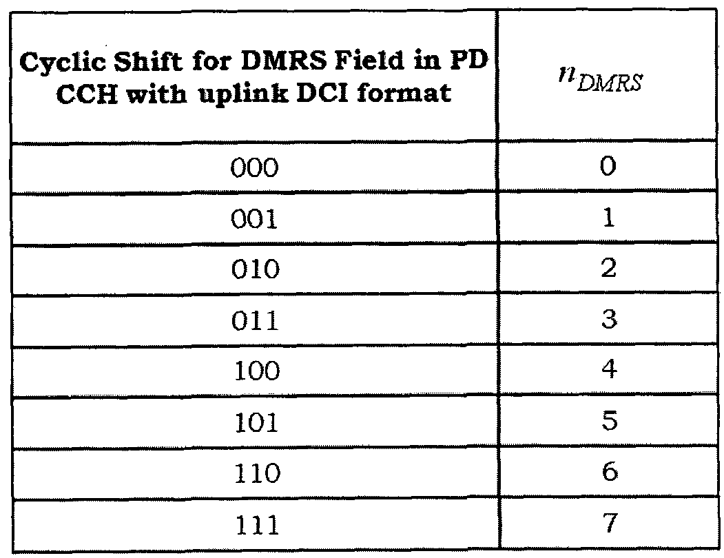
4. 하향링크 제어 정보 송수신 방법 장치 -타입 통신 (MTC : Machine-Type Co誦 uni cat ion)은 각 단말들이 기지국 간 통신을 수행하거나 혹은 복수의 단말들 간에 통신을 수행하는 것을 의미 한다 .
MTC 장치는 MTC를 위해 PL丽 (Public Land Mobile Network)을 통한 MTC 서버와의 통신 및 /또는 다른 MTC 장치 (들)과의 통신을 위해 설계된 단말을 의미한다. 이와 같은 MTC 장치는 MTC 서버 (들) 및 / 또는 다른 MTC 장치 (들)와 통신하며 프로세싱하기 위한 원시 데이터 (raw data)를 MTC 장치에 제공하는 다른 개체와 국부적으로 무선 (예를 들어, PAN(Personal Area Network)) 혹은 고정 배선 (hardwired)을 이용하여 통신할 수도 있다.
하나의 셀 경계 안에서는 이와 같은 MTC를 통한 데이터 전송이 광범위하게 이루어지며 많은 단말들이 위치할 수 있고, 각 단말의 특성 (예를 들어, 넁장고, 세탁기, 휴대폰, TV, 노트북 등)으로 인하여 데이터 전송의 주기 및 전송 데이터의 양이 각각 다른 형태로 구성될 수 있다. 이와 같은 단말들의 특성은 단말의 구현 측면에서 아래 표 14와 같이 카테고리로 구분되어 각 단말들이 설계될 수 있다.
표 14는 카테고리로 별로 요구되는 단말의 성능을 나타낸다.
【표 14]

표 14를 참조하면, 단말 카테고리 (UE category) 1은 요구되는 데이터 율 (data rate)이 적은 경우를 위한 단말들로 구성되고, 이러한 단말들은 다중
입출력 (MIMO)을 지원하지 않으며 단말 내의 버퍼 (buffer) 크기 혹은 메모리 크기가 작거나 간단한 수신 알고리즘을 사용하여 저가로 설계될 수 있다. 반면, 카테고리 8과 같은 경우에는 높은 데이터 율을 요구하므로, 이러한 단말들은 MIM0를 지원하고 큰 버퍼 크기 혹은 메모리 크기를 필요로 하므로 설계를 위해 고가의 부품이 필요하게 된다.
최근 MTC에서는 적은 데이터 양 및 /또는 제한된 이동성 및 /또는 위와 같은 저 비용 장치 카테고리들과 관련하여 설계 비용 절감과 복잡도 감소가 요구된다. 이러한 장치들은 상술한 단말 카테고리 1 보다 더 낮은 복잡도와 적은 비용을 가지고 구현이 가능한 장치들을 의미하며, 이러한 장치들은 MTC의 보급화와 효율적인 운영을 위해 필요하다.
한편, 상술한 바와 같이 단말은 PDCCH를 수신하여 하향링크 제어 정보를 획득하기 위해 블라인드 디코딩 (blind decoding)을 수행한다. 블라인드 디코딩은 PDCCH 내의 모든 CCE를 집합 레벨 (aggregation level) 별로 채널 디코딩을 수행하고, CRC 체크를 통해 단말에게 전송된 DCI 포맷을 검출하는 것을 의미한다. 또한, 단말은 모니터링해야 하는 모든 DCI 포맷에 대하여 블라인드 디코딩을 시도하게 된다.
캐리어 병합 환경을 지원하지 않는 시스템 (non— CA based system)의 경우 하나의 서브프레임 상에서 단말은 공용 서치 스페이스 (CSS)에서 12번의 채널 디코딩을 수행하고, 단말 특정 서치 스페이스 (USS)에서 32번의 채널 디코딩을 수행하여 자신에게 전송된 하향링크 자원 할당 (DL assignment)과 상향링크 자원 할당 (UL grant)를 수신할 수 있다. 또한, 캐리어 병합 환경을 지원하는 시스템 (CA based system)에서는 하향링크 세컨더리 컴포넌트 캐리어 (SCC:
secondary CC)과 상향링크 MIMO가 설정된 상향링크 컴포넌트 캐리어 (CC)의 개수에 따라 '44 + (32 X 하향링크 SCC의 개수) + (16 x 상향링크 MIMO CC의 개수)' 번의 블라인드 디코딩을 수행한다.
따라서, 단말에 설정된 컴포넌트 캐리어의 개수가 증가할수록 블라인드 디코딩 횟수도 선형적으로 증가하게 되며, 이는 결국 단말의 구현에 부담으로 작용하게 된다. 이때, 캐리어 병합 환경을 지원하지 않는 시스템에서의 블라인드 디코딩은 터보 디코딩 (turbo decoding)의 복잡도와 유사하게 작용할 수 있다. 이와 같은 블라인드 디코딩의 횟수는 아래와 같이 크게 3가지 요인으로 결정될 수 있다.
1) 모니터링 해야 하는 CCE 집합 레밸의 총 개수 - CCE 집합 레벨은 신뢰성 있는 PDCCH 전송을 위한 부호율 (code grate)에 따라 결정된다. 따라서, 이는 성공적인 PDCCH 디코딩에 영향을 미칠 수 있으므로 블라인드 디코딩 횟수를 감소시키기 위해 CCE집합 레벨을 제한하기는 쉽지 않다.
2) 모니터링 해야 하는 PDCCH 후보들의 총 개수 - PDCCH 후보들의 총 개수를 제한하는 것은 컴포넌트 캐리어들의 서치 스페이스의 부분 분할 (sub¬ division)의 하나의 형태로 이용함으로써 블라인드 디코딩의 횟수를 감소시킬 수 있는 방법이 될 수 있다. 다만, 이에 의하여 PDCCH 블락킹 (blocking) 가능성을 증가시킬 수 있다.
3) 디코딩해야 하는 DCI 포맷들의 총 개수 ― DCI 포맷 크기 적웅 (adaptation)은 블라인드 디코딩 횟수를 감소시키는 방법 중의 하나이다. DCI 포맷 크기가 적웅된다는 가정하에 DCI 포맷은 공용 서치 스페이스에서 전송된다. 캐리어 특정 서치 스페이스가 정의되는 경우, DCI 포맷 크기 적웅은
블라인드 디코딩 횟수를 감소시키는 관점에서 이득이 되지 않을 수 있다.
상술한 바와 같이, MTC에서의 저 비용 장치를 구현하기 위해서는 블라인드 디코딩의 횟수를 감소시키는 것이 중요하게 작용할 수 있다. 따라서, 본 발명에서는 저 비용 장치를 구현하기 위하여 블라인드 디코딩의 횟수를 즐이기 위한 방법을 제안한다.
도 8은 본 발명의 일실시예에 따른 하향링크 제어 정보를 수신하는 방법올 나타내는 도면이다.
도 8을 참조하면, 기지국은 단말의 성능에 따라 하향링크 제어 정보의 송수신과 관련하여 제한을 설정한다 (S801). 즉, 기지국은 S801 단계에서 확인한 단말의 성능이 앞서 예시한 표 14에서 특정 카테고리에 속하거나 특정 카테고리 보다 낮은 성능을 가지는 경우에, 해당 단말이 하향링크 제어 정보를 수신하기에 적합하도록 하향링크 제어 정보의 송수신과 관련하여 제한들을 설정한다. 이때, 단말의 성능은 표 14에서 단말의 성능을 나타내는 파라미터들과 관련하여 미리 설정된 임계값들을 이용하여 결정될 수 있다.
단말은 기지국으로부터 상위계층 시그널링, 방송 메시지 또는 협상 과정에서의 메시지 등을 통해 해당 단말의 성능에 따른 하향링크 제어 정보를 송수신과 관련하여 설정된 정보를 수신한다 (S803). 이때, 기지국은 단말로부터 전송되는 상위 계층 시그널링을 통해 단말의 성능 (capacity/performace)을 확인할 수 있으며 또는 단말과의 협상 과정 등을 통해 단말의 성능을 확인할 수 있다.
여기서, 하향링크 제어 정보의 송수신과 관련된 설정 정보에는 하향링크 제어 정보의 전송에 이용되는 CCE의 집합 레벨의 범위, 각 CCE 집합 레벨 별
PDCCH 후보 (candidate)들의 개수, 단말에 설정되는 전송 모드의 범위에 대한 정보, 단말에 설정되는 자원 할당 타입의 범위에 대한 정보, 각 서치 스페이스에서 전송되는 DCI 포맷에 대한 정보, 단말에 전송되는 DCI 포맷의 범위에 대한 정보 등이 포함될 수 있다. 이처럼 저 비용 단말을 구현하기 위하여 특히, 블라인드 디코딩 횟수를 감소시키기 위하여 하향링크 제어 정보의 송수신과 관련하여 기존의 설정올 제한하는 방법은 이하 (4. 1) 내지 (4. 8)에서 상세히 설명한다.
또한, 이러한 하향링크 제어 정보와 관련되어 제한적으로 설정되는 정보들은 기지국과 단말 간 미리 설정되어 있올 수 있다. 이러한 경우, 상술한 S801 내지 S803 단계는 생략될 수 있다.
단말은 기지국으로부터 전송되는 PDCCH를 검색하기 위하여 블라인드 디코딩을 수행하고 (S803), 검색된 PDCCH를 통해 전송되는 하향링크 제어 정보를 획득한다 (S805). 이 경우, 단말은 상술한 하향링크 제어 정보의 송수신과 관련하여 설정된 제한들에 따라 블라인드 디코딩을 수행할 수 있다.
이하, 저 비용의 MTC 단말을 구현하기 위해 블라인드 다코딩의 횟수를 줄임으로써, MTC 단말이 PDCCH를 획득하기 위하여 블라인드 디코딩에 필요한 구현 부담을 줄이기 위한 방법들을 설명한다. 이하 (4. 1.) 내지 (4. 7J에서 설명하는 각 방법들은 각각 독립적으로 이용될 수 있으며, 하나 이상의 방법이 조합 (또는 결합)되어 이용될 수도 있다. 또한, 본 발명의 실시예에서는 설명의 편의를 위해 저 비용 장치를 'MTC 단말'로 통칭하여 설명하나, MTC를 위한 단말들에게만 본 발명이 한정되는 것은 아니다.
4. 1. CCE집합 레벨 (aggregation lever) 제한
기존의 단말들은 아래 표 15와 같이 공용 서치 스페이스 혹은 단말 서치 스페이스에 따라 CCE 집합 레벨 별로 블라인드 디코딩을 수행한다.
표 15는 서치 스페이스에 따른 기존의 CCE 집합 레벨을 나타낸다.
15]

MTC 단말을 구현하기 위해서 CCE 집합 레벨을 제한함으로써 블라인드 디코딩 횟수를 즐일 수 있다. 이러한 제한 방법을 통해 아래 표 16과 같이 기존의 CCE 집합 레벨에서 일부분만으로 블라인드 디코딩을 수행하도록 변경할 수 있다.
표 16은 CCE 집합 레벨을 제한하는 예시를 나타낸다.
16】

표 16을 참조하면, 공용 서치 스페이스에서는 CCE 집합 레벨을 4로 제한하고, 단말 특정 서치 스페이스에서는 CCE 집합 레벨은 1, 2로 제한할 수
있다. 즉, 단말은 CCE 집합 레벨 4로 공용 서치 스페이스를 모니터링하고, CCE 집합 레벨들 1, 2의 각각으로 단말 특정 서치 스페이스를 모니터링한다. 결국, CCE 집합 레벨 4인 공용 서치 스페이스에서, 단말은 4개의 PDCCH 후보들에 대해 블라인드 디코딩을 시도한다. 또한, CCE 집합 레벨 1인 단말 특정 서치 스페이스에서 6개의 PDCCH후보들에 대해 블라인드 디코딩을 시도하며 , CCE 집합 레벨 2인 단말 특정 서치 스페이스에서 4개의 PDCCH 후보들에 대해 블라인드 디코딩을 시도한다.
다만, 제안하는 기법은 위의 예와 같이 공용 서치 스페이스와 단말 특정 서치 스페이스 모두를 특정의 CCE 집합 레벨로 제한할 수 있으나, 공용 서치 스페이스와 단말 특정 서치 스페이스 중에서 어느 하나의 서치 스페이스만을 특정의 CCE 집합 레벨로 제한할 수도 있다. 또한, 각 서치 스페이스에서 표 16에서 예시된 것과 상이한 CCE 집합 레벨로 제한할수 있음은 물론이다.
4. 2. PDCCH후보 (candidate)들의 개수제한
MTC 단말을 구현하기 위해서 해당 단말에게 전송하는 PDCCH는 PDCCH후보의 개수를 작게 설정하여 전송함으로써, 블라인드 디코딩 횟수를 줄일 수 있다. 기존의 단말이 각 서치 스페이스에서 각 CCE 집합 레벨 별로 블라인드 디코딩을 수행하는 PDCCH 후보의 개수는 위의 표 15와 같다. 다만, MTC 단말의 블라인드 디코딩의 횟수를 감소시키기 위하여 PDCCH 후보의 개수를 감소시킬 수 있다ᅳ 이러한 방법을 통해 아래 표 17과 같이 각 CCE 집합 레벨에 대한 PDCCH 후보의 개수를 반으로 설정할 수 있다.
표 17은 PDCCH후보의 개수를 제한하는 예시를 나타낸다.
【표 17]
Search space S^L) Number of PDCCH
Type Aggregation level L Size [in CCEs] candidates (i)
1 6 3
UE- 2 12 3
specific 4 8 1
8 16 1
4 16 2
Common
8 16 1 표 17을 참조하면, CCE 집합 레벨 별로 각 서치 스페이스에서 단말이 블라인드 디코딩을 수행하는 PDCCH 후보들의 총 개수를 절반으로 감소시킬 수 있다.
서치 스페이스가 표 17과 같이 구성되는 경우, 제한된 PDCCH 후보들에 따른 서치 스페이스는 다음과 같은 수학식 4에 의해 결정될 수 있다. 즉, 단말은 아래 수학식 4를 통해 서치 스페이스를 규정하고 블라인드 디코딩을 수행할 수 있다. 【수학식 4】
 여기서 , 、 는 k번째 서브프레임의 제어 영역 내에 총 CCE의 개수를 의미하고, i 는 각 PDCCH 후보들에서 개별 CCE를 지정하는 인덱스로서 / = 0,ᅳᅳ-, ^ᅳ1 이다. 또한, L은 집합 레벨을 나타내고, ^e{l,2,4,8}와 같다ᅳ
용 서치 스페이스의 경우, »¾' = /"와 같다. 여기서, »ί = 0,···,Μ("-1이며,
M( "은 서치 스페이스에서 모니터하기 위한 CCE 집합 레벨 L에 따른 PDCCH 후보들의 개수를 나타낸다. 단말 특정 서치 스페이스의 경우, PDCCH가 모니터링되는 서빙 셀에서는 모니터링하는 단말에 캐리어 지시자 필드 (CIF)가 설정되어 있으면, b와 같다. 여기서, lc는 캐리어 지시자 필
값을 나타낸다. 반면, 캐리어 지시자 필드가 설정되지 않으면, ' = ^와 같다. 즉, MTC 단말이 캐리어 병합 (CA) 환경을 지원하지 않는 경우, MTC 단말은 아래 수학식 5에 의해 서치 스페이스를 규정하고 블라인드 디코딩을 수행할 수 있다. 【수학식 51
L {(Yk+ w)mod |_NCCEA IL\}+i
수학식 4 내지 5에서, 공용 서치 스페이스의 경우 2개의 집합 레벨, L=4 및
L=8에 대해 1 ^는 0으로 설정된다. 반면, 집합 레벨 L에 대해 단말 특정 서치 스페이스의 경우 는 아래 수학식 6과 같이 정의된다.
【수학식 61

여기서, -i ="R Ti≠0와 같으며, "RNTI ¾ 위해 사용되는 RNTI 값은 3GPP LTE/LTE-A 시스템에서의 정의를 따를 수 있다. 또한, = 39827 이고, D = 65537 이며, = L"S/2J 와 같다. 여기서, ^ 는 무선 프레임에서 슬롯 번호 (또는 인텍스)를 나타낸다.
한편, 제안하는 기법은 위의 예와 같이 PDCCH 후보들의 개수를 기존에 비하여 절반으로 제한할 수 있으나, 이에 한정되는 것은 아니며 표 17에서 예시된 것과 상이한 PDCCH 후보들의 개수로 제한할 수 있음은 물론이다. 예를 들어, PDCCH 후보들의 개수를 다른 비율 (예를 들어, 1/3 등)으로 제한할 수도 있으며 혹은 기지국과 단말 간에 미리 설정된 특정 개수만큼으로 제한할 수도 있다.
4. 3. 전송 모드 제한
3GPP LTE-A Rel-10 시스템에서의 단말의 경우, 아래 표 18에서와 같이 전송
모드를 가질 수 있으며, 단말에 설정된 전송 모드에 따른 DCI 포맷을 수신한다. 표 18은 전송 모드와 이에 따른 DCI 포맷을 나타낸다.
18]

다만, MTC 단말의 경우 적은 데이터 양의 송수신만을 요구할 수 있으며, 저가의 수신 칩셋 (chipset) 혹은 간단한 구조의 설계를 목표로 하므로 MIM0 송수신 (transmit/receive)를 위한 물리적언 안테나를 사용하지 않을 수 있다. 즉 기존의 단말에 비하여 송수신 안테나가 제한될 수 있으며, 이에 따라 MTC 단말의 경우 전송 모드가 제한될 수 있으며, 이에 따른 DCI 포맷도 제한될 수 있다. 예를 들어, MTC 단말의 전송 모드는 아래 표 19와 같이 안테나의 개수가 한 개인 경우로 한정될 수 있으며, 또한 이때 사용되는 DCI 포맷도 제한적으로 구성될 수 있다.
표 19는 제한된 전송 모드와 이에 따른 DCI 포맷의 예시를 나타낸다.
【표 191
 또한, 아래 표 20과 같이, 수신단의 구현이 비교적 용이하며 수신 SNR(Signal to Noise Ratio)을 높일 수 있는 전송 다이버시티 (Transmit Diversity), 폐루프 랭크 = 1 프리코딩 또는 단일 레이어 범포밍 (beamforming)과 같은 전송 모드도 함께 적용할 수도 있다.
표 20은 제한된 전송 모드와 이에 따른 DCI 포맷의 다른 예시를 나타낸다. 【표 201

이처럼, 제약된 전송 모드가 적용되는 경우 해당 단말은 다중 안테나 (multi antenna)와 연관된 전송 모드와 이에 대한 DCI 포맷을 기대하지 않으므로 좀 더 용이한 구현이 가능할 수 있다. 예를.들어, 단말이 DCI 포맷 2, 2A, 2B, 2C올 수신하는 경우에 관한 절차의 정의 및 구현이 필요 없게 된다.
한편, 제안하는 기법은 위의 예와 같이 전송 모드를 제한할 수 있으나, 이에 한정되는 것은 아니며 표 19 내지 표 20에서 예시된 것과 상이한 전송 모드로 제한할 수 있음은 물론이다.
4. 4. 자원 할당타입 (Resource Allocation Type) 제한
3GPP LTE/LTE-A Rel-8,9,10 시스템에서의 PDSCH의 자원 할당 (RA: resource allocation)은 타입 으 1, 2로 구성되며, 각 자원 할당 타입에 따라 단말이 수신을 기대하는 DCI 포맷은 아래 표 21과 같다.
표 21은 각 자원 할당 타입에 따른 DCI 포맷을 나타낸다.
【표 21]

반면, MTC 단말을 위하여 사용되는 자원 할당 타입을 제한함으로써, MTC 단말의 블라인드 디코딩 횟수를 감소시킬 수 있다. 즉, 자원 할당 타입은 0, 1, 2 중 어느 하나의 자원 할당 타입만을 사용하도록 제한할 수 있다. 또한, 자원 할당 타입 0과 1은 동일한 DCI을 사용하므로 자원 할당 타입 0과 1을 사용하도록 고정될 수도 있다. .
구체적으로, 다시 표 18을 참조하면, 상술한 바와 같이 DCI 포맷 0과 1A는 동일한 크기를 가지므로 각 전송 모드 별로 단말은 DCI 포맷 2개에 대한 블라인드 디코딩을 수행할 수 있다. 다만, 자원 할당 .타입이 0 또는 1로 고정되거나 자원 할당 타입이 2로 고정되는 경우, 단말에게 단말 특정 서치 스페이스로 전송되는 DCI 포맷은 한 가지로 고정될 수 있으며, 결국 단말은 하나의 DCI 포맷에 대한 블라인드 디코딩만을 수행할 수 있어 블라인드 디코딩 횟수를 절반으로 감소시킬 수 있다.
표 22는 제한된 자원 할당 타입과 이에 따른 DCI 포맷의 예시를 나타낸다. 【표 22】
Transmission mode DC I format to be monitored
1. Single-antenna port; port 0 DCM
2.Transmitdiversity DCI1
3. Open-loop spatial multiplexing DC12A
4. Closed-loop spatial multiplexing DCI2
5. Multi-user MiMO DCI1D
6. Closed-loop Rank=1 precoding DCI0/1AorDCI 1B
7. Single-layer beamforming; port 5 DCM
8. Dual-layer beamforming; port 7,8 DCI2B
9. Multi-layer beamforming: port 7-14 DCi2C 표 22를 참조하면, 자원 할당 타입이 0 또는 1로 고정된 경우를 예시하며, 이에 따라 MTC 단말에게 단말 특정 서치 스페이스로 전송되는 DCI 포맷은 한 개로 고정될 수 있다. 다만, 전송 모드 6의 경우 자원 할당 타입 2로만 이루어진 DCI 포맷을 사용하므로 표 22에서와 같이 예외로 처리할 수 있다. 결국, 단말 특정 서치 스페이스에서 전송되는 DCI 포맷이 한 개로 고정 (전송 모드 6 제외)됨으로써, 단말 특정 서치 스페이스에서의 블라인드 디코딩의 횟수를 절반으로 감소시킬 수 있다. 또한, 상향링크 자원 할당 정보는 항상 공용 서치 스페이스로 전송 될 수 있다.
또한, 아래 표 23 내지 표 24와 같이 MTC 단말에 MIM0 송수신이 제한되고 이와 함께 자원 할당 타입이 2로 고정될 수 있다.
표 23은 제한된 전송 모드 및 자원 할당 타입과 이에 따른 DCI 포맷의 예시를 나타낸다.
【표 23]
Transmission mode DC I format to be monitored
1. Single-antenna port; port 0 DCI 0/1 A
2.Transmitdiversity DCI 0/1 A
6. Closed-loop Rank=1 precoding DCi0/1Aor DCI 1B
7. Single-layer beamforming; port 5 DCI 0/1 A 표 24는 제한된 전송 모드 및 자원 할당 타입과 이에 따른 DCI 포맷의 다른 예시를 나타낸다.
【표 24】

이 경우에는, 상향링크 자원 할당 (UL grant)과 하향링크 자원 할당 (DL assignment)가 공용 서치 스페이스 혹은 단말 특정 서치 스페이스에서 전송될 수 있다.
이처럼, 전송 모드 및 자원 할당 타입을 함께 제한함으로써 MTC 단말의 블라인드 디코딩 횟수를 감소시킬 수 있으며, MTC 단말을 저 비용으로 용이하게 구현할 수 있다.
4. 5. 서치 스페이스 (search space) 제한
MTC 단말을 구현하기 위해서 DCI 포맷이 전송되는 서치 스페이스를 제한할 수 있다. 즉, DCI 포맷 별로 전송되는 서치 스페이스를 제한할 수 있으며, 전체 DCI 포맷에 대하여 공용 서치 스페이스와 단말 특정 서치 스페이스 중 어느 하나에서의 전송을 제한할 수도 있다.
구체적으로, 상향링크 자원 할당 (UL grant)는 공용 서치 스페이스로만 전송하고, 각 전송 모드에 해당하는 DCI 포맷은 단말 특정 서치 스페이스로
전송할 수 있다. 또한, 기지국은 채널 상황이 나빠지는 이유 등으로 일정 구간 동안 전송 모드에 해당하는 DCI 포맷을 전송하지 않고 DCI 1A을 전송하는 것을 DCI 1A 폴백 (fall-back)이라 하며, MTC 단말의 경우에 이러한 DCI 1A 폴백을 제한하는 경우 아래 표 25와 같이 나타낼 수 있다.
표 25는 DCI 포맷이 전송되는 서치 스페이스를 제한하는 예시를 나타낸다. 【표 25]

표 25을 참조하면, DCI 포맷을 상향링크 자원 할당 (UL grant)와 하향링크 자원 할당 (DL assignment)를 기준으로 전송되는 서치 스페이스를 구분한 예시를 나타낸다.
또한, 반대로 서치 스페이스를 구분할 수도 있으며, 이는 아래 표 26과 같다.
표 26은 DCI 포떳이 전송되는 서치 스페이스를 제한하는 다른 예시를 나타낸다.
【표 26】
Transmission mode DCI format to be monitored
CSS uss
(DL assignment) (UL grant)
1. Single-antenna port; port 0 DC11 A DCIO
2. Transmit diversity DCMA DCIO
3. Open-loop spatial multiplexing DC11A DCIO
4. Closed-loop spatial multiplexing DCMA DCIO
5. Multi-user MIMO DCI1A DCIO
6. Closed-loop Rank=1 precoding DCI1A DCIO
7. Single-layer beamforming; port 5 DCI1A DCIO
8. Dual-layer beamforming; port 7,8 DCI1A DCIO
9. Multi-layer beamforming: port 7-14 DCMA DCIO 표 26을 참조하면, 하향링크 자원 할당 (DL assignment)를 공용 서치 스페이스를 통해 전송하고, 상향링크 자원 할당 (UL grant)을 단말 특정 서치 스페이스를 통해 전송하는 예를 나타낸다.
또한, 공용 서치 스페이스와 단말 특정 서치 스페이스 중 어느 하나에서 DCI 포맷의 전송을 제한할 수도 있다.
표 27은 DCI 포맷이 전송되는 서치 스페이스를 제한하는 다른 예시를 나타낸다.
【표 27]
Transmission mode DCI format to be monitored
CSS USS
(DL assignment)
(UL grant)
1. Single-antenna port; port 0 - DCI 0/1 A, DCI 1
2. Transmit diversity - DCI 0/1 A, DC1 1
3. Open-loop spatial multiplexing - DCI 0/1 A, DCI 2A
4. Closed-loop spatial multiplexing - DCI 0/1 A, DCI 2
5. Multi-user MIMO - DCI 0/1 A, DCI 1 D
6. Closed-loop Rank=1 precoding - DCI 0/1 A, DCI 1B
7. Single-layer beamforming; port 5 - DCI 0/1 A, DC1 1
8. Dual-layer beamforming; port 7,8 - DCI 0/1 A, DCI 2B
9. Multi-layer beamforming: port 7-14 - DCI 0/1 A, DCI 2C 표 27을 참조하면, 공용 서치 스페이스를 제한한 예시를 나타내며, 상향링크 자원 할당 (UL grant )과 하향링크 자원 할당 (DL assignment ) 모두 단말 특정 서치 스페이스를 통해 전송될 수 있다.
이처 럼, DCI 포맷이 전송되는 서치 스페이스를 제한함으로써 단말이 기대하는 흑은 모니터 링 해야 하는 DCI 포맷의 수가 감소되어 해당 단말의 블라인드 디코딩의 횟수를 감소시킬 수 있다 .
4. 6. DCI 포맷 제한
MTC 단말을 구현하기 위해 해당 단말에 게 전송되는 DCI 포맷을 제한할 수 있다 . 예를 들어, MTC 단말의 공용 서치 스페이스에서 의 블라인드 디코딩 횟수를 감소시 키 기 위하여 그룹 파워 제어를 수행하지 않을 수 있다 . 구체적으로, 이는 TPC-PUCCH-RNTI 흑은 TPC-PUSH— RNTI로 CRC에 스크램블되는 DCI format 3, 3A는 해당 단말들에게 전송하지 않는 것을 의미할 수 있으며 또한 해당 단말들은 DCI format 3, 3A를 모니터 링하지 않는다는 것을 의미할 수 있다 . 따라서, MTC
단말이 공용 서치 스페이스에서 모니터링 해야 하는 DCI 포맷은 DCI 포맷 0/1A로 한정될 수 있다. 결국 DCI 포맷 0과 1A는 페이로드 크기가 동일하므로 공용 서치 스페이스에서 해당 단말은 한 번의 블라인드 디코딩으로 상향링크 자원 할당 (UL grant) 흑은 하향링크 자원 할당 (DL assignment)를 획득할 수 있다.
4. 7. SPS(Semi-Persi stent Scheduling) 기간 (session) 동안 블라인드 디코딩 제한
MTC 단말을 구현하기 위해, MTC 단말의 경우, SPS 기간 동안 블라인드 디코딩을 제한할 수 있다. 즉, MTC 단말이 SPS가 활성화 되면 비활성화 (혹은 해제)될 때까지의 SPS 기간 (session)에 속하는 서브프레임에서는 블라인드 디코딩을 수행하지 않도록 제한할 수 있다. 따라서 해당 단말은 SPS 기간의 서프프레임에서 블라인드 디코딩을 위한 파워를 감소시킬 수 있다.
4. 8. 적용예
상술한 바와 같이 앞서 (4. 1.) 내지 (4. 7.)에서 설명한 방법들 중 하나 이상의 방법이 조합될 수 있다.
이하, (4· 1.) 내지 (4. 6.)에서의 방법이 조합 혹은 결합되어 사용되는 예를 설명한다.
MTC 단말이 캐리어 병합 (CA) 환경을 지원하지 않는 경우, 기존에 단말이 DCI 포맷을 획득하기 위하여 수행하는 블라인드 디코딩의 횟수를 살펴보면, 공용 서치 스페이스의 경우 12번 (CCE 집합 레벨 별 PDCCH 후보의 개수 (4+2) x 서로 다른 DCI 포맷 페이로드 사이즈의 개수 (2)) 수행하고, 단말 특정 서치 스페이스의 경우 32번 (CCE 집합 레벨 별 PDCCH 후보의 개수 (6+6+2+2) x 서로 다른 DCI 포맷 페이로드 사이즈의 개수 (2)) 수행하게 된다. 이처럼, 총 44번의
블라인드 디코딩을 수행하게 된다.
여기서, 앞서 (4. 1.)에서 제안한 방법을 적용하는 경우, 블라인드 디코딩 횟수가 감소될 수 있다. 이때, 표 16이 적용되는 것을 가정하나, 다른 CCE 집합 레벨이 제한될 수 있음은 물론이다. 이 경우 단말이 DCI 포맷을 획득하기 위하여 수행하는 블라인드 디코딩의 횟수를 살펴보면, 공용 서치 스페이스의 경우 8번 (CCE 집합 레벨 별 PDCCH 후보의 개수 (4) x 서로 다른 DCI 포맷 페이로드 사이즈의 개수 (2)) 수행하고, 단말 특정 서치 스페이스의 경우 24번 (CCE 집합 레벨 별 PDCCH 후보의 개수 (6+6) X 서로 다른 DCI 포맷 페이로드 사이즈의 개수 (2)) 수행하게 된다. 이처럼, 총 32번의 블라인드 디코딩을 수행하게 된다. 또한 이를 기반으로 앞서 (4. 2.)에서 제안한 방법을 적용하는 경우, 블라인드 디코딩 횟수가 더 감소될 수 있다. 이때, 표 17이 적용되는 것을 가정하나, PDCCH 후보의 개수를 상이하게 제한할 수 있음은 물론이다. 이 경우 단말이 DCI 포맷을 획득하기 위하여 수행하는 블라인드 디코딩의 횟수를 살펴보면, 공용 서치 스페이스의 경우 4번 (CCE 집합 레벨 별 PDCCH 후보의 개수 (2) X 서로 다른 DCI 포맷 페이로드 사이즈의 개수 (2)) 수행하고, 단말 특정 서치 스페이스의 경우 12번 (CCE 집합 레벨 별 PDCCH 후보의 개수 (3+3) x 서로 다른 DCI 포맷 페이로드 사이즈의 개수 (2)) 수행하게 된다. 이처럼, 총 16번의 블라인드 디코딩을 수행하게 된다.
또한, 이를 기반으로 앞서 (4. 3.)에서 제안한 방법올 적용하는 경우, 다중 안테나 (mult i antenna)와 연관된 전송 모드와 이에 대한 DCI 포맷을 기대하지 않으므로 좀 더 용이한 구현이 가능할 수 있다.
또한, 이를 기반으로 (4. 4.) 흑은 (4. 5J에서 제안한 방법을 적용하는
경우, 블라인드 디코딩 횟수가 더 감소될 수 있다. 즉, 단말 특정 서치 스페이스에서 검출해야 하는 DCI 포맷이 1 가지로 고정되므로 블라인드 디코딩 횟수가 더 감소될 수 있다. 이 경우 단말이 DCI 포맷을 획득하기 위하여 수행하는 블라인드 디코딩의 흿수를 살펴보면, 공용 서치 스페이스의 경우 4번 (CCE 집합 레벨 별 PDCCH 후보의 개수 (2) x 서로 다른 DCI 포맷 페이로드 사이즈의 개수 (2)) 수행하고, 단말 특정 서치 스페이스의 경우 6번 (CCE 집합 레벨 별 PDCCH 후보의 개수 (3+3) X 서로 다른 DCI 포맷 페이로드 사이즈의 개수 (1)) 수행하게 된다. 이처럼, 총 10번의 블라인드 디코딩을수행하게 된다. 또한, 이를 기반으로 (4. 6.)에서 제안한 방법을 적용하는 경우, 블라인드 디코딩 횟수가 더 감소될 수 있다. 즉, 공용 서치 스페이스에서 검출해야 하는 DCI 포맷이 1 가지로 고정되므로 블라인드 디코딩 횟수가 더 감소될 수 있다. 이 경우 단말이 DCI 포맷을 획득하기 위하여 수행하는 블라인드 디코딩의 횟수를 살펴보면, 공용 서치 스페이스의 경우 2번 (CCE 집합 레벨 별 PDCCH 후보의 개수 (2) X 서로 다른 DCI 포맷 페이로드 사이즈의 개수 (1)) 수행하고, 단말 특정 서치 스페이스의 경우 6번 (CCE 집합 레벨 별 PDCCH 후보의 개수 (3+3) 서로 다른 DCI 포맷 페이로드 사이즈의 개수 (1)) 수행하게 된다. 이처럼, 총 8번의 블라인드 디코딩을 수행하게 된다.
5. 본 발명이 적용될수 있는장치 일반
도 9는 본 발명의 일 실시예에 따른 무선 통신 장치의 블록 구성도를 예시한다.
도 9를 참조하면, 무선 통신 시스템은 기지국 (90)과 기지국 (90) 영역 내에 위치한 다수의 단말 (100)을 포함한다.
기지국 (90)은 프로세서 (processor, 91), 메모리 (memory, 92) 및 RF부 (radio frequency unit, 93)을 포함한다. 프로세서 (91)는 제안된 기능, 과정 및 /또는 방법을 구현한다. 무선 인터페이스 프로토콜의 계층들은 프로세서 (91)에 의해 구현될 수 있다. 메모리 (92)는 프로세서 (91)와 연결되어, 프로세서 (91)를 구동하기 위한 다양한 정보를 저장한다. RF부 (93)는 프로세서 (91)와 연결되어, 무선 신호를 송신 및 /또는 수신한다.
단말 (100)은 프로세서 (101), 메모리 (102) 및 RF부 (103)을 포함한다. 프로세서 (101)는 제안된 기능, 과정 및 /또는 방법을 구현한다. 무선 인터페이스 프로토콜의 계층들은 프로세서 (101)에 의해 구현될 수 있다. 메모리 (102)는 프로세서 (101)와 연결되어, 프로세서 (101)를 구동하기 위한 다양한 정보를 저장한다. RF부 (103)는 프로세서 (101)와 연결되어, 무선 신호를 송신 및 /또는 수신한다.
메모리 (92, 102)는 프로세서 (91, 101) 내부 또는 외부에 있을 수 있고, 잘 알려진 다양한 수단으로 프로세서 (91, 101)와 연결될 수 있다. 또한, 기지국 (90) 및 /또는 단말 (100)은 한 개의 안테나 (single antenna) 또는 다중 안테나 (multiple antenna)를 가질 수 있다.
이상에서 설명된 실시예들은 본 발명의 구성요소들과 특징들이 소정 형태로 결합된 것들이다. 각 구성요소 또는 특징은 별도의 명시적 언급이 없는 한 선택적인 것으로 고려되어야 한다. 각 구성요소 또는 특징은 다른 구성요소나 특징과 결합되지 않은 형태로 실시될 수 있다. 또한, 일부 구성요소들 및 /또는 특징들을 결합하여 본 발명의 실시예를 구성하는 것도 가능하다. 본 발명의 실시예들에서 설명되는 동작들의 순서는 변경될 수 있다. 어느 실시예의 일부
구성이나 특징은 다른 실시예에 포함될 수 있고, 또는 다른 실시예의 대웅하는 구성 또는 특징과 교체될 수 있다. 특허청구범위에서 명시적인 인용 관계가 있지 않은 청구항들을 결합하여 실시예를 구성하거나 출원 후의 보정에 의해 새로운 청구항으로 포함시킬 수 있음은 자명하다 .
본 발명에 따른 실시예는 다양한 수단, 예를 들어, 하드웨어, 펌웨어 (firmware), 소프트웨어 또는 그것들의 결합 등에 의해 구현될 수 있다. 하드웨어에 의한 구현의 경우, 본 발명의 일 실시예는 하나 또는 그 이상의 ASICs(application specific integrated circuits) , DSPs(digital signal processors) , DSPDs(digital signal processing devices), PLDs (programmable logic devices) , FPGAs(f ield programmable gate arrays) , 프로세서 , 콘트를러, 마이크로 콘트를러, 마이크로 프로세서 등에 의해 구현될 수 있다.
펌웨어나 소프트웨어에 의한 구현의 경우, 본 발명의 일 실시예는 이상에서 설명된 기능 또는 동작들올 수행하는 모듈, 절차, 함수 등의 형태로 구현될 수 있다. 소프트웨어 코드는 메모리에 저장되어 프로세서에 의해 구동될 수 있다. 상기 메모리는 상기 프로세서 내부 또는 외부에 위치하여, 이미 공지된 다양한 수단에 의해 상기 프로세서와 데이터를 주고 받을 수 있다.
본 발명은 본 발명의 정신 및 필수적 특징을 벗어나지 않는 범위에서 다른 특정한 형태로 구체화될 수 있음은 당업자에게 자명하다. 따라서, 상술한 상세한 설명은 모든 면에서 제한적으로 해석되어서는 아니 되고 예시적인 것으로 고려되어야 한다. 본 발명의 범위는 첨부된 청구항의 합리적 해석에 의해 결정되어야 하고, 본 발명의 등가적 범위 내에서의 모든 변경은 본 발명의 범위에 포함된다.
【산업상 이용가능성】
본 발명의 무선 접속 시스템에서 데이터 송수신 방안은 3GPP LTE 시스템에 적용되는 예를 증심으로 설명하였으나, 3GPP LTE 시스템 이외에도 다양한 무선 접속 시스템에 적용하는 것 이 가능하다 .
Claims
【청구의 범위】
【청구항 11
무선 접속 시스템에서 하향링크 제어 정보 (DCI: Downlink Control Information)를 수신하는 방법에 있어서,
단말에 할당된 서치 스페이스에서 상기 단말에 설정된 전송 모드에 따라 블라인드 디코딩을 수행하는 단계; 및
상기 블라인드 디코딩을 통해 검색된 PDCCH(Physical Downlink Control Channel)을 통해 상기 DCI를 수신하는 단계를 포함하되,
상기 전송 모드는 기지국이 지원하는 복수의 전송 모드들에서 상기 단말의 성능에 따라 제한된 복수의 전송 모드들 중 어느 하나로 설정되는, 하향링크 제어 정보 수신 방법 .
【청구항 2】
제 1항에 있어서,
상기 단말에 설정된 자원 할당 타입에 따른 상기 DCI의 포맷을 이용하여 상기 블라인드 디코딩을 수행하되,
상기 자원 할당 타입은 기지국이 지원하는 복수의 자원 할당 타입들에서 상기 단말의 성능에 따라 어느 하나로 설정되는, 하향링크 제어 정보 수신 방법.
【청구항 3】
거 U항에 있어서,
상기 서치 스페이스는 상기 단말의 성능에 따라 단말 특정 서치 스페이스 (UE— specif ic search space)와 공용 서치 스페이스 (common search space) 중 어느 하나로 설정되는, 하향링크 제어 정보 수신 방법.
【청구항 4】
제 1항에 있어서,
상기 DCI의 포맷 별로 단말 특정 서치 스페이스 (UE— specific search space)와 공용 서치 스페이스 (common search space) 중 어느 하나에서만 전송되는, 하향링크 제어 정보 수신 방법 .
【청구항 5】
제 1항에 있어서,
기지국이 지원하는 복수의 DCI의 포맷들에서 상기 단말의 성능에 따라 제한된 복수의 DCI의 포맷만을 이용하여 상기 블라인드 디코딩을 수행하는, 하향링크 제어 정보 수신 방법.
【청구항 6】
제 1항에 있어서,
기지국이 지원하는 복수의 제어 채널 요소 (CCE: Control Channel Element) 집합 레벨 (aggregation level) 중에서 상기 단말의 성능에 따라 제한된 상기 CCE 집합 레벨만을 이용하여 상기 블라인드 디코딩을 수행하되,
상기 CCE는 상기 PDCCH의 전송을 위한 기본 단위인, 하향링크 제어 정보 수신 방법 . -
【청구항 7]
제 1항에 있어서,
상기 서치 스페이스를 구성하는 상기 PDCCH의 후보들 중에서 상기 단말의 성능에 따라 제한된 후보들만을 통해 상기 블라인드 디코딩을 수행하는, 하향링크 제어 정보 수신 방법 .
【청구항 8】
무선 접속 시스템에서 하향링크 제어 정보 (DCI: Downlink Control Information)를 수신하는 단말에 있어서,
무선 신호를 송수신하기 위한 RF(Radio Frequency) 유닛 ; 및
상기 단말에 할당된 서치 스페이스에서 상기 단말에 설정된 전송 모드에 따라 블라인드 디코딩올 수행하고, 상기 블라인드 디코딩을 통해 검색된 PDCCH(Physical Downlink Control Channel)을 통해 상기 DCI를 수신하는 프로세서를 포함하되,
상기 전송 모드는 기지국이 지원하는 복수의 전송 모드들에서 상기 단말의 성능에 따라 제한된 복수의 전송 모드들 중 어느 하나로 설정되는, 단말.
【청구항 9]
제 8항에 있어서, 상기 프로세서는,
상기 단말에 설정된 자원 할당 타입에 따른 상기 DCI의 포맷을 이용하여 상기 블라인드 디코딩을 수행하되,
상기 자원 할당 타입은 기지국이 지원하는 복수의 자원 할당 타입들에서 상기 단말의 성능에 따라 어느 하나로 설정되는, 단말.
【청구항 10]
제 8항에 있어서,
상기 서치 스페이스는 상기 단말의 성능에 따라 단말 특정 서치 스페이스 (UE一 specif ic search space)와 공용 서치 스페이스 (common search space) 중 어느 하나로 설정되는, 단말.
【청구항 11】
제 8항에 있어서,
상기 DCI의 포¾ 별로 단말 특정 서치 스페이스 (UE-specific search space)와 공용 서치 스페이스 (common search space) 중 어느 하나에서만 전송되는, 단말.
【청구항 12】
제 8항에 있어서, 상기 프로세서는,
기지국이 지원하는 복수의 DCI의 포맷들에서 상기 단말의 성능에 따라 제한된 복수의 DCI의 포맷만을 이용하여 상기 블라인드 디코딩을 수행하는, 단말.
【청구항 13】
제 8항에 있어서, 상기 프로세서는,
기지국이 지원하는 복수의 제어 채널 요소 (CCE: Control Channel Element) 집합 레벨 (aggregation level) 중에서 상기 단말의 성능에 따라 제한된 상기 CCE 집합 레벨만을 이용하여 상기 블라인드 디코딩을 수행하되,
상기 CCE는 상기 PDCCH의 전송을 위한 기본 단위인, 단말.
【청구항 14】
제 8항에 있어서, 상기 프로세서는,
상기 서치 스페이스를 구성하는 상기 PDCCH의 후보들 중에서 상기 단말의 성능에 따라 제한된 후보들만을 통해 상기 블라인드 디코딩을 수행하는, 단말.
Priority Applications (2)
| Application Number | Priority Date | Filing Date | Title |
|---|---|---|---|
| EP12800118.7A EP2723009B1 (en) | 2011-06-15 | 2012-06-15 | Method for receiving downlink control information in wireless access system and terminal therefor |
| US14/125,548 US9438399B2 (en) | 2011-06-15 | 2012-06-15 | Method for receiving downlink control information in wireless access system and terminal therefor |
Applications Claiming Priority (2)
| Application Number | Priority Date | Filing Date | Title |
|---|---|---|---|
| US201161497080P | 2011-06-15 | 2011-06-15 | |
| US61/497,080 | 2011-06-15 |
Publications (2)
| Publication Number | Publication Date |
|---|---|
| WO2012173432A2 true WO2012173432A2 (ko) | 2012-12-20 |
| WO2012173432A3 WO2012173432A3 (ko) | 2013-04-04 |
Family
ID=47357627
Family Applications (1)
| Application Number | Title | Priority Date | Filing Date |
|---|---|---|---|
| PCT/KR2012/004754 Ceased WO2012173432A2 (ko) | 2011-06-15 | 2012-06-15 | 무선 접속 시스템에서 하향링크 제어 정보 수신 방법 및 이를 위한 단말 |
Country Status (3)
| Country | Link |
|---|---|
| US (1) | US9438399B2 (ko) |
| EP (1) | EP2723009B1 (ko) |
| WO (1) | WO2012173432A2 (ko) |
Cited By (1)
| Publication number | Priority date | Publication date | Assignee | Title |
|---|---|---|---|---|
| US10009882B2 (en) | 2013-05-12 | 2018-06-26 | Lg Electronics Inc. | Method for receiving system information by MTC device located in cell coverage-expanded area |
Families Citing this family (38)
| Publication number | Priority date | Publication date | Assignee | Title |
|---|---|---|---|---|
| EP2728775B1 (en) | 2011-06-29 | 2021-03-03 | LG Electronics Inc. | Method and apparatus for receiving control information in wireless communication system |
| US9591429B2 (en) | 2012-05-11 | 2017-03-07 | Qualcomm Incorporated | Methods and apparatus for managing machine-type communications |
| CN110247731B (zh) * | 2012-06-30 | 2021-06-01 | 华为技术有限公司 | 下行控制信息传输方法及基站、终端 |
| CN103781177B (zh) * | 2012-10-19 | 2018-10-30 | 株式会社Ntt都科摩 | 一种信息传输方法、装置及基站 |
| CN104769857B (zh) * | 2012-11-01 | 2018-05-22 | Lg 电子株式会社 | 在无线通信系统中支持设备特性的调度组的方法和装置 |
| CN104756571A (zh) * | 2013-10-09 | 2015-07-01 | 华为技术有限公司 | 半静态共享资源调度方法和装置 |
| US9667386B2 (en) | 2013-11-13 | 2017-05-30 | Samsung Electronics Co., Ltd | Transmission of control channel and data channels for coverage enhancements |
| KR102434108B1 (ko) * | 2013-12-18 | 2022-08-19 | 엘지전자 주식회사 | 무선 통신 시스템에서 단말의 신호 송수신 방법 및 이를 위한 장치 |
| WO2016017038A1 (ja) * | 2014-08-01 | 2016-02-04 | 富士通株式会社 | 通信システム、基地局及び通信端末 |
| CN107078863B (zh) | 2014-11-06 | 2020-11-06 | 苹果公司 | 用于mtc的重复传输的提前终止 |
| EP3247061B1 (en) | 2015-01-12 | 2023-03-01 | LG Electronics Inc. | Method for operating user equipment in wireless communication system, and device therefor |
| WO2016122242A2 (ko) * | 2015-01-29 | 2016-08-04 | 엘지전자 주식회사 | 하향링크 제어 정보 수신 방법 및 사용자기기와, 하향링크 제어 정보 전송 방법 및 기지국 |
| RU2678335C1 (ru) | 2015-02-06 | 2019-01-28 | Панасоник Интеллекчуал Проперти Корпорэйшн оф Америка | СПОСОБ БЕСПРОВОДНОЙ СВЯЗИ, eNodeB, И ОБОРУДОВАНИЕ ПОЛЬЗОВАТЕЛЯ |
| US9918344B2 (en) | 2015-04-09 | 2018-03-13 | Intel IP Corporation | Random access procedure for enhanced coverage support |
| GB2542611B (en) * | 2015-09-25 | 2021-03-31 | Tcl Communication Ltd | Wireless communication system devices |
| US9780913B2 (en) * | 2015-10-23 | 2017-10-03 | Telefonaktiebolaget Lm Ericsson (Publ) | Decoding margin estimation |
| US10193656B2 (en) * | 2015-10-30 | 2019-01-29 | Huawei Technologies Co., Ltd. | Systems and methods for adaptive downlink control information set for wireless transmissions |
| US11496872B2 (en) | 2015-11-06 | 2022-11-08 | Qualcomm Incorporated | Search spaces and grants in eMTC |
| CN105657847A (zh) * | 2016-01-08 | 2016-06-08 | 宇龙计算机通信科技(深圳)有限公司 | 信道检测方法、信道检测装置、终端和基站 |
| JP2019083358A (ja) * | 2016-03-17 | 2019-05-30 | シャープ株式会社 | 端末装置、基地局装置、通信方法、および、集積回路 |
| CN107295677B (zh) * | 2016-03-31 | 2023-10-17 | 中兴通讯股份有限公司 | 执行空闲信道评估的反馈方法及装置 |
| KR20170112897A (ko) | 2016-03-31 | 2017-10-12 | 삼성전자주식회사 | 이동 통신 시스템에서의 채널 상태 정보 보고 모드 설정 방법 및 장치 |
| EP3979543A1 (en) * | 2016-03-31 | 2022-04-06 | Samsung Electronics Co., Ltd. | Resource allocation method in wireless communication system, data reception method on basis of same and device for same |
| US10448372B2 (en) * | 2016-08-12 | 2019-10-15 | Motorola Mobility Llc | Method of control channel monitoring for reduced latency operation |
| CN107889216B (zh) * | 2016-09-30 | 2022-04-29 | 中兴通讯股份有限公司 | 数据发送、接收方法及装置、基站、终端 |
| CN108401294B (zh) * | 2017-02-04 | 2021-10-26 | 华为技术有限公司 | 控制信息的发送和接收方法、接入网设备和终端设备 |
| US10986647B2 (en) | 2017-05-04 | 2021-04-20 | At&T Intellectual Property I, L.P. | Management of group common downlink control channels in a wireless communications system |
| CN109428668B (zh) * | 2017-07-20 | 2021-06-22 | 华为技术有限公司 | 一种数据传输的方法及设备 |
| US11457510B2 (en) * | 2017-08-11 | 2022-09-27 | Apple Inc. | Determining and commuicating control information in wireless telecommunication networks |
| US10123322B1 (en) | 2017-09-18 | 2018-11-06 | Qualcomm Incorporated | Transmission of beam switch commands through control channel signaling |
| CN108418657B (zh) * | 2018-02-07 | 2021-06-04 | 广州慧睿思通信息科技有限公司 | 一种lte系统中dci格式和传输模式的判定方法 |
| US11089582B2 (en) * | 2018-04-05 | 2021-08-10 | Huawei Technologies Co., Ltd. | Method and system for downlink control information payload size determination |
| CN110557223A (zh) * | 2018-06-04 | 2019-12-10 | 电信科学技术研究院有限公司 | 一种物理下行控制信道pdcch的检测方法及终端 |
| WO2020146272A1 (en) * | 2019-01-08 | 2020-07-16 | Apple Inc. | Systems and methods for control signaling of uplink transmission for multiple antenna panels |
| US11962407B2 (en) * | 2020-09-24 | 2024-04-16 | Qualcomm Incorporated | Blind decoding counting for repetition-based physical downlink control channel candidates |
| KR20220113025A (ko) * | 2021-02-05 | 2022-08-12 | 삼성전자주식회사 | 무선 통신 시스템에서 스케줄링을 수행하기 위한 방법 및 장치 |
| CN116073948B (zh) * | 2021-11-04 | 2024-10-18 | Oppo广东移动通信有限公司 | 译码方法及装置、终端设备、芯片、存储介质 |
| CN116527204B (zh) * | 2023-06-28 | 2023-10-17 | 新华三技术有限公司 | 下行控制信息传输方法及装置、电子设备 |
Family Cites Families (7)
| Publication number | Priority date | Publication date | Assignee | Title |
|---|---|---|---|---|
| US9344259B2 (en) * | 2007-06-20 | 2016-05-17 | Google Technology Holdings LLC | Control channel provisioning and signaling |
| KR20090083269A (ko) | 2008-01-29 | 2009-08-03 | 엘지전자 주식회사 | 무선 통신 시스템에서 pdcch 검색 방법 |
| KR20100053060A (ko) * | 2008-11-12 | 2010-05-20 | 삼성전자주식회사 | 다중 반송파 전송 방식을 사용하는 무선 통신 시스템에서의상향링크 자원할당을 위한 제어 정보 수신 방법 |
| KR101635864B1 (ko) * | 2009-02-23 | 2016-07-06 | 엘지전자 주식회사 | 다중 반송파 시스템에서 제어채널을 모니터링하는 장치 및 방법 |
| US9705653B2 (en) * | 2009-05-04 | 2017-07-11 | Qualcomm Inc. | Downlink control transmission in multicarrier operation |
| HUE060448T2 (hu) | 2009-06-02 | 2023-02-28 | Blackberry Ltd | Rendszer és eljárás vakdekódolás csökkentésére vivõaggregációhoz és keresési terek véletlen generálásához a vivõindex, RNTI, és alkeret index függvényében |
| KR20110040672A (ko) | 2009-10-12 | 2011-04-20 | 주식회사 팬택 | 무선통신 시스템에서 제어정보 송수신방법 및 장치 |
-
2012
- 2012-06-15 WO PCT/KR2012/004754 patent/WO2012173432A2/ko not_active Ceased
- 2012-06-15 US US14/125,548 patent/US9438399B2/en not_active Expired - Fee Related
- 2012-06-15 EP EP12800118.7A patent/EP2723009B1/en active Active
Non-Patent Citations (2)
| Title |
|---|
| None |
| See also references of EP2723009A4 |
Cited By (3)
| Publication number | Priority date | Publication date | Assignee | Title |
|---|---|---|---|---|
| US10009882B2 (en) | 2013-05-12 | 2018-06-26 | Lg Electronics Inc. | Method for receiving system information by MTC device located in cell coverage-expanded area |
| CN105210321B (zh) * | 2013-05-12 | 2019-06-07 | Lg电子株式会社 | 用于接收下行控制信息dci的方法和装置 |
| US10856277B2 (en) | 2013-05-12 | 2020-12-01 | Lg Electronics Inc. | Method for receiving information by MTC device located in cell coverage-expanded area |
Also Published As
| Publication number | Publication date |
|---|---|
| US20140233470A1 (en) | 2014-08-21 |
| EP2723009B1 (en) | 2020-02-19 |
| US9438399B2 (en) | 2016-09-06 |
| WO2012173432A3 (ko) | 2013-04-04 |
| EP2723009A4 (en) | 2015-04-01 |
| EP2723009A2 (en) | 2014-04-23 |
Similar Documents
| Publication | Publication Date | Title |
|---|---|---|
| EP2706690B1 (en) | Method for transmitting/receiving data in wireless access system and base station for same | |
| US9225503B2 (en) | Method for transmitting/receiving data in wireless communication system and base station for same | |
| US9438399B2 (en) | Method for receiving downlink control information in wireless access system and terminal therefor | |
| EP3437237B1 (en) | User equipments, base stations and methods for pusch transmission | |
| KR102081939B1 (ko) | 기계타입통신을 지원하는 무선 접속 시스템에서 사운딩 참조 신호의 전송을 제어하는 방법 및 장치 | |
| KR102475628B1 (ko) | 무선 통신 시스템에서 무선 신호 송수신 방법 및 장치 | |
| JP6316871B2 (ja) | 信号送受信方法及びそのための装置 | |
| US9397801B2 (en) | Method for transmitting/receiving data in a wireless access system and base station for same | |
| JP6456471B2 (ja) | 非兔許帯域を支援する無線接続システムにおいて伝送機会区間を設定する方法及び装置 | |
| JP6039652B2 (ja) | キャリアアグリゲーションを支援する無線接続システムにおいて伝送タイミングを調整する方法及び装置 | |
| US9398578B2 (en) | Method for receiving downlink signal, and user device, and method for transmitting downlink signal, and base station | |
| CN107079446B (zh) | 在无线通信系统中通过终端发送和接收信号的方法和设备 | |
| WO2013051856A1 (ko) | 무선 접속 시스템에서 번들링 스케줄링 방법 및 이를 위한 장치 | |
| KR101812174B1 (ko) | 다중 반송파를 사용하는 무선 통신 시스템에서 제어 정보 전송 방법 | |
| WO2013055128A2 (ko) | 무선 접속 시스템에서 번들링 스케줄링 방법 및 이를 위한 장치 | |
| WO2016006859A1 (ko) | 기기간 통신을 지원하는 무선 접속 시스템에서 릴레이 단말의 d2d 신호 송수신 방법 및 장치 | |
| US20180019836A1 (en) | Method for transceiving shortened physical downlink shared channel in wireless access system supporting unlicensed band, and device supporting same | |
| KR20150082222A (ko) | 무선 통신 시스템에서 제어 정보를 검출하는 방법 및 이를 위한 장치 | |
| WO2015163707A1 (ko) | 비면허 대역을 지원하는 무선 접속 시스템에서 데이터 송수신 방법 및 장치 | |
| KR102273756B1 (ko) | 무선 통신 시스템에서 무선 신호 송수신 방법 및 장치 |
Legal Events
| Date | Code | Title | Description |
|---|---|---|---|
| 121 | Ep: the epo has been informed by wipo that ep was designated in this application |
Ref document number: 12800118 Country of ref document: EP Kind code of ref document: A2 |
|
| WWE | Wipo information: entry into national phase |
Ref document number: 14125548 Country of ref document: US |
|
| NENP | Non-entry into the national phase |
Ref country code: DE |