WO2012173434A2 - 무선 접속 시스템에서 무선 자원 할당 방법 및 이를 위한 장치 - Google Patents
무선 접속 시스템에서 무선 자원 할당 방법 및 이를 위한 장치 Download PDFInfo
- Publication number
- WO2012173434A2 WO2012173434A2 PCT/KR2012/004756 KR2012004756W WO2012173434A2 WO 2012173434 A2 WO2012173434 A2 WO 2012173434A2 KR 2012004756 W KR2012004756 W KR 2012004756W WO 2012173434 A2 WO2012173434 A2 WO 2012173434A2
- Authority
- WO
- WIPO (PCT)
- Prior art keywords
- band
- terminal
- adjacent
- available frequency
- reception
- Prior art date
- Legal status (The legal status is an assumption and is not a legal conclusion. Google has not performed a legal analysis and makes no representation as to the accuracy of the status listed.)
- Ceased
Links
Classifications
-
- H—ELECTRICITY
- H04—ELECTRIC COMMUNICATION TECHNIQUE
- H04W—WIRELESS COMMUNICATION NETWORKS
- H04W16/00—Network planning, e.g. coverage or traffic planning tools; Network deployment, e.g. resource partitioning or cells structures
- H04W16/14—Spectrum sharing arrangements between different networks
-
- H—ELECTRICITY
- H04—ELECTRIC COMMUNICATION TECHNIQUE
- H04W—WIRELESS COMMUNICATION NETWORKS
- H04W52/00—Power management, e.g. Transmission Power Control [TPC] or power classes
- H04W52/04—Transmission power control [TPC]
- H04W52/30—Transmission power control [TPC] using constraints in the total amount of available transmission power
- H04W52/36—Transmission power control [TPC] using constraints in the total amount of available transmission power with a discrete range or set of values, e.g. step size, ramping or offsets
- H04W52/367—Power values between minimum and maximum limits, e.g. dynamic range
-
- H—ELECTRICITY
- H04—ELECTRIC COMMUNICATION TECHNIQUE
- H04W—WIRELESS COMMUNICATION NETWORKS
- H04W72/00—Local resource management
- H04W72/04—Wireless resource allocation
-
- H—ELECTRICITY
- H04—ELECTRIC COMMUNICATION TECHNIQUE
- H04W—WIRELESS COMMUNICATION NETWORKS
- H04W72/00—Local resource management
- H04W72/04—Wireless resource allocation
- H04W72/044—Wireless resource allocation based on the type of the allocated resource
- H04W72/0453—Resources in frequency domain, e.g. a carrier in FDMA
-
- H—ELECTRICITY
- H04—ELECTRIC COMMUNICATION TECHNIQUE
- H04W—WIRELESS COMMUNICATION NETWORKS
- H04W72/00—Local resource management
- H04W72/50—Allocation or scheduling criteria for wireless resources
- H04W72/54—Allocation or scheduling criteria for wireless resources based on quality criteria
- H04W72/541—Allocation or scheduling criteria for wireless resources based on quality criteria using the level of interference
Definitions
- the present invention relates to a wireless access system, and more particularly, to a method and apparatus for supporting radio resource allocation in a wireless access system that supports operation in an unlicensed band.
- IEEE 802.11a and b are described in 2.4. Using unlicensed band at GHz or 5 GHz, IEEE 802.lib provides a transmission rate of 11 Mbps, and IEEE 802.11a provides a transmission rate of 54 Mbps.
- IEEE 802 J g applies Orthogonal frequency-division multiplexing (OFDM) at 2.4 GHz, providing a transmission rate of 54 Mbps.
- IEEE 802.11 ⁇ employs multiple input multiple output-OFDM (MIM0-0FDM), which provides a transmission rate of 300 Mbps for four spatial streams. IEEE 802.11 ⁇ supports channel bandwidths up to 40 MHz, in this case 600 Mbps.
- TV White Space is a frequency allocated to broadcast TV, which includes a UHFOJltra High Frequency (VHF) band and a very high frequency (VHF) band, and operates in a corresponding frequency band.
- VHF UHFOJltra High Frequency
- VHF very high frequency
- the licensed device may include a TV, a wireless microphone, and the like, and the licensed device may also be referred to as a licensed user, an incumbent user, or a primary user.
- Unlicensed devices that want to use the TV WS band must provide protection for licensed devices. Therefore, the unlicensed device must check whether the licensed device occupies the corresponding band in order to obtain available channel information before starting to transmit a signal in the TV WS band.
- the unlicensed device may perform spectrum sensing to determine whether the corresponding band is used by the licensed device.
- Spectrum sensing mechanisms include an energy detection method and a feature detection method.
- the unlicensed device may determine that the licensed device is using the specific channel when the strength of the signal received on the specific channel is greater than or equal to a predetermined value or when a digital TV (DTV) preamble is detected. If it is determined that the licensed device is in use in a channel immediately adjacent to the channel currently being used, the transmission power of the unlicensed device should sometimes be lowered depending on the amount of interference radiated to the adjacent band.
- DTV digital TV
- an unlicensed device in the TV S band relies only on frequency sensing to obtain available channel information
- the unlicensed device may be used for operation in the TV WS band.
- the burden of sensing increases, and the procedure can be delayed.
- an unlicensed device may access a geo-location database through an Internet or private network to obtain channel list information available in the area.
- the geographic location database is a database that stores and manages information on registered licensed devices, channel usage information dynamically changing according to the geographical location and channel usage time of licensed devices.
- An object of the present invention is to provide a method and apparatus for efficiently allocating radio resources to a terminal operating as an unlicensed device in a wireless access system, which preferably supports operation in an unlicensed band. Suggest.
- An aspect of the present invention provides a method for allocating radio resources in a wireless access system supporting a TV White Space (TV WS) band. Allocating an available frequency band not used by a licensed device among the bands to the terminal, and when there is a reception band of another device in an adjacent band of the available frequency band, a portion adjacent to the adjacent band among the available frequency bands
- a method comprising: setting a guard band in a band of A, allocating a radio resource to a terminal in a frequency band excluding a guard band in an available frequency band, and receiving uplink data from the terminal through a radio resource;
- the guard band is determined using the allocation position of radio resources, the amount of radio resources and the transmission power of the terminal.
- a radio frequency (RF) unit and a TV WS band licensed device for transmitting and receiving radio signals are used. Assigns available frequency bands that are not available to the terminal, and if a reception band of another device exists in an adjacent band of the available frequency bands, sets a guard band in a portion of the available frequency bands adjacent to the adjacent band, And a processor for allocating radio resources to the terminal in a frequency band other than the guard band and receiving uplink data from the terminal through the radio resource, wherein the guard band includes a radio resource allocation position, a quantity of radio resources, and a transmission power of the terminal. Is determined using.
- the terminal receives information on whether there is a reception band of the other device in the adjacent band from the terminal or the network.
- the information on whether there is a reception band of another device in the adjacent band received from the terminal indicates whether the power measurement value of the adjacent band belongs to a preset range.
- the guard band is set only in a part of bands adjacent to any one adjacent band of the adjacent adjacent bands of the available frequency band.
- the transmit power of the terminal is the maximum transmit power allowed for the terminal.
- a radio resource can be efficiently allocated to a terminal operating as an unlicensed device in a radio access system, preferably a radio access system supporting operation in an unlicensed band.
- FIG. 1 is a diagram illustrating an example of a configuration of a WLAN system.
- FIG. 2 is a diagram illustrating another example of a configuration of a WLAN system.
- FIG. 3 is a diagram illustrating another example of a configuration of a WLAN system.
- 4 is a diagram illustrating another example of a configuration of a WLAN system.
- FIG. 5 is a diagram for describing physical channels used in a 3GPP LTE system and a general signal transmission method using the same.
- FIG. 6 shows a structure of a radio frame in 3GPP LTE.
- FIG. 7 is a diagram illustrating a resource grid for one downlink slot.
- 10 is a configuration diagram of a general multiple input / output antenna (MIM0) communication system.
- 11 is a view Tosa the channel to receive antenna i in ⁇ ⁇ transmit antennas.
- FIG. 12 illustrates a reference signal pattern mapped to a downlink resource block (RB) pair defined in a 3GPP LTE system.
- RB downlink resource block
- FIG 13 shows an uplink subframe including an SRS symbol.
- FIG. 14 is a diagram illustrating an example of relay node resource partitioning.
- FIG. 15 is a diagram illustrating an example of carrier aggregation used in a component carrier (CC) and an LTE_A system of an LTE system.
- CC component carrier
- LTE_A LTE_A system of an LTE system.
- 16 shows a subframe structure of an LTE-A system according to cross carrier scheduling.
- FIG. 17 illustrates an example of coexistence with another service such as DTV through an available channel in a DTV reception band.
- FIG. 18 illustrates a wireless LAN when a WLAN or LTE / LTE-A service coexists with a DTV service. Or it is a diagram illustrating the effect of interference by LTE / LTE-A transmission.
- 19 is a diagram illustrating an uplink resource allocation method for controlling interference radiated to an adjacent band according to an embodiment of the present invention.
- 20 is a diagram illustrating an example of setting a guard band in an available frequency band according to an embodiment of the present invention.
- FIG. 21 illustrates a block diagram of a wireless communication device according to an embodiment of the present invention.
- FIG. 22 illustrates a processor structure of a base station or a terminal according to an embodiment of the present invention.
- the base station has a meaning as a terminal node of the network that directly communicates with the terminal.
- Certain operations described in the document as being performed by a base station may, in some cases, be performed by an upper node of the base station. That is, it is apparent that various operations performed for communication with a terminal in a network including a plurality of network nodes including a base station may be performed by the base station or other network nodes other than the base station.
- a 'base station (BS)' may be replaced by terms such as a fixed station, a Node B, an eNode B (eNB), an access point (AP), and the like.
- the repeater may be replaced by terms such as relay node (RN) and relay station (RS).
- RN relay node
- RS relay station
- terminal may be replaced with terms such as UE Jser Equiment (MS), Mobile Station (MS), Mobile Subscriber Station (MSS), SSCSubscriber Station (STA), and STA (Station).
- Embodiments of the present invention may be supported by standard documents disclosed in at least one of the IEEE 802 system, the 3GPP system, the 3GPP LTE and the LTE-Advanced (LTE-A) system, and the 3GPP2 system. That is, steps or parts which are not described to clearly reveal the technical spirit of the present invention among the embodiments of the present invention may be supported by the above documents. In addition, all terms disclosed in this document may be described by the above standard document.
- CDMA code division multiple access
- FDMA frequency division multiple access
- TDMA time division multiple access
- OFDMA orthogonal frequency division multiple access
- SC-FDMA single single
- CDMA may be implemented by radio technology such as UTRACUniversal Terrestrial Radio Access) or CDMA2000.
- TDMA may be implemented in a wireless technology such as Global System for Mobile Communications (GSM) / General Packet Radio Service (GPRS) / Enhanced Data Rates for GSM Evolution (EDGE).
- GSM Global System for Mobile Communications
- GPRS General Packet Radio Service
- EDGE Enhanced Data Rates for GSM Evolution
- 0FDMA may be implemented by a wireless technology such as IEEE 802.11 (Wi-Fi), IEEE 802.16 (WiMAX), IEEE 802-20, Evolved UTRA (E-UTRA), or the like.
- UTRA is part of the Universal Mobile 6 (UMTS) ⁇ 1111 ⁇ 10115 System.
- 3rd Generation Partnership Project (3GPP) long term evolution (LTE) is part of Evoided UMTS (E-UMTS) using E-UTRA, and employs 0FDMA in downlink and SC-FDMA in uplink.
- LTE-A Advanced is the evolution of 3GPP LTE.
- FIG. 1 is a diagram illustrating an example of a configuration of a WLAN system.
- a WLAN system includes one or more basic service sets (BSSs).
- a BSS is a set of stations (STAs) that can successfully communicate with each other through synchronization.
- 1 illustrates two BSSs and two STAs connected to each BSS. The oval in FIG. 1 indicates the coverage area of the BSS, which is called a basic service area (BSA). If the STA moves beyond the BSA, the STA can no longer communicate directly with other STAs present in the BSA.
- BSA basic service area
- IBBS Independent BSS
- IBBS Infrastructure BSS
- IBBS is the most basic of WLAN system
- FIG. 1 In IBBS, direct communication between STAs is possible, and such a type of operation between STAs is called an ad hoc network.
- the STA In order to access the BSS, the STA must perform a procedure for synchronizing with the base station. In addition, in order to access all the services of the infrastructure BSS, the STA must be associated with a base station. This linkage procedure is performed dynamically and involves the use of the Distribution System Service (DSS).
- DSS Distribution System Service
- FIG. 2 is a diagram illustrating another example of a configuration of a WLAN system.
- the direct distance that can be supported between the STA and the STA may be physically limited. Depending on the network, this distance may be fragmented, but not so fragmented that an extension of coverage may be required.
- the BSS may be configured as an element in an extended form of a network composed of a plurality of BSSs.
- the architectural element used to interconnect the BSSs is referred to as a distribution system (DS).
- the DS is a mechanism for connecting a plurality of APs.
- the DS does not necessarily need to be a network, and there is no limitation on its form as long as it can provide a predetermined distribution service.
- the DS may be a wireless network such as a mesh network or a physical structure that connects APs to each other.
- a distribution system medium (DSM) and a wireless medium may be logically divided. Each logical medium serves a different purpose by different elements of the architecture.
- DS manages seamless integration of multiple BSSs and address mapping to destinations The mobility of the device is supported by providing the logical services required for this purpose.
- An access point is an entity that supports an associated STA to access a distribution system through a WM. Data is moved between the BSS and the DS through the AP. In this case, since all APs can be STAs, APs are entities having addresses. However, the addresses used by the AP for communication through the network and communication through the DSM need not be the same.
- FIG. 3 is a diagram illustrating another example of a configuration of a WLAN system.
- a DS and a BSS may be used to form a wireless network having an arbitrary size and complexity, and this network type is called an extended service set (ESS) network.
- An ESS means a plurality of BSSs connected through a DS and does not include a DS. Since the ESS network has the same Logical Link Control (LLC) layer as the IBSS network, an STA belonging to an ESS can move from one BSS to another BSS within the same ESS transparently to the LLC. .
- LLC Logical Link Control
- BSSs may be partially overlapped to form physically continuous coverage.
- the BSSs since the logical distance between the BSSs is not limited, the BSSs may not be physically connected.
- BSSs may not be physically combined to avoid unnecessary duplication.
- an IBBS or ESS network when the ad hoc network operates in a location having an ESS network, or when a WLAN system network that is physically overlapped is configured in a different structure, or when a plurality of different access or security policies are required in the same location, Or more) an IBBS or ESS network has one (or more) ESS It can exist in the same physical space as the network.
- FIG. 4 is a diagram illustrating another example of a configuration of a WLAN system.
- the STA is a logical entity that includes Medium Access Control (MAC) and a Physical Layer (Physical Layer) interface to the wireless medium, and includes an AP Stat ion (AP STA) and a non-AP Stat ion (AP STA).
- MAC Medium Access Control
- AP STA AP Stat ion
- AP STA non-AP Stat ion
- AP STA non-AP Stat ion
- a portable terminal operated by a user is a non-AP STA, and when referred to simply as an STA, it may also refer to a non-AP STA.
- a non-AP STA may be a terminal, a wireless transmit / receive unit (WTRU), a user equipment (UE), a mobile station (MS), a mobile terminal, or a mobile subscriber unit. It may also be called another name (Mobile Subscriber Unit).
- the AP is an entity that provides an associated station (STA) coupled to it to access a distribution system (DS) through a wireless medium.
- the AP may be called a centralized controller, a base station (BS), a Node-B, a base transceiver system (BTS), a femto BS, or a site controller.
- FIG. 5 is a diagram for describing physical channels used in a 3GPP LTE system and a general signal transmission method using the same.
- an initial cell search operation such as synchronizing with a base station is performed in step S51.
- the UE transmits a main synchronization channel (P-SCH: Receives a Primary Synchronization Channel and a Secondary Synchronization Channel (S-SCH) to synchronize with the base station and obtain information such as a Sal ID.
- P-SCH Receives a Primary Synchronization Channel and a Secondary Synchronization Channel (S-SCH)
- the terminal may receive a physical broadcast channel (PBCH) signal from the base station to obtain broadcast information in a cell.
- PBCH physical broadcast channel
- the UE may check the downlink channel state by receiving a downlink reference signal (DL RS) in the initial cell search step.
- DL RS downlink reference signal
- the UE After completing the initial cell discovery, the UE receives a physical downlink control channel (PDCCH) and a physical downlink control channel (PDSCH) according to the physical downlink control channel information in step S52. Specific system information can be obtained.
- PDCCH physical downlink control channel
- PDSCH physical downlink control channel
- the terminal may perform a random access procedure as described in steps S53 to S56 to complete the access to the base station.
- the UE transmits a preamble through a physical random access channel (PRACH) (S53), and a response message to the preamble through the physical downlink control channel and the physical downlink shared channel. Can be received (S54).
- PRACH physical random access channel
- the UE performs contention resolution such as transmitting an additional physical random access channel signal (S55) and receiving a physical downlink control channel signal and a corresponding physical downlink shared channel signal (S56). Procedure).
- the terminal which has performed the above-described procedure is then a general uplink / downlink signal transmission procedure for the physical downlink control channel signal and / or the physical downlink shared channel signal.
- a reception S57 and a transmission of a physical uplink shared channel (PUSCH) signal and / or a physical uplink control channel (PUCCH) signal (S58) may be performed.
- PUSCH physical uplink shared channel
- PUCCH physical uplink control channel
- UCI uplink control information
- HARQ-ACK / NACK Hybrid Automatic Repeat and reQuest Acknowledgement / Negative-ACK
- SR Scheduling Request
- CQI Channel Quality Indication
- PMI Precoding Matrix Indication
- RI Rank Indication
- UCI is generally transmitted periodically through the PUCCH, but may be transmitted through the PUSCH when control information and traffic data should be transmitted at the same time.
- the UCI may be aperiodically transmitted through the PUSCH by a request / instruction of the network.
- FIG. 6 shows a structure of a radio frame in 3GPP LTE.
- a radio frame consists of 10 subframes.
- One subframe consists of two slots in the time domain.
- the time taken to transmit one subframe is called a TTKtransmission time interval.
- one subframe may have a length of 1 ms and one slot may have a length of 0.5 ms.
- One slot includes a plurality of orthogonal frequency division multiplexing (0FDM) symbols in the time domain. Since 3GPP LTE uses 0FDMA in downlink, the 0FDM symbol is for representing one symbol period. The 0FDM symbol may be referred to as one SC-FDMA symbol or symbol period.
- resource A resource block is a resource allocation unit and includes a plurality of consecutive subcarriers in one slot.
- the structure of the radio frame is only one example, and the number of subcarriers included in the radio frame, the number of slots included in the subframe, and the number of OFDM symbols included in the slot may be variously changed.
- FIG. 7 is a diagram illustrating a resource grid for one downlink slot.
- one downlink slot includes a plurality of OFDM symbols in the time domain.
- one downlink slot includes seven OFDM symbols and one resource block includes 12 subcarriers in the frequency domain, but is not limited thereto. .
- Each element on the resource grid is called a resource element, and one resource block includes 12 X 7 resource elements.
- the number N DL of resource blocks included in the downlink pilot depends on the downlink transmission bandwidth.
- the structure of the uplink slot may be the same as the structure of the downlink slot.
- up to three OFDM symbols in the first slot in a subframe are control regions to which control channels are allocated, and the remaining OFDM symbols are data regions to which a PDSCH (Physical Downlink Shared Channel) is allocated. data region).
- Examples of downlink control channels used in 3GPP LTE include a physical control format indicator channel (PCFICH), a physical downlink control channel (PDCCH), and a physical hybrid-ARQ indicator channel (PHICH).
- PCFICH is transmitted in the first OFDM symbol of a subframe and carries information about the number of OFDM symbols (ie, the size of the control region) used for transmission of control channels within the subframe.
- the PHICH is a male answer channel for the uplink, and carries an ACK (Acknowledgement) / NACK (Not-Acknowledgement) signal for a hybrid automatic repeat request (HARQ).
- Control information transmitted through the PDCCH is called downlink control information (DCI).
- the downlink control information includes uplink resource allocation information, downlink resource allocation information, or an uplink transmission (Tx) power control command for a certain terminal group.
- PDCCH is a resource allocation and transmission format of DL-SCH (Downlink Shared Channel) (also referred to as a downlink grant), resource allocation information of UL-SCH (Uplink Shared Channel) (this is also called an uplink grant), and PCH ( Paging information in paging channel, system information in DL-SCH, resource allocation for upper-layer control message such as random access response transmitted in PDSCH, arbitrary terminal It can carry a set of transmission power control commands for the individual terminals in the group, activation of VoIPCVoice over IP).
- the plurality of PDCCHs may be transmitted in the control region, and the terminal may monitor the plurality of PDCCHs.
- the PDCCH consists of a collection of one or a plurality of consecutive CCE control channel elements.
- the CCE is a logical allocation unit used to provide a PDCCH with a coding rate according to the state of a radio channel.
- the CCE is referred to a plurality of resource element groups.
- the format of the PDCCH and the number of available bits of the PDCCH are determined according to the association between the number of CCEs and the coding rate provided by the CCEs.
- the base station determines the PDCCH format according to the DCI to be transmitted to the terminal and attaches a CRCCCyclic Redundancy Check to the control information.
- the CRC is masked by a unique identifier (referred to as RNTKRadio Network Temporary Identifier) according to the owner or purpose of the PDCCH.
- RNTKRadio Network Temporary Identifier a unique identifier
- a unique identifier of the terminal may be masked to the CRC.
- a paging indication identifier for example, P-RNTI (P-RNTI) may be masked to the CRC.
- the system information more specifically, the PDCCH for the system information block (SIB), the system information identifier and the system information RNTI (SI-RNTI) may be masked to the CRC.
- SIB system information block
- SI-RNTI system information RNTI
- RA-RNTI random access-RNTI
- an uplink subframe may be divided into a control region and a data region in the frequency domain.
- a control region (PUCCHCPhysical Uplink Control Channel) carrying uplink control information is allocated to the control region.
- the data region is allocated a Physical Uplink Shared Channel (PUSCH) that carries user data.
- PUSCH Physical Uplink Shared Channel
- a PUCCH for one UE is allocated a resource block (RB) pair in a subframe. RBs belonging to the RB pair occupy different subcarriers in each of the two slots. This RB pair allocated to the PUCCH is said to be frequency hopping at the slot boundary (slot boundary).
- MIM0 Multi -Input Multi -Output
- MIMO technology generally uses multiple transmit (Tx) antennas and multiple receive (Rx) antennas away from the ones that generally used one transmit antenna and one receive antenna.
- the MIM0 technology is a technique for increasing capacity or individualizing performance by using multiple input / output antennas at a transmitting end or a receiving end of a wireless communication system.
- MIM0 will be referred to as "multi-input / output antenna”.
- the multi-input / output antenna technology does not rely on one antenna path to receive one total message, and collects a plurality of pieces of data received through several antennas to complete complete data.
- multiple input / output antenna technology can increase the data rate within a specific system range, and can also increase the system range through a specific data rate.
- MIM0 communication technology is the next generation mobile communication technology that can be widely used in mobile communication terminals and repeaters, and attracts attention as a technology that can overcome the transmission limitations of other mobile communication depending on the limit situation due to the expansion of data communication. have.
- MIM0 multiple input / output antenna
- 10 is a configuration diagram of a general multiple input / output antenna (MIM0) communication system: 10, the number of transmission antennas ⁇ ⁇ dogs, received when increased the number of antennas of the open-circuit N R at the same time, the transmitter or only a large number of theoretical channel transmission in proportion to the number of antennas, unlike in the case that will be served by the antenna receiver Since the capacity is increased, it is possible to improve the transfer rate and to significantly improve the frequency efficiency.
- the transmission rate according to the increase in the channel transmission capacity may theoretically increase by multiplying the maximum transmission rate Ro in the case of using one antenna by the following rate increase rate Ri.
- the technique of the multi-input / output antennas is a spatial diversity scheme that improves transmission reliability by using symbols that have passed through various channel paths, and a transmission rate is improved by simultaneously transmitting a plurality of data symbols by using a plurality of transmit antennas. It can be divided into spatial multiplexing method. In addition, researches on how to appropriately combine these two methods to obtain the advantages of each are being studied in recent years.
- the spatial multiplexing technique is a method of transmitting different data streams at each transmitting antenna, and at the receiver, mutual interference occurs between data transmitted simultaneously from the transmitter.
- the receiver removes this interference using an appropriate signal processing technique and receives it.
- the noise cancellation schemes used here include MLDCmaximum likelihood detection (ZDC) receivers, zero-forcing (ZF) receivers, minimum mean square error (MMSE) receivers, U-Diagonal-Bel 1 Laboratories Layered Space-Time (VLAST), and V-BLASTC Vertical. -Be 11 Laboratories Layered Space-Time, etc.
- ZDC maximum likelihood detection
- ZF zero-forcing
- MMSE minimum mean square error
- VLAST U-Diagonal-Bel 1 Laboratories Layered Space-Time
- V-BLASTC Vertical U-Diagonal-Bel 1 Laboratories Layered Space-Time
- VLAST U-Diagonal-Bel 1 Laboratories Layered Space-Time
- the transmission power in each of the transmission information Si, S2, S NT is different, and if each transmission power,? 2, P NT , the transmission power can be represented by the following vector.
- the information vector S whose transmission power has been adjusted is then rapidly weighted to form the ⁇ ⁇ transmission signals, ⁇ 2 ,..., ⁇ ⁇ , which are actually transmitted.
- the weight matrix plays a role of properly distributing transmission information to each antenna according to a transmission channel situation.
- This transmission signal,) 3 ⁇ 4 is used with vector X. It can be expressed as:
- Wij represents a weight between the i th transmit antenna and the j th transmission information.
- W represents this as a matrix.
- Such a matrix W is called a weight matrix or a precoding matrix.
- the above-described transmission signal (X) can be considered divided into the case of using the spatial diversity and the case of using the spatial multiplexing.
- the elements of the information vector s all have different values, while using spatial diversity causes the same signal to be sent through multiple channel paths.
- the elements of the information vector s therefore all have the same value.
- a method of combining spatial multiplexing and spatial diversity is also conceivable. That is, for example, a case may be considered in which the same signal is transmitted by using spatial diversity through three transmission antennas, and the remaining signals are spatially multiplexed by different signals.
- the reception signal is represented by the vector y of the reception signals, y 2 ,..., Yi «of each antenna as follows.
- each channel may be classified according to a transmit / receive antenna index, and a channel passing from the transmit antenna j to the receive antenna i is denoted by. Note that the order of the index of the receiver antenna index first, the index of the transmission antenna later.
- These channels can be grouped together and displayed in vector and matrix form.
- An example of the vector display is described below.
- FIG. 11 is a diagram illustrating a channel from N T transmit antennas to a receive antenna i.
- a channel arriving from the total N T antennas to the reception antenna i may be expressed as follows.
- Equation (7) when all the channels passing through the N R receive antennas from ⁇ ⁇ transmit antennas are represented as shown in Equation (7), they can be expressed as follows.
- each of the multiple input / output antenna communication systems may be represented through the following relationship.
- the rank of a matrix is defined as the minimum number of rows or columns that are independent of each other.
- the rank of the matrix cannot be greater than the number of rows or columns.
- the rank (H) of the channel matrix H is limited as follows.
- the tank when the matrix is subjected to eigen value decomposition, the tank may be defined as the number of eigenvalues that are not zero among eigen values.
- a tank when a tank is singular value decomposition (SVD), it can be defined as the number of non-zero singular values. Therefore, the physical meaning of the tank in the channel matrix is the maximum number that can send different information in a given channel.
- 'Rank' for MIM0 transmission refers to the number of paths that can independently transmit a signal at a specific time point and a specific frequency resource, and 'number of layers' is transmitted through each path.
- the transmitting end since the transmitting end transmits a number of layers corresponding to the number of tanks used for signal transmission, unless otherwise specified, a tank has the same meaning as the number of layers.
- the signal may be distorted during transmission.
- the distortion of the received signal must be corrected using the channel information.
- Channel information In order to detect, a signal transmission method known to both a transmitting side and a receiving side and a method of detecting channel information using a distorted degree when a signal is transmitted through a channel are mainly used.
- the above-mentioned signal is called a pilot signal or a reference signal RS.
- each transmit antenna When transmitting and receiving data using multiple input / output antennas, a channel state between a transmitting antenna and a receiving antenna must be detected in order to receive a signal accurately. Therefore, each transmit antenna must have a separate reference signal.
- the downlink reference signal includes a common reference signal (CRS: common RS) shared by all terminals in one cell and a dedicated reference signal (DRS) for only a specific terminal.
- CRS common reference signal
- DRS dedicated reference signal
- the receiving side measures the channel state from the CRS, and feeds back an indicator related to the channel quality such as the CQKChannel Quality Indicator), the PMK Precoding Matri Index), and / or the RKRank Indicator to the transmitting side (ie, the base station).
- CRS is also referred to as cell-specific RS.
- a reference signal related to CQI / PMI / RI related to feedback of channel state information (CSI) may be defined as CSI-RS.
- the DRS may be transmitted through resource elements when data demodulation on the PDSCH is needed.
- the UE may receive the presence or absence of a DRS through a higher layer and is valid only when a corresponding PDSCH is mapped.
- the DRS may be referred to as a UE-specific RS or a demodulation reference signal (DMRS).
- 12 illustrates a reference signal pattern mapped to a downlink resource block (RB) pair defined in a 3GPP LTE system.
- a downlink resource block pair may be represented by 12 subcarriers in one subframe X frequency domain in a time domain in a unit in which a reference signal is mapped.
- one resource block pair on the time axis has a length of 14 OFDM symbols in case of normal cyclic prefix (normal CP) (FIG. 12 (a)), and an extended cyclic prefix In case of Extended Cyclic Prefix (CP), it has a length of 12 OFDM symbols (FIG. 12 (b)). '0' in the resource block grid
- Resource elements (REs) described as '2' and '3' refer to the position of the CRS at antenna port indexes '0', '1', '2' and '3', respectively. Indicates the location of the DRS.
- the CRS is used to estimate a channel of a physical antenna and is distributed in the entire frequency band as a reference signal that can be commonly received by all terminals located in a cell.
- CRS may be used for channel quality information (CSI) and data demodulation.
- CSI channel quality information
- the CRS is defined in various formats depending on the antenna arrangement at the transmitting side (base station).
- the 3GPP LTE system (eg, Release-8) supports various antenna arrangements, and the downlink signal transmitting side has three types of antenna arrangements such as three single transmit antennas, two transmit antennas, and four transmit antennas. .
- the reference signal for the single antenna port is arranged.
- reference signals for two transmit antenna ports are arranged using time division multiplexing (TDM) and / or FDM frequency division multiplexing (FDM) scheme. That is, the reference signals for the two antenna ports are each distinct Different time resources and / or different frequency resources are allocated for this purpose.
- TDM time division multiplexing
- FDM frequency division multiplexing
- reference signals for the four transmit antenna ports are arranged using the TDM and / or FDM scheme.
- the channel information measured by the receiving side (terminal) of the downlink signal may be transmitted using a single transmit antenna transmission, transmit diversity, closed-loop spatial multiplexing, open-loop spatial multiplexing or It may be used to demodulate data transmitted using a transmission scheme such as a multi-user multi-input / output antenna (Mult i-User MIM0).
- the reference signal when multiple input / output antennas are supported, when a reference signal is transmitted from a specific antenna port, the reference signal is transmitted at a location of resource elements specified according to a pattern of the reference signal and at a location of resource elements specified for another antenna port. Not sent. That is, reference signals between different antennas do not overlap each other.
- mapping CRSs to resource blocks are defined as follows.
- Equation 12 k and 1 represent the subcarrier index and the heartbull index, respectively.
- P is an antenna port. " ⁇ in one downlink slot
- N RB represents the number of radio resources allocated to the downlink.
- n s represents a slot index and N! D represents a cell ID.
- mod stands for modulo operation.
- the position of the reference signal depends on the V shift value in the frequency domain. Since V shif t depends on the cell ID, the position of the reference signal has various frequency shift values depending on the cell.
- the position of the CRS may be shifted in the frequency domain according to sal in order to improve channel estimation performance through the CRS.
- reference signals in one cell are allocated to a 3k th subcarrier, and reference signals in another cell are allocated to a 3k + l th subcarrier.
- the reference signals are arranged at six resource element intervals in the frequency domain, and are separated at three resource element intervals from the reference signal allocated to another antenna port.
- reference signals are arranged at constant intervals starting from symbol index 0 of each slot.
- the time interval is defined differently depending on the cyclic prefix length.
- the reference signal In the case of general cyclic prefix, the reference signal is located at symbol indexes 0 and 4 of the slot, and in the case of extended cyclic prefix, the reference signal is located at symbol indexes 0 and 3 of the slot.
- the reference signal for the antenna port having the maximum of two antenna ports is defined in one OFDM symbol.
- the reference signals for reference signal antenna ports 0 and 1 are located at symbol indices 0 and 4 (symbol indices 0 and 3 for extended cyclic prefix) of slots,
- the reference signal for is located at symbol index 1 of the slot.
- Antenna port The positions in the frequency domain of the reference signal for 2 and 3 are swapped with each other in the second slot.
- DRS is used to demodulate data. Precoding weights used for a specific terminal in multiple I / O antenna transmission are used without change to estimate a channel combined with the transmission channel transmitted from each transmission antenna when the terminal receives the reference signal.
- the 3GPP LTE system (eg, Release-8) supports up to four transmit antennas, and a DRS for tank 1 beamforming is defined.
- the DRS for tank 1 bump forming also indicates the reference signal for antenna port index 5.
- Equation 13 shows a case of a general cyclic prefix
- Equation 14 shows a case of an extended cyclic prefix
- Equations 12 to 14 k and p represent subcarrier indexes and antenna ports, respectively.
- ns denotes the number of downlink RBs, the number of slot indices, and the number of cell IDs.
- RS position in terms of frequency domain
- Equations 13 and 14 k and 1 represent a subcarrier index and a symbol index, respectively, and p represents an antenna port.
- Nsc represents a resource block size in the frequency domain and is represented by the number of subcarriers.
- ' lpRB is the number of physical resources
- Nrb represents a frequency band of a resource block for PDSCH transmission.
- n s represents a frequency band of a resource block for PDSCH transmission.
- N 1D denotes a cell ID
- mod stands for modulo operation.
- the position of the reference signal depends on the V shift value in the frequency domain.
- V sh ift depends on the cell ID
- the position of the reference signal has various frequency shift values depending on the cell.
- CoMP is also called MIMO, collaborative MIMO, network MIMO, etc.
- CoMP is expected to improve the performance of the terminal located at the cell boundary, and improve the throughput of the average cell (sector).
- inter-cell interference reduces performance and average cell (sector) efficiency of a terminal located at a cell boundary in a multi-cell environment having a frequency reuse index of 1.
- a simple passive method such as Fractional Frequency Reuse (FFR) is used in the LTE system so that the UE located at the cell boundary has an appropriate performance efficiency in an interference-limited environment.
- FFR Fractional Frequency Reuse
- a method of reusing inter-sal interference or mitigating inter-cell interference as a signal that the terminal needs to receive is more advantageous.
- CoMP transmission scheme may be applied to achieve the above object.
- CoMP schemes that can be applied to the downlink may be classified into a joint processing (JP) scheme and a coordinated scheduling / beamforming (CS / CB) scheme.
- JP joint processing
- CS / CB coordinated scheduling / beamforming
- data can be used at each point (base station) in CoMP units.
- CoMP unit means a set of base stations used in the CoMP scheme.
- the JP method can be further classified into a joint transmission method and a dynamic cell selection method.
- the associated transmission scheme refers to a scheme in which a signal is simultaneously transmitted through a PDSCH from a plurality of points, which are all or part of a CoMP unit. That is, data transmitted to a single terminal may be simultaneously transmitted from a plurality of transmission points.
- coherently or non-intrusive Coherently can improve the quality of the signal transmitted to the terminal, and can actively remove the interference with another terminal.
- the dynamic cell selection method refers to a method in which a signal is transmitted through a PDSCH from a single point in a CoMP unit. That is, data transmitted to a single terminal at a specific time is transmitted from a single point, and data is not transmitted to the terminal at another point in the CoMP unit.
- the point for transmitting data to the terminal may be dynamically selected.
- the CoMP unit performs coordination for data transmission to a single terminal. That is, although only the serving cell transmits data to the terminal, user scheduling / beamforming may be determined through cooperation between a plurality of cells in a CoMP unit.
- CoMP reception means receiving a signal transmitted by cooperation between a plurality of geographically separated points.
- CoMP schemes applicable to uplink may be classified into JRCJoint Reception (CSC) and Coordinated Scheduling / Beamforming (CS / CB) schemes.
- the JR scheme refers to a scheme in which a plurality of points in which C is a whole or a part in a unit of «s receives a signal transmitted through the PDSCH.
- the CS / CB scheme receives a signal transmitted through the PDSCH only at a single point, but user scheduling / beamforming may be determined through cooperation between a plurality of cells in a CoMP unit.
- SRS is mainly used for measuring channel quality in order to perform frequency-selective scheduling of uplink and is not related to transmission of uplink data and / or control information. Do not. However, the present invention is not limited thereto, and the SRS may be used for various other purposes for supporting various start-up functions of power control, enhancement, or recently unscheduled terminals. Examples of start-up functions include initial modulation and coding scheme (MCS), initial power control for data transmission, timing advance, and frequency-selective scheduling. May be included.
- MCS initial modulation and coding scheme
- frequency semi-selective scheduling refers to scheduling in which a frequency resource is selectively allocated to a first slot of a subframe, and a frequency slot is allocated by randomly leaping to another frequency in a second slot.
- the SRS may be used to measure downlink channel quality under the assumption that the radio channel is reciprocal between uplink and downlink. This assumption is particularly valid in a time division duplex (TDD) system in which uplink and downlink share the same frequency spectrum and are separated in the time domain.
- Subframes of SRS transmitted by a user equipment in a cell It can be represented by a cell-specific broadcast signal. 4-bit cell-The specific 'srsSubframeConfiguration' parameter indicates an array of 15 possible subframes through which the SRS can be transmitted over each radio frame.
- FIG 13 shows an uplink subframe including an SRS symbol.
- the SRS is always the last SC-FDMA on the arranged subframe. Sent via symbol
- the SRS and DMRS are located in different SC-FDMA symbols.
- PUSCH data transmissions are not allowed in certain SC-FDMA symbols for SRS transmissions.
- sounding overheads may be reduced even when the sounding overhead is the highest, that is, even when all subframes contain SRS symbols. Does not exceed about 7>.
- Each SRS symbol is generated by a basic sequence (a set of sequences based on a random sequence or Zadoff? Ch (ZC)) for a given time unit and frequency band, and all terminals in the same cell use the same basic sequence.
- SRS transmissions from a plurality of terminals in the same cell at the same frequency band and at the same time are orthogonal to each other by different cyclic shifts of the basic sequence to distinguish them from each other.
- SRS sequences from different cells can be distinguished by different base sequences being assigned to each cell, but orthogonality between different base sequences is not guaranteed.
- the relay node transmits data transmitted and received between the base station and the terminal through two different links (backhaul link and access link).
- the base station may comprise a donor cell.
- the relay node is wirelessly connected to the radio access network through the donor cell.
- the band (or spectrum) of the relay node the case in which the backhaul link operates in the same frequency band as the access link is called 'in-band', and the frequency in which the backhaul link and the access link are different from each other.
- the case of operating in band is called 'out-band'.
- Both existing and LTE in-band and out-band cases A terminal operating according to the system (e.g., release-8) (hereinafter referred to as a legacy terminal) must be able to access the donor cell.
- the relay node may be classified as a transparent relay node or a non-transparent relay node.
- a transparent means a case where a terminal does not recognize whether it communicates with a network through a relay node
- a non-transparent means a case where a terminal recognizes whether a terminal communicates with a network through a relay node.
- the relay node may be divided into a relay node configured as part of a donor cell or a relay node controlling a cell by itself.
- the relay node configured as part of the donor cell may have a relay node identifier, but does not have a cell identity of the relay node itself.
- RRM Radio Resource Management
- a relay node configured as part of the donor cell even though the remaining parts of the RRM are located in the relay node.
- a relay node can support legacy terminals.
- smart repeaters decode one and one forward relay nodes, various types and type-2 relay nodes of L2 (layer 2) relay nodes can be connected to these relay nodes. Corresponding.
- the relay node controls one or more cells, and each cell controlled by the relay node is provided with a unique physical layer sal identifier. Also, cells controlled by the relay node Each may use the same RRM mechanism. From a terminal perspective, there is no difference between accessing a cell controlled by a relay node and accessing a cell controlled by a general base station.
- the cell controlled by the relay node may support the legacy terminal. For example, self-backhauling relay nodes, L3 (third layer) relay nodes, type-1 relay nodes and type-la relay nodes are such relay nodes.
- the type-1 relay node is an in-band relay node that controls a plurality of cells, each of which appears to be a separate cell from the donor cell from the terminal's point of view.
- the plurality of cells have their own physical cell ID (which is defined in LTE Release-8), and the relay node may transmit its own synchronization channel, reference signal, etc.
- the terminal may Receive scheduling information and HARQ feedback directly from the relay node and transmit its control channel (scheduling request (SR), CQI, ACK / NACK, etc.) to the relay node.
- SR scheduling request
- CQI CQI
- ACK / NACK etc.
- the type-1 relay node is seen as a legacy base station (base station operating in accordance with the LTE Release-8 system). That is, backward compatibility. Meanwhile, for terminals operating according to the LTE-A system, the type-1 relay node may be seen as a base station different from the legacy base station, and may provide a performance improvement.
- the type-la relay node has the same features as the type-1 relay node described above in addition to operating out-band.
- the operation of the type-la relay node may be configured to minimize or eliminate the impact on L1 (first layer) operation.
- Type-2 relay nodes are in-band relay nodes, and have a separate physical cell ID. It does not form a new cell.
- the type-2 relay node is transparent to the legacy terminal, and the legacy terminal is not aware of the existence of the type-2 relay node.
- a Type # 2 relay node may transmit a PDSCH but not at least CRS and PDCCH.
- resource partitioning In order for the relay node to operate in-band, some resources in the time-frequency space must be reserved for the backhaul link and these resources can be set not to be used for the access link. This is called resource partitioning.
- the backhaul downlink and the access downlink may be multiplexed in a time division multiplexed (TDM) manner on one carrier frequency (ie, only one of the backhaul downlink or access downlink is activated at a particular time).
- TDM time division multiplexed
- the backhaul uplink and access uplink may be multiplexed in a TDM manner on one carrier frequency (ie, only one of the backhaul uplink or access uplink is activated at a particular time).
- backhaul downlink transmission may be performed in a downlink frequency band
- backhaul uplink transmission may be performed in an uplink frequency band
- backhaul link multiplexing in TDD backhaul downlink transmission may be performed in a downlink subframe of a base station and a relay node
- backhaul uplink transmission may be performed in an uplink subframe of a base station and a relay node.
- an in-band relay node for example, backhaul downlink reception from a base station and access downlink transmission to a terminal are performed in the same frequency band.
- signal interference may occur at the receiving end of the relay node by a signal transmitted from the transmitting end of the relay node. That is, signal interference or RF jamming may occur at the RF front-end of the relay node.
- signal interference may also occur when the backhaul uplink transmission to the base station and the access uplink reception from the terminal are simultaneously performed in the same frequency band.
- a sufficient separation between the received signal and the transmitted signal e.g., a geographically separated space such as installing a transmitting antenna and a receiving antenna on the ground / underground
- a sufficient separation between the received signal and the transmitted signal e.g., a geographically separated space such as installing a transmitting antenna and a receiving antenna on the ground / underground
- One way to solve this problem of signal interference is to operate the relay node so that it does not transmit a signal to the terminal while receiving a signal from the donor cell. That is, a gap can be created in the transmission from the relay node to the terminal, and the terminal (including the legacy terminal) can be configured not to expect any transmission from the relay node during this gap. This gap can be set by configuring a Multicast Broadcast Single Frequency Network (MBSFN) subframe.
- MBSFN Multicast Broadcast Single Frequency Network
- FIG. 14 is a diagram illustrating an example of relay node resource partitioning.
- a downlink (ie, access downlink) control signal and data are transmitted from a relay node to a terminal as a first subframe, and a second subframe is a MBSFN subframe in a control region of a downlink subframe.
- the control signal is transmitted from the relay node to the terminal, but no transmission is performed from the relay node to the terminal in the remaining areas of the downlink subframe.
- the legacy UE since the legacy UE expects the transmission of the PDCCH in all downlink subframes (that is, the relay node needs to support legacy terminals in its area to perform the measurement function by receiving the PDCCH in every subframe). Therefore, for correct operation of the legacy UE, it is necessary to transmit the PDCCH in all downlink subframes.
- N l, 2 or 3 OFDM symbol intervals of the subframe.
- the node needs to do access downlink transmission rather than receive the backhaul downlink.
- the relay node since the PDCCH is transmitted from the relay node to the terminal in the control region of the second subframe, backward compatibility with respect to the legacy terminal served by the relay node may be provided.
- the relay node may receive the transmission from the base station while no transmission is performed from the relay node to the terminal. Accordingly, through this resource partitioning scheme, it is possible to prevent access downlink transmission and backhaul downlink reception from being simultaneously performed at the in-band relay node.
- the control region of the second subframe may be referred to as a relay node non-hearing section.
- the relay node non-hearing interval means a period in which the relay node transmits the access downlink signal without receiving the backhaul downlink signal.
- the interval may be set to 2 or 3 OFDM lengths as described above.
- the relay node may perform access downlink transmission to the terminal and receive the backhaul downlink from the base station in the remaining areas. At this time, since the relay node cannot simultaneously transmit and receive in the same frequency band, it takes time for the relay node to switch from the transmission mode to the reception mode.
- guard time needs to be set for the relay node to transmit / receive mode switching in the first partial section of the backhaul downlink reception region.
- a guard time for switching the reception / transmission mode of the relay node may be set.
- This length of guard time may be given as a value in the time domain, for example, may be given as k (k> l) time sample (Ts) values, or may be set to one or more OFDM symbol lengths. have.
- the guard time of the last part of the subframe may not be defined or set.
- Such guard time may be defined only in a frequency domain configured for backhaul downlink subframe transmission in order to maintain backward compatibility (when a guard time is set in an access downlink period, legacy terminals cannot be supported).
- the relay node may receive the PDCCH and the PDSCH from the base station. This may be expressed as a relay-PDCCH (R-PDCCH) and an R-PDSCH (Relay-PDSCH) in the sense of a relay node dedicated physical channel.
- the communication environment considered in the embodiments of the present invention is a multi-carrier. Includes all supported environments. That is, a multicarrier system or a carrier aggregation (CA) system used in the present invention means at least one having a bandwidth smaller than a target band when configuring a target broadband to support the broadband.
- the system refers to a system that uses a component carrier (CC) to aggregate.
- CC component carrier
- the multi-carrier means the aggregation of carriers (or carrier aggregation), and the aggregation of carriers means not only merging between contiguous carriers but also merging between non-contiguous carriers.
- the number of component carriers aggregated between downlink and uplink may be set differently.
- the case where the number of downlink component carriers (hereinafter referred to as 'DL CC') and the number of uplink component carriers (hereinafter referred to as 'UL CC') is the same is called symmetric aggregation. This is called asymmetric aggregation.
- Such carrier aggregation may be commonly used with terms such as carrier aggregation, bandwidth aggregation, spectrum aggregation, and the like.
- Carrier aggregation in which two or more component carriers are combined, aims to support up to 100 z z bandwidth in an LTE-A system.
- the bandwidth of the combining carrier may be limited to the bandwidth used by the existing system in order to maintain backward compatibility with the existing IMT system.
- the existing 3GPP LTE system supports ⁇ 1.4, 3, 5, 10, 15, 20 ⁇ MHz bandwidth
- the 3GPP LTE-advanced system ie LTE-A
- Only bandwidths can be used to support bandwidths greater than 20 Hz z.
- the carrier aggregation system used in the present invention may support carrier aggregation by defining a new bandwidth regardless of the bandwidth used in the existing system.
- the LTE-A system uses the concept of a cell to manage radio resources.
- the carrier aggregation environment described above may be referred to as a multiple cell environment.
- a cell is defined as a combination of a downlink resource (DL CC) and an uplink resource (UL CC), but the uplink resource is not an essential element. Therefore, the cell may be configured with only downlink resources, or with downlink resources and uplink resources.
- DL CC downlink resource
- UL CC uplink resource
- the uplink resource is not an essential element. Therefore, the cell may be configured with only downlink resources, or with downlink resources and uplink resources.
- When a specific UE has only one configured serving cell it may have one DL CC and one UL CC, but when a specific UE has two or more configured serving cells, as many DLs as the number of SALs Has a CC and the number of UL CCs may be the same or less.
- DL CC and UL CC may be configured. That is, when a specific UE has a plurality of configured serving cells, a carrier aggregation environment in which UL ( X is larger than the number of DL CCs may also be supported. That is, carrier aggregation may include carrier frequencies (center frequencies of cells). ) May be understood as a merge of two or more different cells, wherein the term 'cell' should be distinguished from 'cell' as an area covered by a commonly used base station.
- PCell Primary Cell
- SCell Secondary Cell
- P cells and S cells may be used as a serving cell.
- PCell means a cell operating on a primary frequency (or primary CO).
- the UE may be used to perform an initial connection establishment procedure or a connection reset procedure. It may also refer to a cell indicated in the handover process.
- p-cell refers to a cell which is the center of control-related communication among serving cells configured in a carrier aggregation environment.
- the SCell may mean a cell operating on a secondary frequency (or a secondary CO. Only one PCSell may be allocated to a specific UE, and the SCells may be assigned one or more cells. It is configurable and can be used to provide additional radio resources PUCCH is not present in the remaining cells except the Pcell, that is, the Scell, among serving cells configured in the carrier aggregation environment.
- the primary component carrier may be used in the same sense as the PCell
- the secondary component carrier may be used in the same sense as the SCell.
- FIG. 15 is a diagram illustrating an example of carrier aggregation used in a component carrier (CC) and an LTE A system of an LTE system.
- CC component carrier
- LTE LTE A system of an LTE system.
- Figure 15 (a) shows a single carrier structure used in the LTE system.
- Component carriers include a DL CC and an UL CC.
- One component carrier may have a frequency range of 20 MHz.
- Figure 15 (b) shows a carrier aggregation structure used in the LTE A system.
- three component carriers having a frequency size of 2 (MHz) are combined.
- the UE may simultaneously monitor three CCs, receive downlink signals / data, and transmit uplink signals / data.
- the network may transmit M (M ⁇ N) DL CCs can be allocated.
- the UE may monitor only M limited DL CCs and receive a DL signal.
- the network may assign L (L ⁇ M ⁇ N) DL CCs to allocate a primary DL CC to the UE, in which case the UE must monitor the L DL CCs. This method can be equally applied to uplink transmission.
- the linkage between the carrier frequency (or DL CC) of the downlink resource and the carrier frequency (or UL CC) of the uplink resource may be indicated by a higher layer message or system information such as an RRC message.
- a combination of DL resources and UL resources may be configured by a linkage defined by SIB2 (System Information Block Type2).
- SIB2 System Information Block Type2
- the linkage may mean a mapping relationship between a DL (X and a UL CC using the UL grant) in which a PDCCH carrying a UL grant is transmitted, and a DL CC (or UL CC) and HARQ in which data for HARQ is transmitted. It may mean a mapping relationship between UL CCs (or DL CCs) through which an ACK / NACK signal is transmitted.
- Cross carrier scheduling may be referred to as cross component carrier scheduling (Cross Component Carrier Scheduling) or cross cell scheduling (Cross Cell Scheduling).
- a PUSCH transmitted in accordance with a PDCCH (DL Grant) and a PDSCH in the same DL CC or a PDCCH JL Grant transmitted in a DL CC receives an UL Grant. It means that the transmission through the UL CC linked to the DL CC.
- a PUSCH transmitted according to PDCCiKDL Grant) and a PDSCH are transmitted to different DL CCs or PDCCH L Grants transmitted from DL CCs, respectively, other than a UL CC linked to a DL CC having received an UL grant. Means to be transmitted through the CC.
- cross-carrier scheduling is UE-specific may be activated or deactivated and may be known for each UE semi-statically through higher layer signaling (eg, RRC signaling).
- higher layer signaling eg, RRC signaling
- a carrier indicator field (CIF: Carrier Indicator Field) indicating a PDSCH / PUSCH indicated by the corresponding PDCCH is transmitted to the PDCCH.
- the PDCCH may allocate PDSCH resource or PUSCH resource to one of a plurality of component carriers using CIF. That is, CIF is set when a PDSCH or a PUSCH resource is allocated to one of DL / UL CCs in which a PDCCH on a DL CC is multi-aggregated.
- the DCI format of LTE-A Release-8 may be extended according to CIF.
- the set CIF may be fixed as a 3 bit field or the position of the set CIF may be fixed regardless of the DCI format size.
- the PDCCH structure (same coding and resource mapping based on the same CCE) of LTE-A Release-8 may be reused.
- the PDCCH on the DL CC allocates PDSCH resources on the same DL CC or PUSCH resources on a single linked UL CC, CIF is not configured.
- the same PDCCH structure (same coding and resource mapping based on the same CCE) and DCI format as the LTE-A Release-8 may be used.
- the UE needs to monitor PDCCHs for a plurality of DCIs in the control region of the monitoring CC according to a transmission mode and / or bandwidth for each CC. Therefore, it is necessary to configure the search space and PDCCH monitoring that can support this.
- the terminal DL CC set represents a set of DL CCs scheduled for the terminal to receive a PDSCH
- the terminal UL CC set represents a set of UL CCs scheduled for the UE to transmit a PUSCH.
- the PDCCH monitoring set represents a set of at least one DL CC for performing PDCCH monitoring.
- the PDCCH monitoring set may be the same as the UE DL CC set or may be a subset of the UE DL CC set.
- the PDCCH monitoring set may include at least one of DL CCs in the terminal DL CC set. Alternatively, the PDCCH monitoring set may be defined separately regardless of the UE DL CC set.
- the DL CC may be set such that self-scheduling for the linked UL COll is always possible.
- the UE DL CC set, the UE UL CC set, and the PDCCH monitoring set may be configured UE-specifically, UE group-specifically, or cell-specifically.
- cross-carrier scheduling When cross-carrier scheduling is deactivated, it means that the PDCCH monitoring set is always the same as the UE DL CC set. In this case, an indication such as separate signaling for the PDCCH monitoring set is not necessary.
- the PDCCH monitoring set when cross-carrier scheduling is activated, is preferably defined in the terminal DL CC set. That is, in order to schedule PDSCH or PUSCH for the UE, the base station transmits the PDCCH through only the PDCCH monitoring set. 16 illustrates a subframe structure of an LTE-A system according to cross carrier scheduling.
- DL CC 'A' represents a case in which a PDCCH monitoring DL CC is configured. If CIF is not used, each DL CC may transmit a PDCCH for scheduling its PDSCH without CIF. On the other hand, when the CIF is used through higher layer signaling, only one DL CC 'A' may transmit a PDCCH for scheduling its PDSCH or PDSCH of another CC using the CIF. At this time, DL CCs 'B' and 'C' which are not configured as PDCCH monitoring DL CCs do not transmit the PDCCH.
- the present invention minimizes performance degradation due to interference that a neighboring DTV receiver, WLAN, or LTE / LTE-A receiver may receive when the WLAN or LTE / LTE-A terminal operates in a transmission mode in a white space (WS) band.
- WS white space
- This is for controlling adjacent channel interference by out-of-band radiated power on the transmitting side. That is, by limiting resource allocation in a frequency domain in a manner of restricting transmission data allocation in a transmission band channel, adjacent band leakage interference due to out-of-band radiated power is enjoyed, and transmission of a terminal such as WLAN or LTE / LTE-A in WS is performed. This is for minimizing the influence on the adjacent reception bands so that they can coexist without problems.
- TV white space TV WS
- the present invention is not limited thereto, and the present invention may be applied to an unlicensed band that is not licensed exclusively for use by a specific system or device. Of course it can.
- WLAN or LTE / LTE-A service which is a cellular service in the TV WS band
- adjacent WLAN and LTE / LTE-A are caused by out-of-band unnecessary emission emitted from the serving terminal.
- the reception performance of the receiver or DTV receiver may be affected.
- a wireless LAN or LTE / LTE-A terminal transmits and receives a database or carrier sensing method on a TV WS, and a transmission / reception channel band is a UHF reception band of a DTV (for example, 470 to 698 MHz).
- a transmission / reception channel band is a UHF reception band of a DTV (for example, 470 to 698 MHz).
- Some of the empty unit channel (for example, 6) z) is made on, and the terminal transmitting and receiving in this band can apply an RF front-end filter such as a duplex filter (duplex filter). Most likely not. Therefore, it must be dealt with separately from the out-of-band emission characteristic by RF filter.
- out-of-band radiation from the transmit antenna port to the receive antenna port is generally attenuated by about 45 to 50 dB compared to the transmit band. It is highly likely that terminals operating on the TV WS band will not benefit from the reception band protection.
- FIG. 17 illustrates an example of coexistence with another service such as DTV through an available channel in a DTV reception band.
- the WLAN or LTE / LTE—A terminal may be one of the available channels. You can use the band allocated to you. In this case, the WLAN or LTE / LTE-A terminal first performs front-end filtering that covers the entire TV WS band, and then performs an available channel available from the base station. It can receive data and coexist with DTV or other WLAN devices without the help of RF filtering.
- FIG. 18 is a diagram illustrating the influence of interference due to WLAN or LTE / LTE-A transmission when WLAN or LTE / LTE-A service and DTV service coexist.
- a wireless LAN terminal supports at least one of 5 MHz, 10 MHz, and 20 MHz
- an LTE / LTE-A terminal supports 1.4 MHz, 3 MHz, 5 MHz, 10 MHz, 15 MHz, 20 MHz, etc.
- the carrier set when the carrier set does not support 6 It supports one of the two channel bandwidths, and if the carrier set is supported, theoretically, it can support up to 100 MHz, but considering the bandwidth secured by the actual service provider, it can occupy a bandwidth of up to 40 ⁇ z, and several TV WS channels in succession Depending on whether it is not used by the licensed device, 5 MHz, 10 MHz, or higher frequency bandwidth can be supported with 5 MHz as the default bandwidth.
- the WLAN or LTE / LTE-A terminal uses a 5 MHz frequency band in channel 40 and operates in a reception mode. In the channels 41 and 42, the WLAN or LTE / LTE-A terminal uses a frequency band of 10 MHz. It demonstrates that it is operating in transmission mode.
- out-of-band radiation by transmission of the WLAN or LTE / LTE-A terminal may affect the reception of the DTV receiver or the reception of another WLAN or LTE / LTE-A terminal.
- 18 illustrates a wireless LAN operating in a transmission mode on channels 41 and 42
- the influence of interference on reception of a wireless LAN or an LTE / LTE-A terminal or a DTV receiver on a channel 43 operating in a reception mode on channel 40 due to out-of-band radiation by transmission of the LTE / LTE-A terminal is illustrated.
- the present invention controls the interference that leaks out of band to protect the DTV reception performance when the WLAN terminal or the LTE / LTE-A terminal operates without the help of the front-end filter in the DTV reception band.
- 19 is a diagram illustrating an uplink resource allocation method for controlling interference radiated to an adjacent band according to an embodiment of the present invention.
- the base station determines whether a reception channel exists in an adjacent band of an available frequency band allocated to the terminal (S1901).
- the available frequency band allocated to the terminal may consist of at least one unit channel of the corresponding unlicensed band (for example, DTV reception band).
- the base station can check the existence of the reception channel in the adjacent band of the available frequency band allocated to the terminal from the network to confirm the information received from the network or through information shared with the neighboring base station, and also in FIG. 19. Not shown but available from the terminal to the terminal Information about adjacent bands of the frequency band may be received and confirmed. In addition, the combination of one or more of the above-described schemes may determine whether a reception channel exists in an adjacent band of an available frequency band allocated to the terminal.
- the base station can check the frequency used by the licensed device in the corresponding unlicensed band using a database.
- the network can identify the frequency allocated to the DTV receiver in the service area thereof.
- the TV WS band may be different for each country, and the network may check information on the frequency band allocated to the DTV receiver according to the corresponding region.
- the base station may receive information determined based on a database from the network and check whether a reception channel exists in an adjacent band of an available frequency band allocated to the terminal.
- each base station on the network can check the usage information of the unlicensed device other than the licensed device in the adjacent band of the available frequency band allocated to the terminal in the coverage (Sal or BSA) serviced by the base station, and the base stations are used for each of these frequency bands. By sharing the information with each other, it is possible to determine whether the adjacent band is used. For example, in the case of the TV WS band, the base station can determine whether the unlicensed devices such as the LTE / LTE-A terminal and the other wireless LAN terminal other than the DTV receiver are using the adjacent band with information shared with the neighboring base station.
- the terminal detects the presence of a receiving channel of the licensed device or the unlicensed device in the adjacent band of the available frequency band allocated to the terminal, and in the adjacent band Information about the detected reception channel may be transmitted to the base station.
- the UE scans X adjacent bands based on its available frequency band among all DTV reception bands, measures power, compares the measured power value with a reference value for the reception area, and then enters the adjacent band. You can check whether the device is performing a reception service.
- the terminal may perform a frequency scan for each basic frequency unit in the corresponding unlicensed band, and the number of adjacent bands to be scanned may be set in advance.
- the terminal may determine that another device is receiving a service in an adjacent band, and the terminal may be larger than the specific threshold value (Th-high [dBm]).
- Th-low [dBm] a specific threshold value
- the terminal may determine that another device is receiving a service in an adjacent band, and the terminal may be larger than the specific threshold value (Th-high [dBm]).
- Th-high [dBm] a specific threshold value
- the power measurement value is small, it may be determined that another device is performing a reception service in an adjacent band.
- a power measurement value exists between a specific range, for example, Th-low [dBm] and Th-high [dBm]
- the reference value for the reception area may be different for each service provided in the corresponding unlicensed band.
- the reference value for the reception area may be different according to each service band, such as a DTV reception band or an Industrial Scientific and Medical Equity (ISM) band.
- the terminal detects the presence of a reception channel in an adjacent band of the available frequency band allocated thereto and transmits the detected information to the base station, so that the base station exists in the adjacent band of the available frequency band allocated to the terminal. It can be determined. That is, the information determining whether there is a reception band of another device in the adjacent band transmitted by the terminal to the base station means information indicating whether the value of the power measured in the adjacent band is within a preset reference value. .
- the base station having determined that a reception channel exists in an adjacent band of the available frequency band allocated to the terminal, sets a predetermined band of the available frequency band as a guard band (S1903). For example, if the base station determines that the DTV receiver, the wireless LAN, or the LTE / LTE-A terminal receives a service in an adjacent band of the available frequency band allocated to the terminal, the base station is assigned to a frequency band of some of the available frequency bands allocated to the terminal. By allocating all radio resources only and the remaining frequency bands as guard bands, the influence of interference by adjacent out-of-band radiation can be reduced. That is, when the reception channel exists in the adjacent band of the available frequency band allocated to the terminal, the base station may limit a portion of the radio resource allocation in the available frequency band allocated to the terminal.
- 20 is a diagram illustrating an example of setting a guard band in an available frequency band according to an embodiment of the present invention.
- a predetermined frequency band on the right side of the allocated band is a guard band (GB: Guard band) does not allocate resources and allocates uplink radio resources in the remaining frequency bands not set as guard bands.
- GB Guard band
- the base station may determine whether to set the guard band in consideration of the location of the available frequency band (or radio resource) allocated to the terminal.
- the size of the guard band can be obtained as a function of the radio resource allocated by the terminal and the transmission power of the terminal. That is, it can be derived as a function of power of uplink resource allocation bandwidth and band.
- This function is preferably designed based on the level of interference of information that the radiated interference of the band will not affect the reception of the DTV receiver, WLAN or LTE / LTE-A terminal.
- the guard band size can be calculated using the amount of interference on the reception channel of the adjacent band derived from the radio resource allocated by the terminal and the transmission power of the terminal using the above-described function.
- the guard band is calculated and the resources are not allocated in the guard band. That is, assuming that the UE transmits at maximum power, the guard band size is changed according to the effect of the UE transmission on the reception performance of the adjacent band. Can be calculated.
- radio resources may be allocated to all available frequency bands if the transmission of the terminal in the current available frequency band does not affect the reception performance of the adjacent band receiver.
- the base station that sets a guard band as a guard band in an available frequency band allocated to the terminal transmits information on a frequency band for which the guard band is not set, that is, uplink resource allocation information to the terminal (S1905).
- the base station transmits information on the guard band set in the available frequency band allocated to the terminal to the terminal.
- the terminal may check uplink resources allocated to the terminal.
- the base station allocates uplink resources to the terminal in the entire available frequency band without setting the guard band, and uplink to the terminal Link resource allocation information may be transmitted.
- the base station transmitting the uplink resource allocation information to the terminal receives the uplink data from the terminal through the corresponding resource (S1907).
- FIG. 21 illustrates a block diagram of a wireless communication device according to an embodiment of the present invention.
- a wireless communication system includes a base station 210 and a plurality of terminals 220 located in an area of a base station 210.
- the base station 210 includes a processor 211, a memory 212, and a radio frequency unit 213.
- Processor 211 implements the proposed functions, processes, and / or methods. Layers of the air interface protocol may be implemented by the processor 211.
- the memory 212 is connected to the processor 211 and stores various information for driving the processor 211.
- the RF unit 213 is connected to the processor 211 and transmits and / or receives a radio signal.
- the terminal 220 includes a processor 221, a memory 222, and an RF unit 223.
- Processor 221 implements the proposed functions, processes, and / or methods. Layers of the air interface protocol may be implemented by the processor 221.
- the memory 222 is connected to the processor 221 to provide various information for driving the processor 221. Save it.
- the RF unit 223 is connected to the processor 221 and transmits and / or receives a radio signal.
- the memory 212, 222 may be inside or outside the processor 211, 221 and may be connected to the processor 211, 221 by various well-known means. Also, the base station 210 and / or the terminal 220 may have a single antenna or multiple antennas.
- the processors 211 and 221 may have a multi-layer (mult i layer) structure, but among these layers, the MAC sublayer and the physical layer are shown in more detail, particularly in the data link layer (DLL).
- DLL data link layer
- FIG. 22 illustrates a processor structure of a base station or a terminal according to an embodiment of the present invention.
- the physical layer 2220 may include a PLCP entity (Physical Layer Convergence Procedure Entity) 2221 and a PMD entity (Physical Medium Dependent Entity) 2222.
- PLCP entity Physical Layer Convergence Procedure Entity
- PMD entity Physical Medium Dependent Entity
- Both the MAC sublayer 2210 and the physical layer 2220 may include a conceptual management entity, and may be referred to as a MAC sublayer management entity (MLME) 2211 and a physical layer management entity (PLME) 2223, respectively.
- MLME MAC sublayer management entity
- PLME physical layer management entity
- a SME 2230 may exist in each terminal.
- SME 2230 is a management entity that is independent of each layer and collects layer-based state information from multiple layer management entities, or Set the values of specific parameters in the hierarchy. SME 2230 may perform this function on behalf of general system management entities and may implement standard management protocols.
- FIG. 22 shows an example of exchanging GET / SET primitives.
- XX— GET The request primitive is used to request the value of MIB at t r i but e (management information base attribute), XX-GET.
- the confirm primitive returns the value of the MIB at tribute if the status is 'SUCCESS', and otherwise returns an error indication in the status field.
- XX-SET The request primitive is used to request that the specified MIB attibute be set to a given value. If the MIB attribute implies a specific action, this request requests the execution of that particular action.
- XX-SET The confirm primitive is 'SUCCESS', which means that the specified MIB attribute is set to the requested value. In other cases, the status field indicates an error condition. If this MIB attribute means a specific operation, this primitive can confirm that the operation was performed.
- the MLME 2211, the SME 2230, the PLME 2223, and the SME 2230 may use the various primitives described above as MLME ⁇ SA MLME ⁇ Service Access Point 2250), PLME_SAP (PLME_Service Access Point, 2260).
- primitives may be exchanged between the MLME 2211 and the PLME 2223 through the MLME-PLME_SAP (MLME-PLME_Service Access Point) 2270.
- Embodiments according to the present invention may be implemented by various means, for example, hardware, firmware, software, or a combination thereof.
- an embodiment of the present invention may include one or more application specific integrated circuits (ASICs), digital signal processors (DSPs), digital signal processing devices (DSPDs), programmable logic devices (PLDs), and FPGAs.
- ASICs application specific integrated circuits
- DSPs digital signal processors
- DSPDs digital signal processing devices
- PLDs programmable logic devices
- FPGAs field-programmable gate array
- processors digital signal processors
- controller a microcontroller
- microprocessor programmable logic devices
- an embodiment of the present invention may be implemented in the form of modules, procedures, functions, etc. that perform the functions or operations described above.
- the software code may be stored in memory and driven by the processor.
- the memory may be located inside or outside the processor, and may exchange data with the processor by various known means.
- the data transmission / reception scheme in the wireless access system of the present invention has been described with reference to the example applied to the 3GPP LTE system or the IEEE 802 system, but can be applied to various wireless access systems.
Landscapes
- Engineering & Computer Science (AREA)
- Computer Networks & Wireless Communication (AREA)
- Signal Processing (AREA)
- Mobile Radio Communication Systems (AREA)
Abstract
Description


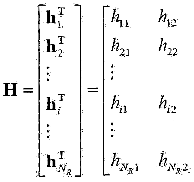


Claims
Priority Applications (2)
| Application Number | Priority Date | Filing Date | Title |
|---|---|---|---|
| KR1020137028923A KR20140031251A (ko) | 2011-06-15 | 2012-06-15 | 무선 접속 시스템에서 무선 자원 할당 방법 및 이를 위한 장치 |
| US14/115,555 US9237455B2 (en) | 2011-06-15 | 2012-06-15 | Method for allocating wireless resources in a wireless access system, and apparatus therefor |
Applications Claiming Priority (2)
| Application Number | Priority Date | Filing Date | Title |
|---|---|---|---|
| US201161497064P | 2011-06-15 | 2011-06-15 | |
| US61/497,064 | 2011-06-15 |
Publications (2)
| Publication Number | Publication Date |
|---|---|
| WO2012173434A2 true WO2012173434A2 (ko) | 2012-12-20 |
| WO2012173434A3 WO2012173434A3 (ko) | 2013-04-04 |
Family
ID=47357629
Family Applications (1)
| Application Number | Title | Priority Date | Filing Date |
|---|---|---|---|
| PCT/KR2012/004756 Ceased WO2012173434A2 (ko) | 2011-06-15 | 2012-06-15 | 무선 접속 시스템에서 무선 자원 할당 방법 및 이를 위한 장치 |
Country Status (3)
| Country | Link |
|---|---|
| US (1) | US9237455B2 (ko) |
| KR (1) | KR20140031251A (ko) |
| WO (1) | WO2012173434A2 (ko) |
Cited By (4)
| Publication number | Priority date | Publication date | Assignee | Title |
|---|---|---|---|---|
| CN104540230A (zh) * | 2015-01-30 | 2015-04-22 | 深圳酷派技术有限公司 | 一种上行调度方法及装置 |
| KR20150089547A (ko) * | 2014-01-28 | 2015-08-05 | 삼성전자주식회사 | 방송 수신 장치, 외부 장치, 신호 생성 방법 및 신호 수신 방법 |
| WO2015130559A1 (en) * | 2014-02-25 | 2015-09-03 | Microsoft Technology Licensing, Llc | Guard band usage for wireless data transmission |
| CN114765901A (zh) * | 2021-12-20 | 2022-07-19 | 成都极米科技股份有限公司 | 多链路设备连接管理方法、装置、设备及存储介质 |
Families Citing this family (27)
| Publication number | Priority date | Publication date | Assignee | Title |
|---|---|---|---|---|
| US9706498B2 (en) * | 2011-06-20 | 2017-07-11 | Lg Electronics Inc. | Method for controlling transmission power in a wireless access system and apparatus for same |
| US9137804B2 (en) * | 2011-06-21 | 2015-09-15 | Mediatek Inc. | Systems and methods for different TDD configurations in carrier aggregation |
| WO2014017716A1 (ko) * | 2012-07-23 | 2014-01-30 | 엘지전자 주식회사 | 무선 통신 시스템에서 하향링크 제어 채널을 위한 분산적 자원 할당에 따른 다이버시티 이득 획득 방법 및 이를 위한 장치 |
| US10334588B2 (en) | 2013-12-11 | 2019-06-25 | Qualcomm Incorporated | Carrier sense adaptive transmission (CSAT) coordination in unlicensed spectrum |
| US10499421B2 (en) * | 2014-03-21 | 2019-12-03 | Qualcomm Incorporated | Techniques for configuring preamble and overhead signals for transmissions in an unlicensed radio frequency spectrum band |
| CN106165325B (zh) * | 2014-04-24 | 2019-01-08 | 松下电器(美国)知识产权公司 | 发送装置 |
| KR102143505B1 (ko) * | 2014-04-24 | 2020-08-11 | 한국전자통신연구원 | 주파수 공유대역에서 가용채널 확보를 위해 우선 채널을 할당하는 네트워크 관리 장치 및 그 방법 |
| CN105309000A (zh) * | 2014-04-25 | 2016-02-03 | 华为技术有限公司 | 一种基站、用户设备、资源获取方法和系统 |
| WO2015174438A1 (ja) * | 2014-05-15 | 2015-11-19 | 株式会社Nttドコモ | ユーザ端末、無線基地局、無線通信方法及び無線通信システム |
| US9513671B2 (en) | 2014-08-01 | 2016-12-06 | Microsoft Technology Licensing, Llc | Peripheral retention device |
| US10191986B2 (en) | 2014-08-11 | 2019-01-29 | Microsoft Technology Licensing, Llc | Web resource compatibility with web applications |
| US9705637B2 (en) | 2014-08-19 | 2017-07-11 | Microsoft Technology Licensing, Llc | Guard band utilization for wireless data communication |
| US9397723B2 (en) | 2014-08-26 | 2016-07-19 | Microsoft Technology Licensing, Llc | Spread spectrum wireless over non-contiguous channels |
| US9424048B2 (en) | 2014-09-15 | 2016-08-23 | Microsoft Technology Licensing, Llc | Inductive peripheral retention device |
| US10278089B2 (en) | 2014-09-30 | 2019-04-30 | Telefonaktiebolaget Lm Ericsson (Publ) | Determining a centre frequency in an unlicensed frequency band to use |
| US10980045B2 (en) * | 2014-10-02 | 2021-04-13 | Qualcomm Incorporated | Techniques for managing power on an uplink component carrier transmitted over a shared radio frequency spectrum band |
| KR101931949B1 (ko) * | 2014-12-04 | 2019-03-20 | 엘지전자 주식회사 | 무선랜 시스템에서 fdr 전송 기법 및 이를 위한 장치 |
| CN106535254B (zh) * | 2015-09-09 | 2022-01-14 | 华为技术有限公司 | 一种确定多点传输资源的方法及装置 |
| CN107277817A (zh) * | 2016-04-08 | 2017-10-20 | 中兴通讯股份有限公司 | 一种保护频带使用方法及无线电装置 |
| WO2018217073A1 (ko) * | 2017-05-26 | 2018-11-29 | 엘지전자 주식회사 | 무선 통신 시스템에서 단말이 전송 블록에 대한 전송 자원을 선택하는 방법 및 이를 위한 장치 |
| US10411764B2 (en) * | 2017-10-31 | 2019-09-10 | Industry-Academic Cooperation Foundation, Yonsei University | Apparatus and method for transmitting and receiving information and power in wireless communication system |
| US10701694B2 (en) * | 2018-08-21 | 2020-06-30 | Phazr, Inc. | Selective crest factor reduction and digital pre-distortion of physical channels and physical signals |
| KR102813634B1 (ko) * | 2019-09-19 | 2025-05-29 | 삼성전자주식회사 | 무선 통신 시스템에서 가드밴드를 할당하기 위한 장치 및 방법 |
| US20230056592A1 (en) * | 2020-03-05 | 2023-02-23 | Google Llc | User Equipment-Autonomously Triggered-Sounding Reference Signals |
| CN116783981A (zh) * | 2021-02-23 | 2023-09-19 | 华为技术有限公司 | 用于多链路设备的链路操作的方法和装置 |
| US12598505B2 (en) * | 2021-03-05 | 2026-04-07 | Telefonaktiebolaget Lm Ericsson (Publ) | Interference detection mechanisms for microwave radio link transceivers |
| KR102835267B1 (ko) * | 2024-10-22 | 2025-07-17 | (주)에이알테크놀로지 | 간섭분석 기법을 이용한 무선 통신망의 채널 할당 방법 |
Family Cites Families (6)
| Publication number | Priority date | Publication date | Assignee | Title |
|---|---|---|---|---|
| KR101145847B1 (ko) | 2006-07-14 | 2012-05-17 | 삼성전자주식회사 | 무선 인식 환경에서 숨겨진 인컴번트 시스템을 탐지하기위한 시그널링 방법 및 상기 방법에 채용되는 채널 분할방법 |
| WO2010027308A1 (en) | 2008-09-05 | 2010-03-11 | Telefonaktiebolaget L M Ericsson (Publ) | Coordinated transmission for secondary usage |
| KR101443213B1 (ko) | 2008-10-10 | 2014-09-24 | 삼성전자주식회사 | 동적으로 할당되는 공용제어채널 정보를 이용한 인지 무선 통신 방법 |
| US8532041B1 (en) * | 2009-04-24 | 2013-09-10 | Marvell International Ltd. | Method for transmitting information in a regulated spectrum and network configured to operate in the regulated spectrum |
| US8364188B2 (en) * | 2010-06-04 | 2013-01-29 | Alcatel Lucent | Method and controller for allocating whitespace spectrum |
| US8451789B2 (en) * | 2010-06-15 | 2013-05-28 | Nokia Corporation | Method to request resources in TV white spaces type environment |
-
2012
- 2012-06-15 WO PCT/KR2012/004756 patent/WO2012173434A2/ko not_active Ceased
- 2012-06-15 KR KR1020137028923A patent/KR20140031251A/ko not_active Withdrawn
- 2012-06-15 US US14/115,555 patent/US9237455B2/en not_active Expired - Fee Related
Cited By (15)
| Publication number | Priority date | Publication date | Assignee | Title |
|---|---|---|---|---|
| EP3036895A4 (en) * | 2014-01-28 | 2017-05-03 | Samsung Electronics Co., Ltd. | Broadcasting receiving apparatus, external apparatus, method for generating signal, and method for receiving signal |
| KR20150089547A (ko) * | 2014-01-28 | 2015-08-05 | 삼성전자주식회사 | 방송 수신 장치, 외부 장치, 신호 생성 방법 및 신호 수신 방법 |
| WO2015115727A1 (en) | 2014-01-28 | 2015-08-06 | Samsung Electronics Co., Ltd. | Broadcasting receiving apparatus, external apparatus, method for generating signal, and method for receiving signal |
| KR102130683B1 (ko) * | 2014-01-28 | 2020-07-06 | 삼성전자주식회사 | 방송 수신 장치, 외부 장치, 신호 생성 방법 및 신호 수신 방법 |
| CN105794249B (zh) * | 2014-01-28 | 2019-11-26 | 三星电子株式会社 | 广播接收装置、用于生成信号的方法以及用于接收信号的方法 |
| CN105794249A (zh) * | 2014-01-28 | 2016-07-20 | 三星电子株式会社 | 广播接收装置、外部装置、用于生成信号的方法以及用于接收信号的方法 |
| US9699662B2 (en) | 2014-01-28 | 2017-07-04 | Samsung Electronics Co., Ltd. | Broadcasting receiving apparatus, external apparatus, method for generating signal, and method for receiving signal |
| US9883406B2 (en) | 2014-02-25 | 2018-01-30 | Microsoft Technology Licensing, Llc | Guard band usage for wireless data transmission |
| US9357402B2 (en) | 2014-02-25 | 2016-05-31 | Microsoft Technology Licensing, Llc | Guard band usage for wireless data transmission |
| WO2015130559A1 (en) * | 2014-02-25 | 2015-09-03 | Microsoft Technology Licensing, Llc | Guard band usage for wireless data transmission |
| WO2016119354A1 (zh) * | 2015-01-30 | 2016-08-04 | 宇龙计算机通信科技(深圳)有限公司 | 一种上行调度方法及装置 |
| CN104540230A (zh) * | 2015-01-30 | 2015-04-22 | 深圳酷派技术有限公司 | 一种上行调度方法及装置 |
| CN104540230B (zh) * | 2015-01-30 | 2018-11-06 | 深圳酷派技术有限公司 | 一种上行调度方法及装置 |
| CN114765901A (zh) * | 2021-12-20 | 2022-07-19 | 成都极米科技股份有限公司 | 多链路设备连接管理方法、装置、设备及存储介质 |
| CN114765901B (zh) * | 2021-12-20 | 2023-05-02 | 极米科技股份有限公司 | 多链路设备连接管理方法、装置、设备及存储介质 |
Also Published As
| Publication number | Publication date |
|---|---|
| WO2012173434A3 (ko) | 2013-04-04 |
| US20140080501A1 (en) | 2014-03-20 |
| US9237455B2 (en) | 2016-01-12 |
| KR20140031251A (ko) | 2014-03-12 |
Similar Documents
| Publication | Publication Date | Title |
|---|---|---|
| KR101947555B1 (ko) | 무선 접속 시스템에서 신호 전송 방법 및 이를 위한 장치 | |
| US9237455B2 (en) | Method for allocating wireless resources in a wireless access system, and apparatus therefor | |
| US9706498B2 (en) | Method for controlling transmission power in a wireless access system and apparatus for same | |
| US10306619B2 (en) | Method and apparatus for channel estimation for radio link between a base station and a relay station | |
| US10070414B2 (en) | Method for reporting a channel quality indicator by a relay node in a wireless communication system, and apparatus for same | |
| KR101901955B1 (ko) | 하향링크 채널 수신 방법 및 사용자기기와, 하향링크 채널 전송 방법 및 기지국 | |
| US9648632B2 (en) | Communication method considering carrier type and apparatus for same | |
| US11336413B2 (en) | Method for transmitting/receiving reference signal in wireless communication system, and device therefor | |
| US10200176B2 (en) | Method and apparatus for reducing inter-cell interference in radio communication system | |
| US8737307B2 (en) | Apparatus for performing comp communication using a precoded sounding reference signal and method of the same | |
| US9876625B2 (en) | Inter-cell interference coordination in a wireless communication system | |
| US9504027B2 (en) | Method and apparatus for transmitting a control channel and a data channel in a wireless communication system | |
| KR102024609B1 (ko) | 매시브 mimo를 지원하는 무선 통신 시스템에서 참조 신호의 생성 방법 | |
| KR101837496B1 (ko) | 마이크로 기지국, 유저단말 및 무선통신방법 | |
| WO2015122629A1 (ko) | 무선 통신 시스템에서 신호를 송수신하기 위한 방법 및 이를 위한 장치 | |
| WO2012138097A2 (ko) | 무선 통신 시스템에서 하향링크 제어 채널을 송수신하는 방법 및 장치 | |
| WO2013183956A1 (ko) | 무선 통신 시스템에서 epdcch를 통한 제어정보 수신 방법 및 장치 | |
| KR20130137643A (ko) | 무선 통신 시스템에서 단말 간의 통신 방법 및 장치 |
Legal Events
| Date | Code | Title | Description |
|---|---|---|---|
| 121 | Ep: the epo has been informed by wipo that ep was designated in this application |
Ref document number: 12800181 Country of ref document: EP Kind code of ref document: A2 |
|
| ENP | Entry into the national phase |
Ref document number: 20137028923 Country of ref document: KR Kind code of ref document: A |
|
| WWE | Wipo information: entry into national phase |
Ref document number: 14115555 Country of ref document: US |
|
| NENP | Non-entry into the national phase |
Ref country code: DE |
|
| 122 | Ep: pct application non-entry in european phase |
Ref document number: 12800181 Country of ref document: EP Kind code of ref document: A2 |