WO2012176254A1 - 閉サイクルガスタービン - Google Patents
閉サイクルガスタービン Download PDFInfo
- Publication number
- WO2012176254A1 WO2012176254A1 PCT/JP2011/064021 JP2011064021W WO2012176254A1 WO 2012176254 A1 WO2012176254 A1 WO 2012176254A1 JP 2011064021 W JP2011064021 W JP 2011064021W WO 2012176254 A1 WO2012176254 A1 WO 2012176254A1
- Authority
- WO
- WIPO (PCT)
- Prior art keywords
- turbine
- compressor
- cycle gas
- gas turbine
- clutch
- Prior art date
- Legal status (The legal status is an assumption and is not a legal conclusion. Google has not performed a legal analysis and makes no representation as to the accuracy of the status listed.)
- Ceased
Links
Images


Classifications
-
- F—MECHANICAL ENGINEERING; LIGHTING; HEATING; WEAPONS; BLASTING
- F02—COMBUSTION ENGINES; HOT-GAS OR COMBUSTION-PRODUCT ENGINE PLANTS
- F02C—GAS-TURBINE PLANTS; AIR INTAKES FOR JET-PROPULSION PLANTS; CONTROLLING FUEL SUPPLY IN AIR-BREATHING JET-PROPULSION PLANTS
- F02C1/00—Gas-turbine plants characterised by the use of hot gases or unheated pressurised gases, as the working fluid
- F02C1/04—Gas-turbine plants characterised by the use of hot gases or unheated pressurised gases, as the working fluid the working fluid being heated indirectly
- F02C1/10—Closed cycles
-
- F—MECHANICAL ENGINEERING; LIGHTING; HEATING; WEAPONS; BLASTING
- F01—MACHINES OR ENGINES IN GENERAL; ENGINE PLANTS IN GENERAL; STEAM ENGINES
- F01D—NON-POSITIVE DISPLACEMENT MACHINES OR ENGINES, e.g. STEAM TURBINES
- F01D19/00—Starting of machines or engines; Regulating, controlling, or safety means in connection therewith
-
- F—MECHANICAL ENGINEERING; LIGHTING; HEATING; WEAPONS; BLASTING
- F05—INDEXING SCHEMES RELATING TO ENGINES OR PUMPS IN VARIOUS SUBCLASSES OF CLASSES F01-F04
- F05D—INDEXING SCHEME FOR ASPECTS RELATING TO NON-POSITIVE-DISPLACEMENT MACHINES OR ENGINES, GAS-TURBINES OR JET-PROPULSION PLANTS
- F05D2260/00—Function
- F05D2260/85—Starting
Definitions
- the present invention relates to a closed cycle gas turbine that facilitates starting.
- gas turbines that are widely used generally drive a compressor at about 55% of the turbine output, and the remaining 45% is used as power. For this reason, in order to improve the efficiency of the gas turbine, it is necessary to reduce the compressor driving power as much as possible.
- Patent Document 1 As a means for reducing compressor drive power, compression efficiency is generally improved. However, a significant improvement that can reduce the compression power by half cannot be expected only by improving the efficiency of the compressor. On the other hand, as disclosed in Patent Document 1 and Non-Patent Document 1, if a closed cycle gas turbine using CO 2 as the working fluid is operated at supercritical pressure, the power for driving the compressor is 20 It is known that it can be reduced to about%.
- Non-Patent Document 2 when a radial flow turbine is used as the turbine, the problem described in Non-Patent Document 2 occurs. That is, the radial flow turbine and the centrifugal compressor are structurally identical except that the flow direction of the working fluid and the rotation direction of the impeller are opposite to each other. When driven by a motor, centrifugal force acts on the working fluid in the impeller in the direction from the turbine outlet toward the inlet. In order to generate a flow from the turbine inlet to the outlet at the time of starting, it is necessary to apply a pressure difference between the inlet and the outlet to overcome this centrifugal force.
- the compressor inlet state is set near a high density pseudo-critical point, and the turbine inlet is operated in a state close to perfect gas to reduce the compression power. Therefore, when the compressor and the turbine are designed under these conditions, the outer diameter of the turbine impeller is approximately twice the outer diameter of the compressor impeller.
- the inlet / outlet pressure difference of the centrifugal compressor is proportional to the square of the outer diameter of the impeller if the rotational speed is the same, if the outer diameter of the turbine impeller is too larger than the outer diameter of the compressor impeller, the compressor is started at the start.
- the centrifugal force generated in the turbine impeller is superior to the pressure difference between the turbine inlet and outlet generated in the above, causing a problem that the gas turbine cannot be started due to a backflow from the turbine inlet toward the compressor outlet.
- the compressor outlet pressure is higher than the surge pressure, which may cause surging in the compressor and cause abnormal vibration of the pipeline and damage of the impeller and bearings.
- the outer diameter of the turbine impeller in order to avoid the surging of the compressor and start the turbine, must be 1.3 times or less than the outer diameter of the compressor impeller. Yes.
- the turbine when the turbine is an axial flow type, there is no reverse flow at the time of starting unlike a radial flow turbine, but there is a great difference in the mass flow rate between the compressor and the turbine. That is, as described above, at the design point of the closed cycle gas turbine using CO 2 as the working fluid, the density of the working fluid at the compressor inlet is more than four times the density at the turbine inlet. To equalize the mass flow rate of the compressor, the compressor air flow must be less than 1/4 of the turbine air flow. Since the density of the working fluid at the compressor and the turbine inlet is equal at the time of start-up, when driven by a motor, the mass flow rate of the compressor becomes 1/4 or less of the turbine, and the closed cycle cannot be increased and the operating condition cannot be reached.
- Patent Document 2 discloses a technique in which a bypass valve for bypassing a turbine is provided and the bypass valve is fully closed at the start, and then the opening degree of the bypass valve is adjusted to control the gas turbine safely.
- the turbine is installed in the main flow and the working fluid can always pass through. Therefore, when a radial flow turbine is used, the reverse flow at the start cannot be prevented.
- the turbine flow rate becomes excessive and the cycle cannot be increased.
- Patent Document 3 in a system for driving a turbine with exhaust gas of an internal combustion engine, a valve for shutting off the exhaust gas to the turbine and a valve for bypassing the turbine are provided, and the exhaust gas is selectively circulated to the turbine or released to the atmosphere. Techniques for making them disclosed are disclosed.
- the internal combustion engine is a turbine-driven power source, and the optional turbine can be started if the internal combustion engine is in operation. For this reason, this technology cannot cope with the start-up problem peculiar to the closed cycle gas turbine.
- the present invention is a problem at the start of a closed cycle gas turbine, i.e. (1) When a radial flow turbine is used, a reverse flow is generated in the turbine at the start and surging occurs in the compressor. (2) When an axial flow turbine is used, the turbine flow rate becomes excessive at the start and the cycle cannot be increased.
- An object of the present invention is to provide a closed-cycle gas turbine that solves the above-described problems that cause stall in turbine blades and that can be stably started.
- the compressor and the turbine are connected by a flow path, and a regenerator, a heater, and a cooler are provided along the flow path, and are connected to the compressor and the turbine.
- a closed-cycle gas turbine having a starter motor has an expansion / decompression unit that replaces the turbine, and a turbine operation control unit that controls the operation of the turbine until a turbine start condition is reached when the closed-cycle gas turbine is started.
- the expansion / decompression unit is a bypass that includes an expansion valve and is connected to the flow path of the turbine outlet via a bypass merging unit, and the turbine operation control unit includes: It is a flow control valve installed between the outlet of the turbine and the bypass junction.
- the expansion / decompression section is a bypass provided with an expansion valve and connected to the flow path of the turbine outlet via a bypass merging section
- the turbine operation control section includes: It is a check valve installed between the outlet of the turbine and the bypass junction.
- the expansion / decompression section and the turbine operation control section are flow control valves installed in the flow path.
- the compressor and the turbine are connected by a shaft having a clutch.
- the turbine operation control unit includes the clutch and the flow control valve.
- the compressor and the turbine are connected by a shaft having a clutch.
- the turbine operation control unit includes the clutch and the check valve.
- the compressor and the turbine are connected by a shaft having a clutch.
- the expansion / decompression unit is a flow control valve installed in the flow path.
- the turbine operation control unit is the clutch.
- the compressor and the turbine are connected by a shaft having a clutch.
- the turbine operation control unit includes the clutch.
- the flow path in the turbine whose operation is controlled by the clutch constitutes the expansion / decompression unit.
- the clutch may be an automatic engagement / disengagement clutch configured to transmit power only from the turbine to the compressor side.
- the closed cycle gas turbine further includes a compressor turbine connected to the compressor, and the compressor turbine includes the expansion / decompression unit and the turbine operation control unit. Constitute.
- the operation of the turbine is controlled by the turbine operation control unit, and the operation condition of the closed cycle can be reached by the expansion / decompression unit as an alternative to the turbine. Therefore, the closed cycle gas turbine can be started stably.
- the object of stably starting a closed cycle gas turbine is achieved by using an expansion / decompression unit that replaces the turbine at the time of startup and a turbine operation control unit that controls the operation of the turbine. can do.
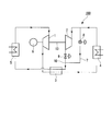
- FIG. 1 shows a closed cycle gas turbine (hereinafter referred to as “cycle”) 100 according to a first embodiment of the present invention.
- the cycle 100 includes a compressor 1, a turbine 2, a regenerator 3, a heater 4, a cooler 5, a motor / generator 6 as a starting motor, a bypass 7, an expansion valve 8, and a flow rate control. And a valve 9.
- a conventional turbine can be used as the turbine 2 and the type thereof is not limited. That is, as the turbine 2, a turbine of either a radial flow turbine or an axial flow turbine can be used.
- the compressor 1 and the turbine 2 are connected to a motor / generator 6 through a shaft 13 so that power can be transmitted.
- the outlet of the compressor 1 and the inlet of the turbine 2 are connected by piping through a regenerator 3 and a heater 4. That is, the regenerator 3 and the heater 4 are provided along a flow path connecting the outlet of the compressor 1 and the inlet of the turbine 2.
- the turbine 2 is provided with a bypass 7 having an expansion valve 8.
- the bypass 7 branches off from the pipe before the inlet of the turbine 2 and is connected to the outlet pipe of the turbine 2.
- the joining portion of the bypass 7 and the piping at the outlet of the turbine 2 becomes the bypass joining portion 10.
- a flow control valve 9 is installed between the outlet of the turbine 2 and the bypass junction 10.
- the bypass junction 10 and the inlet of the compressor 1 are connected by piping through the regenerator 3 and the cooler 5, and the cycle 100 constitutes a closed cycle. That is, the regenerator 3 and the cooler 5 are provided along a pipe (flow path) that connects the bypass junction 10 and the inlet of the compressor 1.
- the cycle 100 uses CO 2 as a working fluid.
- the cycle 100 is filled with a predetermined amount of CO 2 after evacuation.
- the cooler 5 is cooled by a cooling heat medium having an outside air temperature.
- the expansion valve 8 is opened at a predetermined opening, and the flow control valve 9 is closed.
- the motor / generator 6 is used as a starting motor to drive the compressor 1 and the turbine 2.
- the heating speed of the compressor 1 and the turbine 2 is increased while heating the CO 2 with the heater 4.
- the operating condition of the cycle 100 according to the present embodiment can be evaluated by Expression (1).
- p pressure (Pa)
- ⁇ density (kg / m 3 )
- U is the peripheral speed (m / s) of the impeller in the case of a radial turbine
- the average axial flow velocity in the case of an axial turbine) m / s.
- Subscripts i and o represent an inlet and an outlet, respectively.
- FIG. 2 shows the state from the start of the cycle 100 to the rated operation according to the present embodiment on a Mollier diagram in which the vertical axis pressure (MPa) and the horizontal axis specific enthalpy (kJ / kg) are expressed.
- MPa vertical axis pressure
- kJ / kg horizontal axis specific enthalpy
- a broken line extending upward from the critical point is a quasi-critical line connecting points at which the specific heat steeply increases with respect to temperature change at each pressure.
- the left side of the isothermal line at the critical temperature of 31.06 ° C. is the liquid phase and the right side is the gas phase, but the density changes greatly in the vicinity of the pseudocritical line.
- the cycle points indicated by white circles ( ⁇ ) in the figure indicate the operation results of the cycle 100 according to the present embodiment.
- a black circle ( ⁇ ) (4.8 MPa, 25.3 ° C.) described as “before starting” is a state in which a predetermined amount of CO 2 is sealed in the cycle and then equilibrium is reached at the ambient temperature.
- the CO 2 temperature in each component is equal.
- the pressure of CO 2 in the constituent devices are equal.
- the density of CO 2 at the compressor inlet and the turbine inlet is both equal to 122.8 kg / m 3 .
- the cycle is started by the above-described procedure, and the state after time t1 is a rectangle connecting the white circle ( ⁇ ) indicated by t1 with a straight line, and the left oblique line indicates the change in CO 2 in the compressor 1 on the right side.
- the vertical line indicates the change in CO 2 in the expansion valve 8.
- the operation of the turbine 2 is controlled by the flow rate control valve 9 that is the turbine operation control unit, and the cycle 100 is controlled by the bypass 7 that is the expansion / decompression unit.
- the operating conditions can be reached.
- the turbine 2 can be operated to perform a self-supporting operation. Therefore, the cycle 100 can be started stably regardless of the type of the turbine 2. That is, even if the turbine 2 is a radial flow turbine or an axial flow turbine, the cycle 100 can be stably started.
- the flow control valve 9 may be opened to such an extent that the start of the cycle 100 is not affected.
- FIG. 3 shows a cycle 200 according to the second embodiment of the present invention.
- the cycle 200 is different from the cycle 100 according to the first embodiment in that the check valve 11 is used as a turbine operation control unit instead of the flow rate control valve 9 in the cycle 100.
- FIG. 4 shows a cycle 300 according to the third embodiment of the present invention.
- the cycle 300 is different from the first embodiment and the second embodiment in that the cycle 300 does not include the bypass 7, the expansion valve 8, and the check valve 11.
- the flow control valve 9 installed in the pipe before the inlet of the turbine 2 constitutes an expansion / decompression unit and a turbine operation control unit.
- the opening degree of the flow control valve 9 the flow rate of the working medium (CO 2 ) flowing into the turbine 2 is controlled, and the operation of the turbine 2 is controlled. Further, by controlling the operation of the turbine 2, the flow path in the turbine 2 becomes an expansion / decompression unit, and the cycle 300 can be stably pressurized.
- FIG. 5 shows a cycle 400 according to the fourth embodiment of the present invention.
- the cycle 400 is different from the first embodiment in that a clutch 12 is provided as a turbine operation control unit on a shaft 43 that connects the compressor 1 and the turbine 2 so that power can be transmitted.
- the clutch 12 is disengaged. Then, the clutch 12 is engaged when the expansion valve 8 is closed and the flow rate control valve 9 is opened. With this configuration, the turbine 2 does not rotate until the operating conditions of the cycle 400 are reached.
- the cycle 400 also includes a bypass 7 with an expansion valve 8. For this reason, in the cycle 400, the operation of the turbine 2 is also controlled by the bypass 7 as in the first embodiment. That is, in the present embodiment, the bypass 7 including the expansion valve 8 and the clutch 12 constitute a turbine operation control unit.
- the clutch 12 shown in FIG. 6 is a one-way clutch, and includes a shaft 43 and an outer ring 14 that is provided concentrically therewith and periodically has a plurality of axial grooves whose depth continuously changes in one circumferential direction. Composed. A roller 15 is attached to the outer ring 14 by a spring 16 in a groove between the outer ring 14 and the shaft 43.
- FIG. 7 shows a cycle 500 according to the fifth embodiment of the present invention.
- the cycle 500 has the same basic configuration as the cycle 200 according to the second embodiment of the present invention, except that the clutch 12 is provided on the shaft 43 that connects the compressor 1 and the turbine 2 so that power can be transmitted. Different from 200.
- the clutch 12 is disengaged. Then, the expansion valve 8 is closed, the check valve is operated with a sufficient inlet / outlet differential pressure to drive the turbine 2, and the clutch 12 is engaged when the working fluid flows into the turbine 2. With this configuration, the turbine 2 does not rotate until the operating conditions of the cycle 500 are reached.
- the cycle 500 also includes a bypass 7 with an expansion valve 8. For this reason, in the cycle 500, the operation of the turbine 2 is also controlled by the bypass 7 as in the second embodiment. That is, in the present embodiment, the bypass 7 including the expansion valve 8 and the clutch 12 constitute a turbine operation control unit.
- the turbine 2 does not rotate until the start condition is reached. For this reason, even if the check valve 11 is cut off at the start of the cycle, an effect of preventing overheating of the turbine 2 due to internal circulation of the working fluid in the turbine 2 can be obtained.
- FIG. 8 shows a cycle 600 according to the sixth embodiment of the present invention.
- the cycle 600 is different from the cycle 400 according to the fourth embodiment of the present invention in that the cycle 600 does not include the bypass 7 and the expansion valve 8.
- the flow rate control valve 9 is used as expansion means when the cycle 600 is started. For this reason, there is an advantage that the cycle configuration and control can be simplified compared to the cycle 400. Further, compared to the cycle 100 according to the first embodiment, since only the flow control valve 9 and the clutch 12 need be controlled at the time of starting, the control is facilitated and the turbine 2 is not overheated even in the shut-off operation. can get.
- FIG. 9 shows a cycle 700 according to the seventh embodiment of the present invention.
- the cycle 700 is different from the third embodiment, the fourth embodiment, and the fifth embodiment in that it does not have the bypass 7, the expansion valve 8, the flow control valve 9, or the check valve 11.
- the cycle 700 uses the flow path of the turbine 2 that does not rotate at the start as an expansion means. That is, the operation is controlled by the clutch 12, and the flow path in the turbine 2 that does not rotate constitutes an expansion / decompression unit.
- the cycle 700 Since the flow path in the turbine 2 that does not rotate has a smaller flow path resistance than when the expansion valve 8 or the flow rate control valve 9 is used, the cycle is not boosted unless the rotation speed is higher than in other embodiments. .
- the cycle 700 has an advantage that the cycle configuration can be simplified.
- the eighth embodiment of the present invention will be described below with reference to FIG.
- symbol is attached
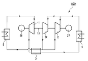
- the eighth embodiment shown in FIG. 10 is different from the other embodiments in that a compressor turbine connected to the compressor is provided in addition to the power generation turbine.
- a cycle 800 shown in FIG. 8 includes a compressor turbine 22 in addition to the turbine 2.
- the compressor turbine 22 is connected together with the compressor 1 by a shaft 13 to a motor 26 which is a starter motor so as to be able to transmit power.
- the turbine 2 connected to the shaft 13 in the first embodiment or the like is not connected to the shaft 13 in the present embodiment.
- the turbine 2 is connected in parallel with the compressor turbine 22.
- a motor / generator 27 is connected to the turbine 2 so that power can be transmitted.
- the compressor turbine 22 may be of any type, but a turbine having a smaller capacity than the turbine 2 is used.
- the outer diameter of the impeller is designed to be approximately 1.3 times or less than the impeller of the compressor 1, and when the compressor turbine 22 is an axial flow turbine, the air volume is the turbine 2. It is designed to be about 1/3 of that.
- the compressor turbine 22 constitutes an expansion / decompression unit and a turbine operation control unit. That is, at the start of the cycle 800, the turbine 2 is not operated, and only the compressor turbine 22 is operated and operated. Then, the cycle is increased by the compressor turbine 22, and when the value obtained by the equation (1) becomes equal to or higher than a predetermined value determined from the characteristics of the turbine 2, the motor / generator 27 starts the turbine 2 to start the heater 4. Is increased, the turbine 2 enters a self-sustaining state, and the motor / generator 27 operates as a generator to obtain an electrical output.
- the compressor turbine 22 also drives the compressor 1 at this time, the power supplied to the motor 26 can be reduced, and the power generation efficiency of the cycle can be increased.
- the heat source of the heater 4 is exhaust heat of a gas turbine, a gas engine, and various heat systems, when the amount of exhaust heat increases, the output of the compressor turbine 22 can be increased and the power supplied to the motor 26 can be greatly reduced. There is also an effect.
- the clutch 12 is the automatic fitting / removing clutch 12 shown in FIG. Since the turbine output can be automatically transmitted to the compressor 1 without operation, cycle start control is facilitated.
- the closed cycle gas turbine can be stably started without damaging the compressor and the turbine. For this reason, it can be applied to a closed cycle gas turbine using various fuels, solar heat, biomass, industrial exhaust heat, and the like.
Landscapes
- Engineering & Computer Science (AREA)
- Chemical & Material Sciences (AREA)
- Combustion & Propulsion (AREA)
- Mechanical Engineering (AREA)
- General Engineering & Computer Science (AREA)
- Control Of Turbines (AREA)
Abstract
この閉サイクルガスタービンは、圧縮機とタービンが流路で接続され、前記流路に沿って再生器、加熱器、冷却器が備えられ、前記圧縮機及び前記タービンに接続された始動用モータとを有する閉サイクルガスタービンであって、前記タービンの代替となる膨脹・減圧部と、閉サイクルガスタービンの始動時にはタービン起動条件に達するまでタービンの作動を制御するタービン作動制御部とを有する。
Description
本発明は、始動を容易とする閉サイクルガスタービンに関するものである。
現在、広く使用されているガスタービンは一般にタービン出力の約55%で圧縮機を駆動し、残りの45%が動力として利用されている。このため、ガスタービンの効率を向上させるには極力圧縮機駆動動力を低減する必要がある。
圧縮機駆動動力を低減する手段として、一般に圧縮効率の向上が図られている。しかしながら、圧縮機の効率向上だけでは圧縮動力を半減できるような大幅な改善は期待できない。これに対し、特許文献1や非特許文献1に開示されているように作動流体をCO2とした閉サイクルガスタービンを超臨界圧力で運転すれば、圧縮機を駆動する動力をタービン出力の20%程度に低減できることが知られている。
しかし、これは設計点の状態で運転できたときの評価であり、ガスタービンを始動してこの設計点の状態まで立ち上げる方法についてはこれらの文献では考慮されていない。即ち、閉サイクルガスタービンにCO2を封入した始動前の状態は、各構成機器における作動流体の温度や圧力は等しく、また超臨界圧力ではない。そこでこの状態から設計点の状態まで立ち上げるには圧縮機をモータで駆動して作動流体を昇圧、循環させ加熱器で加熱してタービンを自立させる始動運転を行わなければならない。
ここでタービンとして半径流タービンを使用する場合、非特許文献2に記載されている問題が生じる。即ち、半径流タービンと遠心圧縮機は、作動流体の流れ方向と羽根車の回転方向が逆向きである点を除けば構造的には全く同じであるので、ガスタービンの始動時に半径流タービンをモータで駆動すると羽根車内の作動流体にはタービン出口から入口へ向かう方向へ遠心力が働く。始動時にタービン入口から出口へ向かう流れを生じさせるには、この遠心力に打ち勝つ入口出口間圧力差を圧縮機で与える必要がある。
しかしCO2を作動流体とする該閉サイクルガスタービンでは、圧縮機入口状態を密度の大きい擬臨界点付近とし、タービン入口を完全ガスに近い状態で運転することにより圧縮動力の低減を図っているので、この条件で圧縮機とタービンを設計すると、タービンの羽根車外径は圧縮機羽根車外径の約2倍となる。ここで遠心圧縮機の出入口圧力差は回転速度が同じであれば羽根車外径の2乗に比例するので、タービンの羽根車外径が圧縮機羽根車の外径より大きすぎると、始動時に圧縮機で生じるタービン入口出口間圧力差よりタービン羽根車内で生じる遠心力の方が勝り、タービン入口から圧縮機出口に向かう逆流を生じてガスタービンが始動できないという問題を生じる。
またこのとき圧縮機出口圧力はサージ圧以上となるので、圧縮機にサージングを生じ管路の異常振動や羽根車、軸受等の破損を惹起する可能性がある。なお非特許文献2によれば、圧縮機のサージングを回避してタービンを始動するには、圧縮機羽根車外径に対しタービン羽根車の外径は1.3倍以下でなければならないとされている。
一方タービンが軸流型の場合には、半径流タービンのように始動時に逆流することは無いが、圧縮機とタービンの質量流量に大幅な乖離を生じる。即ち上述のように、CO2を作動流体とする閉サイクルガスタービンの設計点では、圧縮機入口における作動流体の密度はタービン入口における密度の4倍以上であるので、設計点で圧縮機とタービンの質量流量を等しくするには圧縮機の風量をタービン風量の1/4以下にしなければならない。始動時にはこの圧縮機とタービンの入口における作動流体の密度は等しいので、モータで駆動すると圧縮機の質量流量はタービンの1/4以下となり閉サイクルは昇圧できず運転条件に到達できない。
またこのとき、タービン入口における作動流体の密度は設計点における値の2倍程度であるので、風量が低下して翼の周速に対し作動流体の軸流速度が相対的に低下しタービン翼の仰角が増加して流れが剥離する。剥離が成長し旋回失速が発生するとタービン翼の振動や破損を惹起する可能性がある。
特許文献2には、タービンをバイパスするためのバイパス弁を設け始動時にバイパス弁を全閉にした後、バイパス弁の開度を調整してガスタービンを安全に制御する技術が開示されている。しかし該技術ではタービンは主流に設置され作動流体は常時通過可能となっているので、半径流タービンを使用した場合には始動時の逆流を防止できない。また、軸流タービンを使用した場合にはタービン流量が過大となりサイクルは昇圧できない。
特許文献3には内燃機関の排気ガスでタービンを駆動するシステムにおいて、タービンへの排気ガスを遮断する弁とタービンをバイパスする弁を設け、選択的に排気ガスをタービンへ循環させるか大気へ放出させる技術が開示されている。しかし、これらのシステムでは内燃機関がタービン駆動の動力源であり、内燃機関が運転されていれば随意タービンを始動できる。このため、閉サイクルガスタービン特有の始動時の問題に対しては該技術では対応できない。
Hasuike,H. ,et al., Test plant and preliminary test result of a bench scale closed cycle gas turbine with super-critical CO2 as working fluid, Proceedings of ASME Turbo Expo 2010 (2010)
中野 晋 他4:再生サイクル用半径流タービンの始動特性に関する研究:日本機械学会論文集(B編),75巻759号(2009-11)
本発明は、閉サイクルガスタービンの始動時の課題、すなわち、
(1)半径流タービンを使用した場合に始動時にタービンに逆流を生じ、圧縮機にサージングが発生する
(2)軸流タービンを使用した場合、始動時にタービン流量が過大となりサイクルを昇圧できない点やタービン翼に失速を生じる
上述の課題を解決し、安定して始動することが出来る閉サイクルガスタービンを提供することを目的とする。
(1)半径流タービンを使用した場合に始動時にタービンに逆流を生じ、圧縮機にサージングが発生する
(2)軸流タービンを使用した場合、始動時にタービン流量が過大となりサイクルを昇圧できない点やタービン翼に失速を生じる
上述の課題を解決し、安定して始動することが出来る閉サイクルガスタービンを提供することを目的とする。
本発明の第1の態様によれば、圧縮機とタービンが流路で接続され、前記流路に沿って再生器、加熱器、冷却器が備えられ、前記圧縮機及び前記タービンに接続された始動用モータとを有する閉サイクルガスタービンは、前記タービンの代替となる膨脹・減圧部と、閉サイクルガスタービンの始動時にはタービン起動条件に達するまでタービンの作動を制御するタービン作動制御部とを有する。
本発明の第2の態様によれば、前記膨脹・減圧部が、膨脹弁を備え、前記タービン出口の流路にバイパス合流部を介して接続されたバイパスであり、前記タービン作動制御部が、前記タービンの出口と、前記バイパス合流部との間に設置した流量制御弁である。
本発明の第3の態様によれば、前記膨脹・減圧部が、膨脹弁を備え、前記タービン出口の流路にバイパス合流部を介して接続されたバイパスであり、前記タービン作動制御部が、前記タービンの出口と、前記バイパス合流部との間に設置した逆止弁である。
本発明の第4の態様によれば、前記膨脹・減圧部および前記タービン作動制御部が、前記流路に設置した流量制御弁である。
本発明の第5の態様によれば、前記圧縮機と、前記タービンとは、クラッチを有するシャフトで接続される。前記タービン作動制御部は、前記クラッチと、前記流量制御弁とから構成される。
本発明の第6の態様によれば、前記圧縮機と、前記タービンとは、クラッチを有するシャフトで接続される。前記タービン作動制御部が、前記クラッチと、前記逆止弁とから構成される。
本発明の第7の態様によれば、前記圧縮機と、前記タービンとは、クラッチを有するシャフトで接続される。前記膨脹・減圧部は、前記流路に設置した流量制御弁である。前記タービン作動制御部は、前記クラッチである。
本発明の第8の態様によれば、前記圧縮機と、前記タービンとは、クラッチを有するシャフトで接続される。前記タービン作動制御部は、前記クラッチから構成される。前記クラッチによって作動が制御された前記タービン内の流路が前記膨張・減圧部を構成する。
前記クラッチは、前記タービンから前記圧縮機側へのみ動力を伝達できるように構成した自動嵌脱クラッチであっても良い。
本発明の第9の態様によれば、閉サイクルガスタービンは前記圧縮機に接続される圧縮機用タービンを更に備え、前記圧縮機用タービンが、前記膨脹・減圧部および前記タービン作動制御部を構成する。
本発明によれば、閉サイクルガスタービンの始動時に、タービン作動制御部によってタービンの作動を制御するとともに、タービンの代替となる膨脹・減圧部によって閉サイクルの運転条件に到達することができる。従って、安定して閉サイクルガスタービンを始動することができる。
本発明にあっては、閉サイクルガスタービンを安定して始動するという目的を、始動時にタービンの代替となる膨脹・減圧部、及びタービンの動作を制御するタービン作動制御部を使用することで達成することができる。以下、本発明の実施の形態を図に基づいて説明する。
[第1実施形態]
図1に、本発明の第1実施形態に係る閉サイクルガスタービン(以下、「サイクル」と称する)100を示す。サイクル100は、圧縮機1と、タービン2と、再生器3と、加熱器4と、冷却器5と、始動用モータであるモータ・ジェネレータ6と、バイパス7と、膨張弁8と、流量制御弁9とを備える。本実施の形態において、タービン2には従来技術のタービンを用いることができ、その形式は問わない。すなわち、タービン2としては、半径流タービン、軸流タービンいずれの形式のタービンも使用可能である。
図1に、本発明の第1実施形態に係る閉サイクルガスタービン(以下、「サイクル」と称する)100を示す。サイクル100は、圧縮機1と、タービン2と、再生器3と、加熱器4と、冷却器5と、始動用モータであるモータ・ジェネレータ6と、バイパス7と、膨張弁8と、流量制御弁9とを備える。本実施の形態において、タービン2には従来技術のタービンを用いることができ、その形式は問わない。すなわち、タービン2としては、半径流タービン、軸流タービンいずれの形式のタービンも使用可能である。
圧縮機1およびタービン2は、シャフト13によってモータ・ジェネレータ6に動力伝達可能に接続されている。圧縮機1の出口とタービン2の入口は、再生器3および加熱器4を介して配管で接続されている。すなわち、再生器3と、加熱器4は、圧縮機1の出口とタービン2の入口を接続する流路に沿って備えられている。タービン2には膨脹弁8を備えたバイパス7が設けられている。バイパス7は、タービン2の入口手前で配管から分岐し、タービン2の出口の配管に接続されている。この、バイパス7と、タービン2の出口の配管との合流部がバイパス合流部10となる。タービン2の出口とバイパス合流部10の間には流量制御弁9が設置されている。バイパス合流部10と圧縮機1の入口は再生器3および冷却器5を介して配管で接続され、サイクル100は閉サイクルを構成している。すなわち、再生器3と、冷却器5は、バイパス合流部10と圧縮機1の入口を接続する配管(流路)に沿って備えられている。
本実施形態に係るサイクル100は、作動流体としてCO2を用いる。サイクル100には、真空引きした後、CO2が所定の量封入してある。加熱器4の熱源としては、周知の各種燃料のほか、300℃以下の排熱も利用可能である。冷却器5は、外気温度程度の冷却熱媒で冷却される。
[動作]
以下、図1に基づいて、サイクル100の動作を説明する。サイクル100の始動時には、膨脹弁8を所定の開度開けておき、流量制御弁9を閉じておく。冷却器5に冷却熱媒(図示せず)を流した後、モータ・ジェネレータ6を始動用モータとして使用して圧縮機1とタービン2を駆動する。加熱器4でCO2を加熱しながら圧縮機1とタービン2の回転速度を増加させる。
以下、図1に基づいて、サイクル100の動作を説明する。サイクル100の始動時には、膨脹弁8を所定の開度開けておき、流量制御弁9を閉じておく。冷却器5に冷却熱媒(図示せず)を流した後、モータ・ジェネレータ6を始動用モータとして使用して圧縮機1とタービン2を駆動する。加熱器4でCO2を加熱しながら圧縮機1とタービン2の回転速度を増加させる。
本実施形態に係るサイクル100の運転条件は、式(1)で評価することが出来る。ここで、pは圧力(Pa)、ρは密度(kg/m3)、Uは半径流タービンの場合は羽根車の周速度(m/s)、軸流タービンの場合は平均軸流流速(m/s)である。また添字i、oはそれぞれ入口および出口を表す。
Ψ=(pi-po)/(ρiU2/2) ・・・(1)
式(1)で求める値がタービン特性から定まる所定の値以上になったらタービン2が逆流や流量過多を生じることなく出力を発生できる状態になったと判定し、膨脹弁8を閉じながら流量制御弁9を開けていく。流量制御弁9が全開となり、膨脹弁8が全閉となってタービン2に全流量流れるようになると、タービン出力が増加してやがて自立運転に入りモータ・ジェネレータ6が発電機として作動して電気出力が得られる。
[運転特性]
図2は、本実施形態に係るサイクル100の始動から定格運転までの状態を、縦軸圧力(MPa)、横軸比エンタルピー(kJ/kg)で表したモリエル線図上に示したものである。ここで、臨界点(7.38MPa、31.06℃)より左側の曲線は飽和液線、右側の曲線は飽和蒸気線であり、飽和液線より左は過冷却液、飽和蒸気線より右側は過熱蒸気、両曲線に囲まれた部分は気液二相の状態である。また、臨界点から上方に伸びる破線は各圧力で比熱が温度変化に対し急峻に最大値を示す点を連ねた擬臨界線である。臨界点より圧力が高い状態では臨界温度31.06℃の等温線の左側が液相、右側が気相であるが、密度は擬臨界線付近で大きく変化する。
図2は、本実施形態に係るサイクル100の始動から定格運転までの状態を、縦軸圧力(MPa)、横軸比エンタルピー(kJ/kg)で表したモリエル線図上に示したものである。ここで、臨界点(7.38MPa、31.06℃)より左側の曲線は飽和液線、右側の曲線は飽和蒸気線であり、飽和液線より左は過冷却液、飽和蒸気線より右側は過熱蒸気、両曲線に囲まれた部分は気液二相の状態である。また、臨界点から上方に伸びる破線は各圧力で比熱が温度変化に対し急峻に最大値を示す点を連ねた擬臨界線である。臨界点より圧力が高い状態では臨界温度31.06℃の等温線の左側が液相、右側が気相であるが、密度は擬臨界線付近で大きく変化する。
図中に白丸(○)で記したサイクル点は、本実施形態に係るサイクル100の運転結果を示す。始動前と記した黒丸(●)(4.8MPa,25.3℃)は、サイクルにCO2を所定量封入した後、雰囲気温度で平衡に達した状態である。各構成機器内のCO2の温度は等しい。また、各構成機器内のCO2の圧力も等しい。このとき、圧縮機入口とタービン入口におけるCO2の密度は共に122.8kg/m3と等しい。
この状態から上述の手順でサイクルを始動して時間t1経った状態がt1と記した白丸(○)を直線で結んだ矩形であり、左の斜線が圧縮機1におけるCO2の変化を、右側の垂線が膨脹弁8におけるCO2の変化を示している。この時点では流量制御弁9は閉じていて膨脹弁8のみ開いているので、始動時にタービン2の影響を受けることなく圧縮機1、再生器3、加熱器4、膨脹弁8および冷却器5で閉サイクルを構成し安定して運転している。
本運転では始動後時間t2経過した時点で式(1)の条件を満たしてタービン2が起動し、サイクル始動後時間t3経過した時点でタービン2が自立運転に入る。さらにサイクル始動後、時間t4経過した後にはサイクルは安定し定常運転状態にとなる。このとき圧縮機1の入口で圧力7.5MPa、温度31℃であったCO2は約11MPaまで圧縮され、再生器3でタービン2を流出した高温のCO2と熱交換した後、加熱器4で加熱され264℃の過熱ガスとなってタービン2に流入する。この高温、高圧のCO2はタービン2で7.8MPaまで膨脹する際、圧縮機1やモータ・ジェネレータ6を駆動して240℃程度まで温度が低下し、再生器3で圧縮機2から吐出されたCO2と熱交換した後、冷却器5で冷却され圧縮機1へ戻る。ここで、圧縮機1の入口におけるCO2の密度は582 kg/m3と、タービン2の入口におけるCO2の密度110kg/m3の約5.3倍となっている。
このように、本実施の形態によれば、サイクル100の始動時に、タービン作動制御部である流量制御弁9によってタービン2の作動を制御するとともに、膨脹・減圧部であるバイパス7によってサイクル100の運転条件に到達させることが出来る。サイクル100の運転条件に到達した後は、タービン2を作動させて、自立運転をすることができる。従って、タービン2の種類に関わらず、安定してサイクル100を始動することが可能となる。即ち、タービン2が半径流タービンであったとしても、軸流タービンであったとしても、安定してサイクル100を始動することが可能となる。
なお、サイクル100の始動時にタービン2の締切り運転によりタービン2の翼が過熱する場合には、サイクル100の始動に影響が無い程度に流量制御弁9を開けておいても差し支えない。
[第2実施形態]
以下、図3に基づいて、本発明の第2実施形態を説明する。なお、第1実施形態と共通する構成要件については同じ符号を付し、重複する説明は省略する。図3に、本発明の第2実施形態に係るサイクル200を示す。サイクル200は、サイクル100における流量制御弁9の代わりに、タービン作動制御部として逆止弁11を使用した点が第1実施形態に係るサイクル100と異なる。
以下、図3に基づいて、本発明の第2実施形態を説明する。なお、第1実施形態と共通する構成要件については同じ符号を付し、重複する説明は省略する。図3に、本発明の第2実施形態に係るサイクル200を示す。サイクル200は、サイクル100における流量制御弁9の代わりに、タービン作動制御部として逆止弁11を使用した点が第1実施形態に係るサイクル100と異なる。
このように構成することにより、上述の第1実施形態で得られる効果に加えて、サイクル200の始動時にタービン2が逆流することを防ぐことができるという効果が得られる。また、タービン2を駆動するに十分な出入口差圧になったときには自動的にタービン2に作動流体が流れるので、特にタービン2が半径流タービンである場合、流量制御弁9の操作が不要となり制御が簡素化される利点がある。
[第3実施形態]
以下、図4に基づいて、本発明の第3実施形態を説明する。なお、前記実施形態と共通する構成要件については同じ符号を付し、重複する説明は省略する。図4に、本発明の第3実施形態に係るサイクル300を示す。サイクル300は、バイパス7、膨脹弁8および逆止弁11を有しない点が第1実施形態および第2実施形態と異なる。本実施形態においては、タービン2の入口手前の配管に設置された流量制御弁9が、膨張・減圧部及びタービン作動制御部を構成する。すなわち、流量制御弁9の開度を調整することにより、タービン2に流入する作動媒体(CO2)の流量を制御し、タービン2の作動を制御する。また、タービン2の作動が制御されることにより、タービン2内の流路が膨張・減圧部となり、安定してサイクル300を昇圧することができる。
以下、図4に基づいて、本発明の第3実施形態を説明する。なお、前記実施形態と共通する構成要件については同じ符号を付し、重複する説明は省略する。図4に、本発明の第3実施形態に係るサイクル300を示す。サイクル300は、バイパス7、膨脹弁8および逆止弁11を有しない点が第1実施形態および第2実施形態と異なる。本実施形態においては、タービン2の入口手前の配管に設置された流量制御弁9が、膨張・減圧部及びタービン作動制御部を構成する。すなわち、流量制御弁9の開度を調整することにより、タービン2に流入する作動媒体(CO2)の流量を制御し、タービン2の作動を制御する。また、タービン2の作動が制御されることにより、タービン2内の流路が膨張・減圧部となり、安定してサイクル300を昇圧することができる。
このように構成すると、上述の効果に加えて、特にタービン2が軸流タービンの場合に、サイクル300の始動時に流量制御弁9を調整することによりタービン流量が過大となることを防止できる。これにより、安定してサイクル300を昇圧できるとともに、システム構成が簡素化できる利点を有する。
[第4実施形態]
以下、図5に基づいて、本発明の第4実施形態を説明する。なお、前記実施形態と共通する構成要件については同じ符号を付し、重複する説明は省略する。図5に、本発明の第4実施形態に係るサイクル400を示す。サイクル400は、圧縮機1とタービン2を動力伝達可能に接続するシャフト43に、タービン作動制御部としてクラッチ12を設けた点が第1実施形態と異なる。
以下、図5に基づいて、本発明の第4実施形態を説明する。なお、前記実施形態と共通する構成要件については同じ符号を付し、重複する説明は省略する。図5に、本発明の第4実施形態に係るサイクル400を示す。サイクル400は、圧縮機1とタービン2を動力伝達可能に接続するシャフト43に、タービン作動制御部としてクラッチ12を設けた点が第1実施形態と異なる。
サイクル400の始動時には、クラッチ12は切られている。そして、膨脹弁8を閉じ流量制御弁9を開けるタイミングでクラッチ12を係合させる。このように構成すると、タービン2はサイクル400の運転条件に達するまで回転しない。また、サイクル400は膨張弁8を備えたバイパス7も備えている。このため、サイクル400において、タービン2の作動は、第1実施形態と同様に、バイパス7によっても制御される。即ち、本実施形態においては、膨張弁8を備えたバイパス7と、クラッチ12とが、タービン作動制御部を構成する。
本実施形態によれば、上述の効果に加え、サイクル400の始動時に流量制御弁9を締切っても、タービン2内における作動流体の内部循環によるタービン2の過熱を防止できるという効果が得られる。
本実施の形態で用いられるクラッチ12として、タービン2から圧縮機1側へトルクは伝達できるが、圧縮機1側からタービン2へはトルクが伝達できないワンウェイクラッチやSSS(Synchro-Self-Shifting)クラッチ等の自動嵌脱クラッチを使用してもよい。自動嵌脱クラッチの一例を図6に示す。図6に示すクラッチ12はワンウェイクラッチであり、シャフト43と、これと同心状に設置され円周一方向に深さが連続的に変化する軸方向の溝を周期的に複数個有する外輪14とから構成される。外輪14とシャフト43の間の溝には、ローラ15がバネ16で外輪14に取付けられている。
図6に示した例では、シャフト43が時計方向に回転するときはシャフト43、ローラ15、外輪14間に隙間を生じシャフト43から外輪14へトルクは伝達されない。一方、外輪14が時計方向に回転するとき(即ち、シャフト43が外輪14に対して反時計方向に回転するとき)は、バネ16の作用でローラ15がシャフト43と外輪14間の溝の楔状部分へ移動し、外輪14、ローラ15およびシャフト43が咬合って、トルクをシャフト43へ伝達する。このため、シャフト43を圧縮機1へ、外輪14をタービンへ接続すると、圧縮機1側からタービン2へは動力が伝達されないが、タービン2から圧縮機1およびモータ・ジェネレータ6側へ動力が伝達される。
[第5実施形態]
以下、図7に基づいて、本発明の第5実施形態を説明する。なお、前記実施形態と共通する構成要件については同じ符号を付し、重複する説明は省略する。図7に、本発明の第5実施形態に係るサイクル500を示す。サイクル500は、本発明の第2実施形態に係るサイクル200と基本的な構成が同じであるが、圧縮機1とタービン2を動力伝達可能に接続するシャフト43にクラッチ12を設けた点がサイクル200と異なる。
以下、図7に基づいて、本発明の第5実施形態を説明する。なお、前記実施形態と共通する構成要件については同じ符号を付し、重複する説明は省略する。図7に、本発明の第5実施形態に係るサイクル500を示す。サイクル500は、本発明の第2実施形態に係るサイクル200と基本的な構成が同じであるが、圧縮機1とタービン2を動力伝達可能に接続するシャフト43にクラッチ12を設けた点がサイクル200と異なる。
サイクル500の始動時には、クラッチ12は切られている。そして、膨脹弁8を閉じ、タービン2を駆動するに十分な出入口差圧になって逆止弁が作動し、タービン2に作動流体が流入するタイミングでクラッチ12を係合させる。このように構成すると、タービン2はサイクル500の運転条件に達するまで回転しない。また、サイクル500は膨張弁8を備えたバイパス7も備えている。このため、サイクル500において、タービン2の作動は、第2実施形態と同様に、バイパス7によっても制御される。即ち、本実施形態においては、膨張弁8を備えたバイパス7と、クラッチ12とが、タービン作動制御部を構成する。
本実施形態は、第4実施形態と同様に、タービン2は起動条件に達するまで回転しない。このため、サイクル始動時に逆止弁11が締切り状態になってもタービン2内における作動流体の内部循環によるタービン2の過熱を防止できるという効果が得られる。
[第6実施形態]
以下、図8に基づいて、本発明の第6実施形態を説明する。なお、前記実施形態と共通する構成要件については同じ符号を付し、重複する説明は省略する。図8に、本発明の第6実施形態に係るサイクル600を示す。サイクル600は、本発明の第4実施形態に係るサイクル400と比較し、バイパス7、膨脹弁8を有しない点が異なる。
以下、図8に基づいて、本発明の第6実施形態を説明する。なお、前記実施形態と共通する構成要件については同じ符号を付し、重複する説明は省略する。図8に、本発明の第6実施形態に係るサイクル600を示す。サイクル600は、本発明の第4実施形態に係るサイクル400と比較し、バイパス7、膨脹弁8を有しない点が異なる。
このように構成すると、サイクル600の始動時には流量制御弁9を膨脹手段として利用することになる。このため、サイクル400に比べサイクル構成および制御を簡素化できる利点を有する。また、第1実施形態に係るサイクル100に比べると、始動時には流量制御弁9とクラッチ12のみ制御すれば良いので、制御が容易となるとともに、締切り運転してもタービン2が過熱しないという効果が得られる。
[第7実施形態]
以下、図9に基づいて、本発明の第7実施形態を説明する。なお、前記実施形態と共通する構成要件については同じ符号を付し、重複する説明は省略する。図9に、本発明の第7実施形態に係るサイクル700を示す。サイクル700は、バイパス7、膨脹弁8、流量制御弁9または逆止弁11を有しない点が第3実施形態、第4実施形態および第5実施形態と異なる。
以下、図9に基づいて、本発明の第7実施形態を説明する。なお、前記実施形態と共通する構成要件については同じ符号を付し、重複する説明は省略する。図9に、本発明の第7実施形態に係るサイクル700を示す。サイクル700は、バイパス7、膨脹弁8、流量制御弁9または逆止弁11を有しない点が第3実施形態、第4実施形態および第5実施形態と異なる。
サイクル700は、始動時に回転しないタービン2の流路を膨脹手段として利用する。即ち、クラッチ12によって作動が制御され、回転しないタービン2内の流路が、膨張・減圧部を構成する。
回転しないタービン2内の流路は、膨脹弁8や流量制御弁9を使用する場合に比べ流路抵抗が小さいので、他の実施形態に比較して高い回転速度にならなければサイクルは昇圧しない。しかしながら、サイクル700は、サイクル構成を簡素化できる利点を有する。
[第8実施形態]
以下、図10に基づいて、本発明の第8実施形態について説明する。なお、他の実施形態と共通する構成要件については同一の符号を付し、重複する説明は省略する。図10に示す第8実施形態は、発電用のタービンに加えて、圧縮機に接続される圧縮機用タービンを備えている点が他の実施形態と異なる。
以下、図10に基づいて、本発明の第8実施形態について説明する。なお、他の実施形態と共通する構成要件については同一の符号を付し、重複する説明は省略する。図10に示す第8実施形態は、発電用のタービンに加えて、圧縮機に接続される圧縮機用タービンを備えている点が他の実施形態と異なる。
図8に示すサイクル800は、タービン2に加えて、圧縮機用タービン22を有する。圧縮機用タービン22は、圧縮機1と共にシャフト13によって始動用モータであるモータ26に動力伝達可能に接続されている。第1実施形態等でシャフト13に接続されていたタービン2は、本実施形態においてはシャフト13には接続されていない。タービン2は、圧縮機用タービン22と並列に接続されている。タービン2にはモータ・ジェネレータ27が動力伝達可能に接続されている。
なお、圧縮機用タービン22は、その形式は問わないが、タービン2よりも容量が小さいタービンが用いられる。例えば、圧縮機用タービン22が半径流タービンの場合には翼車外径を圧縮機1の翼車の略1.3倍以下となるように設計し、軸流タービンの場合には風量がタービン2の1/3程度となるように設計する。
なお、圧縮機用タービン22は、その形式は問わないが、タービン2よりも容量が小さいタービンが用いられる。例えば、圧縮機用タービン22が半径流タービンの場合には翼車外径を圧縮機1の翼車の略1.3倍以下となるように設計し、軸流タービンの場合には風量がタービン2の1/3程度となるように設計する。
本実施形態においては、圧縮機用タービン22が、膨張・減圧部及びタービン作動制御部を構成する。すなわち、サイクル800の始動時には、タービン2は作動させず、圧縮機用タービン22のみを運転して作動させる。そして、圧縮機用タービン22によってサイクルを昇圧させ、式(1)で求める値がタービン2の特性から定まる所定の値以上になった時点で、モータ・ジェネレータ27でタービン2を始動し加熱器4の出力を増加させると、タービン2は自立状態になり、モータ・ジェネレータ27が発電機として作動して電気出力が得られる。
更にこのとき、圧縮機用タービン22も圧縮機1を駆動するので、モータ26へ供給する電力を低減でき、サイクルの発電効率を増加できる。特に加熱器4の熱源がガスタービンやガスエンジン及び各種熱システムの排熱の場合、排熱量が増加したとき圧縮機用タービン22の出力を増加させ、モータ26へ供給する電力を大幅に低減できる効果もある。
以上、本発明の好ましい実施形態を説明したが、本発明はこれら実施形態に限定されることはない。本発明の趣旨を逸脱しない範囲で、構成の付加、省略、置換、およびその他の変更が可能である。
例えば、本発明の第5実施形態、第6実施形態、第7実施形態において、クラッチ12を図6に示した自動嵌脱クラッチ12とすれば、サイクル始動時にタービン2が起動したときクラッチ12を操作しなくても自動的にタービン出力を圧縮機1側へ伝達できるので、サイクルの始動制御が容易になる。
本発明によれば、圧縮機やタービンに損傷を与えることなく、安定に閉サイクルガスタービンを始動できる。このため、各種燃料や太陽熱、バイオマス、工業排熱などを使用する閉サイクルガスタービンに適用できる。
1 圧縮機
2 タービン
3 再生器
4 加熱器
5 冷却器
6 モータ・ジェネレータ(始動用モータ)
7 バイパス
8 膨脹弁
9 流量制御弁
10 バイパス合流部
11 逆止弁
12 クラッチ
2 タービン
3 再生器
4 加熱器
5 冷却器
6 モータ・ジェネレータ(始動用モータ)
7 バイパス
8 膨脹弁
9 流量制御弁
10 バイパス合流部
11 逆止弁
12 クラッチ
Claims (10)
- 圧縮機とタービンが流路で接続され、前記流路に沿って再生器、加熱器、冷却器が備えられ、前記圧縮機及び前記タービンに接続された始動用モータとを有する閉サイクルガスタービンであって、
前記タービンの代替となる膨脹・減圧部と、
閉サイクルガスタービンの始動時にはタービン起動条件に達するまでタービンの作動を制御するタービン作動制御部と、
を有する閉サイクルガスタービン。 - 請求項1に記載の閉サイクルガスタービンであって、
前記膨脹・減圧部が、膨脹弁を備え、前記タービン出口の流路にバイパス合流部を介して接続されたバイパスであり、
前記タービン作動制御部が、前記タービンの出口と、前記バイパス合流部との間に設置した流量制御弁である
閉サイクルガスタービン。 - 請求項1に記載の閉サイクルガスタービンであって、
前記膨脹・減圧部が、膨脹弁を備え、前記タービン出口の流路にバイパス合流部を介して接続されたバイパスであり、
前記タービン作動制御部が、前記タービンの出口と、前記バイパス合流部との間に設置した逆止弁である
閉サイクルガスタービン。 - 請求項1に記載の閉サイクルガスタービンであって、
前記膨脹・減圧部および前記タービン作動制御部が、前記流路に設置した流量制御弁である
閉サイクルガスタービン。 - 請求項2に記載の閉サイクルガスタービンであって、
前記圧縮機と、前記タービンとは、クラッチを有するシャフトで接続され、
前記タービン作動制御部が、前記クラッチと、前記流量制御弁とから構成される
閉サイクルガスタービン。 - 請求項3に記載の閉サイクルガスタービンであって、
前記圧縮機と、前記タービンとは、クラッチを有するシャフトで接続され、
前記タービン作動制御部が、前記クラッチと、前記逆止弁とから構成される
閉サイクルガスタービン。 - 請求項1に記載の閉サイクルガスタービンであって、
前記圧縮機と、前記タービンとは、クラッチを有するシャフトで接続され、
前記膨脹・減圧部が、前記流路に設置した流量制御弁であり、
前記タービン作動制御部が、前記クラッチである
閉サイクルガスタービン。 - 請求項1に記載の閉サイクルガスタービンであって、
前記圧縮機と、前記タービンとは、クラッチを有するシャフトで接続され、
前記タービン作動制御部が、前記クラッチであり、
前記クラッチによって作動が制御された前記タービン内の流路が前記膨張・減圧部を構成する
閉サイクルガスタービン。 - 請求項5から8のいずれか1項に記載の閉サイクルガスタービンであって、
前記クラッチは、前記タービンから前記圧縮機側へのみ動力を伝達できるように構成した自動嵌脱クラッチである
閉サイクルガスタービン。 - 請求項1に記載の閉サイクルガスタービンであって、
前記圧縮機に接続される圧縮機用タービンを更に備え、
前記圧縮機用タービンが、前記膨脹・減圧部および前記タービン作動制御部を構成する
閉サイクルガスタービン。
Priority Applications (1)
| Application Number | Priority Date | Filing Date | Title |
|---|---|---|---|
| PCT/JP2011/064021 WO2012176254A1 (ja) | 2011-06-20 | 2011-06-20 | 閉サイクルガスタービン |
Applications Claiming Priority (1)
| Application Number | Priority Date | Filing Date | Title |
|---|---|---|---|
| PCT/JP2011/064021 WO2012176254A1 (ja) | 2011-06-20 | 2011-06-20 | 閉サイクルガスタービン |
Publications (1)
| Publication Number | Publication Date |
|---|---|
| WO2012176254A1 true WO2012176254A1 (ja) | 2012-12-27 |
Family
ID=47422136
Family Applications (1)
| Application Number | Title | Priority Date | Filing Date |
|---|---|---|---|
| PCT/JP2011/064021 Ceased WO2012176254A1 (ja) | 2011-06-20 | 2011-06-20 | 閉サイクルガスタービン |
Country Status (1)
| Country | Link |
|---|---|
| WO (1) | WO2012176254A1 (ja) |
Cited By (3)
| Publication number | Priority date | Publication date | Assignee | Title |
|---|---|---|---|---|
| CN103808054A (zh) * | 2013-01-24 | 2014-05-21 | 摩尔动力(北京)技术股份有限公司 | 间冷热力循环系统 |
| CN112360572A (zh) * | 2020-10-26 | 2021-02-12 | 北京动力机械研究所 | 一种具有主动安全功能的闭式循环发电系统 |
| WO2025218952A1 (de) * | 2024-04-16 | 2025-10-23 | Siemens Energy Global GmbH & Co. KG | Anlage und verfahren zur energetischen optimierung von verdichtern |
Citations (10)
| Publication number | Priority date | Publication date | Assignee | Title |
|---|---|---|---|---|
| GB488538A (en) * | 1937-01-25 | 1938-07-08 | Tech Studien Ag | Means for regulating and starting thermal power plants |
| US3503206A (en) * | 1967-07-27 | 1970-03-31 | Sulzer Ag | Closed cycle gas turbine power plant and method of starting the same |
| JPS4820322B1 (ja) * | 1968-04-24 | 1973-06-20 | ||
| JPS6056111A (ja) * | 1983-09-08 | 1985-04-01 | Toshiba Corp | 発電装置 |
| JPH01174801A (ja) * | 1987-12-28 | 1989-07-11 | Hisaka Works Ltd | 熱併給バイナリー発電装置 |
| JP2000080926A (ja) * | 1998-09-04 | 2000-03-21 | Hitachi Ltd | 火力発電プラント及びその運転方法 |
| JP2005233148A (ja) * | 2004-02-23 | 2005-09-02 | Mitsubishi Heavy Ind Ltd | ガスータービンプラント |
| JP2008248830A (ja) * | 2007-03-30 | 2008-10-16 | Kyushu Denshi Giken Kk | 複合型タービンシステム及びそれを用いた温水発電装置 |
| JP2009180101A (ja) * | 2008-01-29 | 2009-08-13 | Jfe Engineering Corp | エネルギー回収機能を備えた減圧設備 |
| JP2010096175A (ja) * | 2008-09-18 | 2010-04-30 | Daikin Ind Ltd | タービン発電機及びそれを備えた冷凍装置 |
-
2011
- 2011-06-20 WO PCT/JP2011/064021 patent/WO2012176254A1/ja not_active Ceased
Patent Citations (10)
| Publication number | Priority date | Publication date | Assignee | Title |
|---|---|---|---|---|
| GB488538A (en) * | 1937-01-25 | 1938-07-08 | Tech Studien Ag | Means for regulating and starting thermal power plants |
| US3503206A (en) * | 1967-07-27 | 1970-03-31 | Sulzer Ag | Closed cycle gas turbine power plant and method of starting the same |
| JPS4820322B1 (ja) * | 1968-04-24 | 1973-06-20 | ||
| JPS6056111A (ja) * | 1983-09-08 | 1985-04-01 | Toshiba Corp | 発電装置 |
| JPH01174801A (ja) * | 1987-12-28 | 1989-07-11 | Hisaka Works Ltd | 熱併給バイナリー発電装置 |
| JP2000080926A (ja) * | 1998-09-04 | 2000-03-21 | Hitachi Ltd | 火力発電プラント及びその運転方法 |
| JP2005233148A (ja) * | 2004-02-23 | 2005-09-02 | Mitsubishi Heavy Ind Ltd | ガスータービンプラント |
| JP2008248830A (ja) * | 2007-03-30 | 2008-10-16 | Kyushu Denshi Giken Kk | 複合型タービンシステム及びそれを用いた温水発電装置 |
| JP2009180101A (ja) * | 2008-01-29 | 2009-08-13 | Jfe Engineering Corp | エネルギー回収機能を備えた減圧設備 |
| JP2010096175A (ja) * | 2008-09-18 | 2010-04-30 | Daikin Ind Ltd | タービン発電機及びそれを備えた冷凍装置 |
Cited By (5)
| Publication number | Priority date | Publication date | Assignee | Title |
|---|---|---|---|---|
| CN103808054A (zh) * | 2013-01-24 | 2014-05-21 | 摩尔动力(北京)技术股份有限公司 | 间冷热力循环系统 |
| CN103808054B (zh) * | 2013-01-24 | 2017-02-08 | 摩尔动力(北京)技术股份有限公司 | 间冷热力循环系统 |
| CN112360572A (zh) * | 2020-10-26 | 2021-02-12 | 北京动力机械研究所 | 一种具有主动安全功能的闭式循环发电系统 |
| CN112360572B (zh) * | 2020-10-26 | 2023-03-03 | 北京动力机械研究所 | 一种具有主动安全功能的闭式循环发电系统 |
| WO2025218952A1 (de) * | 2024-04-16 | 2025-10-23 | Siemens Energy Global GmbH & Co. KG | Anlage und verfahren zur energetischen optimierung von verdichtern |
Similar Documents
| Publication | Publication Date | Title |
|---|---|---|
| US20230417151A1 (en) | Intercooled Cascade Cycle Waste Heat Recovery System | |
| US11927116B2 (en) | Methods and systems for starting and stopping a closed-cycle turbomachine | |
| US9638065B2 (en) | Methods for reducing wear on components of a heat engine system at startup | |
| CA2794150C (en) | Heat engines with cascade cycles | |
| US9932861B2 (en) | Systems and methods for controlling backpressure in a heat engine system having hydrostaic bearings | |
| CA2952387C (en) | Systems and methods for balancing thrust loads in a heat engine system | |
| US9388817B1 (en) | Preheating of fluid in a supercritical Brayton cycle power generation system at cold startup | |
| US20100156112A1 (en) | Heat engine and heat to electricity systems and methods | |
| EP2971622A1 (en) | Controlling turbopump thrust in a heat engine system | |
| CN112502796B (zh) | Sco2膨胀机的运行控制系统及运行控制方法 | |
| JP2016121665A (ja) | 熱発電装置 | |
| KR20160125764A (ko) | 초임계 이산화탄소 발전 시스템 | |
| JP5550787B2 (ja) | 閉サイクルガスタービン | |
| JP5959454B2 (ja) | 蒸気タービンシステム | |
| JP4452328B2 (ja) | コンバインド発電プラント | |
| JP4509815B2 (ja) | 抽気背圧蒸気タービン設備およびその運転方法 | |
| JP5023107B2 (ja) | 再生サイクルガスタービンシステム | |
| JP2016050578A (ja) | 複合サイクル発電所熱エネルギー保存 |
Legal Events
| Date | Code | Title | Description |
|---|---|---|---|
| 121 | Ep: the epo has been informed by wipo that ep was designated in this application |
Ref document number: 11868324 Country of ref document: EP Kind code of ref document: A1 |
|
| NENP | Non-entry into the national phase |
Ref country code: DE |
|
| 122 | Ep: pct application non-entry in european phase |
Ref document number: 11868324 Country of ref document: EP Kind code of ref document: A1 |
|
| NENP | Non-entry into the national phase |
Ref country code: JP |