WO2012176277A1 - Dispositif de traitement d'informations, procédé de gestion de machines virtuelles et programme de gestion de machines virtuelles - Google Patents
Dispositif de traitement d'informations, procédé de gestion de machines virtuelles et programme de gestion de machines virtuelles Download PDFInfo
- Publication number
- WO2012176277A1 WO2012176277A1 PCT/JP2011/064124 JP2011064124W WO2012176277A1 WO 2012176277 A1 WO2012176277 A1 WO 2012176277A1 JP 2011064124 W JP2011064124 W JP 2011064124W WO 2012176277 A1 WO2012176277 A1 WO 2012176277A1
- Authority
- WO
- WIPO (PCT)
- Prior art keywords
- activation
- virtual machine
- activation code
- program
- virtual
- Prior art date
- Legal status (The legal status is an assumption and is not a legal conclusion. Google has not performed a legal analysis and makes no representation as to the accuracy of the status listed.)
- Ceased
Links
Images













Classifications
-
- G—PHYSICS
- G06—COMPUTING OR CALCULATING; COUNTING
- G06F—ELECTRIC DIGITAL DATA PROCESSING
- G06F9/00—Arrangements for program control, e.g. control units
- G06F9/06—Arrangements for program control, e.g. control units using stored programs, i.e. using an internal store of processing equipment to receive or retain programs
- G06F9/44—Arrangements for executing specific programs
- G06F9/4401—Bootstrapping
- G06F9/4406—Loading of operating system
- G06F9/441—Multiboot arrangements, i.e. selecting an operating system to be loaded
-
- G—PHYSICS
- G06—COMPUTING OR CALCULATING; COUNTING
- G06F—ELECTRIC DIGITAL DATA PROCESSING
- G06F9/00—Arrangements for program control, e.g. control units
- G06F9/06—Arrangements for program control, e.g. control units using stored programs, i.e. using an internal store of processing equipment to receive or retain programs
- G06F9/44—Arrangements for executing specific programs
- G06F9/455—Emulation; Interpretation; Software simulation, e.g. virtualisation or emulation of application or operating system execution engines
- G06F9/45533—Hypervisors; Virtual machine monitors
- G06F9/45558—Hypervisor-specific management and integration aspects
-
- G—PHYSICS
- G06—COMPUTING OR CALCULATING; COUNTING
- G06F—ELECTRIC DIGITAL DATA PROCESSING
- G06F9/00—Arrangements for program control, e.g. control units
- G06F9/06—Arrangements for program control, e.g. control units using stored programs, i.e. using an internal store of processing equipment to receive or retain programs
- G06F9/44—Arrangements for executing specific programs
- G06F9/455—Emulation; Interpretation; Software simulation, e.g. virtualisation or emulation of application or operating system execution engines
- G06F9/45533—Hypervisors; Virtual machine monitors
- G06F9/45558—Hypervisor-specific management and integration aspects
- G06F2009/45579—I/O management, e.g. providing access to device drivers or storage
Definitions
- the present invention relates to an information processing apparatus, a virtual machine management method, and a virtual machine management program.
- virtualization that runs multiple virtual computers (sometimes called virtual machines or logical hosts) on physical computers (sometimes called physical machines or physical hosts) Technology is being used.
- software such as an operating system (OS) can be executed.
- a physical machine that uses a virtualization technology executes software for managing a plurality of virtual machines.
- a hypervisor allocates CPU (Central Processing Unit) processing capacity and RAM (Random Access Memory) storage areas to multiple virtual machines as computing resources. Further, for example, a hypervisor may allocate the processing capability of an interface such as NIC (Network Interface Card) or HBA (Host Bus Adapter) to a plurality of virtual machines as communication resources.
- NIC Network Interface Card
- HBA Hyper Bus Adapter
- a startup code (sometimes called a boot code) may be executed first.
- the computer accesses a predetermined storage device storing the program according to the code, reads the program from the storage device, and starts execution.
- BIOS Basic Input / Output System
- the virtual machine system associates a virtual HBA that can be assigned to a virtual machine with a WWN (World (Wide Name), and restricts access from the virtual machine to the storage device based on the WWN.
- WWN World (Wide Name
- JP 2007-164305 A ([0024], [0025]) JP 2010-33403 A
- the computer can also read and execute a program such as an OS program from a storage device connected via an interface such as NIC or HBA.
- a program such as an OS program from a storage device connected via an interface such as NIC or HBA.
- the computer accesses the storage device via the interface by executing a startup code stored in the interface, for example.
- the present invention has been made in view of the above points, and an information processing apparatus, a virtual machine management method, and a virtual machine that can change according to a virtual machine from which storage device the program is read when the program is started
- the purpose is to provide a management program.
- the information processing apparatus includes an interface unit, a storage unit, and a control unit.
- the interface unit can access a plurality of storage devices that store the program, includes information indicating an access destination storage device among the plurality of storage devices, and reads the program from the access destination storage device Holds the first activation code.
- the storage unit includes information indicating an access destination storage device among a plurality of storage devices, and a plurality of second activation codes for reading a program from the access destination storage device via the interface unit.
- the control unit selects a second activation code corresponding to the virtual machine from the storage unit and replaces the first activation code with the first activation code.
- the selected second activation code is provided to the virtual machine.
- a virtual machine management method executed by an information processing apparatus capable of operating a plurality of virtual machines and accessing a plurality of storage devices storing programs.
- the start of program activation on any one of a plurality of virtual machines is detected.
- a plurality of first activation codes each of which includes information indicating an access destination storage device among the plurality of storage devices and for reading a program from the access destination storage device via an interface unit included in the information processing device
- the first activation code corresponding to the virtual machine that detected the activation start of the program is selected from the storage unit that stores.
- the interface unit includes information indicating an access destination storage device from among the plurality of storage devices, and instead of the second activation code for reading the program from the access destination storage device, the selected first Provide boot code to the virtual machine.
- a virtual machine management program that can be executed by a computer that can operate a plurality of virtual machines and can access a plurality of storage devices that store the programs.
- FIG. 1 It is a figure which shows the example of a data structure of the starting management table of 3rd Embodiment. It is a flowchart which shows VF allocation processing of 3rd Embodiment. It is a sequence diagram which shows the VF allocation process of 3rd Embodiment. It is a sequence diagram which shows the virtual machine starting process of 3rd Embodiment. It is a block diagram which shows the function of the FC switch apparatus of 4th Embodiment. It is a sequence diagram which shows VF allocation processing of 4th Embodiment. It is a sequence diagram which shows the virtual machine starting process of 4th Embodiment. It is a block diagram which shows the function of the server apparatus of 5th Embodiment.
- FIG. 1 is a diagram illustrating the information processing apparatus according to the first embodiment.
- a plurality of virtual machines including the virtual machines 1a and 1b can operate.
- the information processing apparatus 1 can access the storage devices 2 and 2a.
- the storage devices 2 and 2a are non-volatile storage devices, for example, and store programs such as OS programs executed on the virtual machines 1a and 1b.
- the storage device 2 and the storage device 2a may store different programs.
- the information processing apparatus 1 includes an interface unit 1c, a storage unit 1d, and a control unit 1e.
- the interface unit 1c can access the storage devices 2 and 2a.
- the interface unit 1c may be mounted as an adapter such as NIC or HBA.
- the interface unit 1c and the storage devices 2 and 2a may be directly connected by a cable or may be connected via a relay device such as a switch.
- the interface unit 1c holds the activation code 3 (first activation code).
- the activation code 3 may be stored in a nonvolatile storage device (for example, ROM (Read Only Memory)) provided in the interface unit 1c.
- the activation code 3 is a code for accessing any storage device via the interface unit 1c and reading a program from the storage device.
- the activation code 3 may be called a boot code.
- the activation code 3 includes information indicating a storage device to be accessed among the storage devices 2 and 2a accessible from the interface unit 1c.
- the activation code 3 includes information indicating the storage device 2 as an access destination.
- the storage unit 1d stores activation codes 3a and 3b (second activation codes).
- the storage unit 1d can be implemented as a nonvolatile NVRAM (NonNVolatile RAM), RAM, or HDD (Hard Disk Drive).
- the activation codes 3a and 3b are codes for accessing one of the storage devices via the interface unit 1c and reading a program from the storage device.
- Each of the activation codes 3a and 3b includes information indicating a storage device to be accessed among the storage devices 2 and 2a accessible from the interface unit 1c.
- the activation code 3a includes information indicating the storage device 2
- the activation code 3b includes information indicating the storage device 2a.
- the activation codes 3a and 3b may be generated based on the activation code 3 held by the interface unit 1c and stored in the storage unit 1d.
- the activation codes 3a and 3b may be generated by duplicating the activation code 3 and rewriting the information of the access destination storage device included in the copied activation code.
- the storage unit 1d at least one activation code may be associated with each virtual machine.
- the activation code 3a is associated with the virtual machine 1a
- the activation code 3b is associated with the virtual machine 1b.
- the storage unit 1d may store management information indicating the correspondence between the virtual machines 1a and 1b and the activation codes 3a and 3b.
- the management information may be stored in another device that can communicate with the information processing device 1.
- the control unit 1e When the control unit 1e starts a program (for example, an OS program) on one of the virtual machines 1a and 1b, the control unit 1e selects an activation code corresponding to the virtual machine from the storage unit 1d. Then, instead of the activation code 3 held by the interface unit 1c, the selected activation code is provided to the virtual machine. For example, when starting the program on the virtual machine 1a, the control unit 1e reads the activation code 3a from the storage unit 1d and provides it to the virtual machine 1a. When the program is activated on the virtual machine 1b, the activation code 3b is read from the storage unit 1d and provided to the virtual machine 1b.
- a program for example, an OS program
- the function of the control unit 1e can be realized by a module of a program executed using the CPU and RAM of the information processing apparatus 1, for example.
- the module may be implemented as a module in the hypervisor.
- the control unit 1e receives an activation code 3 acquisition request from the firmware on the virtual machines 1a and 1b, the control unit 1e replaces the activation code 3 with any activation code stored in the storage unit 1d. You may provide to 1a, 1b.
- the firmware on the virtual machines 1a and 1b for example, accesses one of the storage devices 2 and 2a via the interface unit 1c by executing the activation code provided from the control unit 1e, A program such as an OS program is acquired.
- the start of the program on one of the virtual machines 1a and 1b is detected.
- An activation code corresponding to the virtual machine is selected from the activation codes 3a and 3b stored in the storage unit 1d. Instead of the activation code 3 held by the interface unit 1c, the selected activation code is provided to the virtual machine.
- a program such as an OS program is read by accessing the storage device indicated by the provided activation code.
- the storage device to be accessed can be changed according to the virtual machine.
- the virtual machine 1a establishes a connection with the storage device 2 using the activation code 3a, and reads a program stored in the storage device 2a.
- the virtual machine 1b establishes a connection with the storage device 2a using the activation code 3b, and reads a program stored in the storage device 2a.
- the virtual machines 1a and 1b can read and execute programs stored in different storage devices.
- the virtual machines 1a and 1b can read and execute OS programs stored in different storage devices.
- FIG. 2 illustrates an information processing system according to the second embodiment.
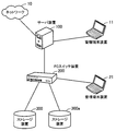
- the information processing system includes management terminal devices 11 and 21, a server device 100, a fiber channel (FC) switch device 200, and storage devices 300 and 300a.
- the management terminal device 11 is connected to the server device 100.
- the management terminal device 21 is connected to the FC switch device 200.
- the server device 100 is connected to the network 10.
- Management terminal devices 11 and 21 are computers operated by an administrator.
- the management terminal device 11 is for an administrator to input an instruction to the server device 100.
- the management terminal device 21 is for an administrator to input an instruction to the FC switch device 200.
- the server apparatus 100 is a server computer capable of operating a plurality of virtual machines.
- the server apparatus 100 manages activation and termination of a plurality of virtual machines.
- the server apparatus 100 makes the function of the virtual machine available to the client apparatus connected to the network 10 via the network 10.
- the FC switch device 200 is a switching machine that includes a plurality of FC interfaces and relays between the interfaces.
- the FC switch device 200 relays data communication between the server device 100 and the storage devices 300 and 300a.
- the FC switch device 200 receives an instruction from the management terminal device 21 and executes a management function on the FC switch device 200.
- the storage devices 300 and 300a are storage devices that store programs.
- the programs stored in the storage apparatuses 300 and 300a are OS startup programs (hereinafter referred to as OS programs).
- OS programs OS startup programs
- a virtual machine operating on the server apparatus 100 is activated by loading and executing an OS program stored in the storage apparatuses 300 and 300a.
- a program for starting an application other than the OS may be stored in the storage apparatuses 300 and 300a and used for starting an application in a virtual machine.
- FIG. 3 is a diagram illustrating a hardware example of the server device according to the second embodiment.
- the server device 100 includes a CPU (Central Processing Unit) board 101, a crossbar switch 102, a PCI Express (Peripheral Component Interconnect Express) controller 103, a SAS (Serial Attached SCSI (Small Computer System Interface)) interface 104, and an HDD (Hard Disk Drive). ) 105, FC interface 106, network interface 107, SVP (SerVice processor) 108, and disk drive 109.
- CPU Central Processing Unit
- PCI Express Peripheral Component Interconnect Express
- SAS Serial Attached SCSI (Small Computer System Interface) interface
- HDD Hard Disk Drive
- the CPU board 101 is an information processing unit including a CPU and a memory.
- the CPU board 101 includes a CPU 111, a RAM (Random Access Memory) 112, and an NVRAM 113.
- the CPU 111 is a computing device that executes a hypervisor program, an OS program, and an application program to realize a virtual machine and an application on the virtual machine.
- the CPU board 101 may include a plurality of CPUs.
- the RAM 112 is a volatile storage device that temporarily stores at least a part of a hypervisor program, an OS program, and an application program executed by the CPU 111.
- the RAM 112 temporarily stores at least a part of data used for the processing of the CPU 111.
- the CPU board 101 may include a plurality of RAMs.
- the NVRAM 113 is a non-volatile storage device that stores data used for processing of the hypervisor.
- the CPU board 101 may include a plurality of NVRAMs and flash ROMs.
- the server device 100 may include a plurality of CPU boards.
- the crossbar switch 102 relays data communication between the CPU board 101 and the PCI Express controller 103.
- the PCI Express controller 103 controls data communication between the crossbar switch 102, the SAS interface 104, the FC interface 106, and the network interface 107.
- the SAS interface 104 is connected to the HDD 105 and the disk drive 109, and controls data input / output with respect to the HDD 105 and the disk drive 109.
- the disk drive 109 may perform input / output control by encapsulating a SATA (Serial ATA) protocol.
- the HDD 105 is a non-volatile storage device that stores data used for hypervisor programs and hypervisor processing.
- the HDD 105 reads from and writes to the built-in magnetic disk in accordance with instructions from the CPU 111.
- the server device 100 may include a nonvolatile storage device (for example, SSD (Solid State Drive)) other than the HDD, or may include a plurality of storage devices.
- the hypervisor program executed on the CPU board 101 may be stored in the NVRAM 113.
- the FC interface 106 is an HBA that is connected to the switch device 200 and controls data communication with the switch device 200.
- the FC interface 106 includes an FC controller 114 and a memory 115.
- the FC controller 114 is an arithmetic device that controls the operation of the FC interface 106.
- the memory 115 stores data used for processing of the FC controller 114.
- the server apparatus 100 may include a plurality of FC controllers.
- the network interface 107 is connected to the network 10 and controls data communication with other devices via the network 10.
- the SVP 108 is a device for managing the server device 100.
- the SVP 108 is connected to the CPU board 101, the crossbar switch 102, and the PCI-Express controller 103 of the server apparatus by I2C or the like.
- the SVP 108 is connected to the management terminal device 11.
- the SVP 108 causes the management terminal device 11 to display a GUI (Graphical User Interface) for managing the server device 100.
- the administrator can issue an instruction to the server device 100 by operating the GUI with the management terminal device 11.
- the disk drive 109 is a drive device that reads programs and data recorded on the recording medium 12.
- a magnetic disk such as a flexible disk (FD) or HDD
- an optical disk such as a CD (Compact Disk) or a DVD (Digital Versatile Disk), or a magneto-optical disk (MO: Magneto-Optical disk).
- the disk drive 109 stores a program or data read from the recording medium 12 in the RAM 112 or the HDD 105 in accordance with a command from the CPU 111.
- FIG. 4 is a diagram illustrating a hardware example of the FC switch device according to the second embodiment.
- the FC switch device 200 includes a routing controller 201, a memory 202, an SVP 203, a crossbar switch 204, I / F (InterFace) controllers 205, 205a, 205b, 205c, 205d, 205e, buffers 206, 206a, 206b, 206c, 206d, 206e and ports 207, 207a, 207b, 207c, 207d, and 207e.
- I / F InterFace
- the I / F controller 205, the buffer 206, and the port 207 will be described below, but the I / F controllers 205a, 205b, 205c, 205d, and 205e, the buffers 206a, 206b, 206c, 206d, and 206e, and the ports 207a, 207b, The same applies to 207c, 207d, and 207e.
- the routing controller 201 controls data communication between a plurality of SANs (Storage Area Networks).
- the memory 202 stores data used for processing of the routing controller 201. For example, a routing table for connecting between SANs is stored.
- the SVP 203 is a device for managing the FC switch device 200.
- the SVP 203 is connected to the management terminal device 21.
- the SVP 203 causes the management terminal device 21 to display a GUI for managing the FC switch device 200.
- the administrator can operate the GUI with the management terminal device 21 and give an instruction to the FC switch device 200.
- the crossbar switch 204 relays data communication between devices via each port.
- the I / F controller 205 controls the data flow between the ports.
- the buffer 206 is a storage area for temporarily storing data in order to control the flow of data.
- the port 207 is an adapter for connecting to an external device.
- the port 207 is connected to the server apparatus 100 via an FC cable.
- the port 207c is connected to the storage apparatus 300 via an FC cable.
- the port 207d is connected to the storage apparatus 300a via an FC cable.
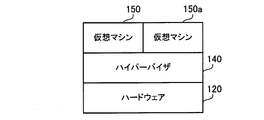
- FIG. 5 is a block diagram illustrating an arrangement example of virtual machines.
- the server apparatus 100 includes hardware 120, a hypervisor 140, and virtual machines 150 and 150a.
- the hardware 120 is a physical resource included in the server device 100.
- the hardware 120 includes a CPU board 101, a PCI Express controller 103, a SAS interface 104, an HDD 105, an FC interface 106, a network interface 107, and a disk drive 109.
- the hypervisor 140 implements a virtual machine.
- the hypervisor 140 assigns the hardware 120 to each virtual machine, and controls the start / stop of each virtual machine.
- the hypervisor 140 arbitrates access to the hardware 120 of each virtual machine so that the virtual machines can use the hardware 120 jointly. Further, the hypervisor 140 monitors the usage status of the hardware 120 assigned to each virtual machine.
- the virtual machines 150 and 150a are virtual machines realized on the server apparatus 100 by the hypervisor 140.
- the virtual machines 150 and 150a execute independent OSs.
- the virtual machines 150 and 150a can acquire the OS program from the storage apparatuses 300 and 300a when starting up. Specifically, the virtual machines 150 and 150a establish a connection with the storage apparatuses 300 and 300a using an activation code provided from the hypervisor 140.
- the virtual machines 150 and 150a load the OS program from a predetermined storage area of the storage apparatuses 300 and 300a.
- FIG. 6 is a block diagram illustrating an example of hardware allocation according to the second embodiment.
- the virtual machines 150 and 150a are realized by resources obtained by logically dividing the hardware 120 on the server apparatus 100.
- the CPU 111, the RAM 112, and the FC interface 106 are shown as main components included in the hardware 120.
- the CPU 111 is time-divided into CPU resources 11, l2, l3 and l4.
- the CPU resources l1 and l2 are allocated to the virtual machine 150
- the CPU resources l3 and l4 are allocated to the virtual machine 150a.
- the CPU may be divided into instruction units, processing units, and arithmetic circuit units.
- the RAM 112 is divided into RAM resources m1 and m2.
- the RAM resource m1 is allocated to the virtual machine 150
- the RAM resource m2 is allocated to the virtual machine 150a.
- the FC interface 106 is divided into FC interface resources n1 and n2.
- the FC interface resources n1 and n2 include resources obtained by time-sharing the FC controller 114.
- the FC interface resources n1 and n2 include resources obtained by dividing the memory 115 reserved for buffers.
- the FC interface resource n1 is assigned to the virtual machine 150
- the FC interface resource n2 is assigned to the virtual machine 150a. If the FC interface 106 is a physical HBA, the FC interface resources n1 and n2 are virtual HBAs realized on the physical HBA.
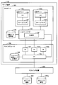
- FIG. 7 is a block diagram illustrating functions of the server device according to the second embodiment.
- the server apparatus 100 includes activation code storage units 130 and 160, a hypervisor 140, virtual machines 150 and 150a, a physical function (PF) 170, and virtual functions (VF) 180, 180a, and 180b.
- the functions of the activation code storage unit 130, the hypervisor 140, and the virtual machines 150 and 150a are realized on the server device 100 by the CPU 111 executing a predetermined program.
- the functions of the activation code storage unit 160, the PF 170, and the VFs 180, 180a, and 180b are realized on the server device 100 when the FC controller 114 executes a predetermined program. However, all or part of the functions of these units may be implemented with dedicated hardware.
- the activation code storage unit 130 stores a plurality of activation codes and an activation management table.
- the activation code is data describing processing and setting contents for the virtual machines 150 and 150a to establish connection with the storage apparatuses 300 and 300a and to acquire the OS program from the storage apparatuses 300 and 300a.
- the activation management table is data that defines the correspondence between the virtual machines 150 and 150a and the storage apparatuses 300 and 300a and the activation codes.
- the hypervisor 140 has a control unit 141.
- the control unit 141 acquires an activation code from the FC interface 106, duplicates the virtual machine 150 or 150a, and stores it in the activation code storage unit 130.
- the hypervisor 140 edits the activation code for each of the virtual machines 150 and 150a.
- the editing content is instructed from the management terminal device 11, for example.
- the control unit 141 selects an activation code corresponding to the virtual machines 150 and 150a from the activation code storage unit 130, and provides the selected activation code to the virtual machines 150 and 150a.
- the control unit 141 refers to the activation management table stored in the activation code storage unit 130 and selects an activation code corresponding to the virtual machines 150 and 150a.
- the virtual machine 150 has firmware 151 and an OS 152.
- the firmware 151 is software for loading the OS 152 program on the virtual machine 150 and starting the OS 152.
- the OS 152 is a basic program that operates on the virtual machine 150.
- the virtual machine 150a includes firmware 151a and an OS 152a.
- the firmware 151a corresponds to the firmware 151.
- the OS 152a corresponds to the OS 152.
- the activation code storage unit 160 stores an activation code.
- the activation code stored in the activation code storage unit 160 is preset by an administrator, for example.
- This activation code is a default activation code serving as a template for the activation code stored in the activation code storage unit 130.
- PF 170 is a data communication control module.
- the PF 170 implements VFs 180, 180a, and 180b on the FC interface 106.
- the PF 170 outputs the activation code stored in the activation code storage unit 160 to the hypervisor 140 in response to a request from the hypervisor 140.
- the PF 170 is an example of an access unit.
- VF 180, 180 a, and 180 b are data communication control modules generated by the PF 170.
- the VFs 180, 180a, 180b function as virtual adapters for the virtual machines 150, 150a.
- the virtual machines 150 and 150a can access the VFs 180, 180a, and 180b to share a single PF 170 and perform data communication with the external storage apparatuses 300 and 300a.
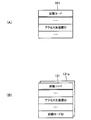
- FIG. 8 is a diagram illustrating an example of the data structure of the activation code.
- FIG. 8A shows an activation code 161 stored in the activation code storage unit 160.
- FIG. 8B shows activation codes 131 and 131 a stored in the activation code storage unit 130.
- the activation code 161 includes setting of an access destination device ID (IDentifier).
- IDentifier information for identifying the connection destination storage device is set.
- the identification information is, for example, a WWN corresponding to the connection destination storage apparatus.
- the WWN of the FC interface included in the storage apparatus 300 is set by default.
- the activation codes 131 and 131a include settings of an access destination device ID and an activation code ID.
- the access destination device ID corresponds to the access destination device ID set in the activation code 161.
- Separate access destination device IDs can be set in the activation codes 131 and 131a.
- the access destination device ID of the activation code 131 the WWN of the FC interface provided in the storage device 300 is set. Further, the WWN of the FC interface provided in the storage apparatus 300a is set in the access destination apparatus ID of the activation code 131a.
- the activation code ID is identification information for uniquely identifying the activation codes 131 and 131a. For example, an activation code ID “0” is set in the activation code 131. In addition, the activation code ID “1” is set in the activation code 131a.
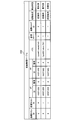
- FIG. 9 illustrates an exemplary data structure of the activation management table according to the second embodiment.
- the activation management table 132 is stored in the activation code storage unit 130.
- the activation management table 132 is updated by the control unit 141.
- the activation management table 132 includes items of physical host ID, virtual host ID, VF, PF, path, virtual port, activation code ID, activation designation, and allocation state. Information arranged in the horizontal direction of each item is associated with each other, and assignment of a VF and an activation code to one virtual machine is shown.
- VF identification information is set.
- the identification information of the VF is composed of a set of a device ID of the FC interface 106 that operates the VF and a number for identifying each VF on the PF.
- PF identification information is set.
- the identification information of the PF is composed of a set of a device ID of the FC interface 106 that operates the PF and a number for identifying each PF.
- device path information for the firmware to identify the PF and the VF in association with each other is set.
- identification information of a virtual port that can be used on the FC interface 106 is set.
- NPIV N Port ID Virtualization
- An activation code ID is set in the item of activation code ID.
- start designation item information indicating whether the OS is used to start the OS on the virtual machine is set (hereinafter, simply referred to as start-up, it is used for starting up the OS on the virtual machine). Show).
- start-up information indicating whether the OS is used to start the OS on the virtual machine is set (hereinafter, simply referred to as start-up, it is used for starting up the OS on the virtual machine). Show).
- the item indicating the allocation state information indicating whether or not the VF has been allocated to any virtual machine is set.
- the physical host ID is “0”
- the virtual host ID is “0”
- the ID for the VF is “10CF1223”
- the number is “0”
- the ID for the PF is “10CF1223”
- the number is “ 0 ”
- the path is“ / pci @ 0 / vdev0 / fc0 ”
- the virtual port is“ 0 ”
- the activation code ID is“ 0 ”
- the activation designation is“ for activation ”
- the allocation status is“ allocated ”. Is done.
- the virtual machine 150 (virtual host ID “0”) realized by the CPU board 101 (physical host ID “0”) is associated with the VF 180 (ID-number pair is “10CF1223-0”).
- the device path information for inputting / outputting to / from the VF 180 is “/ pci @ 0 / vdev0 / fc0”.
- the virtual port “0” of the PF 170 (ID-number pair is “10CF1223-0”) is associated with the VF 180.
- the VF 180 is designated for starting the OS on the virtual machine and has been assigned to the virtual machine 150.
- the physical host ID is “0”
- the virtual host ID is “1”
- the ID for the VF is “10CF1223”
- the number is “1”
- the ID for the PF is “10CF1223”
- the path is “/ pci @ 0 / vdev1 / fc1”
- the virtual port is “1”
- the activation code ID is “1”
- the activation designation is “for activation”
- the allocation state is “allocated”. Is set.
- the virtual machine 150a (virtual host ID “1”) realized by the CPU board 101 (physical host ID “0”) is associated with the VF 180a (ID-number pair is “10CF1223-1”).
- the device path information for inputting / outputting to / from the VF 180a is “/ pci @ 0 / vdev1 / fc1”.
- the virtual port “1” of the PF 170 is associated with the VF 180a.
- the VF 180a is designated for starting the OS on the virtual machine and has been assigned to the virtual machine 150a.
- the physical host ID is “0”
- the virtual host ID is “ ⁇ ” (hyphen)
- the ID for VF is “10CF1223”
- the number is “2”
- the ID for PF is “10CF1223”.
- the number is” 0 ", the path is"-"(hyphen), the virtual port is"-"(hyphen), the activation code ID is"-"(hyphen), the activation designation is" for non-activation ", and the allocation status is Information of “unallocated” is set.
- VF180b This indicates the information of VF180b. Specifically, it indicates that PF 170 (ID-number pair is “10CF1223-0”) is associated with VF180b (ID-number pair is “10CF1223-2”). Also, since the virtual host ID, path, virtual port, and activation code ID are not set ("-") and the allocation status is "unallocated", the VF 180b is not allocated to any virtual machine Indicates.
- Non-startup is set.
- VF 180b for starting a predetermined application to either of the virtual machines 150 and 150a.
- the setting of the activation designation item is “non-activation”.
- a VF used for activation and a VF used for other purposes can be mixed and used separately.
- the unallocated VF 180b for starting the OS on the virtual machine it is possible to further allocate to any one of the virtual machines 150 and 150a. For example, it is useful when you want to start by specifying a different activation code. Specifically, it is conceivable that the virtual machine 150 is newly associated with the unassigned VF 180b, the virtual port “2” of the PF 170, and the activation code 131a.
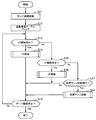
- FIG. 10 is a flowchart showing the overall processing of the second embodiment. In the following, the process illustrated in FIG. 10 will be described in order of step number.
- Step S11 The server device 100 is activated. Then, the hypervisor 140 is executed by the CPU board 101.
- the control unit 141 refers to the activation management table 132 stored in the activation code storage unit 130, and checks the correspondence between the virtual machine, the VF, and the virtual port of the PF. For example, when the existence of an assigned VF or PF cannot be confirmed, it is conceivable to notify the management terminal device 11 to that effect.
- Step S13 The control unit 141 determines whether a VF allocation instruction has been accepted.
- the VF assignment instruction is input to the control unit 141 when the administrator performs a predetermined operation on the management GUI using the management terminal device 11, for example. If a VF assignment instruction is accepted, the process proceeds to step S14. If a VF assignment instruction has not been received, the process proceeds to step S15.
- the VF assignment instruction includes information indicating a virtual machine to which a new VF is to be assigned, and information specifying the PF to be assigned and the number of VFs to be assigned. Designating a PF can be said to designate a set of VFs realized on the PF.
- Step S14 The control unit 141 performs VF allocation processing based on the VF allocation instruction. Then, the process proceeds to step S19.
- Step S15 The control unit 141 determines whether a VF release instruction has been received.
- the VF release instruction is input to the control unit 141 when the administrator performs a predetermined operation on the management GUI using the management terminal device 11, for example. If a VF release instruction is accepted, the process proceeds to step S16. If a VF release instruction has not been received, the process proceeds to step S17.
- the VF release instruction includes information indicating the VF to be released.
- Step S16 The control unit 141 performs VF release processing based on the VF release instruction. Then, the process proceeds to step S19.
- Step S17 The control unit 141 determines whether a virtual machine activation instruction has been received.
- the virtual machine activation instruction is input to the control unit 141 when the administrator performs a predetermined operation on the management GUI using the management terminal device 11, for example. If a virtual machine activation instruction is accepted, the process proceeds to step S18. If a virtual machine activation instruction has not been received, the process proceeds to step S19.
- the virtual machine activation instruction includes information indicating the virtual machine to be activated.
- Step S18 The control unit 141 activates the virtual machine based on the virtual machine activation instruction.
- Step S19 The hypervisor 140 determines whether or not the server device 100 is stopped. When the server apparatus 100 is stopped, the hypervisor 140 performs a stop process in preparation for the stop of the server apparatus 100 and ends the process. If the server apparatus 100 is not stopped, the process proceeds to step S13.
- the server apparatus 100 performs VF allocation / release and activation of the OS on the virtual machine according to various instructions.
- VF allocation process in step S14 will be described.
- FIG. 11 is a flowchart illustrating VF allocation processing according to the second embodiment. In the following, the process illustrated in FIG. 11 will be described in order of step number.
- the control unit 141 acquires a VF allocation instruction.
- the VF allocation instruction includes, for example, an instruction to allocate two VFs for activation from the PF 170 to the virtual machines 150 and 150a.
- the control unit 141 identifies the PF and the requested number of VFs (in this case, 2) included in the VF allocation instruction.
- Step S22 The control unit 141 confirms the number of VFs configured on the PF from the specified PF, and loads the activation code. For example, the control unit 141 loads the activation code 161 from the PF 170. At this time, the activation code 161 stored in the activation code storage unit 160 is read by the PF 170 and output to the control unit 141.
- the control unit 141 refers to the activation management table 132 and acquires the number of unallocated VFs for the PF. For example, 3 is acquired as the number of allocated VFs for the PF 170 (for example, the allocation states of the VFs 180, 180a, and 180b are all “unallocated”).
- Step S24 The control unit 141 compares the number of unallocated VFs with the number of requested VFs.
- Step S25 The controller 141 determines whether or not the requested VF can be allocated. A case where allocation is possible is a case where the number of unallocated VFs is equal to or greater than the number of requested VFs. On the other hand, the case where allocation is impossible is the case where the number of unallocated VFs is smaller than the required number of VFs. If the requested VF can be assigned, the process proceeds to step S27. If the requested VF cannot be allocated, the process proceeds to step S26. In addition, the control part 141 selects VF to allocate, when allocation is possible. For example, the VF to be assigned in ascending order of the VF identification information is selected. For example, VF180, 180a is selected as an allocation target among VF180, 180a, 180b.
- Step S26 The control unit 141 notifies the management terminal device 11 that a VF cannot be assigned from the requested PF.
- the administrator can confirm the notification and make a VF allocation request specifying another PF again.
- Step S27 The control unit 141 duplicates the activation code loaded from the PF in step S22 by the number of requested VFs. At this time, the control unit 141 adds an activation code ID to the duplicated activation code. For example, the activation codes 161 loaded from the PF 170 are copied by the number of requested VFs “2” to generate the activation codes 131 and 131a. Then, the control unit 141 adds the activation code ID “0” to the activation code 131, for example. The activation code ID “1” is added to the activation code 131a.
- Step S28 The control unit 141 updates the activation code for each VF according to an instruction from the management terminal device 11. Specifically, the control unit 141 changes the access destination device IDs of the activation codes 131 and 131a to the setting contents designated by the administrator. For example, the access destination device ID of the activation code 131 is changed to the WWN of the storage device 300. Further, the access destination device ID of the activation code 131a is changed to the WWN of the storage device 300a.
- the access destination device may be specified by topology (connection form) information in addition to the access destination device ID.
- Step S29 Upon receiving an instruction for completion of editing from the management terminal device 11, the control unit 141 stores the changed activation code in the activation code storage unit 130. For example, the control unit 141 stores the activation codes 131 and 131a in the activation code storage unit 130.
- the control unit 141 updates the activation management table 132.
- the control unit 141 includes a virtual machine 150 (virtual host ID “0”), a VF 180 (ID and number pair “10CF1223-0”), a virtual port “0” of the PF 170, and an activation code 131 (activation code). ID “0”) and a path are set.
- the control unit 141 also includes a virtual machine 150a (virtual host ID “1”), a VF 180a (ID and number pair “10CF1223-1”), a virtual port “1” of the PF 170, and an activation code 131a (activation code). ID “1”) is associated and a path is set. Further, for each of these records, the activation designation is set to “for activation” and the allocation state is set to “allocated”. Then, the control unit 141 notifies the management terminal device 11 of the completion of allocation.
- control unit 141 edits the activation management table 132 and assigns the VFs 180 and 180a to the virtual machines 150 and 150a.
- the VF allocation instruction may include an access destination device ID desired to be set for each VF and other setting information.
- the control unit 141 can set the access destination apparatus ID specified by the VF allocation instruction in the activation codes 131 and 131a. For this reason, the operation of the administrator in step S28 can be omitted.
- step S30 the virtual machine 150 and the VF 180 are associated with each other and the virtual machine 150a and the VF 180a are associated with each other (in the ascending order of IDs).
- the present invention is not limited to such a method.
- the virtual machine 150 and the VF 180a may be associated with each other, and the virtual machine 150a and the VF 180 may be associated with each other.
- the virtual ports of the PF 170 may be allocated by selecting unassigned virtual ports in ascending order of IDs, for example.
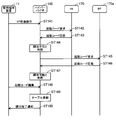
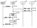
- FIG. 12 is a sequence diagram illustrating a VF allocation process according to the second embodiment. In the following, the process illustrated in FIG. 12 will be described in order of step number. Note that immediately before step ST101 shown below, it is assumed that the allocation status of the VFs 180, 180a, and 180b is “unallocated” in the activation management table 132 stored in the activation code storage unit 130.
- the management terminal apparatus 11 transmits a VF allocation instruction to the hypervisor 140.
- the VF assignment instruction includes an instruction to assign two VFs from the PF 170 to the virtual machines 150 and 150a.
- Step ST102 Upon receiving the VF assignment instruction, the hypervisor 140 requests the activation code 161 from the designated PF 170. (Step ST ⁇ b> 103) In response to a request from the hypervisor 140, the PF 170 acquires the activation code 161 from the activation code storage unit 160 and outputs it to the hypervisor 140.
- the hypervisor 140 confirms the number of VFs configured on the PF based on the activation code 161.
- the hypervisor 140 refers to the activation management table 132 stored in the activation code storage unit 130 and determines that the virtual machines 150 and 150a can be allocated to the unallocated VFs 180, 180a, and 180b on the PF 170.
- Step ST105 The activation code 161 is duplicated to generate activation codes 131 and 131a.
- the hypervisor 140 adds an activation code ID to the activation codes 131 and 131a.
- the hypervisor 140 displays the contents of the activation codes 131 and 131a on the management terminal device 11 and allows editing from the GUI on the management terminal device 11.
- the administrator inputs the editing contents of each activation code from the GUI.
- the management terminal device 11 transmits the edited content for the activation codes 131 and 131a to the hypervisor 140.
- the management terminal device 11 receives the input of the completion of editing, the management terminal device 11 notifies the hypervisor 140 of it.
- Step ST106 The hypervisor 140 reflects the edited contents in the activation codes 131 and 131a and stores them in the activation code storage unit 130. Then, the hypervisor 140 updates the activation management table 132.
- Step ST107 The hypervisor 140 notifies the management terminal device 11 of the completion of allocation. In this way, the hypervisor 140 acquires the activation code 161 from the PF 170, and generates the activation codes 131 and 131a using the activation code 161 as a template. The hypervisor 140 associates the virtual machines 150 and 150a, the VFs 180 and 180a, the virtual ports of the PF 170 and the activation codes 131 and 131a. The hypervisor 140 manages the correspondence relationship using the activation management table 132.
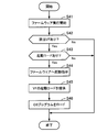
- FIG. 13 is a flowchart illustrating VF release processing according to the second embodiment. In the following, the process illustrated in FIG. 13 will be described in order of step number.
- Step S31 The control unit 141 identifies the VF to be deallocated from the content of the deallocation instruction. For example, the control unit 141 identifies the VF 180 as a deallocation target.
- Step S32 The control unit 141 instructs the VF to be deallocated and the PF to which the VF belongs to release resources reserved for communication. For example, the control unit 141 instructs the PF 170 and the VF 180 to release resources.
- Step S33 The control unit 141 updates the activation management table 132. Specifically, the setting values of the items of the virtual host ID, path, virtual port, and activation code ID set in the VF 180 record are cleared. Also, non-startup is set in the start specification item. Furthermore, the allocation status item is set to “unallocated”.
- FIG. 14 is a sequence diagram illustrating VF release processing according to the second embodiment. In the following, the process illustrated in FIG. 14 will be described in order of step number. Note that immediately before step ST111 shown below, in the activation management table 132 stored in the activation code storage unit 130, the virtual machine 150 (virtual host ID “0”) and VF180 (the combination of the VF ID and number is “10CF1223-”). 0 ”) and the activation code 131 (activation code ID“ 0 ”) are associated with each other.
- Step ST111 The management terminal device 11 transmits a VF cancellation instruction to the hypervisor 140. It is assumed that the VF cancellation instruction includes an instruction to cancel the allocation of the VF 180. (Step ST112) Upon receiving the VF release instruction, the hypervisor 140 transmits an instruction to release the secured resources to the VF 180 that has received the release instruction and the PF 170 to which the VF 180 belongs.
- Step ST113 In response to the resource release instruction, the PF 170 releases the storage area secured in the memory 115 for communication using the VF 180.
- the VF 180 similarly releases the storage area secured in the memory 115 for communication.
- the PF 170 responds to the hypervisor 140 that the resource release has been completed.
- Step ST114 The hypervisor 140 updates the activation management table 132 stored in the activation code storage unit 130. Specifically, information on the virtual machine 150, the path, the virtual port of the PF 170 and the activation code 131 associated with the VF 180 is deleted from the activation management table 132.
- Step ST115 The hypervisor 140 notifies the management terminal device 11 that the VF cancellation corresponding to the VF cancellation instruction has been completed. In this way, the hypervisor 140 deallocates the VF 180.
- the hypervisor 140 updates the setting content of the activation management table 132 and manages the VF 180 as an unallocated state. Thereby, the VF 180 can be assigned to other virtual machines, and the state of the VF 180 can be appropriately managed.
- step ST114 the activation code 131 is left without being deleted from the activation code storage unit 130.
- the activation code 131 may be deleted from the activation code storage unit 130.
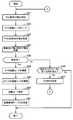
- FIG. 15 is a flowchart illustrating virtual machine activation processing according to the second embodiment. In the following, the process illustrated in FIG. 15 will be described in order of step number.
- Step S41 Upon receiving the virtual machine activation instruction, the control unit 141 causes the CPU 111 to execute the firmware of the designated virtual machine. For example, the control unit 141 receives an activation instruction for the virtual machines 150 and 150a. Then, the firmware 111, 151a is executed by the CPU 111. As a result, the functions of the firmware 151 and 151a are realized on the server device 100, and the virtual machines 150 and 150a are started.
- Step S42 The control unit 141 refers to the activation management table 132 stored in the activation code storage unit 130 and determines whether there is a VF assigned to the virtual machine to be activated. If it exists, the process proceeds to step S43. If it does not exist, the process ends. For example, the control unit 141 confirms that the VFs 180 and 180a have been assigned to the virtual machines 150 and 150a to be activated.
- Step S43 The control unit 141 refers to the activation management table 132 and determines whether there is an activation code assigned to the virtual machine to be activated. If it exists, the process proceeds to step S44. If it does not exist, the process ends. For example, the control unit 141 confirms that the activation codes 131 and 131a are assigned to the virtual machines 150 and 150a to be activated.
- Step S44 The control unit 141 instructs the firmware realized on the server device 100 in step S41 to start the virtual machine. Then, the firmware requests the control unit 141 for an activation code for loading the OS program. For example, the firmware 151 or 151 a that has received the activation instruction requests the control unit 141 for an activation code.
- Step S45 Upon receiving the request, the control unit 141 refers to the activation management table 132 stored in the activation code storage unit 130, and identifies the activation code associated with each virtual machine. For example, the activation code 131 is specified for the virtual machine 150 and the activation code 131a is specified for the virtual machine 150a.
- the control unit 141 provides the activation code 131 to the firmware 151.
- the control unit 141 provides the activation code 131a to the firmware 151a.
- Step S46 The firmware 151, 151a establishes a connection with the storage apparatus 300, 300a based on the activation code acquired from the control unit 141 and the virtual port, and loads the OS program from each apparatus. For example, the firmware 151 establishes a connection with the storage device 300 corresponding to the WWN specified by the access destination device ID of the activation code 131 and loads the OS program from the storage device 300. In addition, the firmware 151a establishes a connection with the storage apparatus 300a corresponding to the WWN specified by the access destination apparatus ID of the activation code 131a, and loads the OS program from the storage apparatus 300a. Then, the firmware 151, 151a starts the OS 152, 152a by causing the CPU 111 to execute the loaded OS program.
- control unit 141 acquires the start codes 131 and 131a stored in the start code storage unit 130 and provides them to the virtual machines 150 and 150a.
- control part 141 may stop the firmware 151,151a.
- control unit 141 may notify the management terminal apparatus 11 of the reason for ending the process (for example, there is no assigned VF or activation code).
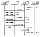
- FIG. 16 is a sequence diagram illustrating virtual machine activation processing according to the second embodiment. In the following, the process illustrated in FIG. 16 will be described in order of step number.
- the management terminal apparatus 11 transmits a virtual machine activation instruction to the hypervisor 140.
- the virtual machine activation instruction includes information specifying the virtual machines 150 and 150a.
- Step ST122 Upon receiving the virtual machine activation instruction, the hypervisor 140 detects that the virtual machines 150 and 150a are designated. Then, the hypervisor 140 refers to the activation management table 132 stored in the activation code storage unit 130 and confirms that the VF 180 and the activation code 131 are associated with the virtual machine 150. Then, the hypervisor 140 outputs an activation instruction to the virtual machine 150. As a result, the firmware 151 starts to be executed on the server device 100, and the virtual machine 150 starts to be started.
- Step ST123 The hypervisor 140 refers to the activation management table 132 and confirms that the VF 180a and the activation code 131a are associated with the virtual machine 150a. Then, the hypervisor 140 outputs an activation instruction to the virtual machine 150a. Thereby, execution of the firmware 151a is started on the server apparatus 100, and the activation of the virtual machine 150a is started.
- Step ST124 The virtual machine 150 requests the hypervisor 140 for an activation code.
- Step ST125 The hypervisor 140 acquires the activation code 131 from the activation code storage unit 130 and provides it to the virtual machine 150.
- Step ST126 The virtual machine 150a requests an activation code from the hypervisor 140.
- Step ST127 The hypervisor 140 acquires the activation code 131a from the activation code storage unit 130 and provides it to the virtual machine 150a.
- Step ST1228 The virtual machine 150 tries to connect to the storage apparatus 300 based on the access destination apparatus ID indicated by the activation code 131.
- the hypervisor 140 refers to the activation management table 132, assigns the connection to the VF 180, and further associates it with the virtual port “0” of the PF 170. That is, the virtual machine 150 establishes a connection with the storage apparatus 300 via the virtual port “0” of the VF 180 and the PF 170. Then, the virtual machine 150 requests the OS program from the storage apparatus 300.
- Step ST129 The storage apparatus 300 transmits the OS program to the virtual machine 150.
- the hypervisor 140 associates the OS program received via the virtual port “0” of the PF 170 with the VF 180 and outputs the OS program to the virtual machine 150.
- the virtual machine 150 receives the OS program, the virtual machine 150 activates the OS 152.
- Step ST130 The virtual machine 150a attempts to connect to the storage apparatus 300a based on the access destination apparatus ID indicated by the activation code 131a.
- the hypervisor 140 refers to the activation management table 132, assigns the connection to the VF 180a, and further associates it with the virtual port “1” of the PF 170.
- the virtual machine 150a establishes a connection with the storage apparatus 300a via the virtual port “1” of the VF 180a and the PF 170.
- the virtual machine 150a requests an OS program from the storage apparatus 300a.
- Step ST131 The storage apparatus 300a transmits the OS program to the virtual machine 150a.
- the hypervisor 140 associates the OS program received via the virtual port “1” of the PF 170 with the VF 180a and outputs the OS program to the virtual machine 150a.
- the virtual machine 150a receives the OS program, the virtual machine 150a starts the OS 152a.
- the hypervisor 140 manages the correspondence between the virtual ports of the virtual machines 150 and 150a, the VFs 180 and 180a, and the PF 170 and the activation codes 131 and 131a using the activation management table 132.
- the activation codes 131 and 131a stored in the activation code storage unit 130 are virtualized instead of the activation code 161 stored in the activation code storage unit 160 on the FC interface 106. To the machines 150 and 150a.
- the virtual machines 150 and 150a can establish connections with the storage apparatuses 300 and 300a using the separate activation codes 131 and 131a, respectively. If different storage devices are specified as access destinations in the activation codes 131 and 131a, OS programs can be loaded from separate storage devices, and separate OS programs can be activated on the virtual machines 150 and 150a. That is, the access destination storage apparatuses 300 and 300a when the OS program is started can be switched for each of the virtual machines 150 and 150a.
- FIG. 9 an example in which the activation codes 131 and 131a are associated with the virtual machine 150 is shown.
- which of the activation codes 131 and 131a is used to activate the virtual machine 150 is set, for example, in the firmware 151, and the firmware 151 instructs the hypervisor 140 when the virtual machine 150 is activated.
- the OS to be booted on the virtual machine 150 can be selected when the virtual machine 150 is booted.
- the activation of the OS program has been mainly described, but it is not limited to the activation of the OS program.
- the storage apparatus that loads the application program can be switched for each virtual machine.
- the method of allocating PF and VF on one FC interface to a plurality of virtual machines executed on one CPU board is exemplified.
- the server apparatus 100 may be provided with a plurality of CPU boards and a plurality of FC interfaces.
- the virtual machine, PF, and VF between one CPU board and one FC interface can be associated in the same manner as in the second embodiment.
- VFs may be allocated from a plurality of FC interfaces to a plurality of virtual machines on one CPU board. Therefore, in the third embodiment, a method of allocating VF from different FC interfaces to each virtual machine in a server apparatus having a plurality of CPU boards and a plurality of FC interfaces will be described.
- the overall configuration of the information processing system according to the third embodiment is the same as the overall configuration of the information processing system according to the second embodiment described with reference to FIG.
- the hardware configuration of the server device according to the third embodiment is the same as the hardware configuration of the server device 100 according to the second embodiment described with reference to FIG.
- the same reference numerals as those of the apparatus 100 are used).
- the server apparatus 100 according to the third embodiment further includes a CPU board 101a and an FC interface 106a.
- the hardware configuration of the CPU board 101a is the same as that of the CPU board 101.
- the hardware configuration of the FC interface 106 a is the same as that of the FC interface 106.
- the hardware configuration of the FC switch device according to the third embodiment is the same as the hardware configuration of the FC switch device 200 according to the second embodiment described with reference to FIG. Is represented by the same symbol as the FC switch device 200).
- FIG. 17 is a block diagram illustrating functions of the server device according to the third embodiment.
- the server device 100 includes activation code storage units 130 and 130a, hypervisors 140 and 140a, virtual machines 150, 150a and 150b, activation code storage units 160 and 160a, PFs 170 and 170a, and VFs 180, 180a, 180c and 180d.
- the activation code storage unit 130, the hypervisor 140, and the virtual machines 150 and 150a are realized on the server device 100 by the CPU 111 executing a predetermined program.
- the activation code storage unit 130a, the hypervisor 140a, and the virtual machine 150b are realized on the server device 100 when the CPU on the CPU board 101a executes a predetermined program.
- the activation code storage unit 160, the PF 170, and the VFs 180 and 180a are realized on the server device 100 when the FC controller 114 executes a predetermined program.
- the activation code storage unit 160a, the PF 170a, and the VFs 180c and 180d are realized on the server device 100 when the FC controller on the FC interface 106a executes a predetermined program.
- all or part of the functions of these units may be realized by dedicated hardware.
- the activation code storage unit 130a corresponds to the activation code storage unit 130.
- the hypervisor 140a corresponds to the hypervisor 140.
- the hypervisor 140a has a control unit 141a.
- the control unit 141a corresponds to the control unit 141.
- the control units 141 and 141a can communicate with each other.
- the control units 141 and 141a synchronize the activation codes stored in the activation code storage units 130 and 130a and the setting contents of the activation management table.
- the control units 141 and 141a give activation code identification information unique to the activation code storage units 160 and 160a to the activation code.
- the virtual machine 150b corresponds to the virtual machines 150 and 150a.
- the virtual machine 150b constitutes one logical virtual machine together with the virtual machine 150a. That is, one virtual machine that combines the virtual machines 150a and 150b is realized across the CPU boards 101 and 101a.
- the hypervisors 140 and 140a synchronize predetermined data with each other so that the virtual machines 150a and 150b can be used as one virtual machine from a client device.
- the activation code storage unit 160a corresponds to the activation code storage unit 160.
- the PF 170a corresponds to the PF 170.
- the PF 170 a is connected to the FC switch device 200.
- VF 180c and 180d correspond to VF 180 and 180a.
- the VFs 180c and 180d are data communication control modules generated by the PF 170a.
- the virtual machines 150, 150a, and 150b share the single PF 170a by accessing the VFs 180c and 180d, and can perform data communication with the external storage apparatuses 300 and 300a.
- the VF 180b of the FC interface 106 is not shown (assuming that the VF 180b has already been assigned or does not exist).
- FIG. 18 is a diagram illustrating an example of a data structure of the activation management table according to the third embodiment.
- the activation management table 132a corresponds to the activation management table 132.
- the contents set for each item are the same as those in the activation management table 132.
- VF cannot be allocated from the PF 170 when the virtual machine 150a is started.
- One example is a case where both the VFs 180 and 180a have been allocated to the virtual machine 150 and no other unallocated VF exists on the PF 170.
- the activation management table 132a exemplifies the setting in that case.
- the VF 180, 180a (the combination of the VF ID and number is “10CF1223-0” and “10CF1223-1”) has been allocated. Both the VFs 180 and 180a are “for start-up”. Two types of activation codes with activation code IDs “0” and “1” are associated with each of the VFs 180 and 180a, and the virtual machine 150 can be activated by selecting one of the activation codes at the time of activation. Yes.
- the activation management table 132a also shows the allocation status for the virtual machine 150b. Specifically, for the virtual machine 150b (virtual host ID “0”) on the CPU board 101a (physical host ID “1”), the VF 180c on the PF 170a (the combination of the VF ID and number is “10CF1223-0”) ) Is assigned. Further, the virtual port “0” of the PF 170a is associated with the VF 180c. Furthermore, the activation code ID “2” is associated with the virtual machine 150b.
- the control unit 141 detects the PF 170a having the same ID and receives the unallocated VF 180d on the PF 170a even when receiving the VF allocation instruction specifying the PF 170 in a state where all the VFs on the PF 170 are already allocated. Assign to 150a.
- VF 180d (a set of VF ID and number is “10CF1223-1”) is assigned. Further, the virtual port “1” of the PF 170a is associated with the VF 180d. The association line between the hypervisor 140 and the VF 180d in FIG. 17 indicates this allocation relationship. Furthermore, the activation code ID “3” is associated with the virtual machine 150a.
- the procedure of the overall process, the deallocation process, and the virtual machine activation process is the same as the procedure of the overall process, the deallocation process, and the virtual machine activation process of the second embodiment described with reference to FIGS. Since there is, explanation is omitted.
- FIG. 19 is a flowchart illustrating VF allocation processing according to the third embodiment. In the following, the process illustrated in FIG. 19 will be described in order of step number.
- the control unit 141 acquires a VF allocation instruction.
- the VF assignment instruction includes information for designating a virtual machine, a PF to be assigned to the virtual machine for activation, and the number of VFs to be assigned (number of requested VFs).
- the control unit 141 specifies the PF and the number of requested VFs from the VF allocation instruction.
- Step S52 The control unit 141 confirms the number of VFs configured on the PF from the specified PF, and loads the activation code.
- Step S53 The control unit 141 refers to the activation management table 132a stored in the activation code storage unit 130, and acquires the number of unallocated VFs for the PF.
- Step S54 The control unit 141 compares the number of unallocated VFs with the number of requested VFs.
- Step S55 The control unit 141 determines whether the requested number of VFs can be allocated from the designated PF. If allocation is possible, the process proceeds to step S58. If assignment is impossible, the process proceeds to step S56.
- Step S56 The control unit 141 refers to the activation management table 132a and determines whether or not a PF having the same ID exists on another FC interface. If a PF with the same ID exists, the process proceeds to step S57. If there is no PF with the same ID, the management terminal apparatus 11 is notified that the VF cannot be allocated, and the process is terminated. For example, the PF 170 a exists as a PF having the same ID (“10CF1223”) as the PF 170.
- the control unit 141 makes a determination in step S56 except for the PF for which the processes in steps S51 to S55 have been executed.
- Step S57 The control unit 141 changes the PF designation in the VF allocation instruction acquired in Step S51 to the PF detected in Step S56. As a result, a separate PF (for example, PF 170a instead of PF 170) is specified in the VF allocation instruction. Then, the process proceeds to step S51. Note that the control unit 141 discards the activation code acquired in step S52.
- Step S58 The control unit 141 duplicates the activation code loaded from the PF in step S52 by the number of requested VFs.
- the control unit 141 adds the activation code ID to the copied activation code.
- Step S ⁇ b> 59 The control unit 141 updates the setting contents of the access destination device ID of the activation code for each VF according to an instruction from the management terminal device 11.
- Step S ⁇ b> 60 Upon receiving an editing completion instruction from the management terminal device 11, the control unit 141 stores the changed activation code in the activation code storage unit 130. And the control part 141 transmits the starting code preserve
- Step S61 The control unit 141 updates the activation management table 132a.
- the control unit 141 also transmits the update contents to the control unit 141a, updates the activation management table stored in the activation code storage unit 130a, and synchronizes the activation management table.
- the control unit 141 when the control unit 141 receives a VF allocation instruction, even if a VF cannot be allocated from the designated PF, if there is another PF with the same ID, an unallocated VF is assigned from the PF. Discover and assign to virtual machines.
- the reason for detecting the PF with the same ID is that the ID indicates the ID assigned to the device. If the ID is the same, the functions of the PF are considered to be the same. That is, when the VF cannot be allocated from the PF designated by the VF allocation instruction, the control unit 141 tries to allocate the VF from another PF having the same function as the PF.
- the VF allocation instruction may include an access destination device ID desired to be set for each VF and other setting information.
- the control unit 141 can set the access destination device ID specified by the VF assignment instruction as the activation code. For this reason, the administrator's operation in step S59 can be omitted.
- FIG. 20 is a sequence diagram illustrating a VF allocation process according to the third embodiment.
- the process illustrated in FIG. 20 will be described along with step numbers. Note that immediately before step ST141 shown below, it is assumed that the VFs 180 and 180a have been assigned to the virtual machine 150, and the VF 180c has been assigned to the virtual machine 150b. Assume that no other unallocated VF exists in the PF 170. In the activation management table 132a, it is assumed that the VF 180d is in an “unallocated” state.
- Step ST141 The management terminal apparatus 11 transmits a VF allocation instruction to the hypervisor 140. It is assumed that the VF allocation includes an instruction to allocate one VF for activation from the PF 170 to the virtual machine 150a.
- Step ST142 Upon receiving the VF assignment instruction, the hypervisor 140 requests the designated PF 170 to transmit the activation code 161.
- Step ST143 In response to the request from the hypervisor 140, the PF 170 acquires the activation code 161 from the activation code storage unit 160 and outputs the activation code 161 to the hypervisor 140.
- the hypervisor 140 checks the number of VFs configured on the PF based on the activation code 161.
- the hypervisor 140 refers to the activation management table 132 a stored in the activation code storage unit 130, and determines that there is no unallocated VF in the PF 170 and that a new VF cannot be allocated from the PF 170. .
- Step ST145 When the hypervisor 140 detects the PF 170a having the same ID as the PF 170, the hypervisor 140 requests the PF 170a to transmit an activation code.
- Step ST146 In response to a request from the hypervisor 140, the PF 170a obtains the activation code from the activation code storage unit 160a and outputs it to the hypervisor 140.
- the hypervisor 140 checks the number of VFs configured on the PF 170a based on the activation code received from the PF 170a.
- the hypervisor 140 refers to the activation management table 132a and determines that the VF 180d in the PF 170a has not been allocated and that VF allocation is possible.
- the hypervisor 140 adds the activation code ID “3” to the activation code received from the PF 170a (the activation code need not be duplicated because the number of requested VFs is one).
- the activation code with the activation code ID “3” is referred to as an activation code 131a.
- the hypervisor 140 receives the editing of the activation code 131a from the management terminal device 11.
- the WWN of the storage apparatus 300a is set as the access destination apparatus ID of the activation code 131a.
- the management terminal device 11 receives an input of editing completion by the administrator, the management terminal device 11 notifies the hypervisor 140 of the input.
- the hypervisor 140 reflects the edited content in the activation code 131a and stores it in the activation code storage unit 130.
- the hypervisor 140 sets the correspondence relationship between the virtual port 150 of the virtual machine 150a and the PF 170a, the VF 180d, and the activation code 131a in the activation management table 132a for activation.
- the hypervisor 140 communicates with the hypervisor 140a to synchronize the saved activation code 131a with the updated contents of the activation management table 132a.
- Step ST150 The hypervisor 140 notifies the management terminal device 11 of completion of allocation. In this way, the hypervisor 140 detects the unallocated VF from the PF 170a having the same ID as the PF 170 and associates it with the virtual machine 150a even if there is no unallocated VF in the designated PF 170.
- FIG. 21 is a sequence diagram illustrating virtual machine activation processing according to the third embodiment. In the following, the process illustrated in FIG. 21 will be described in order of step number.
- the management terminal device 11 transmits a virtual machine activation instruction to the hypervisor 140.
- the virtual machine activation instruction includes information specifying the virtual machines 150 and 150a.
- Step ST152 Upon receiving the virtual machine activation instruction, the hypervisor 140 detects that the virtual machines 150 and 150a are designated. Then, the hypervisor 140 refers to the activation management table 132 a stored in the activation code storage unit 130, and associates two activation codes including the activation VFs 180 and 180 a and the activation code 131 with the virtual machine 150. Make sure that Then, the hypervisor 140 outputs an activation instruction to the virtual machine 150. Thereby, execution of the firmware 151 is started on the server device 100.
- Step ST153 The hypervisor 140 refers to the activation management table 132a and confirms that the activation VF 180d and the activation code 131a are associated with the virtual machine 150a. Then, the hypervisor 140 outputs an activation instruction to the virtual machine 150a. Thereby, execution of the firmware 151a is started on the server device 100.
- Step ST154 The virtual machine 150 requests an activation code from the hypervisor 140.
- the activation management table 132a two activation codes including the activation code 131 are associated with the virtual machine 150.
- the virtual machine 150 requests the hypervisor 140 by specifying the activation code 131 among them.
- the activation code may be selected by the firmware of the virtual machine 150.
- Step ST155 The hypervisor 140 acquires the activation code 131 from the activation code storage unit 130 and provides it to the virtual machine 150.
- Step ST156 The virtual machine 150a requests an activation code from the hypervisor 140.
- Step ST157 The hypervisor 140 acquires the activation code 131a from the activation code storage unit 130 and provides it to the virtual machine 150a.
- Step ST158 The virtual machine 150 attempts to connect to the storage apparatus 300 based on the access destination apparatus ID indicated by the activation code 131.
- the hypervisor 140 refers to the activation management table 132a, assigns the connection to the VF 180, and further associates it with the virtual port “0” of the PF 170. That is, the virtual machine 150 establishes a connection with the storage apparatus 300 via the virtual port “0” of the VF 180 and the PF 170. Then, the virtual machine 150 requests the OS program from the storage apparatus 300.
- Step ST159 The storage apparatus 300 transmits the OS program to the virtual machine 150.
- the hypervisor 140 associates the OS program received via the virtual port “0” of the PF 170 with the VF 180 and outputs the OS program to the virtual machine 150.
- the virtual machine 150 receives the OS program, the virtual machine 150 activates the OS 152.
- Step ST160 The virtual machine 150a tries to connect to the storage apparatus 300a based on the access destination apparatus ID indicated by the activation code 131a.
- the hypervisor 140 refers to the activation management table 132a, assigns the connection to the VF 180d, and further associates it with the virtual port “0” of the PF 170a. That is, the virtual machine 150a establishes a connection with the storage apparatus 300a via the virtual port “0” of the VF 180d and the PF 170a. Then, the virtual machine 150a requests an OS program from the storage apparatus 300a.
- Step ST161 The storage apparatus 300a transmits an OS program to the virtual machine 150a.
- the hypervisor 140 associates the OS program received via the virtual port “0” of the PF 170a with the VF 180d and outputs the OS program to the virtual machine 150a.
- the virtual machine 150a receives the OS program, the virtual machine 150a starts the OS 152a.
- the hypervisor 140 can assign VFs from the FC interfaces 106 and 106a to the virtual machines 150 and 150a on the CPU board 101. Thereby, the freedom degree of VF allocation with respect to each virtual machine can be improved.
- VF when a VF cannot be assigned from a designated PF to the virtual machine 150a, there may be a virtual machine 150b that constitutes one virtual machine together with the virtual machine 150a. In that case, the PF 170a associated with the virtual machine 150b may be preferentially selected and an unallocated VF may be detected.
- the hypervisor manages the correspondence between virtual ports of virtual machines, VFs, and PFs and activation codes in accordance with instructions from the management terminal device 11.
- this may be performed by the switch device 200.
- the administrator can operate the management terminal device 21 and instruct to start the virtual machine via the FC switch device 200.
- such a function will be described.
- the overall configuration of the information processing system according to the fourth embodiment is the same as the overall configuration of the information processing system according to the second embodiment described with reference to FIG.
- the SVP 108 of the server apparatus 100 and the SVP 203 of the FC switch apparatus 200 are connected by a management LAN (Local Area Network).
- LAN Local Area Network
- the hardware configuration of the server device according to the fourth embodiment is the same as the hardware configuration of the server device 100 according to the second embodiment described with reference to FIG. The same reference numerals as those of the apparatus 100 are used).
- the hardware configuration of the FC switch device according to the fourth embodiment is the same as the hardware configuration of the FC switch device 200 according to the second embodiment described with reference to FIG. Is represented by the same symbol as the FC switch device 200).
- FIG. 22 is a block diagram illustrating functions of the FC switch device according to the fourth embodiment.
- the FC switch device 200 includes an activation management information storage unit 210 and a control unit 220.
- the functions of these units are realized on the FC switch device 200 by the SVP 203 executing a predetermined program. However, all or part of the functions of these units may be implemented with dedicated hardware.
- the activation management information storage unit 210 stores an activation management table.
- An example of the data structure of the activation management table is the same as that of the activation management table 132 described with reference to FIG.
- the control unit 220 instructs the hypervisor 140 to copy / edit the activation code. Further, the control unit 220 updates the activation management table stored in the activation management information storage unit 210. Specifically, the control unit 220 sets the correspondence relationship between the newly allocated virtual machine, the activation code, the virtual ports of the VFs 180, 180a, 180b, and the PF 170 in the activation management table.
- the control unit 220 executes processes related to the activation management table.
- control unit 220 executes the entire process shown in FIG. However, the step corresponding to step S11 is triggered by the activation of the FC switch device 200, and the step corresponding to step S19 is triggered by the determination of whether or not the FC switch device 200 is stopped.
- the control unit 220 receives a VF assignment instruction, a VF release instruction, and a virtual machine activation instruction from the management terminal device 21.
- control unit 220 is responsible for the process of querying / updating the activation management table among the VF allocation process, the deallocation process, and the virtual machine activation process shown in FIGS. That is, the control unit 220 requests the control unit 141 of the hypervisor 140 for copying / saving the activation code. In addition, the control unit 220 requests the control unit 141 to start the virtual machine based on the start code. At that time, the control unit 220 refers to the activation management table stored in the activation management information storage unit 210 and notifies the control unit 141 of the correspondence between the virtual ports of the virtual machines, VFs, and PFs and activation codes.
- FIG. 23 is a sequence diagram illustrating VF allocation processing according to the fourth embodiment. In the following, the process illustrated in FIG. 23 will be described in order of step number.
- Step ST171 The management terminal device 21 transmits a VF allocation instruction to the control unit 220. It is assumed that the VF assignment instruction includes an instruction to assign one VF from the PF 170 for activation to the virtual machine 150. In addition, the VF assignment instruction may include information indicating information (time setting, connection form, etc.) to be set for other activation codes.
- Step ST172 Upon receiving the VF allocation instruction, the control unit 220 outputs the VF allocation instruction to the hypervisor 140 via the SVP 108 of the server device 100.
- Step ST173 Upon receiving the VF assignment instruction, the hypervisor 140 requests the designated PF 170 to transmit the number of VFs and the activation code 161.
- Step ST174 In response to a request from the hypervisor 140, the PF 170 acquires the activation code 161 from the number of VFs and the activation code storage unit 160, and outputs the activation code 161 to the hypervisor 140.
- the hypervisor 140 checks the number of VFs configured on the PF 170, and notifies the control unit 220 of the number.
- the control unit 220 refers to the activation management table stored in the activation management information storage unit 210 and indicates that the VF 180 of the PF 170 is unallocated and can be allocated to the virtual machine 150. 140 is notified.
- the hypervisor 140 adds the activation code ID to the acquired activation code 161 and generates the activation code 131 (the number of requested VFs is 1, so it does not need to be duplicated).
- Step ST177 The control unit 220 edits the activation code 131 based on the setting instruction content of the VF allocation instruction received in step ST171.
- Step ST178 The hypervisor 140 stores the activation code 131 in the activation code storage unit 130. Then, the hypervisor 140 transmits a storage completion notification of the activation code 131 to the control unit 220.
- the save completion notification includes the activation code ID of the activation code 131.
- Step ST179 Upon receiving the storage completion notification, the control unit 220 updates the activation management table stored in the activation management information storage unit 210. Specifically, the control unit 220 associates the virtual port “0” and the activation code 131 of the virtual machine 150, VF 180, and PF 170 and sets them in the activation management table.
- Step ST180 The control unit 220 notifies the management terminal device 21 of completion of VF allocation. In this way, the activation management table is held in the FC switch device 200.
- the hypervisor 140 duplicates and stores the activation code according to an instruction from the control unit 220.
- FIG. 24 is a sequence diagram illustrating virtual machine activation processing according to the fourth embodiment. In the following, the process illustrated in FIG. 24 will be described in order of step number.
- Step ST181 The management terminal device 21 transmits a virtual machine activation instruction to the control unit 220.
- the virtual machine activation instruction includes information for specifying the virtual machine 150.
- Step ST182 Upon receiving the virtual machine activation instruction, the control unit 220 transmits the virtual machine activation instruction to the hypervisor 140 via the SVP 108 of the server device.
- the control unit 220 includes information indicating the correspondence relationship between the virtual port “0” of the designated virtual machine 150, VF 180, and PF 170 and the activation code 131 in the virtual machine activation instruction to be transferred.
- the control unit 220 can obtain the correspondence relationship with reference to the activation management table stored in the activation management information storage unit 210.
- Step ST183 Upon receiving the virtual machine activation instruction from the control unit 220, the hypervisor 140 detects that the virtual machine 150 is designated. The hypervisor 140 outputs an activation instruction to the virtual machine 150. Thereby, execution of the firmware 151 is started on the server device 100.
- Step ST184 The virtual machine 150 requests an activation code from the hypervisor 140.
- Step ST185 The hypervisor 140 acquires the activation code 131 from the activation code storage unit 130 based on the correspondence information included in the virtual machine activation instruction received in step ST183, and provides it to the virtual machine 150.
- Step ST186 The virtual machine 150 attempts to connect to the storage apparatus 300 based on the access destination apparatus ID indicated by the activation code 131.
- the hypervisor 140 allocates the connection to the VF 180 based on the correspondence acquired from the control unit 220 and further associates the connection with the virtual port “0” of the PF 170. That is, the virtual machine 150 establishes a connection with the storage apparatus 300 via the virtual port “0” of the VF 180 and the PF 170. Then, the virtual machine 150 requests the OS program from the storage apparatus 300.
- Step ST187 The storage apparatus 300 transmits the OS program to the virtual machine 150.
- the hypervisor 140 associates the OS program received via the virtual port “0” of the PF 170 with the VF 180 and outputs the OS program to the virtual machine 150.
- the virtual machine 150 receives the OS program, the virtual machine 150 activates the OS 152.
- the activation management table is centrally managed by the FC switch device 200.
- information related to the activation code is transmitted from the control unit 220 of the FC switch device 200 to the hypervisor 140.
- the process of starting the virtual machine 150 has been described, but the same applies to the virtual machine 150a.
- the control unit 220 acquires a correspondence relationship regarding the virtual machine 150a from the activation management table and notifies the hypervisor 140 of the correspondence relationship.
- the activation management table is centrally managed by the FC switch device 200 in this way, it is not necessary to hold the activation management table in each hypervisor. For this reason, for example, the communication load due to synchronization between hypervisors as shown in the third embodiment can be reduced. Further, for example, the processing load accompanying the synchronization processing of each hypervisor can be reduced.
- FC interface has one PF
- one interface may have a plurality of different PFs.
- an interface that can support communication of multiple standards (for example, FC and Ethernet (registered trademark)) with one adapter is conceivable.
- FC and Ethernet registered trademark
- CEE ConvergedverEnhanced Ethernet
- the overall configuration of the information processing system according to the fifth embodiment is the same as the overall configuration of the information processing system according to the second embodiment described with reference to FIG. However, instead of the FC switch device 200, a CEE switch device 200a that supports CEE is used.
- FIG. 25 is a block diagram illustrating functions of the server device according to the fifth embodiment.
- the CEE switch device 200a is connected to the server device 100a via the network 20.
- the network 20 is a LAN.
- the server apparatus 100a is an information processing apparatus that is connected to the network 20 and stores an OS program in the same manner as the storage apparatuses 300 and 300a.
- the hardware configurations of the server apparatuses 100 and 100a are the same as the hardware configuration of the server apparatus 100 according to the second embodiment described with reference to FIG.
- the server apparatus 100 according to the fifth embodiment includes a CEE interface 106b instead of the FC interface 106.
- a CEE controller for controlling communication by FC and Ethernet is provided on the CEE interface 106b.
- the hardware configuration of the CEE switch device 200a is the same as the hardware configuration of the FC switch device 200 of the second embodiment described in FIG. However, each port, the I / F controller, and the routing controller are compatible with FC and Ethernet.
- the server apparatus 100 includes an activation code storage unit 130, a hypervisor 140, virtual machines 150 and 150a, activation code storage units 160 and 160b, PFs 170 and 170b, and VFs 180, 180a, 180e, and 180f.
- the activation code storage unit 130, the hypervisor 140, and the virtual machines 150 and 150a correspond to units having the same reference numerals in the second embodiment described with reference to FIG.
- the activation code storage units 160 and 160b, the PFs 170 and 170b, and the VFs 180, 180a, 180e, and 180f are realized on the server device 100 when the CEE controller executes a predetermined program. However, all or part of the functions of these units may be realized by dedicated hardware.
- the activation code storage unit 160b corresponds to the activation code storage unit 160.
- the activation code storage unit 160b stores one default activation code.
- the boot code stored in the activation code storage unit 160 is for Ethernet connection. For this reason, in the access destination device ID of the boot code, for example, a connection destination device is specified by a MAC (Media Access Control Address) address or an IP (Internet Protocol) address.
- MAC Media Access Control Address
- IP Internet Protocol
- the PF 170b is an interface for connecting to the Ethernet.
- the PF 170b is connected to the CEE switch device 200a.
- the VFs 180e and 180f are virtual adapters for virtual machines to connect to Ethernet.
- the VFs 180e and 180f are data communication control modules generated by the PF 170b.
- the virtual machines 150 and 150a share a single PF 170b by accessing the VFs 180e and 180f.
- the PF 170 and the PF 170b share the CEE interface 106b with a virtual lane and are connected to the CEE switch device 200a.
- a virtual lane is a path obtained by logically dividing a physical connection of one interface.
- the PF 170 can perform data communication with the external storage apparatuses 300 and 300a by FC connection via the CEE switch apparatus 200a. Further, the PF 170b can perform data communication with the external server device 100a via the CEE switch device 200a and the network 20.
- FIG. 26 is a diagram illustrating an example of a data structure of the activation management table according to the fifth embodiment.
- the activation management table 132 b corresponds to the activation management table 132.
- the contents set for each item are the same as those in the activation management table 132.
- the virtual machine 150 starts the OS with the startup code stored in the storage apparatus 300 and the virtual machine 150a wants to start the OS with the startup code stored in the server apparatus 100a.
- the virtual machine 150 can be FC-connected to the storage apparatus 300 via the PF 170.
- the virtual machine 150a can be Ethernet-connected to the server apparatus 100a via the PF 170b.
- the activation management table 132b exemplifies the setting in that case.
- the VF 180, 180a (the combination of the VF ID and number is “10CF1223-0” and “10CF1223-1”) has been allocated. Both the VFs 180 and 180a are “for start-up”. Two types of activation codes with activation code IDs “0” and “1” are associated with each of the VFs 180 and 180a, and the virtual machine 150 can be activated by selecting one of the activation codes at the time of activation. Yes.
- the VF 180e (VF ID and number pair is “10CF1224-0” on the PF 170b (PF ID and number pair is “10CF1224-1”). )) Is assigned.
- the association line between the hypervisor 140 and the VF 180e in FIG. 25 indicates this allocation relationship.
- the activation code ID “2” is associated with the virtual machine 150a.
- the location “etn0” of “/ pci @ 1 / vdev0 / etn0” set in the path item indicates that the VF 180e is for Ethernet connection.
- the activation management table 132b also shows the allocation status of the VF 180f on the PF 170b (the combination of the VF ID and number is “10CF1224-1”).
- the allocation state of the VF 180f is “unallocated”.
- the procedure of the overall process, the deallocation process, and the virtual machine activation process is the same as the procedure of the overall process, the deallocation process, and the virtual machine activation process of the second embodiment described with reference to FIGS. Since there is, explanation is omitted.
- FIG. 27 is a flowchart illustrating VF allocation processing according to the fifth embodiment.
- the control unit 141 acquires a VF allocation instruction.
- the VF assignment instruction includes information for designating a virtual machine, a PF to be assigned to the virtual machine for activation, and the number of VFs to be assigned (number of requested VFs). For example, when the virtual machine 150 is to be activated by the OS program of the storage apparatus 300, the PF 170 is selected. Further, when the virtual machine 150a is to be activated by the OS program of the server apparatus 100a, the PF 170b is selected.
- the control unit 141 specifies the PF and the number of requested VFs from the VF allocation instruction.
- Step S72 The control unit 141 loads the activation code from the identified PF, and confirms the number of VFs configured on the PF.
- Step S73 The control unit 141 refers to the activation management table 132b and acquires the number of unallocated VFs for the PF.
- Step S74 The control unit 141 compares the number of unallocated VFs with the number of requested VFs.
- Step S75 The control unit 141 determines whether the requested number of VFs can be allocated from the designated PF. If it can be assigned, the process proceeds to step S78. If assignment is impossible, the process proceeds to step S76.
- Step S76 The control unit 141 notifies the management terminal device 11 that a VF cannot be assigned from the requested PF.
- the administrator can confirm the notification and make a VF allocation request specifying another PF again.
- Step S77 The control unit 141 duplicates the activation code loaded from the PF in step S72 by the number of requested VFs.
- the control unit 141 adds the activation code ID to the copied activation code.
- Step S78 The control unit 141 updates the setting contents of the access destination device ID of the activation code for each VF according to an instruction from the management terminal device 11.
- the access destination device ID is WWN.
- the access destination device ID is, for example, a MAC address or an IP address.
- Step S ⁇ b> 79 Upon receiving an editing completion instruction from the management terminal device 11, the control unit 141 stores the changed activation code in the activation code storage unit 130. (Step S80) The control unit 141 updates the activation management table 132b.
- FIG. 28 is a sequence diagram illustrating VF allocation processing according to the fifth embodiment. In the following, the process illustrated in FIG. 28 will be described in order of step number.
- Step ST191 The management terminal apparatus 11 transmits a VF allocation instruction to the hypervisor 140. It is assumed that the VF allocation instruction includes an instruction to allocate one VF from the PF 170b for activation to the virtual machine 150a.
- Step ST192 The hypervisor 140 requests an activation code from the PF 170b.
- Step ST193 In response to a request from the hypervisor 140, the PF 170b acquires the activation code from the activation code storage unit 160b and outputs the activation code to the hypervisor 140.
- the hypervisor 140 checks the number of VFs configured on the PF based on the activation code received from the PF 170b.
- the hypervisor 140 refers to the activation management table 132a, and determines that the VF 180e in the PF 170b has not been allocated, and that VF allocation is possible. Note that which one of the VFs 180e and 180f is assigned is preset in the hypervisor 140 such as, for example, a rule in which unassigned VFs are selected in ascending order of identification information (a pair of VF ID and number).
- the hypervisor 140 adds the activation code ID “2” to the activation code received from the PF 170b (the activation code need not be duplicated because the number of requested VFs is one).
- the activation code with the activation code ID “2” is referred to as an activation code 131a.
- the hypervisor 140 receives the editing of the activation code 131a from the management terminal device 11. For example, the MAC address or IP address of the server device 100a is set as the access destination device ID of the activation code 131a.
- the management terminal device 11 receives an input of editing completion by the administrator, the management terminal device 11 notifies the hypervisor 140 of the input.
- Step ST196 The hypervisor 140 reflects the edited content in the activation code 131a and stores it in the activation code storage unit 130.
- the hypervisor 140 sets the correspondence relationship between the virtual port “0”, the VF 180e, and the activation code 131a of the virtual machine 150a and the PF 170b in the activation management table 132b.
- Step ST197 The hypervisor 140 notifies the management terminal device 11 of completion of allocation. In this way, the hypervisor 140 allocates the VF 180e to the virtual machine 150a that is Ethernet-connected to the server apparatus 100a through the CEE interface 106b.
- FIG. 29 is a sequence diagram illustrating virtual machine activation processing according to the fifth embodiment. In the following, the process illustrated in FIG. 29 will be described in order of step number.
- the management terminal device 11 transmits a virtual machine activation instruction to the hypervisor 140.
- the virtual machine activation instruction includes information specifying the virtual machines 150 and 150a.
- Step ST202 Upon receiving the virtual machine activation instruction, the hypervisor 140 detects that the virtual machines 150 and 150a are designated. Then, the hypervisor 140 refers to the activation management table 132 b stored in the activation code storage unit 130, and associates two activation codes including the activation VFs 180 and 180 a and the activation code 131 with the virtual machine 150. Make sure that Then, the hypervisor 140 outputs an activation instruction to the virtual machine 150. Thereby, execution of the firmware 151 is started on the server device 100.
- Step ST203 The hypervisor 140 refers to the activation management table 132b and confirms that the activation VF 180e and the activation code 131a are associated with the virtual machine 150a. Then, the hypervisor 140 outputs an activation instruction to the virtual machine 150a. Thereby, execution of the firmware 151a is started on the server device 100.
- Step ST204 The virtual machine 150 requests an activation code from the hypervisor 140.
- the activation management table 132a two activation codes are associated with the virtual machine 150.
- the virtual machine 150 requests the hypervisor 140 by specifying the activation code 131 among them.
- Step ST205 The hypervisor 140 acquires the activation code 131 from the activation code storage unit 130 and provides it to the virtual machine 150.
- Step ST206 The virtual machine 150a requests an activation code from the hypervisor 140.
- Step ST207 The hypervisor 140 acquires the activation code 131a from the activation code storage unit 130 and provides it to the virtual machine 150a.
- Step ST208 The virtual machine 150 attempts to connect to the storage apparatus 300 based on the access destination apparatus ID indicated by the activation code 131.
- the hypervisor 140 refers to the activation management table 132b, assigns the connection to the VF 180, and further associates it with the virtual port “0” of the PF 170.
- the virtual machine 150 establishes an FC connection with the storage apparatus 300 via the virtual port “0” of the VF 180 and the PF 170.
- the virtual machine 150 requests the OS program from the storage apparatus 300.
- Step ST209 The storage apparatus 300 transmits the OS program to the virtual machine 150.
- the hypervisor 140 associates the OS program received via the virtual port “0” of the PF 170 with the VF 180 and outputs the OS program to the virtual machine 150.
- the virtual machine 150 receives the OS program, the virtual machine 150 activates the OS 152.
- Step ST210 The virtual machine 150a attempts to connect to the server apparatus 100a based on the access destination apparatus ID indicated by the activation code 131a.
- the hypervisor 140 refers to the activation management table 132b, assigns the connection to the VF 180e, and further associates it with the virtual port “0” of the PF 170b. That is, the virtual machine 150a establishes an Ethernet connection with the server apparatus 100a via the virtual port “0” of the VF 180e and the PF 170b. Then, the virtual machine 150a requests an OS program from the storage apparatus 300a.
- Step ST211 The storage apparatus 300a transmits the OS program to the virtual machine 150a.
- the hypervisor 140 associates the OS program received via the virtual port “0” of the PF 170b with the VF 180e and outputs the OS program to the virtual machine 150a.
- the virtual machine 150a receives the OS program, the virtual machine 150a starts the OS 152a.
- the hypervisor 140 can assign a VF corresponding to a communication standard desired to be connected to the virtual machines 150 and 150a on the CPU board 101 from different PFs 170 and 170b on the CEE interface 106b. Thereby, the freedom degree of VF allocation with respect to each virtual machine can be improved.
- connection using FC and Ethernet has been described as an example. However, the same applies to the case of using another communication standard.
- Other communication standards that can be supported by the CEE interface 106b include, for example, a SAS interface, an Infiniband interface, and a PCI Express interface.
Landscapes
- Engineering & Computer Science (AREA)
- Software Systems (AREA)
- Theoretical Computer Science (AREA)
- Physics & Mathematics (AREA)
- General Engineering & Computer Science (AREA)
- General Physics & Mathematics (AREA)
- Computer Security & Cryptography (AREA)
- Stored Programmes (AREA)
Abstract
Selon l'invention, dans ce dispositif de traitement d'informations, le dispositif de stockage à partir duquel un programme est lu, change selon la machine virtuelle. Une unité d'interface (1c) stocke un code d'activation (3) contenant des informations indiquant lequel des dispositifs de stockage (2, 2a) doit être accédé. Une unité de stockage (1d) stocke des codes d'activation (3a, 3b) contenant des informations indiquant le dispositif de stockage à accéder. Lors du démarrage du programme sur une machine virtuelle (1a), une unité de commande (1e) sélectionne, parmi l'unité de stockage (1d), un code d'activation selon la machine virtuelle (1a), et communique à la machine virtuelle (1a) le code d'activation sélectionné à la place du code d'activation (3) de l'unité d'interface (1c). Le programme est lu à partir du dispositif de stockage correspondant au code d'activation sélectionné.
Priority Applications (4)
| Application Number | Priority Date | Filing Date | Title |
|---|---|---|---|
| EP11868240.0A EP2725488A1 (fr) | 2011-06-21 | 2011-06-21 | Dispositif de traitement d'informations, procédé de gestion de machines virtuelles et programme de gestion de machines virtuelles |
| JP2013521357A JP5585731B2 (ja) | 2011-06-21 | 2011-06-21 | 情報処理装置、仮想マシン管理方法および仮想マシン管理プログラム |
| PCT/JP2011/064124 WO2012176277A1 (fr) | 2011-06-21 | 2011-06-21 | Dispositif de traitement d'informations, procédé de gestion de machines virtuelles et programme de gestion de machines virtuelles |
| US14/103,932 US20140108776A1 (en) | 2011-06-21 | 2013-12-12 | Information processing apparatus, virtual machine management method, and virtual machine management program |
Applications Claiming Priority (1)
| Application Number | Priority Date | Filing Date | Title |
|---|---|---|---|
| PCT/JP2011/064124 WO2012176277A1 (fr) | 2011-06-21 | 2011-06-21 | Dispositif de traitement d'informations, procédé de gestion de machines virtuelles et programme de gestion de machines virtuelles |
Related Child Applications (1)
| Application Number | Title | Priority Date | Filing Date |
|---|---|---|---|
| US14/103,932 Continuation US20140108776A1 (en) | 2011-06-21 | 2013-12-12 | Information processing apparatus, virtual machine management method, and virtual machine management program |
Publications (1)
| Publication Number | Publication Date |
|---|---|
| WO2012176277A1 true WO2012176277A1 (fr) | 2012-12-27 |
Family
ID=47422159
Family Applications (1)
| Application Number | Title | Priority Date | Filing Date |
|---|---|---|---|
| PCT/JP2011/064124 Ceased WO2012176277A1 (fr) | 2011-06-21 | 2011-06-21 | Dispositif de traitement d'informations, procédé de gestion de machines virtuelles et programme de gestion de machines virtuelles |
Country Status (4)
| Country | Link |
|---|---|
| US (1) | US20140108776A1 (fr) |
| EP (1) | EP2725488A1 (fr) |
| JP (1) | JP5585731B2 (fr) |
| WO (1) | WO2012176277A1 (fr) |
Cited By (2)
| Publication number | Priority date | Publication date | Assignee | Title |
|---|---|---|---|---|
| JPWO2017170937A1 (ja) * | 2016-04-01 | 2019-02-21 | 株式会社Nttドコモ | スライス変更方法及びスライス変更装置 |
| JP2020123382A (ja) * | 2020-04-16 | 2020-08-13 | 株式会社三菱Ufj銀行 | 制御プログラム |
Families Citing this family (9)
| Publication number | Priority date | Publication date | Assignee | Title |
|---|---|---|---|---|
| US9952877B2 (en) * | 2014-04-23 | 2018-04-24 | Cisco Technology, Inc. | Booting a physical device using custom-created frozen partially-booted virtual machines |
| US9804877B2 (en) * | 2014-09-16 | 2017-10-31 | Unisys Corporation | Reset of single root PCI manager and physical functions within a fabric |
| US9720720B2 (en) * | 2015-02-25 | 2017-08-01 | Red Hat Israel, Ltd. | Dynamic management of assignment and number of virtual functions on SR-IOV capable hypervisors |
| US10296383B2 (en) * | 2015-07-10 | 2019-05-21 | Samsung Electronics Co., Ltd. | Computing system with resource management mechanism and method of operation thereof |
| CN106886429B (zh) * | 2015-12-16 | 2020-11-06 | 华为技术有限公司 | 一种加载驱动程序的方法和服务器 |
| US10942758B2 (en) * | 2017-04-17 | 2021-03-09 | Hewlett Packard Enterprise Development Lp | Migrating virtual host bus adaptors between sets of host bus adaptors of a target device in order to reallocate bandwidth to enable virtual machine migration |
| US10459751B2 (en) * | 2017-06-30 | 2019-10-29 | ATI Technologies ULC. | Varying firmware for virtualized device |
| KR102847765B1 (ko) | 2020-07-02 | 2025-08-20 | 에스케이하이닉스 주식회사 | 메모리 시스템 및 메모리 시스템의 동작방법 |
| US12293092B2 (en) | 2022-12-16 | 2025-05-06 | Advanced Micro Devices, Inc. | Method and apparatus for managing memory |
Citations (6)
| Publication number | Priority date | Publication date | Assignee | Title |
|---|---|---|---|---|
| JP2006011506A (ja) * | 2004-06-22 | 2006-01-12 | Nec Corp | 起動イメージ提供システム及び方法、ブートノード装置、ブートサーバ装置並びにプログラム |
| JP2007164305A (ja) | 2005-12-12 | 2007-06-28 | Hitachi Ltd | ブート制御方法および計算機システム並びにその処理プログラム |
| US7360072B1 (en) * | 2003-03-28 | 2008-04-15 | Cisco Technology, Inc. | iSCSI system OS boot configuration modification |
| US7624262B2 (en) * | 2006-12-20 | 2009-11-24 | International Business Machines Corporation | Apparatus, system, and method for booting using an external disk through a virtual SCSI connection |
| JP2010033403A (ja) | 2008-07-30 | 2010-02-12 | Hitachi Ltd | 計算機システム、仮想計算機システム、計算機起動管理方法、および仮想計算機起動管理方法 |
| JP2010532527A (ja) * | 2007-06-29 | 2010-10-07 | マイクロソフト コーポレーション | 物理イメージと仮想イメージの統合的な提供 |
Family Cites Families (3)
| Publication number | Priority date | Publication date | Assignee | Title |
|---|---|---|---|---|
| US8380971B2 (en) * | 2008-12-02 | 2013-02-19 | Dell Products, Lp | Information handling systems including network adapters and methods of booting the information handling systems using boot configuration information from remote sources |
| US9973446B2 (en) * | 2009-08-20 | 2018-05-15 | Oracle International Corporation | Remote shared server peripherals over an Ethernet network for resource virtualization |
| US8874888B1 (en) * | 2011-01-13 | 2014-10-28 | Google Inc. | Managed boot in a cloud system |
-
2011
- 2011-06-21 WO PCT/JP2011/064124 patent/WO2012176277A1/fr not_active Ceased
- 2011-06-21 EP EP11868240.0A patent/EP2725488A1/fr not_active Withdrawn
- 2011-06-21 JP JP2013521357A patent/JP5585731B2/ja not_active Expired - Fee Related
-
2013
- 2013-12-12 US US14/103,932 patent/US20140108776A1/en not_active Abandoned
Patent Citations (6)
| Publication number | Priority date | Publication date | Assignee | Title |
|---|---|---|---|---|
| US7360072B1 (en) * | 2003-03-28 | 2008-04-15 | Cisco Technology, Inc. | iSCSI system OS boot configuration modification |
| JP2006011506A (ja) * | 2004-06-22 | 2006-01-12 | Nec Corp | 起動イメージ提供システム及び方法、ブートノード装置、ブートサーバ装置並びにプログラム |
| JP2007164305A (ja) | 2005-12-12 | 2007-06-28 | Hitachi Ltd | ブート制御方法および計算機システム並びにその処理プログラム |
| US7624262B2 (en) * | 2006-12-20 | 2009-11-24 | International Business Machines Corporation | Apparatus, system, and method for booting using an external disk through a virtual SCSI connection |
| JP2010532527A (ja) * | 2007-06-29 | 2010-10-07 | マイクロソフト コーポレーション | 物理イメージと仮想イメージの統合的な提供 |
| JP2010033403A (ja) | 2008-07-30 | 2010-02-12 | Hitachi Ltd | 計算機システム、仮想計算機システム、計算機起動管理方法、および仮想計算機起動管理方法 |
Cited By (3)
| Publication number | Priority date | Publication date | Assignee | Title |
|---|---|---|---|---|
| JPWO2017170937A1 (ja) * | 2016-04-01 | 2019-02-21 | 株式会社Nttドコモ | スライス変更方法及びスライス変更装置 |
| JP2020123382A (ja) * | 2020-04-16 | 2020-08-13 | 株式会社三菱Ufj銀行 | 制御プログラム |
| JP6998419B2 (ja) | 2020-04-16 | 2022-01-18 | 株式会社三菱Ufj銀行 | 制御プログラム |
Also Published As
| Publication number | Publication date |
|---|---|
| JPWO2012176277A1 (ja) | 2015-02-23 |
| EP2725488A1 (fr) | 2014-04-30 |
| JP5585731B2 (ja) | 2014-09-10 |
| US20140108776A1 (en) | 2014-04-17 |
Similar Documents
| Publication | Publication Date | Title |
|---|---|---|
| JP5585731B2 (ja) | 情報処理装置、仮想マシン管理方法および仮想マシン管理プログラム | |
| JP5272709B2 (ja) | アドレス割当方法、コンピュータ、物理マシン、プログラム、及びシステム | |
| US7849168B2 (en) | Network switching apparatus, server system and server migration method for server system | |
| JP5427574B2 (ja) | 仮想計算機の移動管理方法、前記移動管理方法を用いた計算機、前記移動管理方法を用いた仮想化機構および前記移動管理方法を用いた計算機システム | |
| US6804703B1 (en) | System and method for establishing persistent reserves to nonvolatile storage in a clustered computer environment | |
| JP5142678B2 (ja) | デプロイ方法およびシステム | |
| US8706859B2 (en) | Method and apparatus of data center file system | |
| US8959323B2 (en) | Remote restarting client logical partition on a target virtual input/output server using hibernation data in a cluster aware data processing system | |
| US10678465B2 (en) | Seamless migration of storage volumes between storage arrays | |
| JP6799668B2 (ja) | Raid設定 | |
| US20060136704A1 (en) | System and method for selectively installing an operating system to be remotely booted within a storage area network | |
| JP2006085543A (ja) | 仮想計算機システム | |
| JP2010003061A (ja) | 計算機システム及びそのi/o構成変更方法 | |
| JP2006195703A (ja) | ディスクレス計算機の運用管理システム | |
| JP2010282447A (ja) | 仮想計算機システム、そのアクセス制御方法及び通信装置 | |
| WO2012176278A1 (fr) | Dispositif de traitement d'informations, procédé de commande de machines virtuels et programme | |
| WO2011111245A1 (fr) | Système informatique, procédé de commande d'un système informatique et support de stockage sur lequel est stocké un programme | |
| JP4863905B2 (ja) | ストレージ利用排他方式 | |
| CN104010022A (zh) | 管理服务器节点的管理装置和方法 | |
| US7406577B2 (en) | Data migration method | |
| CN114443295A (zh) | 一种异构云资源管理调度方法、装置及系统 | |
| CN120371220B (zh) | 存储卷管理方法、电子设备、存储介质及产品 | |
| US20070192553A1 (en) | Backup apparatus and backup method | |
| JP5750169B2 (ja) | 計算機システム、プログラム連携方法、及びプログラム | |
| JP7552969B2 (ja) | ストレージシステムおよび制御方法 |
Legal Events
| Date | Code | Title | Description |
|---|---|---|---|
| 121 | Ep: the epo has been informed by wipo that ep was designated in this application |
Ref document number: 11868240 Country of ref document: EP Kind code of ref document: A1 |
|
| ENP | Entry into the national phase |
Ref document number: 2013521357 Country of ref document: JP Kind code of ref document: A |
|
| WWE | Wipo information: entry into national phase |
Ref document number: 2011868240 Country of ref document: EP |
|
| NENP | Non-entry into the national phase |
Ref country code: DE |