WO2012176296A1 - Dispositif de poignée de porte - Google Patents
Dispositif de poignée de porte Download PDFInfo
- Publication number
- WO2012176296A1 WO2012176296A1 PCT/JP2011/064354 JP2011064354W WO2012176296A1 WO 2012176296 A1 WO2012176296 A1 WO 2012176296A1 JP 2011064354 W JP2011064354 W JP 2011064354W WO 2012176296 A1 WO2012176296 A1 WO 2012176296A1
- Authority
- WO
- WIPO (PCT)
- Prior art keywords
- handle
- handle body
- control device
- antenna
- controller
- Prior art date
- Legal status (The legal status is an assumption and is not a legal conclusion. Google has not performed a legal analysis and makes no representation as to the accuracy of the status listed.)
- Ceased
Links
Images



Classifications
-
- E—FIXED CONSTRUCTIONS
- E05—LOCKS; KEYS; WINDOW OR DOOR FITTINGS; SAFES
- E05B—LOCKS; ACCESSORIES THEREFOR; HANDCUFFS
- E05B81/00—Power-actuated vehicle locks
- E05B81/54—Electrical circuits
- E05B81/64—Monitoring or sensing, e.g. by using switches or sensors
- E05B81/76—Detection of handle operation; Detection of a user approaching a handle; Electrical switching actions performed by door handles
-
- E—FIXED CONSTRUCTIONS
- E05—LOCKS; KEYS; WINDOW OR DOOR FITTINGS; SAFES
- E05B—LOCKS; ACCESSORIES THEREFOR; HANDCUFFS
- E05B85/00—Details of vehicle locks not provided for in groups E05B77/00 - E05B83/00
- E05B85/10—Handles
- E05B85/14—Handles pivoted about an axis parallel to the wing
- E05B85/16—Handles pivoted about an axis parallel to the wing a longitudinal grip part being pivoted at one end about an axis perpendicular to the longitudinal axis of the grip part
-
- E—FIXED CONSTRUCTIONS
- E05—LOCKS; KEYS; WINDOW OR DOOR FITTINGS; SAFES
- E05B—LOCKS; ACCESSORIES THEREFOR; HANDCUFFS
- E05B17/00—Accessories in connection with locks
- E05B17/0004—Lock assembling or manufacturing
Definitions
- the present invention relates to a door handle device, and in particular, a lever-like handle body is made of a predetermined plastic material and is made of a hollow integrated system, and such a hollow Screw-shaped base (boss) for attaching the controller (controller), etc. mounted inside to the part where the thickness of the outer peripheral part of the handle body is required to be thick.
- the present invention relates to a door handle device that is formed.
- a two-part structure having a handle body and a base that serves to hold the handle body on the door outer plate surface
- the base which forms a cover from the back side is attached using a predetermined screw etc., and a door handle apparatus is formed.
- the handle main body and the cover may be formed into a hollow integrated shape using a gas injection molding means or the like, and a door handle device may be formed based on the hollow integrated handle main body. .
- the handle main body is composed of two members, an outer member and an inner member, so that the number of parts increases and the parts management must be complicated. There is a point. Moreover, in what was formed in the hollow integrated shape by the said gas injection system, the thickness of the outer peripheral part will be formed in a uniform state, and the thick part for boss part formation, etc. will be obtained. There is a problem that it is difficult. In order to solve such a problem, the handle main body is formed into a hollow integrated shape using a predetermined mold or the like, and a mounting portion for mounting the control device is also formed therein.
- An object (problem) of the present invention is to provide a door handle device.
- a handle main body which forms a handle portion and has a hollow integrated shape, and is provided in the handle main body, and is provided in the door main body.
- the handle body is made into a hollow integrated shape with a predetermined plastic material, and the whole A guide portion that is formed in a part of an arc having a predetermined curvature and that holds the control device and the antenna inside the handle body and has a concave groove shape.
- control device and the antenna are integrally formed, and the control device and the antenna are integrated,
- the control device and the antenna are provided by providing a plurality of protruding portions with engaging portions and engaging the engaging portions formed in this manner with the guide portions having the recessed groove shape. Is configured to be accommodated in the handle body.
- the door incorporating the control device according to claim 1 and the antenna for receiving the control device operating radio wave, etc.
- the handle device the configuration in which the guide portion in the longitudinal direction is formed by an arc concentric with the arc formed by the handle body is adopted.
- a stopper portion is provided in the guide portion for fixing the engaging portion formed on the outer periphery of the control device and the antenna in a predetermined position. It was decided to adopt the configuration.
- the control apparatus which is the invention described in claim 4, as in the case of the first invention, the control apparatus according to claims 1 to 3 and an antenna responsible for receiving the radio waves for operating the control apparatus, etc.
- the integrated control device and antenna are formed in a cubic shape, and the engaging portion formed on the outer peripheral portion thereof is arranged in the longitudinal direction in plan view.
- at least one pair is provided so as to form a right and left target shape.
- a door incorporating the control device according to the fourth aspect and an antenna for receiving the control device operating radio wave and the like As for the handle device, the integrated control device and antenna are accommodated in a predetermined case, and an end portion having a predetermined flat surface portion is provided on one end side of the case. However, a configuration is adopted in which the tip end portion of the mounting leg portion of the cap attached to one end face side of the handle main body is brought into contact.
- the first invention as claimed in claim 1 will be described. According to the present invention, by adopting the above configuration, it is possible to reduce the weight of the handle body itself while ensuring a certain degree of rigidity.
- a guide part for mounting the controller and the integrated controller such as an antenna inside the handle body can be formed integrally with the hollow handle body. It becomes possible to improve the efficiency of the molding process of the handle body. Then, the controller is inserted into the handle body formed in this way, and a protruding engagement portion formed on the controller is provided at the groove-shaped guide portion formed in the handle body. By engaging, the mounting of the controller in the handle body and the fixing thereof are smoothly and reliably performed.
- the shape of the guide portion formed in the handle main body in the longitudinal direction is the same arc shape as the shape of the handle main body itself, Since the shape of the arc is a concentric shape, the guide portion formed in the handle main body is formed integrally with the middle mold for forming the internal structure of the handle main body, and You will be able to do it at the same time. That is, a part of the middle mold for forming the handle body is integrally provided with a mold part for forming the concave groove-shaped guide part. By performing along the circumferential direction of the arc to be formed, the guide portion can be formed simultaneously with the formation of the inside of the handle body.
- a third invention which is the invention described in claim 3 will be described.
- the basic point of this is also the same as that of the first invention or the second invention which is the invention described in claim 1 or claim 2.
- a stopper portion for holding the integrated controller such as the control device and the antenna at a predetermined position in the handle body is provided at the guide portion.
- the controller can be surely positioned in the handle body by engaging the engaging portion formed in a part of the controller with the stopper portion. become.
- the controller is formed in a cubic shape, and at least one pair is formed at the outer peripheral portion so as to be symmetrical with respect to the longitudinal direction in plan view. Since the above engaging portion is provided, the mounting operation of the controller in the handle main body is smoothly performed via the engaging portion. Specifically, first, a controller having a cubic shape is first exposed to an opening formed on one end side of the handle body.
- the engaging portion formed on the outer peripheral portion of the controller is engaged with the guide portion formed in the handle body, and in this state, the controller is sequentially moved into the handle body. To push into.
- the controller is accommodated at a predetermined position in the handle body. In this way, the controller can be installed in the handle main body.
- an integrated controller such as the control device and the antenna is accommodated in a predetermined case, and from one predetermined end portion of the case to a predetermined plane portion. Since the end of the leg of the cap for sealing one end surface in the longitudinal direction of the handle body is brought into contact with such an end, After the controller is inserted, the cap is attached to the end face side of the handle main body, so that the controller is reliably attached to a predetermined position in the handle main body. That is, the positioning of the controller in the handle body is reliably performed.
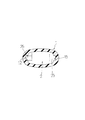
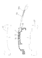
- FIG. 2 The AA cross section part of FIG. 2 is shown. It is an assembly
- the present embodiment forms a handle portion, which has a hollow shape and is integrally formed of a predetermined plastic material.
- the main body 1 and a control device that is provided in the handle main body 1 and controls the opening / closing operation of the door, and an antenna that receives the control device operating radio wave are integrated (hereinafter referred to as this embodiment).
- this embodiment this is referred to as a controller).
- the handle body 1 is formed of a composite material of polycarbonate resin containing glass fiber and polyethylene terephthalate, or a composite material of polycarbonate resin and polybutylene terephthalate. It is what has become.
- the handle body 1 has a hollow integrated shape having openings communicating with both ends thereof, and the shape in the longitudinal direction is formed by a part of an arc having a predetermined curvature. It is what.
- the handle body 1 is provided with a guide portion 12 for holding the controller 2 and having a concave groove shape (see FIGS. 2 and 3). ).
- a guide part 12 has a shape in the longitudinal direction of the same arc shape as the shape of the handle body 1 itself, as shown in FIGS. 3 to 5, for example.
- the guide portion 12 has a concentric shape with respect to the shape of the arc formed by the handle body 1.
- the guide portion 12 provided in the handle main body 1 can be formed integrally with the middle die 55 (see FIG. 5) for forming the internal structure of the handle main body 1, and You will be able to do it at the same time. That is, as shown in FIG. 5, for example, a mold portion 555 for forming the guide portion 12 is integrally provided in a part of the middle die 55 for forming the handle main body 1, and such an intermediate die 55 is formed. By performing the pulling operation along the circumferential direction of the arc forming the handle body 1, the guide portion 12 can be formed simultaneously with the formation of the inside of the handle body 1. Further, a stopper portion 15 is provided at the guide portion 12 having such a configuration, for example, as shown in FIG. 4 or FIG. Then, by engaging the projecting engaging portion 25 formed in a part of the controller 2 at the stopper portion 15, the positioning of the controller 2 in the handle main body 1 is reliably performed. It will be.
- the controller 2 installed in the guide portion 12 has a cubic shape or a strip shape, and has one end side.
- An end portion 29 having a predetermined plane portion is formed in the.
- at least one pair of engaging portions 25 each having a protruding shape is provided at the side surface portion of the strip-shaped controller 2 so as to form a bilaterally symmetric shape in a plan view. (See FIGS. 1 and 2).
- such an engaging portion 25 engages with the groove-shaped guide portion 12 formed in the handle main body 1 so that the entire controller 2 is held in the handle main body 1. It is like that.
- Such a protruding engagement portion 25 is formed with the guide portion 12 and the stopper portion 15 (FIG.
- a cable 23 is provided on the other end side of the controller 2, and a terminal 21 is provided at the tip of the cable 23.
- the power supply to the controller 2 and the transmission of the signal received by the controller 2 to the transmitting / receiving device are performed via the terminal 21 and the cable 23.
- a switch mechanism 6 is provided at the end portion 29 of the controller 2.
- a cap 3 formed so as to close one open end of the handle body 1 is attached to one side surface of the switch mechanism 6.
- the cap 3 is formed in a lid portion 31 formed so as to close the one opening end portion, an attachment leg portion 32 that forms an attachment portion to the handle body 1, and a lower portion of the attachment leg portion 32. And a base portion 33.
- the handle body 1 itself can be reduced in weight while ensuring a certain degree of rigidity.
- the guide portion 12 for mounting the controller 2 and the integrated controller 2 such as an antenna into the handle body 1 can be formed simultaneously with the molding of the hollow handle body 1.
- the controller 2 is inserted into the handle main body 1 formed in this way, and the protruding shape formed in the controller 2 is formed at the groove-shaped guide portion 12 formed in the handle main body 1.
- the longitudinal direction of the guide portion 12 formed in the handle body 1 is formed in the same arc shape as the shape of the handle body 1 itself.
- the guide portion 12 formed in the handle body 1 is formed as shown in FIG.
- the middle mold 55 for forming the internal structure of the handle main body 1 can be made integrally and simultaneously. That is, a mold portion 555 for forming the groove-shaped guide portion 12 is integrally provided on a part of the middle die 55 for molding the handle main body 1, and such an operation for pulling out the middle die 55 is performed.
- the guide portion 12 can be formed simultaneously with the formation of the inside of the handle body by causing the handle body 1 to be formed along the circumferential direction of the arc forming the handle body 1.
- a stopper 15 for holding the controller 2 at a predetermined position in the handle body 1 is provided at the guide portion 12 as shown in FIG. 3 or FIG. 5, for example. ing.
- an engaging portion 25 (see FIGS. 1 and 3) formed in a part of the controller 2 at the stopper portion 15, the positioning of the controller 2 in the handle body 1 is reliably performed. Will come to be.
- the radio wave receiving direction position of the controller 2 is set on the handle body 1.
- An appropriate position can be set with respect to the outer surface, and the reception function of the controller 2 can be maintained in an appropriate state.
- Such a controller 2 basically has a cubic shape, and at least a pair of outer peripheral portions are symmetrical with respect to the longitudinal direction in plan view.
- the engaging portion 25 is provided. Therefore, the mounting operation of the controller 2 in the handle main body 1 is performed through the engaging portion 25. Specifically, first, as shown in FIG. 4A, a terminal 21 provided on one end side of the controller 2 is made to face one opening 19 of the handle body 1. Then, next, for example, as shown in FIGS. 4B and 4C, the engaging portion 25 formed on the outer peripheral portion of the controller 2 is engaged with the guide portion 12 formed in the handle body 1. In the combined state, the controller 2 is sequentially pushed into the handle body 1. As a result, the controller 2 is accommodated in a predetermined position in the handle body 1.
- the engaging portion 25 formed on the side surface portion of the controller 2 is engaged with the stopper portion 15 formed in the handle body 1 as shown in FIGS.
- the controller 2 is reliably positioned in the longitudinal direction in the handle body 1. In this way, the mounting operation of the controller 2 in the handle main body 1 is performed efficiently.
- the controller 2 is housed in a predetermined case in a state where the control device, the antenna, and the like are gathered together, and an end portion 29 formed of a predetermined flat portion on one end side of the case.
- the tip of the mounting leg 32 of the cap 3 for sealing the opening 19 formed on one end surface in the longitudinal direction of the handle main body 1 is formed at such an end 29. It is also conceivable to make them abut.
- the cap 3 is attached to the opening 19 formed on one end surface side of the handle main body 1, whereby the handle of the controller 2 is Attachment to a predetermined position in the main body 1 is surely performed. That is, the positioning of the controller 2 in the handle main body 1 is reliably performed.
- the upper mold 51, the lower mold 52, and the middle mold 55 are set in a predetermined state.
- a predetermined thermoplastic synthetic resin material such as a polycarbonate resin material containing glass fibers
- the mold opening operation (process) of each mold is performed.
- the mold opening process first, the molds are opened by moving the upper and lower molds 51 and 52 in the vertical direction.
- a mold opening (die cutting) operation of the middle mold 55 having an arc shape with respect to the longitudinal direction is performed. As shown in FIG.
- the die-cutting operation of the intermediate die 55 is performed along the circumferential line of the arc formed by the longitudinal center line of the molded product (work) that forms the handle body 1.
- the guide portion 12 and the stopper portion 15 formed in the handle body 1 are formed simultaneously with the formation of the inner diameter side of the handle body 1.
- the drawing operation of the middle die 55 is smoothly performed.
Landscapes
- Fittings On The Vehicle Exterior For Carrying Loads, And Devices For Holding Or Mounting Articles (AREA)
- Lock And Its Accessories (AREA)
Abstract
L'invention vise à former un corps de poignée en matière plastique de sorte qu'il soit creux à l'aide d'un moule, et à adapter un dispositif de commande dans le corps de poignée. A cet effet, l'invention comprend : un corps de poignée (1) ayant une configuration creuse, la totalité du corps de poignée étant formée d'un seul tenant à partir d'une matière plastique prédéterminée ; et un dispositif de commande (2) disposé dans le corps de poignée (1), le dispositif de commande comprenant une antenne, un dispositif de commande pour commander l'ouverture/fermeture ou d'autres actions de la porte, et d'autres éléments qui sont réalisés d'un seul tenant. Le corps de poignée (1) a une configuration d'un seul tenant creuse dans laquelle une ouverture est présente aux deux extrémités, et est formé de sorte que la configuration du corps de poignée dans la direction longitudinale fasse partie d'un arc ayant une courbure prédéterminée. Une section de guidage en forme de rainure (12) pour supporter le dispositif de commande (2) est disposée dans le corps de poignée (1). La section de guidage (12) est réalisée de façon à avoir une configuration en forme d'arc dans la direction longitudinale identique à la forme du corps de poignée (1), ou, autrement dit, une configuration qui est concentrique par rapport à la forme d'arc formée par le corps de poignée (1).
Priority Applications (2)
| Application Number | Priority Date | Filing Date | Title |
|---|---|---|---|
| PCT/JP2011/064354 WO2012176296A1 (fr) | 2011-06-23 | 2011-06-23 | Dispositif de poignée de porte |
| JP2012519810A JP5426767B2 (ja) | 2011-06-23 | 2011-06-23 | ドアハンドル装置 |
Applications Claiming Priority (1)
| Application Number | Priority Date | Filing Date | Title |
|---|---|---|---|
| PCT/JP2011/064354 WO2012176296A1 (fr) | 2011-06-23 | 2011-06-23 | Dispositif de poignée de porte |
Publications (1)
| Publication Number | Publication Date |
|---|---|
| WO2012176296A1 true WO2012176296A1 (fr) | 2012-12-27 |
Family
ID=47422176
Family Applications (1)
| Application Number | Title | Priority Date | Filing Date |
|---|---|---|---|
| PCT/JP2011/064354 Ceased WO2012176296A1 (fr) | 2011-06-23 | 2011-06-23 | Dispositif de poignée de porte |
Country Status (2)
| Country | Link |
|---|---|
| JP (1) | JP5426767B2 (fr) |
| WO (1) | WO2012176296A1 (fr) |
Citations (2)
| Publication number | Priority date | Publication date | Assignee | Title |
|---|---|---|---|---|
| JP2004537664A (ja) * | 2001-08-01 | 2004-12-16 | ヴァレオ エレクトロニク | 自動車用ドアの取手 |
| JP2008057199A (ja) * | 2006-08-31 | 2008-03-13 | Io Industry Co Ltd | 車両用ドアハンドル装置およびその製造方法 |
-
2011
- 2011-06-23 WO PCT/JP2011/064354 patent/WO2012176296A1/fr not_active Ceased
- 2011-06-23 JP JP2012519810A patent/JP5426767B2/ja not_active Expired - Fee Related
Patent Citations (2)
| Publication number | Priority date | Publication date | Assignee | Title |
|---|---|---|---|---|
| JP2004537664A (ja) * | 2001-08-01 | 2004-12-16 | ヴァレオ エレクトロニク | 自動車用ドアの取手 |
| JP2008057199A (ja) * | 2006-08-31 | 2008-03-13 | Io Industry Co Ltd | 車両用ドアハンドル装置およびその製造方法 |
Also Published As
| Publication number | Publication date |
|---|---|
| JPWO2012176296A1 (ja) | 2015-02-23 |
| JP5426767B2 (ja) | 2014-02-26 |
Similar Documents
| Publication | Publication Date | Title |
|---|---|---|
| JP4953014B2 (ja) | 樹脂成形品、樹脂成形品の成形方法、及び成形用金型 | |
| KR101603706B1 (ko) | 라벨이 통합된 성형 제품, 그리고 그 성형 제품을 포함하는 면도기 손잡이 | |
| US9797749B2 (en) | Resolver | |
| EP2441559A3 (fr) | Outil de moulage par injection | |
| US9168688B2 (en) | Injection molding device, injection molding method and housing | |
| EP1810817A3 (fr) | Procédé et appareil de formation de moule, et procédé et appareil de fabrication de lentille plastique | |
| KR101779405B1 (ko) | 블레이드 자동균등 회전용 광섬유 절단기 | |
| WO2017115650A1 (fr) | Procédé de fabrication de corps moulé composite | |
| JP5426767B2 (ja) | ドアハンドル装置 | |
| KR101609375B1 (ko) | 안테나 일체형 케이스 및 그 제조 방법 | |
| CN110193850B (zh) | 刀片组 | |
| JP3163511U (ja) | キャップ付きボトル | |
| FI116101B (fi) | Menetelmä tietoliikennelaitteen antennin sisäisen ja ulkoisen eristysvaipan yhdistämiseksi | |
| US9316280B2 (en) | Spring unit and slide mechanism | |
| US12377588B2 (en) | Rotary injection mold for elastic housing of neckband headset and manufacturing method | |
| JP2015104247A (ja) | 経路維持部材付ワイヤーハーネス及びその製造方法 | |
| KR101423270B1 (ko) | 인서트 몰딩을 이용한 밀폐형 인서트 안테나, 그 제조방법 및 제조금형 | |
| US9056408B2 (en) | Injection molding machine | |
| JP4825068B2 (ja) | モール | |
| JPH0467921A (ja) | 射出成形方法及び装置 | |
| KR101439317B1 (ko) | 가죽 표면을 갖는 휴대폰 케이스 및 그 제조방법 | |
| CN106766609B (zh) | 组装式内胆组件、制冷设备用箱体及制冷设备 | |
| JP5957343B2 (ja) | ハーネスプロテクタ | |
| JP7481919B2 (ja) | アクチュエータ | |
| JP2013016399A (ja) | コネクタ |
Legal Events
| Date | Code | Title | Description |
|---|---|---|---|
| ENP | Entry into the national phase |
Ref document number: 2012519810 Country of ref document: JP Kind code of ref document: A |
|
| 121 | Ep: the epo has been informed by wipo that ep was designated in this application |
Ref document number: 11868265 Country of ref document: EP Kind code of ref document: A1 |
|
| NENP | Non-entry into the national phase |
Ref country code: DE |
|
| 122 | Ep: pct application non-entry in european phase |
Ref document number: 11868265 Country of ref document: EP Kind code of ref document: A1 |