WO2012176320A1 - ティビアパッド及びティビアパッド設置構造 - Google Patents
ティビアパッド及びティビアパッド設置構造 Download PDFInfo
- Publication number
- WO2012176320A1 WO2012176320A1 PCT/JP2011/064479 JP2011064479W WO2012176320A1 WO 2012176320 A1 WO2012176320 A1 WO 2012176320A1 JP 2011064479 W JP2011064479 W JP 2011064479W WO 2012176320 A1 WO2012176320 A1 WO 2012176320A1
- Authority
- WO
- WIPO (PCT)
- Prior art keywords
- vehicle
- tibia pad
- rib
- respect
- right foot
- Prior art date
- Legal status (The legal status is an assumption and is not a legal conclusion. Google has not performed a legal analysis and makes no representation as to the accuracy of the status listed.)
- Ceased
Links
Images




Classifications
-
- B—PERFORMING OPERATIONS; TRANSPORTING
- B60—VEHICLES IN GENERAL
- B60R—VEHICLES, VEHICLE FITTINGS, OR VEHICLE PARTS, NOT OTHERWISE PROVIDED FOR
- B60R21/00—Arrangements or fittings on vehicles for protecting or preventing injuries to occupants or pedestrians in case of accidents or other traffic risks
- B60R21/02—Occupant safety arrangements or fittings, e.g. crash pads
- B60R21/04—Padded linings for the vehicle interior ; Energy absorbing structures associated with padded or non-padded linings
-
- B—PERFORMING OPERATIONS; TRANSPORTING
- B60—VEHICLES IN GENERAL
- B60R—VEHICLES, VEHICLE FITTINGS, OR VEHICLE PARTS, NOT OTHERWISE PROVIDED FOR
- B60R21/00—Arrangements or fittings on vehicles for protecting or preventing injuries to occupants or pedestrians in case of accidents or other traffic risks
- B60R2021/003—Arrangements or fittings on vehicles for protecting or preventing injuries to occupants or pedestrians in case of accidents or other traffic risks characterised by occupant or pedestian
- B60R2021/0039—Body parts of the occupant or pedestrian affected by the accident
- B60R2021/0046—Feet
Definitions
- the tibia pad according to the first aspect of the present invention is placed below and behind the accelerator pedal provided in the vehicle and on which the heel of the right foot of the occupant who is stepping on the accelerator pedal is placed.
- a right foot mounting portion having a rear portion and a front portion integrally formed on the front side of the rear portion of the vehicle and positioned below the accelerator pedal; and at least a bottom surface of the rear portion of the right foot mounting portion along the vehicle front-rear direction. It is formed by a portion between a pair of grooves formed side by side in the vehicle width direction, and at a position shifted to one side in the vehicle width direction with respect to a center line passing through the vehicle width direction center portion of the accelerator pedal. And a provided rib.
- the right foot placement portion when a load is applied to the rear portion of the right foot placement portion by the heel of the occupant due to the frontal collision of the vehicle, the right foot placement portion is opposite to the side where the rib is provided, that is, in the vehicle width direction. Since it tilts to the other side, the ankle of the right foot of the occupant can be rotated to the other side in the vehicle width direction. Thereby, the axial load generated on the right lower leg of the occupant, the lateral rotation moment of the heel, and the longitudinal moment of the heel can be effectively distributed. As a result, the peak value of the tibia index can be further reduced for the occupant's right foot.
- the tibia pad according to the second aspect of the present invention is the tibia pad according to the first aspect, wherein the right foot placement portion is directed to the upper side of the vehicle as it goes toward the front side of the vehicle and the horizontal portion as the rear portion formed horizontally.
- An inclined portion as the front portion that is inclined with respect to the vehicle longitudinal direction, and the rib is formed on the horizontal portion, the inclined portion, and the rear side.
- the protrusion height is lower than that of the rib, and the front rib has a step portion between the rib and the rear rib.
- the right foot mounting portion bends around the vehicle width direction axis starting from this stepped portion. Therefore, since the slip of the heel toward the vehicle front side can be suppressed, the load on the right lower leg of the occupant can be applied to the horizontal portion, which is the target position, immediately after the collision.
- the front portion of the right foot placement portion is an inclined portion that is inclined with respect to the vehicle front-rear direction so as to be directed toward the vehicle upper side toward the vehicle front side.
- a weak body portion is formed as a through-hole penetrating through or a groove opened in one of the upper surface and the bottom surface thereof.
- the right foot placement portion bends around the axis in the vehicle width direction starting from this weak body portion. Therefore, since the slip of the heel toward the vehicle front side can be suppressed, the load on the right lower leg of the occupant can be applied to the horizontal portion, which is the target position, immediately after the collision.
- the tibia pad according to a fourth aspect of the present invention is the tibia pad according to the third aspect, wherein the weak body portion is shifted to the other side in the vehicle width direction and the rear side of the vehicle with respect to the first weak body portion and the first weak body portion. And a second weak body portion formed at the same position.
- a tibia pad according to a fifth aspect of the present invention is the tibia pad according to any one of the first aspect to the fourth aspect, provided on the left side of the vehicle with respect to the right foot placement portion, on which the left foot of the occupant is placed.
- a mounting portion is provided, and the left foot mounting portion is formed with a through hole penetrating in the thickness direction or a cut-off portion formed as a groove opened on one of the upper surface and the bottom surface.
- the connecting portion is formed with a through-hole penetrating in the thickness direction or a space portion formed as a groove opened on one of the upper surface and the bottom surface.
- a sound absorbing material is provided in at least the space portion among the pair of groove portions formed in the right foot placement portion, the shaving portion formed in the left foot placement portion, and the space portion formed in the connection portion. It has been. Therefore, it is possible to absorb the noise such as road noise and engine sound entering the vehicle interior via the vehicle body panel, the tire house, and the like with this sound absorbing material.
- a tibia pad according to a seventh aspect of the present invention is the tibia pad according to any one of the first aspect to the sixth aspect, provided on the left side of the vehicle with respect to the right foot placement portion, and is formed horizontally so that the left foot of the occupant A left foot having a left horizontal portion on which a heel is placed, and a left inclined portion that is integrally formed on the vehicle front side of the left horizontal portion and is inclined with respect to the vehicle front-rear direction so as to go to the vehicle upper side toward the vehicle front side Folding start point provided with a mounting portion and formed as a through-hole penetrating in the thickness direction or a groove opened in one of the upper surface and the bottom surface at the transition portion between the left horizontal portion and the left inclined portion It is set as the structure in which the part was formed.
- the left foot mounting part has a left horizontal part and a left inclined part, and a through-hole penetrating in the thickness direction is formed at a transition part between the left horizontal part and the left inclined part.
- a bending starting point portion formed as a groove opened on one of the upper surface and the bottom surface is formed. Accordingly, when a load is applied to the left horizontal portion due to the heel of the left foot of the occupant due to the frontal collision of the vehicle, the left foot placement portion is bent around the axis in the vehicle width direction starting from this bending start portion. As a result, slippage of the heel toward the front of the vehicle can be suppressed, so that the load on the left lower leg of the occupant can be applied to the left horizontal portion, which is the target position, immediately after the collision.
- the tibia pad installation structure includes a horizontal portion as the rear portion formed horizontally and a vehicle front-rear direction so that the vehicle heads upward toward the vehicle front side.
- the tibia pad according to any one of the first aspect to the seventh aspect including the right foot placing portion having the inclined portion as the front portion inclined with respect to the front portion, and the tibia pad is placed,
- a vehicle body panel having a curved portion that has an apex on a center line passing through a center portion in the vehicle width direction of the accelerator pedal and that protrudes downward from the vehicle is provided at a position located below the horizontal portion.
- the vehicle body panel has a curved portion that has a vertex on the center line passing through the center portion in the vehicle width direction of the accelerator pedal and has a convex portion on the lower side of the vehicle at a portion located below the horizontal portion. Is formed. Therefore, a large compression deformation stroke of the horizontal portion can be secured on the center line passing through the center portion of the accelerator pedal in the vehicle width direction, so that the shock absorbing performance in the horizontal portion can be further enhanced. Thereby, the peak value of the tibia index can be further reduced for the right foot of the occupant.
- the tibia pad according to the ninth aspect of the present invention is the tibia pad installation structure according to the eighth aspect, wherein the vehicle body panel is formed with a wall portion facing the vehicle upper side on the vehicle right side with respect to the accelerator pedal, and the rib is It is the structure provided in the position which shifted
- the rib is provided at a position shifted to the right side of the vehicle with respect to the center line passing through the center of the accelerator pedal in the vehicle width direction. Therefore, when a load is applied to the rear portion of the right foot placement portion by the heel of the occupant's right foot due to the frontal collision of the vehicle, the ankle of the occupant's right foot can be rotated to the left side of the vehicle, which is opposite to the wall portion. it can. Thereby, interference with a passenger
- the peak value of the tibia index can be further reduced.
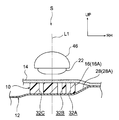
- FIG. 2 is an enlarged cross-sectional view of an essential part taken along line 2-2 in FIG.
- FIG. 3 is an enlarged cross-sectional view taken along the line 3-3 in FIG.
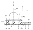
- FIG. 4 is an enlarged cross-sectional view taken along line 4-4 of FIG.
- FIG. 5 is an enlarged cross-sectional view taken along line 5-5 in FIG.
- FIG. 6 is an enlarged sectional view taken along line 6-6 in FIG.
- FIG. 7 is a diagram showing a state in which a load acts on the right horizontal portion shown in FIG. 6 and the right foot placement portion is bent around an axis in the vehicle width direction.
- the arrow UP, the arrow FR, and the arrow RH shown in each figure respectively indicate the vehicle upper side, the vehicle front side, and the vehicle right side.
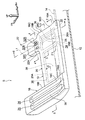
- a tibia pad installation structure S according to an embodiment of the present invention shown in FIG. 1 is applied to a foot portion of a driver seat of a left-hand drive vehicle as an example.
- the tibia pad installation structure S includes a tibia pad 10.
- the tibia pad 10 is placed on a vehicle body panel 12 which is a dash panel, for example.
- An interior material 14 such as a carpet or a mat is laid on the body panel 12, and the tibia pad 10 is interposed between the body panel 12 and the interior material 14.
- the tibia pad 10 is made of, for example, foam resin having shock absorption, and includes a right foot placement portion 16, a left foot placement portion 18, and a connecting portion 20.
- the right inclined portion 16B is formed with a plurality of weak body portions 32A to 32C which are through holes penetrating in the thickness direction (see also FIG. 4).
- the plurality of weak body portions 32A to 32C are formed on the vehicle front side with respect to the pair of groove portions 24 described above, and are positioned below the rear end portion 22A of the accelerator pedal 22 (see also FIG. 6).
- the right foot placement portion 16 is opposite to the side where the rib 26 is provided, that is, on the left side of the vehicle. Since it tilts, the ankle of the right foot of the occupant can be rotated to the left side of the vehicle.
- the axial load Fz generated on the right lower leg 52 of the occupant, the lateral rotation moment Mx of the heel 54, and the rotational moment My in the front-rear direction of the heel 50 are effectively distributed. can do.
- the peak value of the tibia index can be further reduced for the occupant's right foot.
- the vehicle body panel 12 has an apex on a center line L1 passing through the center in the vehicle width direction of the accelerator pedal 22 (see FIG. 1) at a portion located below the right horizontal portion 16A.
- a curved portion 30 having 30A and projecting downward is formed. Therefore, a large compression deformation stroke of the right horizontal portion 16A can be secured on the center line L1 passing through the center portion of the accelerator pedal 22 in the vehicle width direction, so that the shock absorbing performance in the right horizontal portion 16A can be further enhanced. . Thereby, the peak value of the tibia index can be further reduced for the right foot of the occupant.
- the connecting portion 20 is formed with a space portion 36 which is a groove opened to the bottom surface 20 ⁇ / b> A.
- the space portion 36 is provided with a sound absorbing material 38 such as a felt material. Therefore, noise such as road noise and engine noise that enters the vehicle interior via the vehicle body panel 12 and the tire house can be absorbed by the sound absorbing material 38.
- the sound absorbing material 38 is provided only in the space portion 36, in addition, it is provided in at least one of the above-described pair of groove portions 24, the plurality of weak body portions 32A to 32C, and the meat scraping portion 34. May be.
- the tibia pad installation structure S was applied to the left-hand drive vehicle, it may be applied to the right-hand drive vehicle.
- the wall portion formed on the right side of the feet of the driver seat corresponds to the wall portion facing the vehicle upper side in the present invention.
Landscapes
- Engineering & Computer Science (AREA)
- Mechanical Engineering (AREA)
- Passenger Equipment (AREA)
Abstract
Description
S ティビアパッド設置構造
10 ティビアパッド
12 車体パネル
14 内装材
16 右足載置部
16A 右側水平部(右足載置部の後部、水平部)
16B 右側傾斜部(右足載置部の前部、傾斜部)
16C 底面
18 左足載置部
18A 左側水平部
18B 左側傾斜部
18C 移行部
20 連結部
22 アクセルペダル
24 溝部
26 リブ
26A 後側リブ
26B 前側リブ
26C 段差部
28A トンネル部の左側部(壁部)
30 湾曲部
30A 頂点
32A,32B 第一弱体部(弱体部の一部)
32C 第二弱体部(弱体部の一部)
34 肉削ぎ部
36 空間部
38 吸音材
40 折曲起点部
Claims (9)
- 車両に設けられたアクセルペダルの下方且つ後方に位置し前記アクセルペダルを踏んでいる乗員の右足の踵が載置される後部と、前記後部の車両前側に一体に形成され前記アクセルペダルの下方に位置する前部と、を有する右足載置部と、
前記右足載置部における少なくとも前記後部の底面に車両前後方向に沿って延び車両幅方向に並んで形成された一対の溝部の間の部位によって形成されると共に、前記アクセルペダルの車両幅方向中央部を通る中心線に対して車両幅方向一方側にずれた位置に設けられたリブと、
を備えたティビアパッド。 - 前記右足載置部は、水平に形成された前記後部としての水平部と、車両前側に向かうに従って車両上側に向かうように車両前後方向に対して傾斜する前記前部としての傾斜部と、を有し、
前記リブは、前記水平部に形成された後側リブと、前記傾斜部に形成されると共に、前記後側リブよりも突出高さが低くされ、前記後側リブとの間に段差部を有する前側リブと、を有している、
請求項1に記載のティビアパッド。 - 前記右足載置部は、水平に形成された前記後部としての水平部と、車両前側に向かうに従って車両上側に向かうように車両前後方向に対して傾斜する前記前部としての傾斜部と、を有し、
前記傾斜部には、その厚み方向に貫通する貫通孔、又は、その上面及び底面の一方に開口する溝とされた弱体部が形成されている、
請求項1又は請求項2に記載のティビアパッド。 - 前記弱体部は、第一弱体部と、前記第一弱体部に対して車両幅方向他方側且つ車両後側にずれた位置に形成された第二弱体部と、を有している、
請求項3に記載のティビアパッド。 - 前記右足載置部に対する車両左側に設けられ、乗員の左足が載置される左足載置部を備え、
前記左足載置部には、その厚み方向に貫通する貫通孔、又は、その上面及び底面の一方に開口する溝とされた肉削ぎ部が形成されている、
請求項1~請求項4のいずれか一項に記載のティビアパッド。 - 前記右足載置部と前記左足載置部とを車両幅方向に連結する連結部を備え、
前記連結部には、その厚み方向に貫通する貫通孔、又は、その上面及び底面の一方に開口する溝とされた空間部が形成され、
前記一対の溝部、前記肉削ぎ部、及び、前記空間部のうち少なくとも前記空間部には、吸音材が設けられている、
請求項5に記載のティビアパッド。 - 前記右足載置部に対する車両左側に設けられ、水平に形成され前記乗員の左足の踵が載置される左側水平部と、前記左側水平部の車両前側に一体に形成され車両前側に向かうに従って車両上側に向かうように車両前後方向に対して傾斜する左側傾斜部と、を有する左足載置部を備え、
前記左側水平部と前記左側傾斜部との間の移行部には、その厚み方向に貫通する貫通孔、又は、その上面及び底面の一方に開口する溝とされた折曲起点部が形成されている、
請求項1~請求項6のいずれか一項に記載のティビアパッド。 - 水平に形成された前記後部としての水平部と、車両前側に向かうに従って車両上側に向かうように車両前後方向に対して傾斜する前記前部としての傾斜部と、を有する前記右足載置部を備えた請求項1~請求項7のいずれか一項に記載のティビアパッドと、
前記ティビアパッドが載置され、前記水平部の下方に位置する部位に、前記アクセルペダルの車両幅方向中央部を通る中心線上に頂点を有し車両下側に凸を成す湾曲部が形成された車体パネルと、
を備えたティビアパッド設置構造。 - 前記車体パネルには、前記アクセルペダルに対する車両右側に、車両上側に向う壁部が形成され、
前記リブは、前記中心線に対して車両右側にずれた位置に設けられている、
請求項8に記載のティビアパッド設置構造。
Priority Applications (5)
| Application Number | Priority Date | Filing Date | Title |
|---|---|---|---|
| US14/125,680 US9022451B2 (en) | 2011-06-23 | 2011-06-23 | Tibia pad and tibia pad installation structure |
| CN201180071763.XA CN103619656B (zh) | 2011-06-23 | 2011-06-23 | 胫部衬垫以及胫部衬垫设置结构 |
| JP2013521390A JP5590238B2 (ja) | 2011-06-23 | 2011-06-23 | ティビアパッド及びティビアパッド設置構造 |
| EP11868281.4A EP2724898B1 (en) | 2011-06-23 | 2011-06-23 | Tibia pad and tibia pad installation structure |
| PCT/JP2011/064479 WO2012176320A1 (ja) | 2011-06-23 | 2011-06-23 | ティビアパッド及びティビアパッド設置構造 |
Applications Claiming Priority (1)
| Application Number | Priority Date | Filing Date | Title |
|---|---|---|---|
| PCT/JP2011/064479 WO2012176320A1 (ja) | 2011-06-23 | 2011-06-23 | ティビアパッド及びティビアパッド設置構造 |
Publications (1)
| Publication Number | Publication Date |
|---|---|
| WO2012176320A1 true WO2012176320A1 (ja) | 2012-12-27 |
Family
ID=47422195
Family Applications (1)
| Application Number | Title | Priority Date | Filing Date |
|---|---|---|---|
| PCT/JP2011/064479 Ceased WO2012176320A1 (ja) | 2011-06-23 | 2011-06-23 | ティビアパッド及びティビアパッド設置構造 |
Country Status (5)
| Country | Link |
|---|---|
| US (1) | US9022451B2 (ja) |
| EP (1) | EP2724898B1 (ja) |
| JP (1) | JP5590238B2 (ja) |
| CN (1) | CN103619656B (ja) |
| WO (1) | WO2012176320A1 (ja) |
Cited By (4)
| Publication number | Priority date | Publication date | Assignee | Title |
|---|---|---|---|---|
| WO2014174685A1 (ja) * | 2013-04-26 | 2014-10-30 | トヨタ自動車株式会社 | 右足保護構造 |
| JP2016104595A (ja) * | 2014-12-01 | 2016-06-09 | スズキ株式会社 | 車両用フットレスト構造 |
| JP2021011171A (ja) * | 2019-07-05 | 2021-02-04 | 本田技研工業株式会社 | 車両のフットレスト支持部構造 |
| FR3136200A1 (fr) * | 2022-06-07 | 2023-12-08 | Psa Automobiles Sa | Structure de véhicule automobile |
Families Citing this family (7)
| Publication number | Priority date | Publication date | Assignee | Title |
|---|---|---|---|---|
| FR2981310B1 (fr) * | 2011-10-17 | 2013-10-25 | Renault Sa | Repose-pied pour vehicule |
| US9045059B1 (en) * | 2014-02-19 | 2015-06-02 | Ford Global Technologies, Llc | Driver's plastic footrest assembly |
| US9216678B1 (en) * | 2014-06-27 | 2015-12-22 | Tyanne Mobley | Heel protecting vehicle floor mat device |
| WO2016092585A1 (ja) * | 2014-12-08 | 2016-06-16 | ボルボトラックコーポレーション | 高さ調整機能付きスライド式ヒールパッド |
| US9718417B2 (en) * | 2015-08-28 | 2017-08-01 | Toyota Motor Engineering & Manufacturing North America, Inc. | Vehicle floor |
| US10889226B1 (en) * | 2019-10-14 | 2021-01-12 | Ford Global Technologies, Llc | Vehicle pedal cover |
| JP7414793B2 (ja) * | 2021-12-17 | 2024-01-16 | 本田技研工業株式会社 | 車両用フロアカーペット |
Citations (13)
| Publication number | Priority date | Publication date | Assignee | Title |
|---|---|---|---|---|
| JPH0986255A (ja) * | 1995-09-25 | 1997-03-31 | Toyota Motor Corp | 車両用フットレスト |
| JPH10297343A (ja) * | 1997-04-25 | 1998-11-10 | Honda Motor Co Ltd | 自動車用フットレスト |
| JPH10297345A (ja) * | 1997-04-28 | 1998-11-10 | Honda Motor Co Ltd | 自動車用フットレスト |
| JP2004306791A (ja) | 2003-04-07 | 2004-11-04 | Sekisui Plastics Co Ltd | 車両用下肢部衝撃吸収パッド |
| JP2005081958A (ja) | 2003-09-08 | 2005-03-31 | Toyota Motor Corp | 下肢保護構造 |
| JP2005280560A (ja) * | 2004-03-30 | 2005-10-13 | Sekisui Plastics Co Ltd | 防音性を付与した車両用下肢部衝撃吸収パッド |
| JP2005324563A (ja) | 2004-05-12 | 2005-11-24 | Hayashi Engineering Inc | ティビアパッド |
| JP2007083902A (ja) * | 2005-09-22 | 2007-04-05 | Sekisui Plastics Co Ltd | 車両用下肢部衝撃吸収パッド |
| JP2007098978A (ja) * | 2005-09-30 | 2007-04-19 | Sekisui Plastics Co Ltd | 車両用フロアスペーサ |
| JP2007290603A (ja) | 2006-04-26 | 2007-11-08 | Sekisui Plastics Co Ltd | 下肢部衝撃吸収パッドおよび車両用フロアスペーサ |
| JP2008511499A (ja) | 2004-09-03 | 2008-04-17 | ルノー・エス・アー・エス | 自動車の搭乗者の足のための衝撃吸収部品 |
| JP2008100685A (ja) | 2008-01-15 | 2008-05-01 | Sekisui Plastics Co Ltd | 車両用下肢部衝撃吸収パッドを備えた車両構造 |
| JP2008110758A (ja) * | 2008-01-15 | 2008-05-15 | Sekisui Plastics Co Ltd | 車両用下肢部衝撃吸収パッド |
Family Cites Families (8)
| Publication number | Priority date | Publication date | Assignee | Title |
|---|---|---|---|---|
| US6224133B1 (en) * | 1998-11-04 | 2001-05-01 | Ford Global Technologies, Inc. | Secondary floor assembly |
| ITTO20020678A1 (it) | 2001-08-07 | 2004-01-29 | Honda Motor Co Ltd | Ammortizzatore per un veicolo a due ruote |
| JP4130558B2 (ja) | 2001-08-07 | 2008-08-06 | 株式会社イノアックコーポレーション | 二輪車用衝撃吸収体 |
| JP4207592B2 (ja) * | 2003-02-13 | 2009-01-14 | 三菱自動車工業株式会社 | 車両のフロア構造 |
| US20070080562A1 (en) | 2003-11-19 | 2007-04-12 | Hayashi Engineering Inc. | Impact absorbing body |
| CN2726969Y (zh) * | 2004-09-10 | 2005-09-21 | 李宋杰 | 汽车踏板衬垫 |
| EP1816056B1 (en) * | 2006-02-02 | 2016-11-02 | Mazda Motor Corporation | Automobile movable floor apparatus |
| US8857895B2 (en) * | 2011-06-17 | 2014-10-14 | David J. Millar | Tibia force reduction wedge |
-
2011
- 2011-06-23 JP JP2013521390A patent/JP5590238B2/ja active Active
- 2011-06-23 US US14/125,680 patent/US9022451B2/en active Active
- 2011-06-23 CN CN201180071763.XA patent/CN103619656B/zh active Active
- 2011-06-23 EP EP11868281.4A patent/EP2724898B1/en active Active
- 2011-06-23 WO PCT/JP2011/064479 patent/WO2012176320A1/ja not_active Ceased
Patent Citations (13)
| Publication number | Priority date | Publication date | Assignee | Title |
|---|---|---|---|---|
| JPH0986255A (ja) * | 1995-09-25 | 1997-03-31 | Toyota Motor Corp | 車両用フットレスト |
| JPH10297343A (ja) * | 1997-04-25 | 1998-11-10 | Honda Motor Co Ltd | 自動車用フットレスト |
| JPH10297345A (ja) * | 1997-04-28 | 1998-11-10 | Honda Motor Co Ltd | 自動車用フットレスト |
| JP2004306791A (ja) | 2003-04-07 | 2004-11-04 | Sekisui Plastics Co Ltd | 車両用下肢部衝撃吸収パッド |
| JP2005081958A (ja) | 2003-09-08 | 2005-03-31 | Toyota Motor Corp | 下肢保護構造 |
| JP2005280560A (ja) * | 2004-03-30 | 2005-10-13 | Sekisui Plastics Co Ltd | 防音性を付与した車両用下肢部衝撃吸収パッド |
| JP2005324563A (ja) | 2004-05-12 | 2005-11-24 | Hayashi Engineering Inc | ティビアパッド |
| JP2008511499A (ja) | 2004-09-03 | 2008-04-17 | ルノー・エス・アー・エス | 自動車の搭乗者の足のための衝撃吸収部品 |
| JP2007083902A (ja) * | 2005-09-22 | 2007-04-05 | Sekisui Plastics Co Ltd | 車両用下肢部衝撃吸収パッド |
| JP2007098978A (ja) * | 2005-09-30 | 2007-04-19 | Sekisui Plastics Co Ltd | 車両用フロアスペーサ |
| JP2007290603A (ja) | 2006-04-26 | 2007-11-08 | Sekisui Plastics Co Ltd | 下肢部衝撃吸収パッドおよび車両用フロアスペーサ |
| JP2008100685A (ja) | 2008-01-15 | 2008-05-01 | Sekisui Plastics Co Ltd | 車両用下肢部衝撃吸収パッドを備えた車両構造 |
| JP2008110758A (ja) * | 2008-01-15 | 2008-05-15 | Sekisui Plastics Co Ltd | 車両用下肢部衝撃吸収パッド |
Non-Patent Citations (1)
| Title |
|---|
| See also references of EP2724898A4 * |
Cited By (10)
| Publication number | Priority date | Publication date | Assignee | Title |
|---|---|---|---|---|
| WO2014174685A1 (ja) * | 2013-04-26 | 2014-10-30 | トヨタ自動車株式会社 | 右足保護構造 |
| CN104684765A (zh) * | 2013-04-26 | 2015-06-03 | 丰田自动车株式会社 | 右脚保护结构 |
| JP5804212B2 (ja) * | 2013-04-26 | 2015-11-04 | トヨタ自動車株式会社 | 右足保護構造 |
| CN104684765B (zh) * | 2013-04-26 | 2016-11-09 | 丰田自动车株式会社 | 右脚保护结构 |
| US9539973B2 (en) | 2013-04-26 | 2017-01-10 | Toyota Jidosha Kabushiki Kaisha | Right foot protecting structure |
| JP2016104595A (ja) * | 2014-12-01 | 2016-06-09 | スズキ株式会社 | 車両用フットレスト構造 |
| JP2021011171A (ja) * | 2019-07-05 | 2021-02-04 | 本田技研工業株式会社 | 車両のフットレスト支持部構造 |
| JP7104666B2 (ja) | 2019-07-05 | 2022-07-21 | 本田技研工業株式会社 | 車両のフットレスト支持部構造 |
| US11679708B2 (en) | 2019-07-05 | 2023-06-20 | Honda Motor Co., Ltd. | Vehicle footrest support structure |
| FR3136200A1 (fr) * | 2022-06-07 | 2023-12-08 | Psa Automobiles Sa | Structure de véhicule automobile |
Also Published As
| Publication number | Publication date |
|---|---|
| US20140103680A1 (en) | 2014-04-17 |
| JP5590238B2 (ja) | 2014-09-17 |
| EP2724898A4 (en) | 2015-04-22 |
| EP2724898A1 (en) | 2014-04-30 |
| US9022451B2 (en) | 2015-05-05 |
| CN103619656A (zh) | 2014-03-05 |
| CN103619656B (zh) | 2016-03-30 |
| JPWO2012176320A1 (ja) | 2015-02-23 |
| EP2724898B1 (en) | 2017-05-31 |
Similar Documents
| Publication | Publication Date | Title |
|---|---|---|
| JP5590238B2 (ja) | ティビアパッド及びティビアパッド設置構造 | |
| JP5590239B2 (ja) | ティビアパッド及びティビアパッド設置構造 | |
| JP6368851B2 (ja) | 車体構造 | |
| TW200422220A (en) | Floor structure of vehicle | |
| JP5928869B2 (ja) | 車体前部におけるダッシュクロスメンバの取付構造 | |
| JP2003191862A (ja) | 車体前部構造 | |
| RU2545553C2 (ru) | Задний пол автотранспортного средства и транспортное средство, оборудованное таким полом | |
| JP2012153185A (ja) | 車両用フロア構造 | |
| WO2014174685A1 (ja) | 右足保護構造 | |
| JP5687478B2 (ja) | 自動車のフロア構造 | |
| JP2014177191A (ja) | インストルメントパネル | |
| JP2000516881A (ja) | リブ一体型防音層 | |
| JP4087824B2 (ja) | ニーボルスター | |
| JP4960226B2 (ja) | 自動車の床の被覆装置 | |
| JP2001219872A (ja) | 車両用フロア構造 | |
| JP2000095150A (ja) | 車両用ペダル下方のフロア構造 | |
| JP2003127909A (ja) | 自動車の車体前部構造 | |
| JP2007223558A (ja) | 車両用フットレスト構造 | |
| JP3969041B2 (ja) | 自動車のフロア構造 | |
| JP6543106B2 (ja) | 吸音材 | |
| JP2008126698A (ja) | 車両ルーフ部の騒音低減構造 | |
| JP2007131180A (ja) | ペダル構造 | |
| JPH05645A (ja) | 車両用バンパ構造 | |
| JP5776341B2 (ja) | 車両用フロアカーペット | |
| JP2013010439A (ja) | 車両用フットレスト |
Legal Events
| Date | Code | Title | Description |
|---|---|---|---|
| WWE | Wipo information: entry into national phase |
Ref document number: 201180071763.X Country of ref document: CN |
|
| 121 | Ep: the epo has been informed by wipo that ep was designated in this application |
Ref document number: 11868281 Country of ref document: EP Kind code of ref document: A1 |
|
| DPE1 | Request for preliminary examination filed after expiration of 19th month from priority date (pct application filed from 20040101) | ||
| ENP | Entry into the national phase |
Ref document number: 2013521390 Country of ref document: JP Kind code of ref document: A |
|
| WWE | Wipo information: entry into national phase |
Ref document number: 14125680 Country of ref document: US |
|
| REEP | Request for entry into the european phase |
Ref document number: 2011868281 Country of ref document: EP |
|
| WWE | Wipo information: entry into national phase |
Ref document number: 2011868281 Country of ref document: EP |
|
| NENP | Non-entry into the national phase |
Ref country code: DE |