WO2012176336A1 - Élément chauffant à plaques et dispositif de cycle de réfrigération - Google Patents
Élément chauffant à plaques et dispositif de cycle de réfrigération Download PDFInfo
- Publication number
- WO2012176336A1 WO2012176336A1 PCT/JP2011/064580 JP2011064580W WO2012176336A1 WO 2012176336 A1 WO2012176336 A1 WO 2012176336A1 JP 2011064580 W JP2011064580 W JP 2011064580W WO 2012176336 A1 WO2012176336 A1 WO 2012176336A1
- Authority
- WO
- WIPO (PCT)
- Prior art keywords
- fluid
- main pipe
- heat exchanger
- flow path
- plate
- Prior art date
- Legal status (The legal status is an assumption and is not a legal conclusion. Google has not performed a legal analysis and makes no representation as to the accuracy of the status listed.)
- Ceased
Links
Images


Classifications
-
- F—MECHANICAL ENGINEERING; LIGHTING; HEATING; WEAPONS; BLASTING
- F28—HEAT EXCHANGE IN GENERAL
- F28F—DETAILS OF HEAT-EXCHANGE AND HEAT-TRANSFER APPARATUS, OF GENERAL APPLICATION
- F28F3/00—Plate-like or laminated elements; Assemblies of plate-like or laminated elements
- F28F3/08—Elements constructed for building-up into stacks, e.g. capable of being taken apart for cleaning
-
- F—MECHANICAL ENGINEERING; LIGHTING; HEATING; WEAPONS; BLASTING
- F28—HEAT EXCHANGE IN GENERAL
- F28F—DETAILS OF HEAT-EXCHANGE AND HEAT-TRANSFER APPARATUS, OF GENERAL APPLICATION
- F28F9/00—Casings; Header boxes; Auxiliary supports for elements; Auxiliary members within casings
- F28F9/02—Header boxes; End plates
- F28F9/026—Header boxes; End plates with static flow control means, e.g. with means for uniformly distributing heat exchange media into conduits
- F28F9/027—Header boxes; End plates with static flow control means, e.g. with means for uniformly distributing heat exchange media into conduits in the form of distribution pipes
- F28F9/0273—Header boxes; End plates with static flow control means, e.g. with means for uniformly distributing heat exchange media into conduits in the form of distribution pipes with multiple holes
-
- F—MECHANICAL ENGINEERING; LIGHTING; HEATING; WEAPONS; BLASTING
- F28—HEAT EXCHANGE IN GENERAL
- F28D—HEAT-EXCHANGE APPARATUS, NOT PROVIDED FOR IN ANOTHER SUBCLASS, IN WHICH THE HEAT-EXCHANGE MEDIA DO NOT COME INTO DIRECT CONTACT
- F28D9/00—Heat-exchange apparatus having stationary plate-like or laminated conduit assemblies for both heat-exchange media, the media being in contact with different sides of a conduit wall
- F28D9/0031—Heat-exchange apparatus having stationary plate-like or laminated conduit assemblies for both heat-exchange media, the media being in contact with different sides of a conduit wall the conduits for one heat-exchange medium being formed by paired plates touching each other
- F28D9/0043—Heat-exchange apparatus having stationary plate-like or laminated conduit assemblies for both heat-exchange media, the media being in contact with different sides of a conduit wall the conduits for one heat-exchange medium being formed by paired plates touching each other the plates having openings therein for circulation of at least one heat-exchange medium from one conduit to another
- F28D9/005—Heat-exchange apparatus having stationary plate-like or laminated conduit assemblies for both heat-exchange media, the media being in contact with different sides of a conduit wall the conduits for one heat-exchange medium being formed by paired plates touching each other the plates having openings therein for circulation of at least one heat-exchange medium from one conduit to another the plates having openings therein for both heat-exchange media
-
- F—MECHANICAL ENGINEERING; LIGHTING; HEATING; WEAPONS; BLASTING
- F28—HEAT EXCHANGE IN GENERAL
- F28F—DETAILS OF HEAT-EXCHANGE AND HEAT-TRANSFER APPARATUS, OF GENERAL APPLICATION
- F28F13/00—Arrangements for modifying heat-transfer, e.g. increasing, decreasing
- F28F13/06—Arrangements for modifying heat-transfer, e.g. increasing, decreasing by affecting the pattern of flow of the heat-exchange media
-
- F—MECHANICAL ENGINEERING; LIGHTING; HEATING; WEAPONS; BLASTING
- F28—HEAT EXCHANGE IN GENERAL
- F28D—HEAT-EXCHANGE APPARATUS, NOT PROVIDED FOR IN ANOTHER SUBCLASS, IN WHICH THE HEAT-EXCHANGE MEDIA DO NOT COME INTO DIRECT CONTACT
- F28D21/00—Heat-exchange apparatus not covered by any of the groups F28D1/00 - F28D20/00
- F28D2021/0019—Other heat exchangers for particular applications; Heat exchange systems not otherwise provided for
- F28D2021/0068—Other heat exchangers for particular applications; Heat exchange systems not otherwise provided for for refrigerant cycles
- F28D2021/007—Condensers
-
- F—MECHANICAL ENGINEERING; LIGHTING; HEATING; WEAPONS; BLASTING
- F28—HEAT EXCHANGE IN GENERAL
- F28D—HEAT-EXCHANGE APPARATUS, NOT PROVIDED FOR IN ANOTHER SUBCLASS, IN WHICH THE HEAT-EXCHANGE MEDIA DO NOT COME INTO DIRECT CONTACT
- F28D21/00—Heat-exchange apparatus not covered by any of the groups F28D1/00 - F28D20/00
- F28D2021/0019—Other heat exchangers for particular applications; Heat exchange systems not otherwise provided for
- F28D2021/0068—Other heat exchangers for particular applications; Heat exchange systems not otherwise provided for for refrigerant cycles
- F28D2021/0071—Evaporators
Definitions
- This invention relates to a plate heat exchanger.
- the conventional rectifying / distributing part of the plate heat exchanger has a main pipe with small holes or slits in order to allow the fluid to flow uniformly into the heat exchange flow path between the plates in the plate parallel direction, and the pipe in the flow direction. Some have narrowed the path and reduced the cross-sectional area (for example, Patent Documents 1, 2, and 3).
- Japanese Patent Application Laid-Open No. 11-101588 page 3, FIG. 2
- Japanese Patent Laid-Open No. 2001-050611 page 3, FIG. 2, FIG. 3
- JP-A-5-264126 Page 4, FIGS. 1 and 6)
- Japanese Patent Laid-Open No. 2001-280888 FIGGS. 1 and 3
- the first fluid (refrigerant) flowing in the plate parallel direction through the inlet hole is a two-phase flow. It becomes.
- the liquid tends to flow to the back due to inertial force, and is difficult to be uniformly dispersed in the heat exchange flow path between the plates.
- a separation flow is easily formed at the inlet hole, and this flow pattern (separation flow formation) also prevents uniform dispersion between the plates. For this reason, heat exchange is not effectively performed with all the plates, and there are problems such as a decrease in heat exchange amount and freezing due to gas-liquid non-uniform distribution. These phenomena are particularly noticeable when the number of plates is large.
- Patent Documents 1 and 2 As countermeasures for this, in the past (for example, Patent Documents 1 and 2), rectifying and distributing parts are provided. However, in the case of a configuration in which a small hole or a slit is provided in the main pipe as in the past, the resistance in the parallel direction is reduced. Since there is no fluid, the fluid is not uniformized in the parallel direction, and therefore, the tendency of the fluid to flow backward does not change. Since the distribution holes between the plates are concave (simply formed in the main pipe) (Patent Document 1), the fluid reach distance in the plate major axis direction is short in the plate major axis direction in the flow path between the plates. Is difficult to distribute.
- Patent Document 3 the cross-sectional area of the flow path is successively reduced from the inlet side of the inlet hole.
- the tendency that the liquid fluid does not easily flow forward does not change when the number of stacked plates is 100 and the number of flow channels is 50.
- patent document 4 the hollow member 21 as shown in FIG. 3 of patent document 4 is used. However, even if the hollow member 21 is used, the tendency that the liquid fluid hardly flows forward still remains.
- This invention is intended to provide a plate heat exchanger that distributes the inflowing fluid equally to each heat exchange flow path in the plate heat exchanger.
- the plate heat exchanger of this invention is A plurality of rectangular plates with holes serving as outflow inlets of the first fluid or the second fluid are provided at four corners, a first flow path through which the first fluid flows between the plates, and the second fluid
- the second fluid flow paths are alternately formed, and the flow paths of the first fluid in the stacking direction are formed from a plurality of the holes that have the same positions at the four corners and are continuous in the stacking direction,
- a first laminating direction flow path that is a flow path where the first fluid branches into the first flow path is formed.
- the fluid distributor includes a plurality of slave pipes that are subordinate pipes that communicate with the internal space of the main pipe and are arranged in the main pipe at the positions of the first flow paths.
- the plate heat exchanger of the present invention includes a fluid distributor having a main pipe and a plurality of sub pipes, the inflowing fluid can be evenly distributed to each heat exchange flow path.
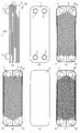
- FIG. 3 shows a plate heat exchanger 100 according to the first embodiment.
- FIG. 2 is an exploded perspective view illustrating a configuration outline of a plate heat exchanger 100 according to the first embodiment.
- 4A and 4B illustrate a rectifier / distributor 201 in Embodiment 1.
- FIG. FIG. 3 is a diagram showing a rectifier / distributor 201 using a flat tube as the slave tube 220 in the first embodiment.
- FIG. 3 shows a rectifier / distributor 201 using a thin tube for the secondary tube 220 in the first embodiment.
- FIG. 6 illustrates a rectifier / distributor 202 in Embodiment 2.
- FIG. 10 is a diagram illustrating an effect of the rectifier / distributor 202 in the second embodiment.
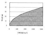
- FIG. 10 is a diagram showing the relationship between the refrigerant flow rate flowing into the main pipe 210 and the inner diameter of the main pipe 210 in the third embodiment.
- FIG. 1 shows a plate heat exchanger 100 according to the first embodiment.
- FIG. 1A is a side view of the plate heat exchanger 100.
- FIG. (2) FIG. 1B is a front view (in the direction of arrow X in FIG. 1A).
- the arrow X direction of Fig.1 (a) is a lamination direction of a plate.
- the front reinforcing side plate 1 in FIG. 1B is located on the outermost side.
- the front reinforcing side plate 1 includes an inflow / outflow pipe 5 for the first fluid A, an inflow / outflow pipe 7 for the first fluid A, an inflow pipe 6 for the second fluid B, and an outflow pipe 8 for the second fluid B.
- the inflow / outflow pipe 5 of the first fluid A and the outflow / inflow pipe 7 of the first fluid A are referred to as “outflow / inflow pipe” for the following reason.
- the plate heat exchanger 100 When the plate heat exchanger 100 is used as an evaporator (heat absorber), the refrigerant (first fluid) flows in from an inflow / outflow pipe 7 of FIG.
- the plate heat exchanger 100 When the plate heat exchanger 100 is used as a condenser (heat radiator), the refrigerant (first fluid) flows in from the inflow / outflow pipe 5 and flows out from the outflow / inflow pipe 7.
- the fluid flows out or flows in when used as an evaporator or a condenser.
- FIG. 1 (c) shows a V-shaped wave shape 9 formed in the first fluid A and the second fluid B (first and second channels 21 and 22 described later).
- a front heat transfer plate 2 is shown.
- the front heat transfer plate 2 has holes 11 to 14 at the four corners that serve as outflow inlets of the first fluid A or the second fluid B.
- FIG. 1 (d) shows that the V-shaped wave shape 10 is placed facing the front heat transfer plate 2 (so that the V-shapes intersect each other), and the first fluid A and the second fluid
- the rear side heat-transfer plate 3 which comprises the B flow path is shown.
- a flow path through which the first fluid A flows is referred to as a first flow path 21, and a flow path through which the second fluid B flows is referred to as a second flow path 22. That is, the first flow path 21 and the second flow path 22 are alternately formed by alternately arranging the front heat transfer plate 2 and the rear heat transfer plate 3.
- FIG. 1E shows the rear reinforcing side plate 4 located on the outermost side.
- 2 is a rear view of the plate heat exchanger 100.
- FIG. (6) FIG. 1F is a diagram showing a state in which the front heat transfer plate 2 and the rear heat transfer plate 3 are overlapped.
- FIG. 1 (f) shows the shape of the front heat transfer plate 2 that is actually visible when viewed in the direction of the arrow X in FIG.
- the wave shape of the side heat transfer plate 3 is indicated by a dotted line.
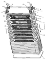
- FIG. 2 is an exploded perspective view showing an outline of the configuration of the plate heat exchanger 100. Note that FIG. 2 does not show a rectifier / distributor 201 described later.
- FIG. 2 is a diagram for illustrating the stacked state of the plates and the flow of the first fluid A and the second fluid B.
- FIG. FIG. 2 shows a case where the plate heat exchanger 100 is used as an evaporator. Therefore, the first fluid A flows in from the inflow / outflow pipe 7, flows through the first flow path 21, and flows out of the outflow / inflow pipe 5.
- the second fluid B flows in from the inflow pipe 6, flows through the second flow path 22, and flows out from the outflow pipe 8. As shown in FIG.
- first flow paths 21 through which the first fluid A flows and second flow paths 22 through which the second fluid B flows are alternately formed between the plates.
- the 1st lamination direction flow path 41 is formed.
- the first stacking direction flow path 41 is a flow path of the first fluid A in the stacking direction X formed by a plurality of holes 13 having the same positions at the four corners and continuous in the stacking direction X, and each first flow direction This is a flow path where the first fluid A branches into the path 21.
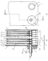
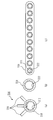
- FIG. 3 is a diagram for explaining the rectifier / distributor 201 included in the plate heat exchanger 100.
- FIG. 3A is a front view of the vicinity of the inflow / outflow pipe 7 corresponding to FIG.
- FIG. 3B shows an AA cross section of FIG. The AA section is cut at a section where the first flow path 21 can be seen continuously.
- An arrow X indicating the stacking direction goes from the front to the back. That is, the side of the front reinforcing side plate 1 is the front, and the side of the rear reinforcing side plate 4 is the back.
- a plurality of plates are arranged in parallel, and a rectifier / distributor 201 is inserted into a first stacking direction flow path 41 configured by flow paths L1 to Ln based on the holes 13 of each plate.
- the rectifier / distributor 201 has a configuration in which a plurality of slave pipes 220 (distribution pipes) are arranged in a plate parallel direction (stacking direction X) on a master pipe 210.
- the secondary tube 220 uses a thin tube (FIG. 9B described later), a flat tube 18 (FIG. 9C described later), or the like.
- the first fluid A is uniformly dispersed in the heat exchange flow path between the plates by the rectifier / distributor 201.
- FIG. 4 is a diagram showing a rectifier / distributor 201 using a flat tube, which will be described later with reference to FIG. As shown in FIG. 9C, the flat tube has a plurality of through holes 221 formed substantially parallel to the longitudinal direction.
- FIG. 5 is a diagram showing a rectifier / distributor 201 using a hollow cylindrical thin tube as the secondary tube 220.
- the rectifier / distributor 201 communicates with the main pipe 210 inserted into the first lamination direction flow path 41 so that the longitudinal direction thereof is the lamination direction X, and the internal space of the main pipe 210, And a secondary pipe 220 disposed in the main pipe 210 at the position of each first flow path 21.
- the secondary tube 220 at least one of a thin tube having a circular inner diameter as shown in FIG. 5 and a flat tube shown in FIG. 4 is used. That is, in FIG. 4, only a flat tube is used, but a thin tube and a flat tube may be mixed and used.
- each of the plurality of sub pipes 220 is inserted into a through hole 211 that has one end portion penetrating inward from the outer side surface of the main pipe 210.
- the main pipe 210 is disposed.
- Each of the plurality of sub-tubes 220 protrudes from the surface on the inner diameter side of the main tube 210 to the internal space of the main tube 210 as a protruding portion 223.
- the liquid distribution in the parallel direction can be adjusted by the insertion amount a of the protruding portion 223 into the internal space of the main tube 210 of the slave tube 220 (the protruding length of the protruding portion 223). That is, the protruding portion 223 becomes a resistance against the first refrigerant A that extends in the longitudinal direction from the end portion on the near side (front reinforcing side plate 1 side) of the main pipe 210. At this time, the resistance to the first refrigerant A can be adjusted by adjusting the insertion amount a of each protrusion 223.
- the insertion amount a is a dimension a in which the end portion of the secondary tube 220 protrudes from the inner diameter side surface of the main tube 210 into the internal space of the main tube 210 as shown in FIG.
- FIG. 3B shows the amount of insertion “a” of the slave tube 220 on the most front side.
- the insertion amount a of the subordinate pipe 220 on the near side is increased (longer), and the insertion amount a is decreased toward the back ( (Short).
- the insertion amount a of each protrusion part 223 is non-uniform
- Non-uniform means that the insertion amount a of the protrusion 223 is not uniform. That is, it is “non-uniform” except when the insertion amounts a of all the protrusions 223 have substantially the same length.
- the insertion amount a of the secondary tube 220 on the front side may be reduced, or the insertion amount a between the front side and the rear side may be increased.
- the insertion amount a of the sub pipe 220 is determined in accordance with the liquid amount or the flow mode of the fluid flowing into the main pipe 210.
- the flat tube used as the secondary tube 220 includes an elliptical tube, a plate-shaped flat tube, an electric sewing tube, a connecting tube in which a plurality of circular tubes are connected, and a flat tube formed by narrowing the circular tube.
- any pipe that has a flat cross section and can distribute the first refrigerant from the internal space of the main pipe 210 to the first flow path 21 is included in the flat pipe.
- the follower tube 220 has a convex shape.
- the “convex shape” means that it protrudes from the outer surface of the main pipe 210 toward the first flow path 21 between the plates. Because of this “convex shape”, alignment of the follower tube 220 and the first flow path 21 corresponding to the follower tube 220 is also easy. That is, when temporarily assembled and brazed, some deformation occurs during brazing. However, because of the “convex shape”, the slave tube 220 does not move to the first flow channel adjacent to the corresponding first flow channel even if some deformation occurs.
- the main pipe 210 is simply formed with “holes and slits” (referred to as concave shapes), the “holes and slits” may be displaced from the corresponding first flow paths due to deformation during brazing. There is. When this deviation occurs, the first fluid A flowing out from the “hole or slit” hits the plate, and uniform distribution to the first flow path becomes impossible.
- the main pipe 210 if only “holes and slits” are formed in the main pipe 210, if there is a distance between the “holes and slits” and the first flow path, the main pipe 210 will stall when the flow rate of the first fluid is small, and the space between the plates May not reach the flow path.
- inconveniences such as “holes and slits” (concave shape) do not occur.
- FIG. 6 is a diagram illustrating a state in which a plurality of resistors 225 are arranged on the main pipe 210.
- FIG. 6A is a view of the main pipe 210 in which the resistor 225 is disposed as viewed from the X direction (FIG. 1A).
- FIG. 6B is a cross-sectional view corresponding to FIG.
- the protruding portion 223 (insertion amount a) of the follower tube 220 extends from the end of the front side (front reinforcing side plate 1 side) to the back side ( The case where it functions as a resistance to the first refrigerant A toward the rear reinforcing side plate 4 side) has been described.
- FIG. 3B the protruding portion 223 (insertion amount a) of the follower tube 220 extends from the end of the front side (front reinforcing side plate 1 side) to the back side ( The case where it functions as a resistance to the first refrigerant A toward the rear reinforcing side plate 4
- 3B is an example, and as shown in FIG. 6, a plurality of resistors 225 may be sequentially arranged inside the main pipe 210 from the front side of the main pipe 210 toward the back side. 3 to 5 can be said to correspond to the case where each of the plurality of resistors 225 in FIG. 6 also serves as the protruding portion 223 of the follower tube 220.
- FIG. 7 is a diagram showing a case where only the protruding portion 223 of the follower tube 220 is formed in a flat shape.
- FIG. 7A corresponds to FIG. 6A
- FIG. 7B corresponds to FIG. 6B.
- FIG. 7B is not a cross section.
- the follower tube 220 may form at least the protrusion 223 in a flat shape.
- the protrusion 223 is formed in a flat shape corresponding to a shape crushed from two directions of the insertion direction X of the main pipe 210 and the direction Y opposite to the insertion direction of the main pipe 210.
- the resistance to the first refrigerant A is adjusted by the amount of insertion a of the protrusion 223.
- the entire follower tube 220 may have a flat shape.
- the projection area of a flat shape may enlarge (expand) the protrusion part 223 of the near side, and may make it small (narrow) as it goes back.
- the follower tube 220 is formed in the convex shape. Therefore, it substantially coincides with the flow path formed between the plates, or the first fluid A is superimposed on this flow path. For this reason, the 1st refrigerant
- coolant A can be reliably distributed to each 1st flow path. Further, as described above, it is easy to align the first flow path 21 and the corresponding follower pipe 220 when the rectifier distributor 201 is assembled.
- the freezing capacity is improved by the uniform distribution of the fluid by the rectifier distributor 201. It is difficult for the liquid to flow into the flow path formed between the plates on the front side of the main pipe 210 due to the inertial force, and high-speed steam tends to flow. For this reason, evaporation is promoted in these flow paths, and freezing occurs due to a rapid temperature drop of the plate.
- the fluid distribution in the main pipe 210 can be made uniform by adjusting the insertion amount a of the sub pipe 220, so that freezing can be suppressed.
- the required number of plates of the heat exchanger for the required capacity of the air conditioner can be minimized by improving the heat exchange performance. Furthermore, since freezing in the heat exchanger can be suppressed, a highly reliable plate heat exchanger can be provided while reducing costs.
- Embodiment 2 FIG.
- the second embodiment will be described with reference to FIGS.
- the second embodiment has a configuration in which a plurality of slave pipes 220 are arranged at the positions of the respective first flow paths.
- the plate heat exchanger 100 including the rectifying distributor 201 inserted into the first stacking direction flow path 41 has been described.
- the rectifier / distributor 201 according to the first embodiment is configured to be inserted in the parallel direction of the follower 220 plate.
- the second embodiment shows a configuration in which a plurality of slave tubes 220 are inserted in the circumferential direction of the main tube 210 at each position of the slave tubes 220 arranged in the plate parallel direction.
- FIG. 8 is a diagram illustrating the rectifier / distributor 202 according to the second embodiment.
- FIG. 9 is a diagram for explaining the effect of the rectifier / distributor 202.
- FIG. 8A is a view of the rectifier / distributor 200 in the X direction.
- a plurality of secondary pipes 220 are inserted into the main pipe 210 in the circumferential direction of the main pipe 210 at each position of the secondary pipe 220. That is, in FIG. 8B, at the position 51 of the slave pipe 220 corresponding to the first flow path 21-1, three slave pipes 220 are inserted in the pipe circumferential direction of the main pipe 210 as shown in FIG. It is. At the position 52 of the slave pipe 220 corresponding to the first flow path 21-2, as in the position 51, three slave pipes 220 are inserted. The same applies to the other positions 53 to 56. As shown in FIG. 8B, the plurality of sub pipes 220 are arranged in the substantially circumferential direction of the main pipe 210 at the positions of the respective first flow paths.
- the first fluid A flowing through the main pipe 210 can be expanded in the pipe circumferential direction of the main pipe 210.
- the secondary pipe 220 distributed pipe
- the pressure loss is generated in the first flow path.
- the pressure loss can be adjusted by changing the size and inner diameter of the follower tube 220 and the number at each position (position 51, position 52, etc.).
- the inner diameter of the flat tube ((c) in FIG. 11) having a plurality of holes is changed, or the flow direction of the first fluid A is changed to the insertion angle ⁇ in the pipe circumferential direction (in FIG. 8). Adjustment is possible in (a)). By these adjustments, it is possible to force the fluid to flow into the region 19 (FIG. 9) on the opposite side to the hole 12 where the fluid is likely to stagnate.
- the flow pattern of the main pipe 210, the shape of the heat transfer plate, and the position of the fluid inlet / outlet on the heat transfer plate, the number of the sub pipes 220 in the parallel direction, the number of the sub pipes 220 in the pipe circumferential direction, or The dimension of the follower tube 220 may be changed.
- Embodiment 3 The third embodiment will be described with reference to FIG.
- the rectifier / distributor 202 of the second embodiment described above a configuration in which a plurality of slave pipes 220 are inserted in the pipe circumferential direction of the main pipe 210 is shown.
- the rectifier / distributor 203 of Embodiment 3 shows a case where the main pipe 210 has a predetermined pipe diameter (inner diameter).
- FIG. 10 is a graph showing the relationship between the refrigerant flow rate (horizontal axis; kg / h) flowing into the main pipe 210 and the inner diameter (vertical axis; mm) of the main pipe 210 of the rectifier distributor 203.
- the hole 13 of the heat transfer plate has a large inner diameter and is easy to form a separated flow.
- gas-liquid deviation occurs in the flow path between the plates, and the effective heat transfer area is reduced or frozen.
- the fluid is R410A
- the flow pattern in the main pipe 210 is an annular flow within the range of the inner diameter indicated by the oblique lines in FIG. 10, and a liquid film of fluid is formed around the pipe.
- the main pipe 210 of the rectifier / distributor 203 has an inner diameter where the incoming first fluid A becomes an annular flow. For this reason, the fluid in which the gas and liquid are evenly mixed easily flows in the flow path between the plates. Therefore, it is possible to provide a highly reliable heat exchanger that not only improves heat exchange performance but also prevents freezing.
- R410A in addition to this refrigerant
- the insertion amount a of the slave pipe 220 into the main pipe 210, the dimension to the flow path side, the inner diameter, the number in the pipe circumferential direction and the parallel direction Adjustment enables detailed flow rate adjustment to each flow path. Therefore, a higher uniform distribution effect of the first fluid A can be obtained.
- FIG. A rectifier / distributor 204 according to the fourth embodiment will be described with reference to FIG.
- the rectifier / distributor 203 of the third embodiment described above the case where the main pipe 210 has a predetermined pipe diameter (inner diameter) has been described.
- the rectifier / distributor 204 of the fourth embodiment a case where a longitudinal groove is formed on the inner surface of the main pipe 210 or the sub pipe 220 will be described.
- FIG. 11 is a diagram showing grooves between the main pipe 210 and the sub pipe 220 in the fourth embodiment.
- (A) of FIG. 11 is an X direction arrow view (equivalent to (a) of FIG. 8) of the rectifying / distributing device 204 of the fourth embodiment.
- the main pipe 210 has a plurality of grooves 212 extending in the longitudinal direction on the inner surface.
- FIG. 11B is a diagram showing a thin tube used as the secondary tube 220.
- FIG. 11C is a view showing a flat tube used as the slave tube 220.
- a plurality of grooves 222 extending in the longitudinal direction are formed on the inner surface of the slave tubes 220. Although a plurality of slave pipes 220 are used, the grooves 222 may be formed in all the slave pipes 220, or the grooves 222 may be formed only in some of the slave pipes 220.
- Grooves are formed in the main pipe 210 and the follower pipe 220 of the rectifier distributor 200, and an annular flow of the first fluid A is easily formed due to the liquid retention effect between the grooves and the increased centrifugal force due to the twist of the groove. Thereby, the same effect as in the third embodiment can be obtained.
- detailed flow rate adjustment to each flow path is possible, and thus a higher uniform distribution effect can be obtained.
- Embodiment 5 FIG.
- the case where grooves are formed on the inner surfaces of the main pipe 210 and the secondary pipe 220 of the rectifier distributor 204 has been described.
- an embodiment of a refrigeration cycle apparatus including a plate heat exchanger 100 including any of the rectifying distributors 201 to 204 of the first to fourth embodiments will be described.
- the refrigeration cycle apparatus in which a compressor, a condenser, an expansion valve, and an evaporator (heat radiator) are sequentially connected by a refrigerant pipe, the refrigeration cycle apparatus is at least one of a condenser and an evaporator.
- the plate heat exchanger provided with the rectifier / distributor according to any one of the first to fourth embodiments is used. According to the refrigeration cycle apparatus of the fifth embodiment, a highly reliable refrigeration cycle apparatus excellent in heat exchange performance can be obtained.
- the refrigeration cycle apparatus has been described as an application example of the plate heat exchanger 100 including the rectifier / distributor according to any of Embodiments 1 to 4.
- the plate heat exchanger 100 can be used in many industrial and household devices equipped with a plate heat exchanger such as air conditioning, power generation, and food sterilization equipment.
- the air conditioner equipped with the plate heat exchanger 100 the amount of power consumption can be suppressed, and the amount of CO 2 emission can also be reduced.
- the pressure loss of the fluid can be reduced, it is possible to use a fluid having a large pressure loss such as a hydrocarbon or a low GWP refrigerant.
- the plate heat exchanger 100 described in the above embodiment includes any one of the rectifier distributors 201 to 204.
- (1) Thereby, the heat exchange with the 1st fluid A and the 2nd fluid B in each flow path is performed uniformly, and an effective heat-transfer area can be utilized without waste. For this reason, a heat exchanger with high heat exchange efficiency can be provided.
- the distribution pipe between the plates is a circular tube or a substantially flat tube and has a convex shape. For this reason, the fluid can flow out to the flow path inlet between the plates.
- the air conditioner equipped with the plate heat exchanger 100 the power consumption can be suppressed and the CO2 emission can be reduced. Therefore, an inexpensive and highly reliable refrigeration cycle apparatus and air conditioner can be provided.
Landscapes
- Engineering & Computer Science (AREA)
- Physics & Mathematics (AREA)
- Thermal Sciences (AREA)
- Mechanical Engineering (AREA)
- General Engineering & Computer Science (AREA)
- Heat-Exchange Devices With Radiators And Conduit Assemblies (AREA)
- Details Of Heat-Exchange And Heat-Transfer (AREA)
Abstract
Priority Applications (5)
| Application Number | Priority Date | Filing Date | Title |
|---|---|---|---|
| CN201180071866.6A CN103649668B (zh) | 2011-06-24 | 2011-06-24 | 板式换热器和冷冻循环装置 |
| US14/124,324 US9772145B2 (en) | 2011-06-24 | 2011-06-24 | Flat plate heat exchanger having fluid distributor inside manifold |
| PCT/JP2011/064580 WO2012176336A1 (fr) | 2011-06-24 | 2011-06-24 | Élément chauffant à plaques et dispositif de cycle de réfrigération |
| GB1322314.4A GB2505829B (en) | 2011-06-24 | 2011-06-24 | Plate heat exchanger and refrigeration cycle apparatus |
| JP2013521401A JP5665983B2 (ja) | 2011-06-24 | 2011-06-24 | プレート式熱交換器及び冷凍サイクル装置 |
Applications Claiming Priority (1)
| Application Number | Priority Date | Filing Date | Title |
|---|---|---|---|
| PCT/JP2011/064580 WO2012176336A1 (fr) | 2011-06-24 | 2011-06-24 | Élément chauffant à plaques et dispositif de cycle de réfrigération |
Publications (1)
| Publication Number | Publication Date |
|---|---|
| WO2012176336A1 true WO2012176336A1 (fr) | 2012-12-27 |
Family
ID=47422207
Family Applications (1)
| Application Number | Title | Priority Date | Filing Date |
|---|---|---|---|
| PCT/JP2011/064580 Ceased WO2012176336A1 (fr) | 2011-06-24 | 2011-06-24 | Élément chauffant à plaques et dispositif de cycle de réfrigération |
Country Status (5)
| Country | Link |
|---|---|
| US (1) | US9772145B2 (fr) |
| JP (1) | JP5665983B2 (fr) |
| CN (1) | CN103649668B (fr) |
| GB (1) | GB2505829B (fr) |
| WO (1) | WO2012176336A1 (fr) |
Cited By (9)
| Publication number | Priority date | Publication date | Assignee | Title |
|---|---|---|---|---|
| CN103759474A (zh) * | 2014-01-28 | 2014-04-30 | 丹佛斯微通道换热器(嘉兴)有限公司 | 板式换热器 |
| WO2015084027A1 (fr) * | 2013-12-03 | 2015-06-11 | 한국원자력연구원 | Système de refroidissement passif d'enceinte de confinement et centrale nucléaire le comprenant |
| WO2015102348A1 (fr) * | 2014-01-06 | 2015-07-09 | 한국원자력연구원 | Système de dissipation passive de la chaleur résiduelle et centrale nucléaire comprenant celui-ci |
| KR101540668B1 (ko) * | 2014-01-06 | 2015-07-31 | 한국원자력연구원 | 피동안전계통 및 이를 구비하는 원전 |
| WO2015120804A1 (fr) * | 2014-02-12 | 2015-08-20 | 丹佛斯微通道换热器(嘉兴)有限公司 | Echangeur thermique à plaques |
| JP2018189352A (ja) * | 2017-04-28 | 2018-11-29 | 株式会社前川製作所 | 熱交換器 |
| WO2019216183A1 (fr) * | 2018-05-11 | 2019-11-14 | 株式会社デンソー | Échangeur de chaleur de type à plaques stratifiées |
| WO2024121984A1 (fr) * | 2022-12-07 | 2024-06-13 | 三菱電機株式会社 | Échangeur thermique, unité extérieure comprenant un échangeur thermique et dispositif de climatisation comprenant une unité extérieure |
| JP7718523B1 (ja) | 2024-02-28 | 2025-08-05 | 株式会社富士通ゼネラル | 熱交換器 |
Families Citing this family (11)
| Publication number | Priority date | Publication date | Assignee | Title |
|---|---|---|---|---|
| KR20150002980A (ko) * | 2013-06-28 | 2015-01-08 | 삼성전자주식회사 | 공기조화기 |
| US20160040942A1 (en) | 2014-08-08 | 2016-02-11 | Halla Visteon Climate Control Corp. | Heat exchanger with integrated noise suppression |
| WO2017042867A1 (fr) * | 2015-09-07 | 2017-03-16 | 三菱電機株式会社 | Colonne stratifiée, échangeur de chaleur et climatiseur |
| EP3458790A4 (fr) * | 2016-05-20 | 2020-01-22 | Modine Manufacturing Company | Échangeur de chaleur et système d'échange de chaleur |
| DK3290822T3 (da) * | 2016-08-30 | 2020-02-24 | Alfa Laval Corp Ab | Pladevarmeveksler til solvarme |
| FR3059408A1 (fr) * | 2016-11-30 | 2018-06-01 | Valeo Systemes Thermiques | Dispositif de distribution d'un fluide refrigerant a l'interieur d'une boite collectrice d'un echangeur thermique |
| FR3059407B1 (fr) * | 2016-11-30 | 2019-10-18 | Valeo Systemes Thermiques | Dispositif de mixage d'un fluide refrigerant a l'interieur d'une boite collectrice d'un echangeur thermique |
| JP7244293B2 (ja) * | 2019-02-19 | 2023-03-22 | 東芝キヤリア株式会社 | 分配管ユニット、プレート式熱交換器および冷凍サイクル装置 |
| CN109945700B (zh) * | 2019-03-26 | 2024-03-29 | 深圳大学 | 一种紧凑式换热结构及热伏发电装置 |
| TWI712771B (zh) * | 2019-05-29 | 2020-12-11 | 國立中央大學 | 用於板式熱交換器之入口分佈器 |
| DE102023211373A1 (de) * | 2023-11-15 | 2025-05-15 | Fraunhofer-Gesellschaft zur Förderung der angewandten Forschung eingetragener Verein | Warmepumpe und Verfahren zu deren Betrieb |
Citations (8)
| Publication number | Priority date | Publication date | Assignee | Title |
|---|---|---|---|---|
| JPH0297899A (ja) * | 1988-09-30 | 1990-04-10 | Matsushita Refrig Co Ltd | 熱交換器 |
| JPH03244995A (ja) * | 1990-02-22 | 1991-10-31 | Sanden Corp | 熱交換器の製造方法 |
| JPH0545487U (ja) * | 1991-10-16 | 1993-06-18 | 東洋ラジエーター株式会社 | 熱交換器 |
| JPH07151488A (ja) * | 1993-11-29 | 1995-06-16 | Sanden Corp | 熱交換器及びその製造方法 |
| JP2001355981A (ja) * | 1993-11-08 | 2001-12-26 | Sharp Corp | 熱交換器 |
| JP2002062082A (ja) * | 2000-08-10 | 2002-02-28 | Daikin Ind Ltd | プレート型熱交換器 |
| JP2008190863A (ja) * | 2008-03-27 | 2008-08-21 | Mitsubishi Electric Corp | プレート熱交換器及びそれを備えた冷凍サイクルシステム |
| JP2010261662A (ja) * | 2009-05-08 | 2010-11-18 | Hisaka Works Ltd | プレート式熱交換器、及びこれを備えた熱交換ユニット |
Family Cites Families (26)
| Publication number | Priority date | Publication date | Assignee | Title |
|---|---|---|---|---|
| US2357156A (en) * | 1942-03-02 | 1944-08-29 | Mcquay Inc | Radiator |
| US2648527A (en) * | 1948-05-25 | 1953-08-11 | Orson A Carnahan | Heat exchanger |
| US2710443A (en) * | 1949-06-07 | 1955-06-14 | Babcock & Wilcox Co | Method of making a restricted orifice tube joint |
| US3731734A (en) * | 1971-05-03 | 1973-05-08 | Ecodyne Corp | Adjustable selective orificing steam condenser |
| GB2159431B (en) * | 1984-05-29 | 1988-04-27 | Shell Int Research | Reactor for non-isothermic reactions and process for the preparation of hydrocarbons using such a reactor |
| US4705103A (en) * | 1986-07-02 | 1987-11-10 | Carrier Corporation | Internally enhanced tubes |
| JP3210062B2 (ja) | 1992-03-23 | 2001-09-17 | 松下冷機株式会社 | 冷媒分流器 |
| IL107850A0 (en) | 1992-12-07 | 1994-04-12 | Multistack Int Ltd | Improvements in plate heat exchangers |
| JPH11101588A (ja) | 1997-09-29 | 1999-04-13 | Hisaka Works Ltd | プレート式熱交換器 |
| US6179051B1 (en) * | 1997-12-24 | 2001-01-30 | Delaware Capital Formation, Inc. | Distributor for plate heat exchangers |
| JP2001050611A (ja) | 1999-08-10 | 2001-02-23 | Ebara Corp | プレート式熱交換器 |
| JP2001141379A (ja) * | 1999-11-11 | 2001-05-25 | Showa Alum Corp | 複式熱交換器 |
| JP4454779B2 (ja) | 2000-03-31 | 2010-04-21 | 株式会社日阪製作所 | プレート式熱交換器 |
| SE516416C2 (sv) * | 2000-05-19 | 2002-01-15 | Alfa Laval Ab | Plattpaket, värmeöverföringsplatta, plattvärmeväxlaresamt anv ändning av värmeöverföringsplatta |
| SE516537C2 (sv) * | 2000-05-19 | 2002-01-29 | Alfa Laval Ab | Plattpaket och plattvärmeväxlare |
| US20030010483A1 (en) * | 2001-07-13 | 2003-01-16 | Yasuo Ikezaki | Plate type heat exchanger |
| US20030116310A1 (en) * | 2001-12-21 | 2003-06-26 | Wittmann Joseph E. | Flat tube heat exchanger core with internal fluid supply and suction lines |
| CN2572309Y (zh) | 2002-06-18 | 2003-09-10 | 广东科龙电器股份有限公司 | 大过冷度的蒸汽压缩制冷循环的冷水机组 |
| US7051540B2 (en) * | 2003-01-27 | 2006-05-30 | Battelle Memorial Institute | Methods for fluid separations, and devices capable of separating fluids |
| CN100398970C (zh) | 2003-10-30 | 2008-07-02 | 乐金电子(天津)电器有限公司 | 把支管的插入深度做得各不相同的超细管道热交换器 |
| US20060101849A1 (en) * | 2004-11-12 | 2006-05-18 | Carrier Corporation | Parallel flow evaporator with variable channel insertion depth |
| JP2006200852A (ja) * | 2005-01-24 | 2006-08-03 | Hitachi Zosen Corp | 吸収式冷凍機における吸収器 |
| US20060174611A1 (en) * | 2005-02-07 | 2006-08-10 | Dilley Roland L | Exhaust gas cooler |
| CN101639304A (zh) * | 2009-08-17 | 2010-02-03 | 三花丹佛斯(杭州)微通道换热器有限公司 | 一种换热器及包括该换热器的热交换装置 |
| CN102042772B (zh) * | 2010-05-14 | 2013-03-06 | 南京工业大学 | 具有介质均分器的层叠板翅结构换热器 |
| JP5585543B2 (ja) * | 2011-06-17 | 2014-09-10 | 株式会社デンソー | 車両用冷却装置 |
-
2011
- 2011-06-24 GB GB1322314.4A patent/GB2505829B/en not_active Expired - Fee Related
- 2011-06-24 WO PCT/JP2011/064580 patent/WO2012176336A1/fr not_active Ceased
- 2011-06-24 US US14/124,324 patent/US9772145B2/en not_active Expired - Fee Related
- 2011-06-24 CN CN201180071866.6A patent/CN103649668B/zh active Active
- 2011-06-24 JP JP2013521401A patent/JP5665983B2/ja not_active Expired - Fee Related
Patent Citations (8)
| Publication number | Priority date | Publication date | Assignee | Title |
|---|---|---|---|---|
| JPH0297899A (ja) * | 1988-09-30 | 1990-04-10 | Matsushita Refrig Co Ltd | 熱交換器 |
| JPH03244995A (ja) * | 1990-02-22 | 1991-10-31 | Sanden Corp | 熱交換器の製造方法 |
| JPH0545487U (ja) * | 1991-10-16 | 1993-06-18 | 東洋ラジエーター株式会社 | 熱交換器 |
| JP2001355981A (ja) * | 1993-11-08 | 2001-12-26 | Sharp Corp | 熱交換器 |
| JPH07151488A (ja) * | 1993-11-29 | 1995-06-16 | Sanden Corp | 熱交換器及びその製造方法 |
| JP2002062082A (ja) * | 2000-08-10 | 2002-02-28 | Daikin Ind Ltd | プレート型熱交換器 |
| JP2008190863A (ja) * | 2008-03-27 | 2008-08-21 | Mitsubishi Electric Corp | プレート熱交換器及びそれを備えた冷凍サイクルシステム |
| JP2010261662A (ja) * | 2009-05-08 | 2010-11-18 | Hisaka Works Ltd | プレート式熱交換器、及びこれを備えた熱交換ユニット |
Cited By (19)
| Publication number | Priority date | Publication date | Assignee | Title |
|---|---|---|---|---|
| US10706974B2 (en) | 2013-12-03 | 2020-07-07 | Korea Atomic Energy Research Institute | Passive cooling system of containment building and nuclear power plant comprising same |
| WO2015084027A1 (fr) * | 2013-12-03 | 2015-06-11 | 한국원자력연구원 | Système de refroidissement passif d'enceinte de confinement et centrale nucléaire le comprenant |
| KR101529529B1 (ko) * | 2013-12-03 | 2015-06-18 | 한국원자력연구원 | 피동격납건물냉각계통 및 이를 구비하는 원전 |
| US10811147B2 (en) | 2014-01-06 | 2020-10-20 | Korea Atomic Energy Research Institute | Passive residual heat removal system and atomic power plant comprising same |
| WO2015102348A1 (fr) * | 2014-01-06 | 2015-07-09 | 한국원자력연구원 | Système de dissipation passive de la chaleur résiduelle et centrale nucléaire comprenant celui-ci |
| KR101540668B1 (ko) * | 2014-01-06 | 2015-07-31 | 한국원자력연구원 | 피동안전계통 및 이를 구비하는 원전 |
| KR101535478B1 (ko) * | 2014-01-06 | 2015-07-09 | 한국원자력연구원 | 피동잔열제거계통 및 이를 구비하는 원전 |
| WO2015113496A1 (fr) * | 2014-01-28 | 2015-08-06 | 丹佛斯微通道换热器(嘉兴)有限公司 | Échangeur de chaleur de type à plaques |
| CN103759474B (zh) * | 2014-01-28 | 2018-01-02 | 丹佛斯微通道换热器(嘉兴)有限公司 | 板式换热器 |
| CN103759474A (zh) * | 2014-01-28 | 2014-04-30 | 丹佛斯微通道换热器(嘉兴)有限公司 | 板式换热器 |
| WO2015120804A1 (fr) * | 2014-02-12 | 2015-08-20 | 丹佛斯微通道换热器(嘉兴)有限公司 | Echangeur thermique à plaques |
| JP7045195B2 (ja) | 2017-04-28 | 2022-03-31 | 株式会社前川製作所 | 熱交換器 |
| JP2018189352A (ja) * | 2017-04-28 | 2018-11-29 | 株式会社前川製作所 | 熱交換器 |
| WO2019216183A1 (fr) * | 2018-05-11 | 2019-11-14 | 株式会社デンソー | Échangeur de chaleur de type à plaques stratifiées |
| WO2024121984A1 (fr) * | 2022-12-07 | 2024-06-13 | 三菱電機株式会社 | Échangeur thermique, unité extérieure comprenant un échangeur thermique et dispositif de climatisation comprenant une unité extérieure |
| JPWO2024121984A1 (fr) * | 2022-12-07 | 2024-06-13 | ||
| JP7718523B1 (ja) | 2024-02-28 | 2025-08-05 | 株式会社富士通ゼネラル | 熱交換器 |
| WO2025182609A1 (fr) * | 2024-02-28 | 2025-09-04 | 株式会社富士通ゼネラル | Échangeur de chaleur |
| JP2025131000A (ja) * | 2024-02-28 | 2025-09-09 | 株式会社富士通ゼネラル | 熱交換器 |
Also Published As
| Publication number | Publication date |
|---|---|
| JP5665983B2 (ja) | 2015-02-04 |
| GB201322314D0 (en) | 2014-01-29 |
| JPWO2012176336A1 (ja) | 2015-02-23 |
| GB2505829A (en) | 2014-03-12 |
| CN103649668B (zh) | 2016-02-17 |
| CN103649668A (zh) | 2014-03-19 |
| GB2505829B (en) | 2017-12-27 |
| US9772145B2 (en) | 2017-09-26 |
| US20140123697A1 (en) | 2014-05-08 |
Similar Documents
| Publication | Publication Date | Title |
|---|---|---|
| JP5665983B2 (ja) | プレート式熱交換器及び冷凍サイクル装置 | |
| US8167029B2 (en) | Plate heat exchanger | |
| US8113270B2 (en) | Tube insert and bi-flow arrangement for a header of a heat pump | |
| US10228170B2 (en) | Refrigerant distributor of micro-channel heat exchanger | |
| JP6214789B2 (ja) | 積層型ヘッダ、熱交換器、及び、空気調和装置 | |
| EP3059542B1 (fr) | Collecteur stratifié, échangeur de chaleur, et climatiseur | |
| US10605534B2 (en) | Plate heat exchanger | |
| CN111936815B (zh) | 分配器以及热交换器 | |
| JP2010216754A (ja) | プレート式熱交換器及び冷凍空調装置 | |
| CN105492855A (zh) | 层叠型集管、换热器以及空调装置 | |
| WO2013191056A1 (fr) | Échangeur de chaleur | |
| JP7045195B2 (ja) | 熱交換器 | |
| JPWO2020100276A1 (ja) | プレート式熱交換器、ヒートポンプ装置およびヒートポンプ式冷暖房給湯システム | |
| EP2990749B1 (fr) | Échangeur de chaleur | |
| US20180156544A1 (en) | Two phase distributor evaporator | |
| JP6188926B2 (ja) | 積層型ヘッダー、熱交換器、及び、空気調和装置 | |
| JP5295330B2 (ja) | プレート式熱交換器及び冷凍空調装置 | |
| US10161659B2 (en) | Refrigerant evaporator | |
| EP4067800B1 (fr) | Échangeur de chaleur | |
| CN111854482B (zh) | 一种热管理系统 | |
| JP4879292B2 (ja) | プレート式熱交換器及び冷凍空調装置 | |
| JP6281422B2 (ja) | 積層型熱交換器 | |
| KR20190075679A (ko) | 쉘앤플레이트 열교환기용 쉘 및 이를 구비한 쉘앤플레이트 열교환기 | |
| HK1117223B (en) | Tube inset and bi-flow arrangement for a header of a heat pump | |
| HK1217531A1 (zh) | 层叠型集管、热交换器以及空调装置 |
Legal Events
| Date | Code | Title | Description |
|---|---|---|---|
| WWE | Wipo information: entry into national phase |
Ref document number: 201180071866.6 Country of ref document: CN |
|
| 121 | Ep: the epo has been informed by wipo that ep was designated in this application |
Ref document number: 11868286 Country of ref document: EP Kind code of ref document: A1 |
|
| ENP | Entry into the national phase |
Ref document number: 2013521401 Country of ref document: JP Kind code of ref document: A |
|
| WWE | Wipo information: entry into national phase |
Ref document number: 14124324 Country of ref document: US |
|
| ENP | Entry into the national phase |
Ref document number: 1322314 Country of ref document: GB Kind code of ref document: A Free format text: PCT FILING DATE = 20110624 |
|
| WWE | Wipo information: entry into national phase |
Ref document number: 1322314.4 Country of ref document: GB |
|
| NENP | Non-entry into the national phase |
Ref country code: DE |
|
| 122 | Ep: pct application non-entry in european phase |
Ref document number: 11868286 Country of ref document: EP Kind code of ref document: A1 |