WO2012176427A1 - Objectif à focale variable et dispositif d'imagerie - Google Patents
Objectif à focale variable et dispositif d'imagerie Download PDFInfo
- Publication number
- WO2012176427A1 WO2012176427A1 PCT/JP2012/003970 JP2012003970W WO2012176427A1 WO 2012176427 A1 WO2012176427 A1 WO 2012176427A1 JP 2012003970 W JP2012003970 W JP 2012003970W WO 2012176427 A1 WO2012176427 A1 WO 2012176427A1
- Authority
- WO
- WIPO (PCT)
- Prior art keywords
- lens
- lens group
- refractive power
- zoom
- zoom lens
- Prior art date
- Legal status (The legal status is an assumption and is not a legal conclusion. Google has not performed a legal analysis and makes no representation as to the accuracy of the status listed.)
- Ceased
Links
Images




Classifications
-
- G—PHYSICS
- G02—OPTICS
- G02B—OPTICAL ELEMENTS, SYSTEMS OR APPARATUS
- G02B13/00—Optical objectives specially designed for the purposes specified below
- G02B13/18—Optical objectives specially designed for the purposes specified below with lenses having one or more non-spherical faces, e.g. for reducing geometrical aberration
-
- G—PHYSICS
- G02—OPTICS
- G02B—OPTICAL ELEMENTS, SYSTEMS OR APPARATUS
- G02B15/00—Optical objectives with means for varying the magnification
- G02B15/14—Optical objectives with means for varying the magnification by axial movement of one or more lenses or groups of lenses relative to the image plane for continuously varying the equivalent focal length of the objective
- G02B15/144—Optical objectives with means for varying the magnification by axial movement of one or more lenses or groups of lenses relative to the image plane for continuously varying the equivalent focal length of the objective having four groups only
- G02B15/1441—Optical objectives with means for varying the magnification by axial movement of one or more lenses or groups of lenses relative to the image plane for continuously varying the equivalent focal length of the objective having four groups only the first group being positive
- G02B15/144105—Optical objectives with means for varying the magnification by axial movement of one or more lenses or groups of lenses relative to the image plane for continuously varying the equivalent focal length of the objective having four groups only the first group being positive arranged +-+-
-
- G—PHYSICS
- G03—PHOTOGRAPHY; CINEMATOGRAPHY; ANALOGOUS TECHNIQUES USING WAVES OTHER THAN OPTICAL WAVES; ELECTROGRAPHY; HOLOGRAPHY
- G03B—APPARATUS OR ARRANGEMENTS FOR TAKING PHOTOGRAPHS OR FOR PROJECTING OR VIEWING THEM; APPARATUS OR ARRANGEMENTS EMPLOYING ANALOGOUS TECHNIQUES USING WAVES OTHER THAN OPTICAL WAVES; ACCESSORIES THEREFOR
- G03B2205/00—Adjustment of optical system relative to image or object surface other than for focusing
- G03B2205/0046—Movement of one or more optical elements for zooming
Definitions
- the present invention relates to a zoom lens and an image pickup apparatus, and more particularly to a zoom lens having a relatively short overall length, a high angle of view and a high zoom ratio, and an image pickup apparatus including such a zoom lens.
- a zoom lens in which a third lens group having a fourth lens group having a negative refractive power is arranged.
- Such a configuration is an arrangement of lens groups in which two telephoto types are arranged, which is advantageous in reducing the total length.
- JP-A-4-296809 JP 2001-350093 A (Example 1) JP2007-279622, etc.
- the present invention has been made in view of the above circumstances, and an object thereof is to provide a zoom lens having a short overall length, a sufficiently wide angle of view, and a high zoom ratio.
- the zoom lens according to the present invention comprises: A first lens group having a positive refractive power, a second lens group having a negative refractive power, a third lens group having a positive refractive power, and a negative refractive power, which are arranged in order from the object side.
- a fourth lens group having When zooming from the wide-angle end to the telephoto end side, the distance between the first lens group and the second lens group gradually increases, the distance between the second lens group and the third lens group gradually decreases, and the third lens group All the lens groups move along the optical axis so that the distance from the fourth lens group gradually increases,
- the focal length of the entire system at the wide angle end is fw
- the focal length of the second lens group is f2
- the focal length of the third lens group is f3
- the following conditional expression ⁇ 2.0 ⁇ fw / f2 ⁇ 0. 8 (1) 0.6 ⁇ fw / f3 ⁇ 1.5 (2) It is characterized by satisfying both.
- substantially composed of the first lens group, the second lens group, the third lens group, and the fourth lens group has substantially no power other than those lens groups. This includes cases where the lens, an optical element other than a lens such as an aperture or a cover glass, a lens flange, a lens barrel, an image sensor, a mechanism portion such as a camera shake correction mechanism, and the like are included. This also applies to the description that “the fourth lens group substantially consists of a 41st lens, a 42nd lens, and a 43rd lens” described later.
- the focal length of the entire system at the wide angle end is fw
- the focal length of the first lens unit is f1
- the focal length of the third lens unit is f3
- the following conditional expression 0.10 ⁇ Fw / f1 ⁇ 0.18 (3) 0.6 ⁇ fw / f3 ⁇ 0.8 (2) " It is preferable that both are satisfied.
- the focal length of the entire system at the wide-angle end is fw and the focal length of the fourth lens unit is f4, the following conditional expression ⁇ 1.0 ⁇ fw / f4 ⁇ 0.2. ... (4) Is preferably satisfied.
- the fourth lens group is arranged in order from the object side and has a positive refractive power, a forty-first lens, a negative refractive power, a forty-second lens, and positive refractive power. It is desirable to comprise a 43rd lens having power.
- the forty-second lens and the forty-third lens are cemented together to form a cemented lens.
- the forty-second lens is made of a material having a higher refractive index than the forty-first and forty-third lenses.
- an imaging apparatus includes the zoom lens according to the present invention described above.
- the zoom lens according to the present invention includes a first lens group having a positive refractive power, a second lens group having a negative refractive power, and a third lens group having a positive refractive power, which are arranged in order from the object side. , And a fourth lens group having a negative refracting power, and the arrangement of the lens group in which two telephoto types are arranged side by side makes it possible to shorten the overall length.
- the zoom lens according to the present invention when zooming from the wide-angle end to the telephoto end side, the distance between the first lens group and the second lens group gradually increases, and the distance between the second lens group and the third lens group increases. Since all the lens groups move along the optical axis so that the distance between the third lens group and the fourth lens group gradually increases, the aberration correction and the amount of movement of the lens group are appropriately controlled It becomes easy to balance, and it becomes possible to obtain a wide zoom ratio and a high zoom ratio.
- conditional expression (1) regulates the power distribution of the second lens group with respect to the entire system, and if the lower limit is not reached, the refractive power of the second lens group becomes too strong, and various aberrations are corrected well. Becomes difficult. On the other hand, if the upper limit value is exceeded, the refractive power of the second lens group becomes too weak, making it difficult to obtain a high zoom ratio while keeping the overall length short.
- conditional expression (2) regulates the power distribution of the third lens group with respect to the entire system.
- the zoom lens of the present invention can achieve a high zoom ratio while keeping the overall length short.
- the conditional expression (3) is for the entire system.
- the power distribution of the first lens group is defined, and if it is below the lower limit, the refractive power of the first lens group becomes too weak, and it becomes difficult to obtain a high zoom ratio while keeping the entire length short. If the value exceeds the upper limit, the refractive power of the first lens unit becomes too strong, and it becomes difficult to correct various aberrations satisfactorily.
- the effect by the conditional expression (2) is basically the same as the above-described effect by the conditional expression (2), but in this case, the effect becomes more remarkable.
- the conditional expression (4) defines the power distribution of the fourth lens group with respect to the entire system. If the lower limit is not reached, the refractive power of the fourth lens group becomes too strong, and the distortion is increased from the intermediate focal length to the telephoto end. Becomes larger. On the other hand, if the upper limit is exceeded, the refractive power of the fourth lens group becomes too weak, making it difficult to obtain a high zoom ratio while keeping the overall length short. When the conditional expression (4) is satisfied, the above problems can be prevented.
- the fourth lens group is arranged in order from the object side, the 41st lens having a positive refractive power, the 42nd lens having a negative refractive power, and the positive lens.
- the 43rd lens having the refracting power it is possible to satisfactorily correct the chromatic aberration and astigmatism of the magnification while increasing the refracting power of the fourth lens group and keeping the entire length short.
- each lens is prevented from causing total reflection of peripheral rays. This is desirable because it can increase the refractive power.
- the forty-second lens is made of a material having a higher refractive index than the forty-first and forty-third lenses, a wider angle of view can be achieved more easily.
- the image pickup apparatus includes the zoom lens according to the present invention that achieves the effects described above. Therefore, the lens portion can be reduced in size and can be imaged with a wide angle of view and a high zoom ratio. Become.
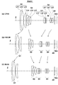
- Sectional view showing the lens configuration of the zoom lens according to Example 1 of the present invention Sectional drawing which shows the lens structure of the zoom lens concerning Example 2 of this invention. Sectional drawing which shows the lens structure of the zoom lens concerning Example 3 of this invention. Sectional drawing which shows the lens structure of the zoom lens concerning Example 4 of this invention. Sectional drawing which shows the lens structure of the zoom lens concerning Example 5 of this invention. Sectional drawing which shows the lens structure of the zoom lens concerning Example 6 of this invention.
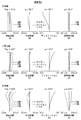
- (A)-(L) are aberration diagrams of the zoom lens according to Example 1 of the present invention.
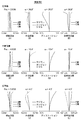
- (A)-(L) are aberration diagrams of the zoom lens according to Example 2 of the present invention.
- (A) to (L) are aberration diagrams of the zoom lens according to Example 3 of the present invention.
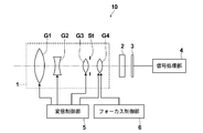
- FIG. 1 is a schematic configuration diagram of an imaging apparatus according to an embodiment of the present invention.
- FIG. 1 is a cross-sectional view illustrating a configuration example of a zoom lens according to an embodiment of the present invention, and corresponds to a zoom lens of Example 1 described later.
- FIGS. 2 to 6 are cross-sectional views showing other configuration examples according to the embodiment of the present invention, and correspond to zoom lenses of Examples 2 to 6 described later, respectively.
- the basic configuration of the example shown in FIGS. 1 to 6 is the same as the example shown in FIG. 3 except that the third lens group G3 is composed of two lenses in the example of FIG. Therefore, here, the zoom lens according to the embodiment of the present invention will be described mainly with reference to FIG.
- the third lens group G3 in the example of FIG. 3 will be described in detail later.
- FIG. 1 the left side is the object side, the right side is the image side, (A) is the infinitely focused state and the optical system arrangement at the wide angle end (shortest focal length state), and (B) is the infinitely focused state.
- the zoom lens according to the embodiment of the present invention includes, in order from the object side, a first lens group G1 having a positive refractive power, a second lens group G2 having a negative refractive power, and a third lens having a positive refractive power.
- a lens group G3 and a fourth lens group G4 having negative refractive power are arranged as a lens group.
- the third lens group G3 includes an aperture stop St.
- the aperture stop St shown here does not necessarily indicate the size or shape, but indicates the position on the optical axis Z.
- FIG. 1 shows an example in which a parallel plate-shaped optical member PP is disposed between the fourth lens group G4 and the image plane Sim.
- Some recent imaging apparatuses employ a 3CCD system that uses a CCD for each color in order to improve image quality.
- a color separation optical system such as a color separation prism is used as a lens system.
- the image plane Sim When applying a zoom lens to an imaging device, various filters such as a cover glass, an infrared cut filter and a low-pass filter are provided between the optical system and the image plane Sim depending on the configuration of the camera side on which the lens is mounted. It is preferable to arrange.
- the optical member PP assumes such a color separation optical system, a cover glass, various filters, and the like.
- all the lens groups of the first lens group G1 to the fourth lens group G4 move along the optical axis Z when zooming. More specifically, when zooming from the wide-angle end to the telephoto end, the first lens group G1 moves monotonically toward the object side, and the second lens group G2 moves toward the image plane Sim side while drawing a curved locus.
- the third lens group G3 monotonously moves to the object side
- the aperture stop St moves integrally with the third lens group G3
- the fourth lens group G4 moves to the object side while drawing a locus of the curve, and as a result,
- the distance between the first lens group G1 and the second lens group G2 gradually increases
- the distance between the second lens group G2 and the third lens group G3 gradually decreases
- the movement trajectory of the first lens group G1 to the fourth lens group G4 when zooming from the wide-angle end to the intermediate position is indicated by a solid arrow between (A) and (B).
- the movement trajectory of the first lens group G1 to the fourth lens group G4 when schematically changing the magnification from the intermediate position to the telephoto end is indicated by a solid line arrow between (B) and (C). It is shown schematically.
- each lens group is not limited to this, and when zooming from the wide-angle end to the telephoto end, the distance between the first lens group G1 and the second lens group G2 gradually increases, and the second lens group G2 and the second lens group G2
- the distance between the third lens group G3 and the third lens group G3 may be moved so that the distance between the third lens group G3 and the fourth lens group G4 gradually increases.
- the first lens group G1 and the third lens group G3 move monotonously.
- the second lens group G2 may be moved in a straight line.
- the first lens group G1 includes, in order from the object side, a first lens L11 having a negative refractive power, a second lens L12 having a positive refractive power, and a third lens L13 having a positive refractive power. Configured. For example, as shown in FIG. 1, the first lens L11 is a negative meniscus lens, the second lens L12 is a biconvex lens, and the third lens L13 is a positive meniscus lens. Can do.
- the second lens group G2 includes, in order from the object side, a fourth lens L21 having a negative refractive power, a fifth lens L22 having a negative refractive power, and a sixth lens L23 having a positive refractive power.
- a fourth lens L21 having a negative refractive power a fifth lens L22 having a negative refractive power
- a sixth lens L23 having a positive refractive power Configured.
- the fourth lens L21 and the fifth lens L22 can be bi-concave lenses
- the sixth lens L23 can be a bi-convex lens.
- the third lens group G3 includes, in order from the object side, a seventh lens L31 having a positive refractive power, an eighth lens L32 having a negative refractive power, and a ninth lens L33 having a positive refractive power. Configured.
- the seventh lens L31 is a biconvex lens
- the eighth lens L32 is a negative meniscus lens
- the ninth lens L33 is a biconvex lens. Can do.
- the fourth lens group G4 includes, in order from the object side, a tenth lens L41 having a positive refractive power, an eleventh lens L42 having a negative refractive power, and a twelfth lens L43 having a positive refractive power. Configured.
- the tenth lens L41, the eleventh lens L42, and the twelfth lens L43 are the 41st lens, the 42nd lens, and the 43rd lens described above, respectively.
- the tenth lens L41 is a biconvex lens
- the eleventh lens L42 is a biconcave lens
- the twelfth lens L43 is a biconvex lens. Can do.
- the eleventh lens L42 and the twelfth lens L43 of the fourth lens group G4 are cemented together to form a cemented lens.
- FIG. 3 has a configuration in which the ninth lens L33 of the third lens group G3 is removed from the configuration described above, and the other configurations are the same as those described above.
- the focal length fw of the entire system at the wide-angle end in Example 1 is the “wide-angle” of the specification f in Table 2. It is shown in the “End” column. Further, the focal length fw of the entire system at the wide-angle end in Example 2 is shown in the same column of Table 5, and so on.
- Table 19 shows values of fw / f2 and fw / f3 related to the conditional expressions (1) and (2) together with values of fw / f1 and fw / f4 related to conditional expressions (3) and (4) described later. These are shown collectively for each example.
- the eleventh lens L42 of the fourth lens group G4 is made of a material having a higher refractive index than the tenth lens L41 and the twelfth lens L43. That is, for example, in Example 1, the refractive indexes of the materials of the eleventh lens L42, the tenth lens L41, and the twelfth lens L43 are 1.88300, 1.50957, and 1.58144, respectively (see Table 1 described later).
- the zoom lens includes a first lens group G1 having a positive refractive power, a second lens group G2 having a negative refractive power, a third lens group G3 having a positive refractive power, which are arranged in order from the object side.
- the lens group is composed of a fourth lens group G4 having negative refractive power and two telephoto types are arranged side by side, the overall length can be shortened.
- the distance between the first lens group G1 and the second lens group G2 is wider at the telephoto end than at the wide-angle end, and the distance between the second lens group G2 and the third lens group G3 is narrower. Since all the lens groups G1 to G4 are moved along the optical axis Z so that the distance between the third lens group G3 and the fourth lens group G4 becomes wider, aberration correction and lens group It becomes easy to balance the movement amount appropriately, and a high zoom ratio is obtained with a wide angle of view.
- the conditional expression (1) defines the power distribution of the second lens group G2 with respect to the entire system. If the lower limit value is not reached, the refractive power of the second lens group G2 becomes too strong, and various aberrations are corrected well. It becomes difficult to do. On the other hand, if the upper limit is exceeded, the refractive power of the second lens group G2 becomes too weak, and it becomes difficult to obtain a high zoom ratio while keeping the entire length short. On the other hand, the conditional expression (2) defines the power distribution of the third lens group G3 with respect to the entire system.
- the refractive power of the third lens group G3 becomes too weak, and the total length is kept short. It becomes difficult to obtain a zoom ratio.
- the upper limit is exceeded, the refractive power of the third lens group G3 becomes too strong, and it becomes difficult to correct various aberrations satisfactorily.
- this zoom lens since the conditional expressions (1) and (2) are satisfied, the above problems can be prevented. In this way, this zoom lens can achieve a high zoom ratio while keeping the overall length short.
- the conditional expression (3) is the first lens for the entire system.
- the power distribution of the group G1 is defined, and if it is below the lower limit, the refractive power of the first lens group G1 becomes too weak, and it becomes difficult to obtain a high zoom ratio while keeping the entire length short. If the value exceeds this value, the refractive power of the first lens group G1 becomes too strong, and it becomes difficult to correct various aberrations satisfactorily.
- the effect by the conditional expression (2) is basically the same as the above-described effect by the conditional expression (2), but in this case, the effect becomes more remarkable. .
- the conditional expression (4) defines the power distribution of the fourth lens group G4 with respect to the entire system, and if the lower limit value is not reached, the refractive power of the fourth lens group G4 becomes too strong, and the telephoto end from the intermediate focal length. The distortion increases over time. On the other hand, if the upper limit is exceeded, the refractive power of the fourth lens group G4 becomes too weak, and it becomes difficult to obtain a high zoom ratio while keeping the entire length short. Since this zoom lens satisfies the conditional expression (4), the above problems can be prevented.
- the fourth lens group G4 has a tenth lens L41 having a positive refractive power, an eleventh lens L42 having a negative refractive power, and a positive refractive power, which are arranged in order from the object side. Since the twelfth lens L43 is provided, the refractive power of the fourth lens group G4 is increased, and the lateral chromatic aberration and astigmatism can be corrected well while keeping the entire length short.
- the eleventh lens L42 and the twelfth lens L43 of the fourth lens group G4 are cemented together to form a cemented lens, so that peripheral rays are prevented from causing total reflection,
- the refractive power of each of the lenses L42 and L43 can be increased.
- the eleventh lens L42 of the fourth lens group G4 is made of a material having a higher refractive index than the tenth lens L41 and the twelfth lens L43, so that the angle of view can be increased more easily. Achieved.
- Table 1 shows basic lens data of the zoom lens of Example 1
- Table 2 shows data relating to zooming
- Table 3 shows aspherical data
- Tables 4 to 18 show basic lens data, zoom-related data, and aspherical data of the zoom lenses of Examples 2 to 6, respectively.
- the meaning of the symbols in the table will be described using the example 1 as an example, but the same applies to the examples 2 to 6.
- the i-th (i 1, 2, 3,...) That sequentially increases toward the image side with the object-side surface of the most object-side component as the first.
- the surface number is indicated
- the Ri column indicates the radius of curvature of the i-th surface
- the Di column indicates the surface interval on the optical axis Z between the i-th surface and the i + 1-th surface.
- the sign of the radius of curvature is positive when the surface shape is convex on the object side and negative when the surface shape is convex on the image side.
- the basic lens data also includes the aperture stop St, and ⁇ (aperture stop) is described in the column of the radius of curvature of the surface corresponding to the aperture stop St.
- D5, D10, D16, and D21 in the basic lens data in Table 1 are surface intervals that change during zooming.
- D5 is the distance between the first lens group G1 and the second lens group G2
- D10 is the distance between the second lens group G2 and the third lens group G3
- D16 is the distance between the third lens group G3 and the fourth lens group G4.
- D21 is the distance between the fourth lens group G4 and the optical member PP.
- D14 indicates the distance between the third lens group G3 and the fourth lens group G4
- D19 indicates the distance between the fourth lens group G4 and the optical member PP.
- Bf represents back focus.
- the zoom-related data in Table 2 includes the focal length (f), F value (Fno.), Total field angle (2 ⁇ ), and various surfaces that change during zooming at the wide-angle end, the intermediate position, and the telephoto end, respectively.
- the values of the intervals (D5, D10, D16, D21) are shown.
- Table 8 shown for Example 3 the surface spacings that change during zooming are indicated as D5, D10, D14, and D19.
- the surface number of the aspheric surface is marked with *, and the paraxial radius of curvature is shown as the radius of curvature of the aspheric surface.
- the aspheric data in Table 3 shows the surface number of the aspheric surface and the aspheric coefficient for each aspheric surface.
- the numerical value “E ⁇ n” (n: integer) of the aspheric data in Table 3 means “ ⁇ 10 ⁇ n”.
- Zd C ⁇ h 2 / ⁇ 1+ (1 ⁇ K ⁇ C 2 ⁇ h 2 ) 1/2 ⁇ + ⁇ Am ⁇ hm
- Zd Depth of aspheric surface (length of a perpendicular line drawn from a point on the aspherical surface at height h to a plane perpendicular to the optical axis where the aspherical vertex contacts)
- h Height (distance from the optical axis to the lens surface)
- C Reciprocal K of paraxial radius of curvature
- values rounded to a predetermined digit are shown.
- degrees are used as the unit of angle and mm is used as the unit of length, but the optical system can be used with proportional expansion or proportional reduction. Other suitable units can also be used.
- Table 19 shows values related to conditional expressions (1) to (4) of the zoom lenses of Examples 1 to 6. Note that the values in Table 19 relate to the d-line.
- FIGS. 7A to 6D show spherical aberration, astigmatism, distortion (distortion aberration) and lateral chromatic aberration (chromatic aberration of magnification) at the wide angle end of the zoom lens of Example 1
- 7E to 7H show spherical aberration, astigmatism, distortion (distortion aberration), and lateral chromatic aberration (chromatic aberration of magnification) at the position, respectively
- spherical aberration, astigmatism, distortion (at the telephoto end) Distortion aberration) and chromatic aberration of magnification (chromatic aberration of magnification) are shown in FIGS. 7I to 7L, respectively.
- Each aberration diagram is based on the d-line (wavelength 587.6 nm), but the spherical aberration diagram also shows aberrations related to the F-line (wavelength 486.1 nm) and C-line (656.3 nm), and the lateral chromatic aberration diagram The aberration regarding F line and C line is shown.
- the sagittal direction is indicated by a solid line, and the tangential direction is indicated by a dotted line.
- Fno Of spherical aberration diagram. Means F value, and ⁇ in other aberration diagrams means half angle of view.
- FIGS. 8A to 8L aberration diagrams of the zoom lens of Example 2 at the wide-angle end, the intermediate position, and the telephoto end are shown in FIGS. 8A to 8L, and the aberrations of Examples 3 to 6 are performed in exactly the same manner.
- the figures are shown in FIGS. 9 to 12, respectively.
- FIG. 1 shows an example in which the optical member PP is disposed between the lens system and the imaging plane, but instead of disposing a low-pass filter, various filters that cut a specific wavelength range, etc. These various filters may be disposed between the lenses, or a coating having the same action as the various filters may be applied to the lens surface of any lens.
- FIG. 13 shows a schematic configuration diagram of an imaging apparatus 10 using the zoom lens 1 of the embodiment of the present invention as an example of the imaging apparatus of the embodiment of the present invention.
- the imaging device include a surveillance camera, a video camera, and an electronic still camera.
- An imaging apparatus 10 illustrated in FIG. 13 includes a zoom lens 1, a filter 2 disposed on the image side of the zoom lens 1, an imaging element 3 that captures an image of a subject formed by the zoom lens 1, and an imaging element 3.
- a signal processing unit 4 that performs arithmetic processing on an output signal from the zoom lens 1, a zooming control unit 5 that performs zooming of the zoom lens 1, and a focus control unit 6 that performs focus adjustment.
- the zoom lens 1 includes a first lens group G1 having a positive refractive power, a second lens group G2 having a negative refractive power, a third lens group G3 having a positive refractive power, arranged in order from the object side.
- the fourth lens group G4 has a negative refractive power.
- the zoom lens 1 when zooming from the wide-angle end to the telephoto end side, as described above, the distance between the first lens group G1 and the second lens group G2 gradually increases, and the second lens group G2 and the third lens group G3. All the lens groups move along the optical axis Z so that the distance between the lens group G3 and the distance between the third lens group G3 and the fourth lens group G4 gradually increase.
- FIG. 13 schematically shows each lens group.
- the image pickup device 3 picks up an optical image formed by the zoom lens 1 and outputs an electrical signal, and the image pickup surface thereof is arranged to coincide with the image surface of the zoom lens 1.
- a CCD or a CMOS can be used as the imaging element 3.
- the lens portion can be reduced in size and can be imaged with a wide angle of view and a high zoom ratio.
- the imaging device 10 is configured so that, for example, a lens having a positive refractive power constituting a part of the third lens group G3 or the entire third lens group G3 is perpendicular to the optical axis Z.
- a shake correction mechanism that corrects shake of a captured image during vibration or camera shake.
- the lens group to be moved is not limited to the third lens group, and other groups or a part thereof may be moved in a direction perpendicular to the optical axis Z to correct a shake of a captured image during vibration or camera shake. Good.
- you may move the image pick-up element 3 instead of a lens.
- the present invention has been described with reference to the embodiments and examples, the present invention is not limited to the above-described embodiments and examples, and various modifications are possible.
- the values of the radius of curvature, the surface interval, the refractive index, the Abbe number, the aspherical coefficient, etc. of each lens component are not limited to the values shown in the above numerical examples, and can take other values.
Landscapes
- Physics & Mathematics (AREA)
- General Physics & Mathematics (AREA)
- Optics & Photonics (AREA)
- Lenses (AREA)
Abstract
La présente invention a pour objet de réduire la longueur globale d'un objectif à focale variable et d'obtenir un large champ optique ainsi qu'un rapport de grossissement élevé dans un tel objectif. L'objectif à focale variable est conçu en disposant, dans l'ordre depuis le côté objet : un premier groupe de lentilles (G1) ayant une puissance réfractive positive ; un deuxième groupe de lentilles (G2) ayant une puissance réfractive négative ; un troisième groupe de lentilles (G3) ayant une puissance réfractive positive ; et un quatrième groupe de lentilles (G4) ayant une puissance réfractive négative. De plus, la configuration est telle que, lorsqu'on modifie le grossissement depuis le côté grand-angle vers le côté téléobjectif, tous les groupes de lentilles se déplacent le long de l'axe optique (Z) d'une manière telle que l'espacement entre le premier groupe de lentilles (G1) et le deuxième groupe de lentilles (G2) augmente progressivement, que l'espacement entre le deuxième groupe de lentilles (G2) et le troisième groupe de lentilles (G3) diminue progressivement et que l'espacement entre le troisième groupe de lentilles (G3) et le quatrième groupe de lentilles (G4) augmente progressivement. En outre, soit fw la distance focale de l'ensemble du système au niveau du côté grand-angle, f2 la distance focale du deuxième groupe de lentilles et f3 la distance focale du troisième groupe de lentilles, les expressions conditionnelles suivantes sont satisfaites : -2,0 < fw/f2 < -0,8… (1) ; et 0,6 < fw/f3 < 1,5… (2).
Applications Claiming Priority (2)
| Application Number | Priority Date | Filing Date | Title |
|---|---|---|---|
| JP2011-138435 | 2011-06-22 | ||
| JP2011138435 | 2011-06-22 |
Publications (1)
| Publication Number | Publication Date |
|---|---|
| WO2012176427A1 true WO2012176427A1 (fr) | 2012-12-27 |
Family
ID=47422285
Family Applications (1)
| Application Number | Title | Priority Date | Filing Date |
|---|---|---|---|
| PCT/JP2012/003970 Ceased WO2012176427A1 (fr) | 2011-06-22 | 2012-06-19 | Objectif à focale variable et dispositif d'imagerie |
Country Status (1)
| Country | Link |
|---|---|
| WO (1) | WO2012176427A1 (fr) |
Cited By (3)
| Publication number | Priority date | Publication date | Assignee | Title |
|---|---|---|---|---|
| CN107976789A (zh) * | 2017-12-27 | 2018-05-01 | 东莞市宇瞳光学科技股份有限公司 | 一种大视场角机器视觉镜头 |
| TWI774306B (zh) * | 2021-04-01 | 2022-08-11 | 大陸商信泰光學(深圳)有限公司 | 成像鏡頭(五十九) |
| US12124016B2 (en) | 2021-04-01 | 2024-10-22 | Sintai Optical (Shenzhen) Co., Ltd. | Lens assembly |
Citations (7)
| Publication number | Priority date | Publication date | Assignee | Title |
|---|---|---|---|---|
| JPS60178421A (ja) * | 1984-02-27 | 1985-09-12 | Canon Inc | コンパクトなズ−ムレンズ |
| JPH01178912A (ja) * | 1987-12-29 | 1989-07-17 | Asahi Optical Co Ltd | 広角を包括するコンパクトな高変倍比ズームレンズ |
| JPH0383005A (ja) * | 1989-08-28 | 1991-04-09 | Minolta Camera Co Ltd | 広角域を含む高変倍率ズームレンズ系 |
| JPH04296809A (ja) * | 1991-03-27 | 1992-10-21 | Olympus Optical Co Ltd | ズームレンズ |
| JPH075361A (ja) * | 1993-06-15 | 1995-01-10 | Olympus Optical Co Ltd | ズームレンズ |
| JPH11109241A (ja) * | 1997-10-03 | 1999-04-23 | Minolta Co Ltd | ズームレンズ系 |
| JP2005284097A (ja) * | 2004-03-30 | 2005-10-13 | Nikon Corp | 防振機能を有するズームレンズ |
-
2012
- 2012-06-19 WO PCT/JP2012/003970 patent/WO2012176427A1/fr not_active Ceased
Patent Citations (7)
| Publication number | Priority date | Publication date | Assignee | Title |
|---|---|---|---|---|
| JPS60178421A (ja) * | 1984-02-27 | 1985-09-12 | Canon Inc | コンパクトなズ−ムレンズ |
| JPH01178912A (ja) * | 1987-12-29 | 1989-07-17 | Asahi Optical Co Ltd | 広角を包括するコンパクトな高変倍比ズームレンズ |
| JPH0383005A (ja) * | 1989-08-28 | 1991-04-09 | Minolta Camera Co Ltd | 広角域を含む高変倍率ズームレンズ系 |
| JPH04296809A (ja) * | 1991-03-27 | 1992-10-21 | Olympus Optical Co Ltd | ズームレンズ |
| JPH075361A (ja) * | 1993-06-15 | 1995-01-10 | Olympus Optical Co Ltd | ズームレンズ |
| JPH11109241A (ja) * | 1997-10-03 | 1999-04-23 | Minolta Co Ltd | ズームレンズ系 |
| JP2005284097A (ja) * | 2004-03-30 | 2005-10-13 | Nikon Corp | 防振機能を有するズームレンズ |
Cited By (4)
| Publication number | Priority date | Publication date | Assignee | Title |
|---|---|---|---|---|
| CN107976789A (zh) * | 2017-12-27 | 2018-05-01 | 东莞市宇瞳光学科技股份有限公司 | 一种大视场角机器视觉镜头 |
| CN107976789B (zh) * | 2017-12-27 | 2023-07-07 | 东莞市宇瞳光学科技股份有限公司 | 一种大视场角机器视觉镜头 |
| TWI774306B (zh) * | 2021-04-01 | 2022-08-11 | 大陸商信泰光學(深圳)有限公司 | 成像鏡頭(五十九) |
| US12124016B2 (en) | 2021-04-01 | 2024-10-22 | Sintai Optical (Shenzhen) Co., Ltd. | Lens assembly |
Similar Documents
| Publication | Publication Date | Title |
|---|---|---|
| JP5616534B2 (ja) | ズームレンズおよび撮像装置 | |
| JP5745188B2 (ja) | ズームレンズおよび撮像装置 | |
| WO2012137496A1 (fr) | Lentille de zoom et dispositif de prise d'image | |
| WO2014006841A1 (fr) | Lentille à focale variable et dispositif d'imagerie | |
| WO2013031188A1 (fr) | Objectif à focale variable et dispositif d'imagerie | |
| WO2013038610A1 (fr) | Système optique d'agrandissement variable et appareil d'imagerie | |
| JP5837931B2 (ja) | ズームレンズおよび撮像装置 | |
| JP5580940B2 (ja) | ズームレンズおよび撮像装置 | |
| WO2013031180A1 (fr) | Objectif à focale variable et dispositif d'imagerie | |
| WO2013031185A1 (fr) | Objectif à focale variable et dispositif d'imagerie | |
| JP5840685B2 (ja) | ズームレンズおよび撮像装置 | |
| WO2012176427A1 (fr) | Objectif à focale variable et dispositif d'imagerie | |
| WO2013031110A1 (fr) | Objectif à focale variable et dispositif d'imagerie | |
| JPWO2012176389A1 (ja) | ズームレンズおよび撮像装置 | |
| JP5778276B2 (ja) | ズームレンズおよび撮像装置 | |
| JP5335373B2 (ja) | ズームレンズおよび撮像装置 | |
| JP5785333B2 (ja) | ズームレンズおよび撮像装置 | |
| WO2012176413A1 (fr) | Objectif à focale variable et dispositif d'imagerie | |
| WO2012176426A1 (fr) | Objectif à focale variable et dispositif d'imagerie | |
| WO2013031179A1 (fr) | Objectif à focale variable et dispositif d'imagerie | |
| WO2013031178A1 (fr) | Objectif à focale variable et dispositif d'imagerie | |
| WO2013031181A1 (fr) | Objectif à focale variable et dispositif d'imagerie | |
| WO2013031109A1 (fr) | Objectif à focale variable et dispositif d'imagerie | |
| WO2013031176A1 (fr) | Objectif à focale variable et dispositif d'imagerie | |
| JP2010085884A (ja) | ズームレンズおよび撮像装置 |
Legal Events
| Date | Code | Title | Description |
|---|---|---|---|
| 121 | Ep: the epo has been informed by wipo that ep was designated in this application |
Ref document number: 12802459 Country of ref document: EP Kind code of ref document: A1 |
|
| NENP | Non-entry into the national phase |
Ref country code: DE |
|
| 122 | Ep: pct application non-entry in european phase |
Ref document number: 12802459 Country of ref document: EP Kind code of ref document: A1 |
|
| NENP | Non-entry into the national phase |
Ref country code: JP |