WO2012176493A1 - Lampe aux halogénures métalliques exempte de mercure pour véhicule et dispositif de lampe aux halogénures - Google Patents
Lampe aux halogénures métalliques exempte de mercure pour véhicule et dispositif de lampe aux halogénures Download PDFInfo
- Publication number
- WO2012176493A1 WO2012176493A1 PCT/JP2012/054168 JP2012054168W WO2012176493A1 WO 2012176493 A1 WO2012176493 A1 WO 2012176493A1 JP 2012054168 W JP2012054168 W JP 2012054168W WO 2012176493 A1 WO2012176493 A1 WO 2012176493A1
- Authority
- WO
- WIPO (PCT)
- Prior art keywords
- metal halide
- lamp
- mercury
- halide lamp
- electrode
- Prior art date
- Legal status (The legal status is an assumption and is not a legal conclusion. Google has not performed a legal analysis and makes no representation as to the accuracy of the status listed.)
- Ceased
Links
Images



Classifications
-
- H—ELECTRICITY
- H01—ELECTRIC ELEMENTS
- H01J—ELECTRIC DISCHARGE TUBES OR DISCHARGE LAMPS
- H01J61/00—Gas-discharge or vapour-discharge lamps
- H01J61/02—Details
- H01J61/12—Selection of substances for gas fillings; Specified operating pressure or temperature
- H01J61/18—Selection of substances for gas fillings; Specified operating pressure or temperature having a metallic vapour as the principal constituent
- H01J61/22—Selection of substances for gas fillings; Specified operating pressure or temperature having a metallic vapour as the principal constituent vapour of an alkali metal
-
- H—ELECTRICITY
- H01—ELECTRIC ELEMENTS
- H01J—ELECTRIC DISCHARGE TUBES OR DISCHARGE LAMPS
- H01J5/00—Details relating to vessels or to leading-in conductors common to two or more basic types of discharge tubes or lamps
- H01J5/50—Means forming part of the tube or lamps for the purpose of providing electrical connection to it
- H01J5/54—Means forming part of the tube or lamps for the purpose of providing electrical connection to it supported by a separate part, e.g. base
- H01J5/56—Shape of the separate part
-
- H—ELECTRICITY
- H01—ELECTRIC ELEMENTS
- H01J—ELECTRIC DISCHARGE TUBES OR DISCHARGE LAMPS
- H01J61/00—Gas-discharge or vapour-discharge lamps
- H01J61/02—Details
- H01J61/04—Electrodes; Screens; Shields
- H01J61/06—Main electrodes
-
- H—ELECTRICITY
- H01—ELECTRIC ELEMENTS
- H01J—ELECTRIC DISCHARGE TUBES OR DISCHARGE LAMPS
- H01J61/00—Gas-discharge or vapour-discharge lamps
- H01J61/02—Details
- H01J61/04—Electrodes; Screens; Shields
- H01J61/06—Main electrodes
- H01J61/073—Main electrodes for high-pressure discharge lamps
- H01J61/0735—Main electrodes for high-pressure discharge lamps characterised by the material of the electrode
-
- H—ELECTRICITY
- H01—ELECTRIC ELEMENTS
- H01J—ELECTRIC DISCHARGE TUBES OR DISCHARGE LAMPS
- H01J61/00—Gas-discharge or vapour-discharge lamps
- H01J61/02—Details
- H01J61/12—Selection of substances for gas fillings; Specified operating pressure or temperature
- H01J61/125—Selection of substances for gas fillings; Specified operating pressure or temperature having an halogenide as principal component
-
- H—ELECTRICITY
- H01—ELECTRIC ELEMENTS
- H01J—ELECTRIC DISCHARGE TUBES OR DISCHARGE LAMPS
- H01J61/00—Gas-discharge or vapour-discharge lamps
- H01J61/02—Details
- H01J61/30—Vessels; Containers
- H01J61/34—Double-wall vessels or containers
-
- H—ELECTRICITY
- H01—ELECTRIC ELEMENTS
- H01J—ELECTRIC DISCHARGE TUBES OR DISCHARGE LAMPS
- H01J61/00—Gas-discharge or vapour-discharge lamps
- H01J61/82—Lamps with high-pressure unconstricted discharge having a cold pressure > 400 Torr
- H01J61/825—High-pressure sodium lamps
-
- H—ELECTRICITY
- H01—ELECTRIC ELEMENTS
- H01J—ELECTRIC DISCHARGE TUBES OR DISCHARGE LAMPS
- H01J61/00—Gas-discharge or vapour-discharge lamps
- H01J61/82—Lamps with high-pressure unconstricted discharge having a cold pressure > 400 Torr
- H01J61/827—Metal halide arc lamps
Definitions
- Embodiments of the present invention relate to a mercury-free metal halide lamp and a metal halide lamp device used for a headlight of a vehicle such as an automobile.
- the metal halide lamp has a structure in which a pair of electrodes are provided inside an arc tube filled with a metal halide or a rare gas.
- radioactive material may be used to suppress flicker.
- thorium has been sealed in the discharge space as a metal halide, or thorium oxide has been mixed with the electrode.
- thorium is an environmentally hazardous substance, it is desired not to use thorium, and so-called thorium-free use without thorium is required.
- JP 2010-86742 A Special table 2010-541129 Special table 2010-521717
- the problem to be solved by the present invention is to provide a mercury-free metal halide lamp for vehicles that can suppress flickering and electrode deformation and has a lower power than conventional and does not contain radioactive substances such as thorium.
- a mercury-free metal halide lamp includes an airtight container having a light emitting part having a discharge space therein, a metal halide and a rare gas sealed in the discharge space, and the discharge space.
- a pair of electrodes whose tip portions are opposed to each other, and the electrodes and the discharge space do not contain thorium, and the power supplied to the lamp during stable lighting is P (W), after the lamp is started
- P (W) is 20 ⁇ P ⁇ 30, W L / D (W / mm) satisfies 4300 ⁇ W L / D ⁇ 7400.
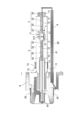
- FIG. 1 is a diagram for explaining a metal halide lamp according to a first embodiment of the present invention
- FIG. 2 is a diagram for explaining a cross section of the metal halide lamp according to the first embodiment.
- the metal halide lamp of the present embodiment can be used as a light source for a headlamp such as an automobile, and includes an inner tube 1 as an airtight container.
- the inner tube 1 has an elongated shape, and a substantially elliptical light emitting portion 11 is formed near the center thereof.
- a plate-like seal portion 12 formed by a pinch seal is formed at both ends of the light emitting portion 11, and a cylindrical portion 14 is continuously formed at both ends via a boundary portion 13.
- the inner tube 1 is preferably made of a material having heat resistance and translucency, such as quartz glass. Further, the seal portion 12 may be formed in a cylindrical shape by being formed by a shrink seal.
- a discharge space 111 is formed that has a substantially cylindrical shape at the center and is tapered toward both ends.
- the discharge space 111 is filled with the metal halide 2 and the rare gas.
- the metal halide 2 is composed of sodium iodide, scandium iodide, zinc iodide, and indium bromide. However, thorium halide, which is a radioactive substance, is not included.
- the total enclosed amount of the metal halide 2 is set to 0.1 mg to 0.3 mg in order to set the lamp voltage to a suitable value.
- the combination of the metal halides 2 is not limited to this, and tin and cesium halides may be added.
- Xenon is used as the rare gas.
- the pressure of this rare gas is 12 atm to 15 atm.
- the rare gas may be a mixed gas of xenon and neon, argon, krypton, or the like.
- the lamp of the present embodiment is a mercury-free metal halide lamp.
- This “mercury-free” means that it does not substantially contain mercury.
- substantially does not contain mercury is not limited to the case where the amount of mercury enclosed is 0 mg, but is equivalent to almost no encapsulation compared to a conventional metal halide lamp containing mercury. It should be construed to include the case of enclosing a quantity of mercury, for example, less than 2 mg, preferably 1 mg or less per ml.
- the electrode mounts 3 are sealed to the seal portions 12 formed on both sides of the light emitting portion 11, respectively.
- the electrode mount 3 includes a metal foil 31, an electrode 32, a coil 33 and a lead wire 34.
- the metal foil 31 is a thin plate member made of, for example, molybdenum.
- the electrode 32 is a rod-shaped member made of tungsten doped with a small amount of aluminum, silicon, or potassium, for example, so-called doped tungsten.
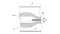
- One end of the metal foil 31 is welded so as to be placed on the end of the light emitting portion 11 side of the metal foil 31, and the other end protrudes into the discharge space 111, and the tip portions of the metal foil 31 face each other while maintaining a predetermined distance. So as to face each other.
- the diameter D is, for example, 0.25 mm.
- the distance between the tips of the electrodes 32 is preferably positioned in the range of 3.7 mm to 4.4 mm when observed through the outer tube 5.
- the coil 33 is a metal wire made of, for example, doped tungsten, and is spirally wound around the shaft portion of the electrode 32 sealed to the seal portion 12.
- the lead wire 34 is a metal wire made of molybdenum, for example.
- One end of the lead wire 34 is connected so as to be placed on the end portion of the metal foil 31 on the distal side from the light emitting portion 11, and the other end extends substantially parallel to the tube axis to the outside of the inner tube 1.
- One end of an L-shaped support wire 35 made of nickel, for example, is connected to the lead wire 34 extending distally from the front side of the lamp, that is, the socket 6 by laser welding.
- a sleeve 4 made of ceramic is attached to the support wire 35 at a portion extending in parallel with the inner tube 1.
- a cylindrical outer tube 5 is provided substantially concentrically with the inner tube 1 so as to cover the light emitting portion 11 outside the inner tube 1 configured as described above. These inner and outer pipes are connected by welding the end portions of the outer pipe 5 in the vicinity of the cylindrical portion 14 of the inner pipe 1. Gas is sealed in a closed space 51 formed between the inner tube 1 and the outer tube 5.
- a gas capable of dielectric barrier discharge for example, one kind of gas selected from neon, argon, xenon and nitrogen or a mixed gas can be used.
- the gas pressure is desirably 0.3 atm or less, particularly 0.1 atm or less.
- the outer tube 5 is preferably made of a material having a thermal expansion coefficient close to that of the inner tube 1 and having an ultraviolet blocking property. For example, quartz glass to which an oxide such as titanium, cerium, or aluminum is added is used. can do.
- a socket 6 is connected to one end of the inner tube 1 to which the outer tube 5 is connected. These connections are made by attaching a metal band 71 to the outer peripheral surface of the outer tube 5 and holding the metal band 71 with a metal tongue piece 72 formed protruding from the socket 6. Further, a bottom terminal 81 is formed at the bottom of the socket 6, and a side terminal 82 is formed at the side, and a lead wire 34 and a support wire 35 are connected to the bottom terminal 81 and the side terminal 82, respectively. .
- the metal halide lamp constituted by these is connected to a lighting circuit (not shown) so that the bottom terminal 81 is on the high voltage side and the side terminal 82 is on the low voltage side, and lamp power (power supplied to the lamp) at the time of starting.
- a lighting circuit not shown
- lamp power power supplied to the lamp
- FIG. 3 shows the change in lamp power from the start of the metal halide lamp of the present embodiment to 50 seconds.
- the current and voltage between the lamp and the lighting circuit are measured and converted into electric power.
- one second or more high-voltage pulse 10kV is applied to the lamp, so is the time breakdown, not considered in the integration of W L. If the electrode diameter D is 0.25 mm, the W L / D of this lamp is 5888 W / mm.
- Comparative Example 1 The reason why the flicker occurred at the initial stage in the lamp of Comparative Example 1 is that the spot that is the starting point of the arc was not stably formed on the electrode. Comparative Example 1 is the integrated value W L of the lamp power is reduced, because the diameter D of the electrode is the case is large, it tends to electrode temperature is lowered. If the electrode temperature is low, the spot is not stable because the electron emission is low even if the spot is formed. Therefore, flickering occurs due to the movement of the spot.
- Comparative Example 2 is a case where the integrated value W L of the lamp power is large and the electrode diameter D is small, the electrode temperature tends to increase. However, spots are difficult to occur when the electrode temperature is too high. When the spot is not generated, the electrode temperature is maintained at a high temperature. Therefore, if the spot is continued for a long time, the electrode is burdened and the electrode is thermally deformed.
- the inventor further examined and found that there is no problem if a spot is generated within 20 to 30 seconds from the start of the lamp. However, if a spot is not formed even after 40 seconds, a heavy burden is placed on the electrode.
- the electrode temperature when the lamp power falls after starting is important.
- the temperature for stably forming the spot is about 2000 ° C. at an electrode temperature measured by a radiation thermometer at a point distant from the tip of the electrode by a diameter D. If it is 1800 ° C., an unstable spot is likely to be generated. Spots are less likely to occur within 40 seconds when the temperature is °C.
- FIGS. 4 is a diagram for explaining W L / D and the flicker OK probability
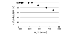
- FIG. 5 is a diagram for explaining W L / D and the probability that a spot will occur on the electrode within 40 seconds. The number of lamps tested was 20.
- W L / D is significantly suppress the occurrence of flicker if 4300W / mm or more, W L / D is 7400W / mm or less value, if after lamp starting 40 seconds elapsed Since the spots can be generated on the electrodes with high probability before the deformation, the deformation of the electrodes can be suppressed. Therefore, W L / D (W / mm) may be 4300 ⁇ W L / D ⁇ 7400, and if W L / D (W / mm) is 4900 ⁇ W L / D ⁇ 6700, High effect can be obtained.
- WL can also be increased or decreased by adjusting the timing or rate at which power is reduced by the lighting circuit.
- the lamp power at the start and at the stable time is set to be in the range of 50 W to 60 W at the start and from 20 W to 30 W at the stable from the viewpoint of the rise of the luminous flux and the lamp life. It is desirable to adjust W L within a range of 1200 W to 1600 W and D within a range of 0.22 mm to 0.30 mm.
- the inner diameter R of the light emitting portion 1 in the substantially central portion in the tube axis direction is 1.5 to 2.3 mm
- the thickness T in the substantially central portion of the light emitting portion 1 in the tube axis direction is 1.2 to 1.8 mm
- the light emitting portion 1 The inner volume of the metal halide is preferably 15 to 23 mm 3
- the total enclosed amount of the metal halide 2 is preferably 0.05 to 0.25 mg (0.0025 to 0.0125 mg / mm 3 ).
- the inner diameter R of the light emitting part 1 is 1.8 to 2.2 mm
- the wall thickness T of the light emitting part 1 is 1.4 to 1.7 mm
- the inner volume of the light emitting part 1 is 17 to 21 mm 3
- the total inclusion of the metal halide 2 is included.
- the optimum amount is 0.10 to 0.20 mg (0.005 to 0.010 mg / mm 3 ).
- the metal halide lamp may be a lamp integrated with the starting lighting circuit, a lamp integrated with the starting lighting circuit and the stable lighting circuit, or the like.
- the shape of the electrode 32 is, for example, as shown in FIG. 6, a stepped shape in which the diameter of the distal end is larger than the diameter of the proximal end, a shape having a spherical shape with a large distal end, one electrode diameter and the other
- the electrode may have different electrode diameters. Note that in the case of an electrode shape in which the diameters of the distal end and the proximal end are different as shown in FIG.
- the electrode material may be pure tungsten, rhenium tungsten, or the like. In short, any electrode that does not contain thorium oxide, which is a radioactive substance, may be used.
Landscapes
- Discharge Lamp (AREA)
- Discharge Lamps And Accessories Thereof (AREA)
- Vessels And Coating Films For Discharge Lamps (AREA)
Abstract
Priority Applications (3)
| Application Number | Priority Date | Filing Date | Title |
|---|---|---|---|
| US14/128,127 US8836217B2 (en) | 2011-06-23 | 2012-02-21 | Mercury-free metal halide lamp for vehicle and metal halide lamp device |
| EP12802474.2A EP2725604A4 (fr) | 2011-06-23 | 2012-02-21 | Lampe aux halogénures métalliques exempte de mercure pour véhicule et dispositif de lampe aux halogénures |
| CN201280030259.XA CN103748657B (zh) | 2011-06-23 | 2012-02-21 | 车辆用的无汞金属卤化物灯及金属卤化物灯装置 |
Applications Claiming Priority (2)
| Application Number | Priority Date | Filing Date | Title |
|---|---|---|---|
| JP2011138993 | 2011-06-23 | ||
| JP2011-138993 | 2011-06-23 |
Publications (1)
| Publication Number | Publication Date |
|---|---|
| WO2012176493A1 true WO2012176493A1 (fr) | 2012-12-27 |
Family
ID=47422344
Family Applications (1)
| Application Number | Title | Priority Date | Filing Date |
|---|---|---|---|
| PCT/JP2012/054168 Ceased WO2012176493A1 (fr) | 2011-06-23 | 2012-02-21 | Lampe aux halogénures métalliques exempte de mercure pour véhicule et dispositif de lampe aux halogénures |
Country Status (5)
| Country | Link |
|---|---|
| US (1) | US8836217B2 (fr) |
| EP (1) | EP2725604A4 (fr) |
| JP (1) | JPWO2012176493A1 (fr) |
| CN (1) | CN103748657B (fr) |
| WO (1) | WO2012176493A1 (fr) |
Cited By (3)
| Publication number | Priority date | Publication date | Assignee | Title |
|---|---|---|---|---|
| CN104733281A (zh) * | 2013-12-20 | 2015-06-24 | 东芝照明技术株式会社 | 放电灯及车辆用灯具 |
| JP2016181397A (ja) * | 2015-03-24 | 2016-10-13 | 東芝ライテック株式会社 | 放電ランプ |
| JP2018508113A (ja) * | 2015-03-20 | 2018-03-22 | コーニンクレッカ フィリップス エヌ ヴェKoninklijke Philips N.V. | 高輝度放電ランプ |
Families Citing this family (2)
| Publication number | Priority date | Publication date | Assignee | Title |
|---|---|---|---|---|
| JP2017098009A (ja) * | 2015-11-20 | 2017-06-01 | 東芝ライテック株式会社 | 放電ランプ |
| JP2018085222A (ja) * | 2016-11-24 | 2018-05-31 | 東芝ライテック株式会社 | 放電ランプ、車両用灯具、および車両用照明装置 |
Citations (6)
| Publication number | Priority date | Publication date | Assignee | Title |
|---|---|---|---|---|
| JP2005142138A (ja) * | 2003-10-16 | 2005-06-02 | Toshiba Lighting & Technology Corp | メタルハライドランプおよび照明装置 |
| JP2006286384A (ja) * | 2005-03-31 | 2006-10-19 | Harison Toshiba Lighting Corp | 自動車用放電ランプ |
| JP2008262855A (ja) * | 2007-04-13 | 2008-10-30 | Harison Toshiba Lighting Corp | 自動車前照灯用メタルハライドランプ |
| JP2010086742A (ja) | 2008-09-30 | 2010-04-15 | Harison Toshiba Lighting Corp | 放電ランプおよび放電ランプ装置 |
| JP2010521771A (ja) | 2007-03-12 | 2010-06-24 | コーニンクレッカ フィリップス エレクトロニクス エヌ ヴィ | 高効率の低電力放電ランプ |
| JP2010541129A (ja) | 2007-09-24 | 2010-12-24 | コーニンクレッカ フィリップス エレクトロニクス エヌ ヴィ | トリウムを有さない放電ランプ |
Family Cites Families (6)
| Publication number | Priority date | Publication date | Assignee | Title |
|---|---|---|---|---|
| JP3728983B2 (ja) * | 1999-06-25 | 2005-12-21 | スタンレー電気株式会社 | メタルハライドランプおよび車両用前照灯 |
| JP4890809B2 (ja) * | 2005-07-28 | 2012-03-07 | ハリソン東芝ライティング株式会社 | メタルハライドランプ、メタルハライドランプ点灯装置および前照灯 |
| DE102008057703A1 (de) * | 2008-11-17 | 2010-05-20 | Osram Gesellschaft mit beschränkter Haftung | Quecksilberfreie Entladungslampe |
| CN102576648B (zh) * | 2009-10-09 | 2016-01-06 | 皇家飞利浦电子股份有限公司 | 具有交流驱动金属卤化物灯的高效率照明组件 |
| CN102859643A (zh) * | 2010-04-22 | 2013-01-02 | 皇家飞利浦电子股份有限公司 | 无汞和钪的高强度气体放电灯 |
| US20120126695A1 (en) * | 2010-11-24 | 2012-05-24 | General Electric Company | Color control for low wattage ceramic metal halide lamps |
-
2012
- 2012-02-21 WO PCT/JP2012/054168 patent/WO2012176493A1/fr not_active Ceased
- 2012-02-21 CN CN201280030259.XA patent/CN103748657B/zh not_active Expired - Fee Related
- 2012-02-21 EP EP12802474.2A patent/EP2725604A4/fr not_active Withdrawn
- 2012-02-21 JP JP2013521482A patent/JPWO2012176493A1/ja active Pending
- 2012-02-21 US US14/128,127 patent/US8836217B2/en not_active Expired - Fee Related
Patent Citations (6)
| Publication number | Priority date | Publication date | Assignee | Title |
|---|---|---|---|---|
| JP2005142138A (ja) * | 2003-10-16 | 2005-06-02 | Toshiba Lighting & Technology Corp | メタルハライドランプおよび照明装置 |
| JP2006286384A (ja) * | 2005-03-31 | 2006-10-19 | Harison Toshiba Lighting Corp | 自動車用放電ランプ |
| JP2010521771A (ja) | 2007-03-12 | 2010-06-24 | コーニンクレッカ フィリップス エレクトロニクス エヌ ヴィ | 高効率の低電力放電ランプ |
| JP2008262855A (ja) * | 2007-04-13 | 2008-10-30 | Harison Toshiba Lighting Corp | 自動車前照灯用メタルハライドランプ |
| JP2010541129A (ja) | 2007-09-24 | 2010-12-24 | コーニンクレッカ フィリップス エレクトロニクス エヌ ヴィ | トリウムを有さない放電ランプ |
| JP2010086742A (ja) | 2008-09-30 | 2010-04-15 | Harison Toshiba Lighting Corp | 放電ランプおよび放電ランプ装置 |
Non-Patent Citations (1)
| Title |
|---|
| See also references of EP2725604A4 |
Cited By (5)
| Publication number | Priority date | Publication date | Assignee | Title |
|---|---|---|---|---|
| CN104733281A (zh) * | 2013-12-20 | 2015-06-24 | 东芝照明技术株式会社 | 放电灯及车辆用灯具 |
| EP2887382A1 (fr) * | 2013-12-20 | 2015-06-24 | Toshiba Lighting & Technology Corporation | Lampe à décharge et lampe de véhicule |
| US9245729B2 (en) | 2013-12-20 | 2016-01-26 | Toshiba Lighting & Technology Corporation | Discharge lamp and vehicle lamp |
| JP2018508113A (ja) * | 2015-03-20 | 2018-03-22 | コーニンクレッカ フィリップス エヌ ヴェKoninklijke Philips N.V. | 高輝度放電ランプ |
| JP2016181397A (ja) * | 2015-03-24 | 2016-10-13 | 東芝ライテック株式会社 | 放電ランプ |
Also Published As
| Publication number | Publication date |
|---|---|
| US8836217B2 (en) | 2014-09-16 |
| EP2725604A1 (fr) | 2014-04-30 |
| US20140125224A1 (en) | 2014-05-08 |
| CN103748657B (zh) | 2016-02-17 |
| JPWO2012176493A1 (ja) | 2015-02-23 |
| CN103748657A (zh) | 2014-04-23 |
| EP2725604A4 (fr) | 2014-11-12 |
Similar Documents
| Publication | Publication Date | Title |
|---|---|---|
| WO2012176493A1 (fr) | Lampe aux halogénures métalliques exempte de mercure pour véhicule et dispositif de lampe aux halogénures | |
| JP5888607B2 (ja) | メタルハライドランプ | |
| JP4922078B2 (ja) | メタルハライドランプ | |
| JP2010257703A (ja) | 放電ランプおよびその製造方法 | |
| JP2012038612A (ja) | 車両用の水銀フリーメタルハライドランプ | |
| JP2010086742A (ja) | 放電ランプおよび放電ランプ装置 | |
| JP5288303B2 (ja) | メタルハライドランプ、メタルハライドランプ装置 | |
| US8350478B2 (en) | Vehicle discharge lamp | |
| JP6733310B2 (ja) | 自動車の前照灯用放電ランプ | |
| JP2008262855A (ja) | 自動車前照灯用メタルハライドランプ | |
| JP2013110096A (ja) | メタルハライドランプ | |
| CN105765694B (zh) | 用于汽车前照灯的高压放电灯 | |
| JP2013229215A (ja) | 車両用のメタルハライドランプ | |
| JP2012114007A (ja) | 放電ランプ装置 | |
| JP2012003835A (ja) | 放電ランプ | |
| JP2013089480A (ja) | 箔シールランプ | |
| JP2008293726A (ja) | メタルハライドランプ | |
| JP2007234266A (ja) | メタルハライドランプ | |
| JP2008098045A (ja) | 自動車用メタルハライドランプ | |
| JP2017216151A (ja) | 放電ランプ | |
| JP2018085240A (ja) | 放電ランプ | |
| JP2016066444A (ja) | 放電ランプ | |
| JP2017098009A (ja) | 放電ランプ | |
| JP2016072002A (ja) | 放電ランプ | |
| JP2010262740A (ja) | 放電ランプ |
Legal Events
| Date | Code | Title | Description |
|---|---|---|---|
| WWE | Wipo information: entry into national phase |
Ref document number: 201280030259.X Country of ref document: CN |
|
| 121 | Ep: the epo has been informed by wipo that ep was designated in this application |
Ref document number: 12802474 Country of ref document: EP Kind code of ref document: A1 |
|
| ENP | Entry into the national phase |
Ref document number: 2013521482 Country of ref document: JP Kind code of ref document: A |
|
| WWE | Wipo information: entry into national phase |
Ref document number: 14128127 Country of ref document: US |
|
| NENP | Non-entry into the national phase |
Ref country code: DE |