WO2012176523A1 - 画像提供装置、画像処理方法、画像処理プログラム及び記録媒体 - Google Patents
画像提供装置、画像処理方法、画像処理プログラム及び記録媒体 Download PDFInfo
- Publication number
- WO2012176523A1 WO2012176523A1 PCT/JP2012/058826 JP2012058826W WO2012176523A1 WO 2012176523 A1 WO2012176523 A1 WO 2012176523A1 JP 2012058826 W JP2012058826 W JP 2012058826W WO 2012176523 A1 WO2012176523 A1 WO 2012176523A1
- Authority
- WO
- WIPO (PCT)
- Prior art keywords
- image
- mosaic
- system control
- control unit
- area
- Prior art date
- Legal status (The legal status is an assumption and is not a legal conclusion. Google has not performed a legal analysis and makes no representation as to the accuracy of the status listed.)
- Ceased
Links
Images






Classifications
-
- H—ELECTRICITY
- H04—ELECTRIC COMMUNICATION TECHNIQUE
- H04N—PICTORIAL COMMUNICATION, e.g. TELEVISION
- H04N5/00—Details of television systems
- H04N5/222—Studio circuitry; Studio devices; Studio equipment
- H04N5/262—Studio circuits, e.g. for mixing, switching-over, change of character of image, other special effects ; Cameras specially adapted for the electronic generation of special effects
- H04N5/265—Mixing
-
- G—PHYSICS
- G06—COMPUTING OR CALCULATING; COUNTING
- G06T—IMAGE DATA PROCESSING OR GENERATION, IN GENERAL
- G06T3/00—Geometric image transformations in the plane of the image
- G06T3/40—Scaling of whole images or parts thereof, e.g. expanding or contracting
- G06T3/4038—Image mosaicing, e.g. composing plane images from plane sub-images
Definitions
- the present invention relates to a technical field of an image providing apparatus and an image processing method for presenting a mosaic image formed by combining images acquired from a terminal device.
- a plurality of images are arranged in tiles to form a mosaic image (for example, , Mosaic art, photo mosaic, etc.) are known.
- a mosaic image for example, , Mosaic art, photo mosaic, etc.
- an image hereinafter referred to as an “original image” that is a source of a pattern of a mosaic image is divided into a plurality of regions. Then, each material image is assigned to an area close to, for example, a color tone or a pattern. Thereby, a mosaic image expressing the pattern of the original image is generated.
- a server device acquires an image provided as a material image from a user from a terminal device via a network, and displays a mosaic image generated using the acquired image on the terminal device.
- a problem is how to generate a mosaic image with high visibility of the pattern of the original image.
- Patent Document 1 discloses a technique for providing a mosaic image with high visibility. Specifically, the block selected by the user when the mosaic image providing apparatus determines a block that is a placement target of the material image posted by the user from among a plurality of blocks obtained by dividing the target image that is the source of the mosaic image. Is determined as the arrangement target, or the arrangement target is automatically determined without being limited to the block image.
- the mosaic image providing apparatus performs color correction on the material image so that the average density value of the basic color of the material image becomes the average density value of the basic color of the arrangement target block.
- the mosaic image in which the material image is arranged only for some blocks is displayed on the terminal device. The That is, an unfinished mosaic image is displayed.
- the visibility of the pattern of the original image may not increase.
- the ratio of the area of one block to the original image increases. Therefore, the resolution of the mosaic image is lowered, and the mosaic image becomes a coarse image.
- the area of one block is reduced, the total number of blocks necessary for completing the mosaic image increases, and many material images are required until the mosaic image is completed.
- the present invention has been made in view of the above points, and is an image providing apparatus capable of providing a mosaic image with high visibility of the pattern of the original image while suppressing the number of regions necessary for completing the mosaic image.
- An object of the present invention is to provide an image processing method, an image processing program, and a recording medium.
- the invention according to claim 1 is an image providing apparatus that provides a mosaic image of an original image divided into a plurality of regions, and that detects an edge of the image from the plurality of regions.
- a specifying unit for specifying a region to be included; a dividing unit for further dividing the specified region into a plurality of regions; an acquiring unit for acquiring an image designated by a user; and dividing by the dividing unit among the plurality of regions.
- a determination unit that determines a region to which the acquired image is allocated from among a region that is not divided and a region that is created by the division by the division unit, and the allocation determined by the determination unit, Presenting means for presenting a mosaic image in which the acquired image is arranged.
- the region including the edge that contributes to the improvement in the visibility of the original image among the plurality of regions is divided into smaller regions, so that the number of regions necessary for completing the mosaic image is reduced and the original image is reduced. It is possible to provide a mosaic image with high visibility of the pattern.
- the specifying unit calculates an edge degree indicating a degree of an edge included in the image of the region, and the edge degree is preset.
- the region that is equal to or greater than the specified value is specified as a region including an edge.
- an area including an edge can be determined by a preset value.
- the dividing unit divides the specified area so that the number of divisions increases as the calculated edge degree increases. It is characterized by that.
- the present invention since the number of divisions changes depending on the degree of the influence on the visibility of the original image even in the region including the edge, the visibility of the design of the original image is reduced while suppressing the number of divisions of the original image. A higher mosaic image can be provided.
- the invention according to claim 4 is an image processing method in an image providing apparatus that provides a mosaic image of an original image divided into a plurality of regions, and specifies a region including an edge of the image from the plurality of regions.
- An identifying step for dividing the identified region into a plurality of regions, an obtaining step for obtaining an image specified by the user, and a region that is not divided in the dividing step among the plurality of regions.
- a determination step for determining a region to which the acquired image is assigned from among the regions created by the division in the division step, and the acquired image based on the assignment determined in the determination step.
- a presenting step of presenting a mosaic image in which is arranged.
- a computer included in an image providing apparatus that provides a mosaic image of an original image divided into a plurality of areas is specified for specifying an area including an image edge from the plurality of areas.
- Means for further dividing the identified area into a plurality of areas an acquisition means for acquiring an image designated by a user, an area not divided by the dividing means among the plurality of areas, and the dividing means
- a determination unit for determining a region to which the acquired image is allocated from among the regions created by the division according to (2), and the acquired image is arranged based on the allocation determined by the determination unit It is characterized by functioning as a presentation means for presenting a mosaic image.
- a computer included in an image providing apparatus that provides a mosaic image of an original image divided into a plurality of regions is used to specify a region that includes an edge of the image from the plurality of regions.
- a determination unit for determining a region to which the acquired image is allocated from among the regions created by the division according to (2), and the acquired image is arranged based on the allocation determined by the determination unit
- An image processing program that functions as presentation means for presenting a mosaic image is recorded in a computer-readable manner.
- an area including an edge that contributes to improving the visibility of an original image among a plurality of areas is divided into smaller areas, so that the number of areas necessary for completing a mosaic image is reduced and the original image is reduced. It is possible to provide a mosaic image with high visibility of the pattern.
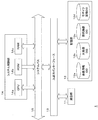
- FIG. 1 It is a figure which shows an example of schematic structure of the mosaic image provision system S which concerns on one Embodiment.
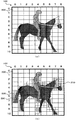
- (A) is a figure which shows the example of the original image 100 divided
- (b) is a figure which shows the example of the original image 100 by which the basic area containing an edge was divided
- (A) is a figure which shows the example of a display of the completed mosaic image 300a when it is assumed that a contribution image is allocated only with respect to a basic area
- (b) is a figure which the contribution image was allocated to the child area
- FIG. 1 It is a block diagram which shows an example of schematic structure of the mosaic image provision server 1 which concerns on one Embodiment.
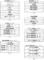
- A is a figure which shows an example of the content registered into member information DB12a which concerns on one Embodiment
- (b) is a figure which shows an example of the content registered into original image DB12b
- (c) Is a diagram showing an example of content set in basic area information
- (d) is a diagram showing an example of content registered in post image DB 12c
- (e) is set in post image information.
- F is a figure which shows an example of the content registered into mosaic image DB12d
- (g) is a figure which shows an example of the content set to allocation image information. is there.
- FIG.2 It is a figure which shows an example of the edge degree of each basic area
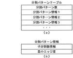
- (A) is a figure which shows an example of the content set to a division
- (b) is a figure which shows an example of the content set to division
- It is a flowchart which shows the process example in the original image registration process of the system control part 14 of the mosaic image provision server 1 which concerns on one Embodiment.
- FIG. 1 is a diagram illustrating an example of a schematic configuration of a mosaic image providing system S according to the present embodiment.
- the mosaic image providing system S includes a mosaic image providing server 1 and a plurality of user terminals 2.
- the mosaic image providing server 1 and each user terminal 2 can transmit / receive data to / from each other using, for example, TCP / IP as a communication protocol via the network NW.
- the network NW is constructed by, for example, the Internet, a dedicated communication line (for example, a CATV (Community Antenna Television) line), a mobile communication network (including a base station), a gateway, and the like.
- the mosaic image providing server 1 (an example of an image providing apparatus in the present invention) transmits a Web page on which a mosaic image that can be obtained by arranging (combining) a plurality of images serving as materials in a tile shape is displayed to the user terminal 2. Web server.
- the mosaic image providing server 1 acquires images from each user terminal 2 via the network NW in order to collect images that are materials.
- the image acquired from the user terminal 2 is an image posted by the user (hereinafter referred to as “posted image”).
- the user terminal 2 is a terminal device of a user who uses the mosaic image providing system S.
- the user terminal 2 accesses the mosaic image providing server 1 based on an operation from the user. Thereby, the user terminal 2 receives and displays the Web page from the mosaic image providing server 1.
- the user posts an image that is a material of a mosaic image or displays a mosaic image through a Web page displayed on the screen of the user terminal 2.
- Software such as a browser and an e-mail client is incorporated in the user terminal 2.
- the mosaic image providing system S having such a configuration, for example, an image that is a source of the pattern of the mosaic image is prepared in advance. This image is the original image.
- the mosaic image providing server 1 arranges the posted images so that the pattern represented by the mosaic image is close to the pattern represented by the original image.
- FIG. 2A and FIG. 2B are diagrams showing an example of the original image and an example of dividing the original image.
- An image 100 shown in FIGS. 2A and 2B is an image representing a pattern of a walking horse and a jockey riding on the horse.
- the color of the horse is dark brown.
- the color of the trousers of the jockey is yellow and the color of the jacket of the jockey is light blue.
- the background color is white. Note that each color is not filled with a uniform color, but changes in color to some extent depending on the location.
- the original image is divided into a plurality of areas (hereinafter referred to as “divided areas”).
- a posted image acquired from the user terminal 2 is assigned to each divided area.
- the mosaic image providing server 1 divides the original image into a preset number of divided regions.
- a divided area created when the original image is first divided is called a “basic area”.
- the image 100 is divided into 99 divided areas 200, which are 9 basic areas and 11 vertical areas.
- the number of divided areas is referred to as “divided number”.
- the total number of basic areas is referred to as “basic division number”.
- FIG. 3A is a diagram illustrating a display example of the completed mosaic image 300a when it is assumed that the posted image is assigned only to the basic region.
- a completed mosaic image is a mosaic image in which posted images are assigned to all divided regions.
- the ratio of the display area of each divided region 200 to the display area of the original image is relatively large. Therefore, if a mosaic image is generated in this state, a mosaic image having a relatively low resolution is generated as shown in FIG. Therefore, the visibility of the pattern of the original image is not high.
- the mosaic image providing server 1 further divides the basic region including the edge of the image into a plurality of divided regions (hereinafter referred to as “child regions”) so that the visibility of the pattern of the original image is increased.
- An edge refers to a portion where the brightness, hue, saturation, etc. of an image changes abruptly (sharply).
- the basic region including the edge may be, for example, a contour portion, a feature portion, a complicated pattern portion, or the like of the pattern of the original image.
- the mosaic image providing server 1 calculates the edge degree of each basic area as an index indicating the degree of the edge in order to identify the basic area including the edge. The higher the degree of change in the brightness or the like of the image included in the basic area, that is, the stronger the edge, the higher the edge degree of the basic area. Further, the greater the amount of edges included in the divided area, the higher the edge degree of the basic area. Then, the mosaic image providing server 1 determines a basic region whose edge degree is equal to or greater than a preset threshold as a basic region including an edge.
- the mosaic image providing server 1 increases the number of divisions as the basic region has a higher edge degree. That is, the mosaic image providing server 1 divides into more child areas. Therefore, the basic region having a higher edge degree is divided into smaller child regions. The number of divisions at this time is referred to as “number of child divisions”.
- a divided area 200 including an edge has a total of four divided areas 210, two horizontal and two vertical, three horizontal and three vertical depending on the degree of edge. It is divided into any of the nine divided regions 220 or any child region out of a total of 16 divided regions 230 of 4 horizontal and 4 vertical.
- the mosaic image providing server 1 assigns a posted image to a basic area for a basic area that is not divided into child areas.
- the mosaic image providing server 1 assigns a posted image to a child area created (generated) by dividing the basic area divided into child areas.
- FIG. 3B is a diagram showing a display example of the completed mosaic image 300b.
- FIG. 3B is a mosaic image generated by assigning a posted image to each divided region shown in FIG.
- the display area per one divided region in the edge portion is smaller than the display area per one divided region in the portion having no edge. Therefore, the resolution of the edge portion is increased, and the visibility of the edge can be improved.
- the visibility of the pattern of an original image can be improved by improving the visibility of an edge.
- the display area per division area becomes smaller as the edge degree is higher, the visibility of the pattern of the original image can be further improved.
- the number of divided areas 200 divided into four divided areas 210 is seventeen.
- the number of divided areas 200 divided into nine divided areas 220 is 24.
- the number of divided areas 200 divided into 16 divided areas 230 is four.
- the total number of divided areas is 402.
- the total number of divided regions is 496.
- the mosaic image providing server 1 does not divide the basic area having a small influence on the visibility of the design of the original image into the child areas, or reduces the number of child divisions even if divided. Thereby, by suppressing the total number of divided areas, it is possible to reduce the number of posted images necessary for completing the mosaic image and improve the visibility of the pattern of the original image.
- FIG. 4 is a block diagram illustrating an example of a schematic configuration of the mosaic image providing server 1 according to the present embodiment.
- the mosaic image providing server 1 includes a communication unit 11, a storage unit 12, an input / output interface 13, and a system control unit 14.
- the system control unit 14 and the input / output interface 13 are connected via a system bus 15.
- the communication unit 11 is connected to the network NW and controls the communication state with the user terminal 2 and the like.
- the storage unit 12 is composed of, for example, a hard disk drive.
- a member information DB (database) 12a an original image DB 12b, a posted image DB 12c, a mosaic image DB 12d, and the like are constructed.
- FIG. 5A is a diagram showing an example of contents registered in the member information DB 12a according to the present embodiment.
- member information related to users who are registered as members in the mosaic image providing system S is registered. Specifically, the user ID, password, nickname, name, date of birth, gender, address, telephone number, e-mail address, etc., which are user identification information, are registered in association with each user in the member information DB 12a.
- the user ID, password, nickname, name, date of birth, gender, address, telephone number, e-mail address, etc. which are user identification information, are registered in association with each user in the member information DB 12a.
- FIG. 5B is a diagram illustrating an example of contents registered in the original image DB 12b according to the present embodiment.
- the original image and information related to the original image are registered.
- an original image ID, original image data, basic division number information, and a plurality of basic area information, which are identification information of the original image are registered in association with each original image.
- the original image ID is identification information of the original image.
- the original image data is image data of the original image. Examples of the format of image data used in the mosaic image providing system S include JPEG (Joint Photographic Experts Group), TIFF (Tagged-Image File Format), PNG (Portable Network Graphics), and the like.
- the basic division number information is information indicating the basic division number.
- the basic division number information includes a basic division number, a basic horizontal division number, and a basic vertical division number.
- the basic horizontal division number is the horizontal division number. That is, the basic horizontal division number is the number of basic regions arranged in the horizontal direction of the original image.
- the basic vertical division number is the vertical division number. That is, the basic vertical division number is the number of basic regions arranged in the vertical direction of the original image.
- the basic division number is obtained by multiplying the basic horizontal division number and the basic vertical division number.
- the basic area information is information related to the basic area.
- Basic area information is registered for the number of basic divisions. Each basic area information is registered in association with the index of the corresponding basic area.
- Each basic area is assigned an index in the form of (X1, Y1).
- X1 indicates the position of the basic region in the horizontal direction.
- Y1 indicates the position of the basic region in the vertical direction.
- the index of the basic area located at the upper left corner of the original image is (0, 0).
- the basic area (X1, Y1) is a basic area located Y1 + 1 from the top among the basic areas located X1 + 1 from the leftmost.
- dividing the original image into a plurality of areas means dividing an area corresponding to the entire original image into a plurality of areas, and in which area each pixel in the original image is included ( Alternatively, it is possible to specify which pixels each region includes).
- the system control unit 14 can specify a region including each pixel by acquiring the number of vertical and horizontal pixels, the number of horizontal divisions, and the number of vertical divisions of the original image. Therefore, dividing the original image into a plurality of regions does not necessarily mean dividing the image data of the original image into image data for each region. Therefore, the system control unit 14 may or may not register the image data for each area in the original image DB 12b.
- FIG. 5C is a diagram showing an example of contents set in the basic area information. As shown in FIG. 5C, the basic area information is set with an edge degree, child division number information, and one or more representative color values.
- the edge degree is used to determine whether or not to divide the basic region and to determine the number of child divisions when dividing.
- the edge degree is calculated by the system control unit 14.
- the system control unit 14 calculates the pixel edge degree of each pixel included in the basic region.
- the pixel edge degree indicates the strength of the edge of the pixel itself.
- the system control unit 14 calculates the difference between the value of the target pixel (the pixel for which the pixel edge degree is calculated) and the value of each pixel adjacent to the target pixel.
- the pixel value exists for each basic color (primary color) of R (red), G (green), and B (blue), for example.
- Each pixel value of R, G, and B takes any value from 0 to 255, for example.
- the system control unit 14 performs this calculation for each basic color.
- the pixels adjacent to the target pixel are eight pixels located in the up / down / left / right and diagonal directions of the target pixel. Then, the system control unit 14 adds the differences calculated for each basic color, and further adds the differences for 8 pixels to calculate the pixel edge degree.
- equations the following equation 1 is obtained.
- Equation 1 x is the X coordinate of the pixel of interest based on the pixel in the upper left corner of the region of interest (the basic region for which the edge degree is calculated), and y is in the upper left corner of the region of interest. This is the Y coordinate of the target pixel based on the pixel.
- R (x, y), G (x, y), and B (x, y) are the R pixel value, G pixel value, and B pixel value of the pixel at coordinates (x, y).
- EP (x, y) is the pixel edge degree of the pixel at the coordinates (x, y).
- the pixel value may be expressed in, for example, CMYK, Lab color space, or the like.
- the system control unit 14 calculates the square of the difference calculated for each basic color instead of taking the absolute value of the difference calculated for each basic color and adding the absolute values, and calculates the calculation result. You can add them together.
- the system control unit 14 adds the pixel edge degrees of all the pixels in the basic area, and calculates the edge degree of the basic area. This process is expressed by the following formula 2.
- EB (X1, Y1) is the edge degree of the basic region (X1, Y1). Further, w is the number of pixels in the horizontal direction of the basic region, and l is the number of pixels in the vertical direction of the basic region.
- the edge degree calculation method is not limited to the method described here. For example, when calculating the pixel edge degree, the system control unit 14 may calculate a difference in pixel values for only four pixels located above, below, left, and right of the target pixel. In addition, the system control unit 14 does not calculate the difference between the pixel values for each basic color, but calculates the distance between the color of the pixel of interest and the color of the adjacent pixel, for example, and adds the color distances Then, the pixel edge degree may be calculated.
- FIG. 6 is a diagram showing an example of the edge degree of each basic region 200 shown in FIG. FIG. 6 shows the normalized edge degree so that the difference in edge degree of each basic region can be easily understood.
- the edge degree of the basic region including no edge is zero.
- the edge degree of the basic region including the outline of the horse and the outline of the jockey increases with the length of the outline.
- the edge degree is high in the contour portion of a horse having a large difference in brightness from the background.
- the tail part of a horse with many lines for example, basic areas (0, 6), (0, 7)
- the hand part of a jockey with a complicated pattern for example, basic areas (4, 3)
- the degree is getting higher.
- Child division number information is information indicating the number of child divisions of the basic area (X1, Y1). Specifically, the child division number information includes a child division number, a child horizontal division number, and a child vertical division number.
- the child horizontal division number is the number of horizontal divisions. That is, the child horizontal division number is the number of child regions arranged in the horizontal direction of the basic region.
- the child vertical division number is the number of vertical divisions. That is, the child vertical division number is the number of child regions arranged in the vertical direction of the basic region.
- the child division number is obtained by multiplying the child horizontal division number and the child vertical division number.
- 1 is set for all of the child division number, child horizontal division number, and child vertical division number of the child division number information.
- the representative color value is a value indicating a color representing the divided area (hereinafter referred to as “representative color”).
- the representative color may be a color obtained by averaging the colors of the entire divided area, or may be a color having the largest exclusive area in the divided area.
- the representative color value includes, for example, a value for each basic color of R, G, and B.
- the system control unit 14 determines candidate divided areas to which the posted image is assigned by comparing the representative color value of the divided area with the representative color value of the posted image.
- the representative color value may be expressed in, for example, CMYK, Lab color space, or the like.
- the representative color values are registered for the number of child divisions included in the child division number information. Each representative color value is registered in association with the index of the corresponding basic area and child area.
- Each child area is assigned an index in the form of (X1, Y1) (X2, Y2).
- X1 and Y1 are indices of basic areas including child areas.
- X2 indicates the position of the child region in the horizontal direction in the basic region (X1, Y1).
- Y2 indicates the position of the child area in the vertical direction in the basic area (X1, Y1).
- the index of the child area located at the upper left corner of the basic area (X1, Y1) is (X1, Y1) (0, 0).
- the child area (X1, Y1) (X2, Y2) is the child area located at the (Y2 + 1) th position from the top among the child areas located at the X2 + 1th position from the leftmost of the basic area (X1, Y1).
- the basic area is not divided.
- the representative color value (X1, Y1) (0, 0) is registered as the representative color value in the basic area information (X1, Y1).
- the representative color value (X1, Y1) (0, 0) in this case is the representative color value of the basic area (X1, Y2).
- the representative color values (X1, Y1) (Y2, Y2) are the representative color values of the child regions (X1, Y1) (Y2, Y2).
- FIG. 5D is a diagram illustrating an example of contents registered in the posted image DB 12c according to the present embodiment.
- the posted image and information related to the posted image are registered in the posted image DB 12c.
- the mosaic image ID, the number of posts, and post image information are registered in the post image DB 12c.
- the mosaic image ID is identification information of a mosaic image generated using a registered posted image as a material.
- the number of posts is the number of posted images acquired from the user terminal 2 so far.
- Post image information is registered for the number of posts.
- FIG. 5E is a diagram showing an example of contents set in the posted image information.
- post image information is set in association with an image number, a user ID, post image data, and a representative color value.
- the image number is a number assigned to the posted image.
- Each posted image is given an image number in the order of posting (the order acquired by the mosaic image providing server 1).
- the user ID set in the posted image information is the user ID of the user who posted the posted image. That is, the user ID set in the posted image information is the user ID of the user who uses the user terminal 2 from which the posted image is acquired.
- the posted image data is image data of a posted image.
- the representative color value is a value indicating the representative color of the posted image. Note that the content of the representative color value of the posted image is the same as the content of the representative color value of the divided area.
- FIG. 5F is a diagram illustrating an example of contents registered in the mosaic image DB 12d according to the present embodiment.
- Information related to the mosaic image is registered in the mosaic image DB 12d.
- a mosaic image ID is identification information of the mosaic image.
- the original image ID is an original image ID of an image that becomes a pattern of the mosaic image.
- the assigned image information is information indicating a posted image assigned to the divided area.
- the allocated image information is registered for the number of basic divisions of the original image. Each assigned image information is registered in association with the index of the corresponding basic area.
- FIG. 5G is a diagram illustrating an example of contents set in the allocation image information.
- one or more assigned image numbers are set in the assigned image information.
- the assigned image number is the image number of the posted image assigned to the divided area.
- an invalid number such as ⁇ 1 is set as the assigned image number of a divided region to which a posted image is not yet assigned (hereinafter referred to as “unassigned region”).
- the allocated image information (X1, Y1) includes the number of child divisions included in the child division number information of the basic area information (X1, Y1) registered in the original image DB 12b in association with the original image ID.
- the assigned image number is registered. Each assigned image number is registered in association with the index of the corresponding basic area and child area.
- the assigned image number (X1, Y1) (0, 0) is registered as the assigned image number in the assigned image information (X1, Y1).
- the assigned image number (X1, Y1) (0, 0) is the image number of the posted image assigned to the basic area (X1, Y1).
- the assigned image number (X1, Y1) (Y2, Y2) is the image number of the posted image assigned to the child area (X1, Y1) (Y2, Y2).
- Mosaic image display data is data for displaying a mosaic image in a Web page. That is, the mosaic image display data indicates the display content of the mosaic image.
- the mosaic image is expressed as a table in which the posted image is inserted in each cell.
- the mosaic image display data is data described in a markup language such as HTML (Hyper Text Markup Language), XML (Extensible Markup Language), or XHTML (Extensible Text Text Markup Language).
- the mosaic image display data constitutes a part of the HTML document of the Web page on which the mosaic image is displayed.
- the system control unit 14 causes the user terminal 2 to display a mosaic image based on the HTML document by transmitting an HTML document including the mosaic image display data to the user terminal 2.
- the user terminal 2 displays the posted image in each cell of the table according to the description content of the mosaic image display data included in the HTML document, thereby displaying the mosaic image in the Web page.
- the user terminal 2 generates (forms) a mosaic image on the screen.
- “http: //www.yyy.zzz/9876543210-0123.jpeg” is a URL (Uniform Resource Locator) of posted image data.
- “9876543210” is the original image ID.
- “0123” is the image number of the posted image.
- an img tag including the URL of the assigned posted image is set in the cell corresponding to the divided area to which the posted image is assigned.
- This URL may be the URL of the thumbnail image data of the posted image.
- the posted image is usually displayed in a size smaller than the original display size. Therefore, thumbnail image data obtained by reducing the display size by reducing the number of vertical and horizontal pixels of the posted image may be transmitted to the user terminal 2 that intends to display the mosaic image.
- the system control unit 14 when the posted image data is registered in the posted image DB 12c, the system control unit 14 generates thumbnail image data of the posted image based on the posted image data, and the thumbnail image data is stored in the posted image DB 12c. sign up.
- the system control unit 14 may generate mosaic image display data based on the assigned image information when transmitting a Web page on which the mosaic image is displayed.
- the storage unit 12 stores a division pattern table.
- FIG. 7A is a diagram illustrating an example of contents set in the division pattern table.
- the division pattern table is table information indicating the correspondence between the edge degree of the basic area and the number of child divisions. As shown in FIG. 7A, the number of division patterns and one or more pieces of division pattern information are set in the division pattern table.
- the division pattern number indicates the number of child division number patterns.
- the number of division patterns is 3.
- the division pattern information is set for the number of division patterns.
- FIG. 7B is a diagram illustrating an example of contents set in the division pattern information. As shown in FIG. 7B, the division pattern information is set with the child division number information and the minimum edge degree. The content of the child division number information set in the division pattern information is the same as the content of the child division number information registered in the original image DB 12b.
- the minimum edge degree is the minimum value of the edge degree necessary for dividing the basic region by the number of child divisions included in the child division number information.
- N is an integer of 1 or more
- Each division pattern information is set so that the edge degree of the division pattern information N + 1> the edge degree of the division pattern information N.
- the number of child divisions, the number of child horizontal divisions, the number of child vertical divisions and the minimum edge degree (an example of preset values in the present invention) of the division pattern information 1 are, for example, 4 2, 2, and 3.
- the division pattern information 2 is 9, 3, 3, 7 for example.
- the division pattern information 3 is 16, 4, 4, 20, for example.
- the content of the child division number information when the basic region is divided matches the content of the child division number information included in any of the division pattern information. .
- the number of division patterns and each piece of division pattern information are performed by, for example, an administrator of the mosaic image providing server 1.
- the number of division patterns may be one or more. Further, the number of child horizontal divisions and the number of child vertical divisions may not be the same. Further, as long as the condition of the above equation is satisfied, the child division number information and the minimum edge degree can be arbitrarily set. For example, when the number of division patterns is 1, all basic areas whose edge degrees are equal to or higher than the minimum edge degree included in the division pattern information 1 are divided into the same number of child areas. In addition, when the number of division patterns is two or more, a basic region with a higher edge degree is divided into more child regions.
- the storage unit 12 stores various data such as an HTML document, an XML document, image data, text data, and an electronic document for displaying a Web page.
- the storage unit 12 stores various setting values set by an administrator or the like.
- the setting value includes a threshold value for determining whether the color of the posted image is close to the color of the divided area.
- the storage unit 12 stores various programs such as an operating system, a WWW (World Wide Web) server program, a DBMS (Data Base Management System), and a mosaic image providing program.
- the mosaic image providing program is a program for executing processing related to a mosaic image such as registration of an original image, acquisition of a posted image, generation of mosaic image display data, and the like.
- the various programs may be acquired from other server devices or the like via the network NW, or may be recorded on a recording medium such as a DVD (Digital Versatile Disc) and read via the drive device. You may do it.
- the input / output interface 13 performs interface processing between the communication unit 11 and the storage unit 12 and the system control unit 14.
- the system control unit 14 includes a CPU 14a, a ROM (Read Only Memory) 14b, a RAM (Random Access Memory) 14c, and the like.
- the system control unit 14 functions as a specifying unit, a dividing unit, an acquiring unit, a determining unit, and a presenting unit in the present invention by the CPU 14a reading and executing various programs.
- the mosaic image providing server 1 may be configured by a plurality of server devices.
- a server device that performs processing related to registration of original images, acquisition of posted images, and generation of mosaic image display data
- a server device that transmits a Web page in response to a request from the user terminal 2 a server device that manages a database, and the like
- they may be connected to each other via a LAN or the like.
- FIG. 8 is a flowchart showing a processing example in the original image registration processing of the system control unit 14 of the mosaic image providing server 1 according to the present embodiment.
- the administrator of the mosaic image providing server 1 registers the original image by operating the management terminal device connected to the mosaic image providing server 1. Specifically, the administrator selects the original image data and inputs the basic horizontal division number and the basic vertical division number. Then, the management terminal device transmits an original image registration request including the original image data, the basic horizontal division number, and the basic vertical division number to the mosaic image providing server 1. For example, the user may be able to post the original image. In this case, the user terminal 2 of the user who posts the original image transmits an original image registration request.
- the original image registration process is started when the mosaic image providing server 1 receives an original image registration request. This original image registration process is executed in advance before a post image reception process described later. Then, by executing the original image registration process, it is possible to assign a post image in the post image reception process.
- the system control unit 14 In the original image registration process, the system control unit 14 generates a new original image ID. Next, the system control unit 14 generates basic division number information based on the basic horizontal division number and the basic vertical division number included in the received original image registration request. Then, the system control unit 14 associates the new original image ID, the original image data included in the original image registration request, and the basic division number information each time it is generated, and registers them in the original image DB 12b (step S11).
- the system control unit 14 generates a new mosaic image ID.
- the system control unit 14 associates the new mosaic image ID with the original image ID and registers them in the mosaic image DB 12d (step S12). Further, the system control unit 14 develops a bitmap image of the original image in the RAM 14c based on the original image data.
- the system control unit 14 divides the original image into a plurality of basic areas.
- the system control unit 14 sets 0 to the index Y1 of the basic area (step S13).
- the system control unit 14 sets 0 to the index X1 of the basic area (step S14).
- the system control unit 14 specifies the basic area (X1, Y1) (step S15). Specifically, the system control unit 14 acquires the number of vertical and horizontal pixels of the original image from the registered original image data.
- the system control unit 14 determines the basic area (X1, X1) based on the number of vertical and horizontal pixels of the original image, the basic horizontal division number and the basic vertical division number indicated by the registered basic division number information, and the indexes X1 and Y1. The coordinate range of the pixel included in Y1) is calculated.
- the system control unit 14 calculates the pixel edge degree of each pixel included in the divided area (X1, Y1) (step S16). Specifically, the system control unit 14 acquires the value of each pixel included in the divided area (X1, Y1) from the bitmap image of the original image developed in the RAM 14c. Then, the system control unit 14 calculates the pixel edge degree by, for example, a calculation method represented by Expression 1.
- the system control unit 14 calculates the edge degrees of the divided regions (X1, Y1) based on the calculated pixel edge degrees. For example, the system control unit 14 calculates the edge degree by the calculation method represented by Equation 2. Then, the system control unit 14 registers the calculated edge degree in the original image DB 12b in association with the new original image ID and the indexes X1 and Y1 (step S17).
- the system control unit 14 associates the child division number information of the basic area (X1, Y1) with the new original image ID and the indexes X1 and Y1 based on the calculated edge degree and the division pattern table. Are registered in the original image DB 12b (step S18). Specifically, the system control unit 14 compares the minimum edge degree included in the division pattern information with the calculated edge degree in ascending order of the index value of the division pattern information. Here, when the calculated edge degree is smaller than the minimum edge degree included in the division pattern information 1, the system control unit 14 has all the child division number, the child horizontal division number, and the child vertical division number being 1. Register child division number information.
- the system control unit 14 registers the child division number information included in the division pattern information.
- the system control unit 14 specifies the basic region including the edge as the specifying unit.
- the system control unit 14 registers the assigned image information (X1, Y1) in the mosaic image DB 12d in association with the new mosaic image ID and the indexes X1 and Y1 (step S19). At this time, the system control unit 14 makes the number of assigned image numbers included in the assigned image information (X1, Y1) the same as the number of child divisions included in the registered child division number information. Further, the system control unit 14 sets an invalid number indicating an unallocated area for each allocated image number.
- the system control unit 14 sets 0 to the index Y2 of the child area (step S20).
- the system control unit 14 sets 0 to the index X2 of the child area (step S21).
- the system control unit 14 specifies divided areas (X1, Y1) (X2, Y2) (step S22). Specifically, the system control unit 14 determines the number of vertical and horizontal pixels of the original image, the basic horizontal division number and the basic vertical division number included in the registered basic division number information, and the child horizontal number included in the registered child division number information.
- the coordinate range of the pixels included in the divided regions (X1, Y1) (X2, Y2) is calculated.
- the region (X1, Y1) (X2, Y2) is a child region.
- the system control unit 14 calculates representative color values of the divided areas (X1, Y1) (X2, Y2) (step S23). For example, the system control unit 14 acquires the values of the pixels included in the divided areas (X1, Y1) (X2, Y2) from the bitmap image of the original image developed in the RAM 14c. Next, the system control unit 14 adds the acquired pixel values for each of the R, G, and B basic colors. Next, the system control unit 14 divides the sum of the pixel values for each basic color by the total number of pixels included in each of the divided regions (X1, Y1) (X2, Y2). The average of the pixel values for each basic color obtained by this calculation is the representative color value. Next, the system control unit 14 registers the calculated representative color value in the original image DB 12b in association with the new original image ID and the indexes X1, Y1, X2, and Y2.
- step S24 the system control unit 14 adds 1 to the index X2 (step S24).
- step S25 the system control unit 14 determines whether or not the index X2 is less than the child horizontal division number (step S25). At this time, if the system control unit 14 determines that the index X2 is less than the child horizontal division number (step S25: YES), the system control unit 14 proceeds to step S22. On the other hand, when the system control unit 14 determines that the index X2 is not less than the child horizontal division number (step S25: NO), the system control unit 14 adds 1 to the index Y2 (step S26). Next, the system control unit 14 determines whether or not the index Y2 is less than the number of child vertical divisions (step S27).
- step S27 if the system control unit 14 determines that the index Y2 is less than the number of child vertical divisions (step S27: YES), the system control unit 14 proceeds to step S21.
- the system control unit 14 registers the representative color values of the basic area (X1, Y1) or the representative color values of the child areas included in the basic area (X1, Y1) by repeating the processes of steps S21 to S27. .
- the edge degree of the basic area is equal to or higher than the minimum edge degree included in the division pattern information 1
- the system control unit 14 divides the basic area into a plurality of child areas as a dividing unit.
- step S27: NO the system control unit 14 adds 1 to the index X1 (step S28).
- step S29 the system control unit 14 determines whether the index X1 is less than the basic horizontal division number. At this time, if the system control unit 14 determines that the index X1 is less than the basic horizontal division number (step S29: YES), the system control unit 14 proceeds to step S15. On the other hand, when the system control unit 14 determines that the index X1 is not less than the basic horizontal division number (step S29: NO), the system control unit 14 adds 1 to the index Y1 (step S30).
- step S31 determines whether the index Y1 is less than the basic vertical division number. At this time, if the system control unit 14 determines that the index Y1 is less than the basic vertical division number (step S31: YES), the system control unit 14 proceeds to step S14.
- the system control unit 14 registers the representative color values of all the divided areas by repeating the processes of steps S14 to S31.
- the system control unit 14 determines that the index Y1 is not less than the basic vertical division number (step S31: NO), the system control unit 14 generates empty mosaic image display data, and the generated mosaic image display data is newly set. Is registered in the mosaic image DB 12d in association with a unique mosaic image ID (step S32).
- the empty mosaic image display data is mosaic image display data in which no img tag including the URL of the posted image data is set.
- the system control unit 14 performs child horizontal division for cells corresponding to the basic region divided into child regions.
- Mosaic image display data is generated so as to be further divided into a plurality of cells according to the number and the number of child vertical divisions.
- the system control unit 14 generates an HTML document of the image posting / mosaic image display page 400 (step S33).
- the image posting / mosaic image display page 400 is a Web page for posting an image and also a Web page on which a mosaic image is displayed.
- the system control unit 14 stores the generated HTML document in the storage unit 12.
- the system control unit 14 sets a hyperlink to the generated HTML document (step S34). For example, the system control unit 14 adds an a tag including the URL of the HTML document of the image posting / mosaic image display page 400 to the HTML document of the top page of the website of the mosaic image providing system S. Thereby, the user can post images and browse mosaic images.
- the system control unit 14 ends the original image registration process.
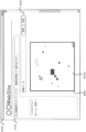
- FIG. 9 is a diagram showing a screen display example of the image posting / mosaic image display page 400 according to the present embodiment.
- the image posting / mosaic image display page 400 includes a message unit 410, a posted image transmission unit 420, a mosaic image display unit 430, and the like.
- the message unit 410 for example, information such as notifications regarding products and services on a site related to the mosaic image providing system S is displayed.
- the posted image transmission unit 420 displays various widgets (operation elements) for posting images. For example, an input field for designating a path name of posted image data, a reference button for displaying a dialog for selecting posted image data from the image data stored in the user terminal 2, and a posted image data A transmission button or the like for transmission is displayed.
- a mosaic image generated by the images posted so far is displayed.
- a mosaic image 300c is displayed as an example of the mosaic image.
- the mosaic image 300c is a mosaic image generated by assigning a posted image to a part of the divided areas shown in FIG. If no image has been posted yet after the original image registration process is completed, the mosaic image is not displayed on the mosaic image display unit 430.
- the system control unit 14 sets the user ID of the user who posted the posted image in the mosaic image display data.
- the user terminal 2 transmits a request including the user ID of the user who posted the posted image to the mosaic image providing server 1.
- the system control unit 14 acquires necessary information from the member information corresponding to the user ID included in the received request and transmits it to the user terminal 2. Then, the user terminal 2 displays the received information.
- FIG. 10 is a flowchart showing a processing example in the posted image reception process of the system control unit 14 of the mosaic image providing server 1 according to the present embodiment.
- the posted image transmission unit 420 of the image posting / mosaic image display page 400 when the user specifies posted image data and selects a transmission button, the user terminal 2 transmits a posting request to the mosaic image providing server 1.
- the posting request includes the specified posting image data, the user ID of the user who performed the operation, and the mosaic image ID of the mosaic image to be generated.
- the post image receiving process is started when the mosaic image providing server 1 receives a post request as an acquisition unit.
- the system control unit 14 determines a divided area to which the posted image is allocated as a determination unit by the processing of steps S51 to S56. First, the system control unit 14 calculates a representative color value of a posted image (hereinafter referred to as “processed posted image”) indicated by posted image data included in the posted request (step S51). This calculation method is the same as that in step S23 in the original image registration process.
- the system control unit 14 performs exclusive control using, for example, a mutex, and performs a lock operation when acquiring the authority to execute the processing (critical session) after step S52. Thereby, the system control unit 14 prevents a plurality of processes from executing critical sessions simultaneously.
- the system control unit 14 initializes the assignment candidate list and sets it in the RAM 14c (step S52).
- the assignment candidate list is a list of divided areas (hereinafter referred to as “candidate areas”) that satisfy the conditions for assigning the processing target posted image.
- the candidate area refers to a divided area where the difference in representative color value from the processing target posted image is equal to or less than a threshold value.
- X1, Y1, X2, and Y2 that are indexes of candidate areas and the difference value of the representative color value from the processing target posted image are registered in association with each other.
- step S53 the system control unit 14 executes a candidate area search process described later (step S53).
- candidate areas are searched from unallocated areas, and the searched candidate areas are registered in the allocation candidate list.
- the system control unit 14 determines whether or not a candidate area has been searched (step S54). Specifically, the system control unit 14 determines whether or not one or more sets of candidate region indexes and difference values are registered in the allocation candidate list. At this time, if the index and the difference value of the candidate area are not registered in the allocation candidate list, the system control unit 14 determines that the candidate area could not be searched (step S54: NO). In this case, the system control unit 14 transmits a posting rejection message to the user terminal 2 that has transmitted the posting request (step S55). The posting rejection message is a message indicating that image posting has been rejected. The user terminal 2 displays the received post rejection message on the screen. When completing the process of step S55, the system control unit 14 ends the posted image reception process.
- the system control unit 14 determines that the candidate area can be searched (step S54: YES). In this case, the system control unit 14 assigns a candidate area having the smallest difference in representative color value from the processing target posted image among the searched candidate areas to a divided area (hereinafter, “allocation target area” to which the processing target posted image is assigned. ”) (Step S56). Specifically, the system control unit 14 searches for the smallest value from the difference values registered in the assignment candidate list. Then, the system control unit 14 acquires the indexes X1, X2, Y1, and Y2 associated with the smallest difference value from the allocation candidate list as the allocation target area index.
- the system control unit 14 adds 1 to the number of posts registered in the posted image DB 12c in association with the mosaic image ID (hereinafter referred to as “target mosaic image ID”) included in the posting request, and calculates the number of posts. Update (step S57).
- the system control unit 14 sets the updated number of posts in the image number of the processing target posted image (step S58).
- the system control unit 14 associates post image information including the image number, the user ID and post image data included in the post request, and the representative color value of the processing target post image with the target mosaic image ID, and the post image DB 12c. (Step S59).
- the system control unit 14 rewrites the allocation image number of the allocation target area registered in the mosaic image DB 12d in association with the target mosaic image ID to the image number of the processing target posted image (step S60).
- the system control unit 14 updates the mosaic image display data registered in the mosaic image DB 12d in association with the target mosaic image ID (step S61). Specifically, the system control unit 14 sets an img tag including the URL of the posted image data of the processing target posted image in a cell corresponding to the index of the allocation target region in the mosaic image display data.
- the system control unit 14 generates an HTML document of the image posting / mosaic image display page 400 including the updated mosaic image display data, and stores the HTML document in the storage unit 12 (step S62).
- the system control unit 14 transmits the generated HTML document to the user terminal 2 that has transmitted the posting request (step S63).
- the system control unit 14 performs an unlock operation so that another process can execute the critical session.
- the system control unit 14 ends the posted image reception process.
- the user terminal 2 displays the image posting / mosaic image display page 400 on the screen based on the received HTML document.
- the system control unit 14 transmits a request including the URL of the posted image data to the mosaic image providing server 1 based on the img tag included in the mosaic image display data.
- the system control unit 14 acquires the mosaic image ID and the image number from the URL included in the received request.
- the system control unit 14 acquires posted image data corresponding to the acquired mosaic image ID and image number from the posted image DB 12c.
- the system control unit 14 transmits the acquired posted image data to the user terminal 2.
- the user terminal 2 displays the posted image in the mosaic image display unit 430 of the image posting / mosaic image display page 400 based on the acquired posted image data. Thereby, for example, a mosaic image as shown in FIG. 9 is displayed.
- the system control unit 14 causes the user terminal 2 to present a mosaic image as a presentation unit by transmitting the mosaic image display data.
- FIG. 11 is a flowchart illustrating a processing example in the candidate area search process of the system control unit 14 of the mosaic image providing server 1 according to the present embodiment.
- the system control unit 14 acquires an original image ID (hereinafter referred to as “target original image ID”) corresponding to the target mosaic image ID from the mosaic image DB 12d.
- the system control unit 14 acquires basic division number information corresponding to the target original image ID from the original image DB 12b (step S101).
- the system control unit 14 sets 0 to the index Y1 of the basic area (step S102).
- the system control unit 14 sets 0 to the index X1 of the basic area (step S103).
- the system control unit 14 acquires child division number information from the basic area information (X1, Y1) registered in the original image DB 12b in association with the target original image ID (step S104).
- the system control unit 14 sets 0 to the index Y2 of the child area (step S105).
- the system control unit 14 sets 0 to the child area index X2 (step S106).
- the system control unit 14 determines whether or not the divided areas (X1, Y1) (X2, Y2) are unallocated areas (step S107). Specifically, the system control unit 14 determines whether the assigned image number (X1, Y1) (X2, Y2) registered in the mosaic image DB 12d in association with the target mosaic image ID is a number indicating an unassigned area. Determine whether.
- the system control unit 14 determines with it being an area
- Equation 3 Diff is the difference.
- R1, G1, and B1 are representative color values of R, G, and B in the divided areas (X1, Y1) (X2, Y2).
- R2, G2, and B2 are the representative color values of R, G, and B of the processing target posted image.
- the system control unit 14 calculates the square of the difference calculated for each basic color, and instead of adding the calculation results, takes the absolute value of the difference calculated for each basic color, and calculates the absolute value. You may add them together.
- step S109 determines whether or not the calculated difference value is equal to or less than a threshold value.
- step S109: YES the system control unit 14 determines the divided regions (X1, Y1) (X2, Y2) as candidate regions (steps). S110). Specifically, the system control unit 14 associates the indexes X1, Y1, X2, and Y2 with the calculated difference values and registers them in the assignment candidate list. Then, the system control unit 14 proceeds to step S111.
- step S107 if the assigned image number (X1, Y1) (X2, Y2) is not a number indicating an unassigned area, the system control unit 14 has not assigned the divided area (X1, Y1) (X2, Y2). It determines with it not being an allocation area
- step S109 when the system control unit 14 determines that the difference value is not equal to or less than the threshold value (step S109: NO), the system control unit 14 proceeds to step S111.
- step S111 the system control unit 14 adds 1 to the index X2.
- step S112 determines whether or not the index X2 is less than the number of child horizontal divisions included in the acquired child division number information (step S112). At this time, if the system control unit 14 determines that the index X2 is less than the child horizontal division number (step S112: YES), the system control unit 14 proceeds to step S107. On the other hand, when the system control unit 14 determines that the index X2 is not less than the child horizontal division number (step S112: NO), the system control unit 14 adds 1 to the index Y2 (step S113).
- the system control unit 14 determines whether or not the index Y2 is less than the number of child vertical divisions included in the acquired child division number information (step S114). At this time, if the system control unit 14 determines that the index Y2 is less than the number of child vertical divisions (step S114: YES), the system control unit 14 proceeds to step S106.
- the system control unit 14 searches for candidate regions from the child regions included in the basic region (X1, Y1) or the basic region (X1, Y1) by repeating the processing of steps S106 to S114.
- step S114 When the system control unit 14 determines that the index Y2 is not less than the number of child vertical divisions (step S114: NO), the system control unit 14 adds 1 to the index X1 (step S115). Next, the system control unit 14 determines whether or not the index X1 is less than the basic horizontal division number included in the acquired basic division number information (step S116). At this time, if the system control unit 14 determines that the index X1 is less than the basic horizontal division number (step S116: YES), the system control unit 14 proceeds to step S104. On the other hand, when the system control unit 14 determines that the index X1 is not less than the basic horizontal division number (step S116: NO), the system control unit 14 adds 1 to the index Y1 (step S117).
- step S118 determines whether or not the index Y1 is less than the basic vertical division number included in the acquired basic division number information. At this time, if the system control unit 14 determines that the index Y1 is less than the basic vertical division number (step S118: YES), the system control unit 14 proceeds to step S103.
- the system control unit 14 searches for candidate areas from all unassigned by repeating the processing of steps S103 to S118.
- step S118 NO
- the system control unit 14 determines that the index Y1 is not less than the basic vertical division number
- the system control unit 14 of the mosaic image providing server 1 specifies an area including an image edge from a plurality of basic areas, and further specifies a plurality of specified basic areas. Area that allocates the posted image from among the basic area that is not divided into child areas and the child area created by the division. And a mosaic image in which the acquired posted images are arranged is presented to the user based on the determined assignment.
- the basic area including an edge that contributes to improving the visibility of the original image among the plurality of basic areas is divided into smaller child areas, so that the number of the divided areas necessary for completing the mosaic image is reduced and the original image is reduced. It is possible to provide a mosaic image with high visibility of the pattern.
- the system control unit 14 calculates an edge degree indicating the degree of edge included in the image of the basic area, and specifies an area where the edge degree is equal to or greater than a preset threshold as a basic area including the edge.
- an area including an edge can be determined by a preset value.
- system control unit 14 divides the identified basic region so that the basic region having a higher calculated edge degree has a larger number of divisions.
- the mosaic image providing server 1 calculates the difference in representative color value from the posted image for all the divided areas to which the posted image is not assigned.
- the system control unit 14 displays a list indicating divided areas in ascending order of R representative color values, a list indicating divided areas in ascending order of G representative color values, and a list indicating divided areas in ascending order of B representative color values.
- the system control unit 14 When the system control unit 14 receives the posted image data and calculates the representative value of the posted image, the system control unit 14 sets the minimum value and the maximum value of the representative value that have a difference from the representative value of the posted image equal to or less than the threshold value as R, G, Calculate for each B.
- the threshold value at this time may be different from the threshold value used when the difference is calculated by Equation 3.
- the system control unit 14 specifies, by using the generated list, a range of divided areas in which the difference between the representative value and the representative value of the posted image is equal to or less than a threshold value by, for example, a binary search method.
- the system control unit 14 executes this for R, G, and B.
- the system control unit 14 sets, as candidate areas, divided areas in which the difference in representative value from the posted image is equal to or less than the threshold in all of R, G, and B.
- the mosaic image providing server 1 determines a candidate area to which the posted image is allocated from among the unallocated areas. However, the mosaic image providing server 1 may determine a candidate area to which the posted image is assigned regardless of whether the posted image has already been assigned. For example, if the color of the processing target posted image to be assigned is closer to the color of the divided region than the color of the posted image already assigned to the divided region, the mosaic image providing server 1 May be assigned to the divided area, and the posted image assigned to the divided area may be assigned to the unallocated area.
- the mosaic image providing server 1 has determined the divided area having the smallest difference in representative color value from the posted image as the allocation target area. For example, the difference in the representative color value from the posted image. Any divided area may be determined as the allocation target area from among the divided areas having a threshold value equal to or less than the threshold value.
- the mosaic image providing server 1 assigns each posted image to one divided area, but may assign it to a plurality of areas, for example.
- the mosaic image providing server 1 may assign the same posted image to a plurality of areas from among the divided areas in which the difference in the representative color value from the posted image is equal to or less than the threshold value.
- the mosaic image providing server 1 has determined the allocation target area based on the representative color value of the posted image and the representative color value of the divided area.
- the allocation target area may be determined based on the pattern included in the divided area. For example, the mosaic image providing server 1 calculates the degree of coincidence indicating the coincidence between the pattern of the posted image and the pattern included in the divided region, and assigns an assignment target from among the divided regions where the degree of coincidence is equal to or greater than a preset threshold. An area may be determined. Further, for example, the mosaic image providing server 1 calculates the degree of coincidence of the image itself including the pattern and the color between the posted image and the divided area, and the divided area where the degree of coincidence is equal to or higher than a preset threshold value.
- the allocation target area may be determined from the inside.
- the mosaic image providing server 1 transmits an HTML document including mosaic image display data to the user terminal 2 in order to display the mosaic image on the user terminal 2.
- the mosaic image providing server 1 may transmit the image data of the mosaic image itself to the user terminal 2.
- the mosaic image providing server 1 is assigned based on, for example, the posted image data acquired so far and registered in the posted image DB 12c, and the assigned image number registered in the mosaic image DB 12d. The image data of the mosaic image in which each posted image is arranged at the position of the area is generated.
- the mosaic image providing server 1 can use images posted from a plurality of users for generating display data of one mosaic image.
- the mosaic image providing server 1 may generate display data of a mosaic image using only an image posted from one user, for example.
- the mosaic image providing server 1 is provided with specifying means, dividing means, obtaining means, determining means, and presenting means, and the mosaic image providing server 1 transmits display data to the user terminal 2.
- a mosaic image was presented by the user terminal 2.
- an apparatus such as the user terminal 2 is provided with a specifying unit, a dividing unit, an acquiring unit, a determining unit, and a presenting unit. You may perform a division
Landscapes
- Engineering & Computer Science (AREA)
- Physics & Mathematics (AREA)
- General Physics & Mathematics (AREA)
- Theoretical Computer Science (AREA)
- Multimedia (AREA)
- Signal Processing (AREA)
- Image Processing (AREA)
- Editing Of Facsimile Originals (AREA)
Abstract
元画像の分割数を抑えつつ、元画像の絵柄の視認性が高いモザイク画像を提供する。画像提供装置は、複数の領域の中から画像のエッジを含む領域を特定する特定手段と、特定された領域を更に複数の領域に分割する分割手段と、ユーザにより指定された画像を取得する取得手段と、複数の領域のうち分割手段により分割されていない領域と、分割手段による分割によって作られた領域と、の中から、取得された画像を割り当てる領域を決定する決定手段と、決定手段により決定された割り当てに基づいて、取得された画像が配置されたモザイク画像を提示させる提示手段と、を備える。
Description
本発明は、端末装置から取得された画像を組み合わせてできるモザイク画像を提示させる画像提供装置及び画像処理方法の技術分野に関する。
従来、例えば広告やイベントの告知等に用いられるポスターやWebページ等における画像の表現手法として、素材となる複数の画像(以下、「素材画像」という)をタイル状に配置してモザイク画像(例えば、モザイクアート、フォトモザイク等)として表現する方法が知られている。この表現方法においては、例えば、モザイク画像の絵柄の元となる画像(以下、「元画像」という)が複数の領域に分割される。そして、各素材画像が、例えば色調、模様等が近い領域に割り当てられる。これにより、元画像の絵柄を表現するモザイク画像が生成される。
また、サーバ装置が、ユーザから素材画像として提供される画像をネットワークを介して端末装置から取得し、取得した画像を用いて生成したモザイク画像を端末装置に表示させる技術が知られている。この場合、如何なる画像が素材画像となるかは、基本的に画像を提供するユーザの判断にゆだねられる。そのため、このような画像を素材画像として用いる場合には、元画像の絵柄の視認性が高いモザイク画像を如何にして生成するかが課題となる。
例えば、特許文献1には、視認性が高いモザイク画像を提供することを目的とする技術が開示されている。具体的には、モザイク画像提供装置が、モザイク画像の元となる対象画像を分割した複数のブロックの中からユーザが投稿した素材画像の配置対象となるブロックを決定するとき、ユーザが選択したブロックを配置対象として決定し、または、ブロックの画像に制限されることなく自動的に配置対象を決定する。また、モザイク画像提供装置が、素材画像の基本色の平均濃度値が、配置対象のブロックの基本色の平均濃度値となるように、素材画像を色補正する。また、ユーザから投稿された素材画像の数がモザイク画像の完成に必要な数に到達するまでは、一部のブロックに対してのみ素材画像が配置された状態のモザイク画像が端末装置に表示される。つまり、未完成状態のモザイク画像が表示される。
しかしながら、素材画像の色をブロックの色に合わせただけでは、元画像の絵柄の視認性が高くならない場合がある。具体的には、モザイク画像の完成に必要なブロックの総数が少ないと、元画像に対する1ブロックの面積の割合が大きくなる。それゆえ、モザイク画像の解像度が低くなり、モザイク画像が粗い画像となってしまうからである。さりとて、1ブロックの面積を小さくした場合には、モザイク画像の完成に必要なブロックの総数が多くなり、モザイク画像の完成までに多くの素材画像が必要となる。
本願発明は、以上の点に鑑みてなされたものであり、モザイク画像の完成に必要な領域の数を抑えつつ、元画像の絵柄の視認性が高いモザイク画像を提供することができる画像提供装置、画像処理方法、画像処理プログラム及び記録媒体を提供することを目的とする。
上記課題を解決するために、請求項1に記載の発明は、複数の領域に分割された元画像のモザイク画像を提供する画像提供装置であって、前記複数の領域の中から画像のエッジを含む領域を特定する特定手段と、前記特定された領域を更に複数の領域に分割する分割手段と、ユーザにより指定された画像を取得する取得手段と、前記複数の領域のうち前記分割手段により分割されていない領域と、前記分割手段による分割によって作られた領域と、の中から、前記取得された画像を割り当てる領域を決定する決定手段と、前記決定手段により決定された割り当てに基づいて、前記取得された画像が配置されたモザイク画像を提示させる提示手段と、を備えることを特徴とする。
この発明によれば、複数の領域のうち元画像の視認性の向上に資するエッジを含む領域がより小さい領域に分割されるので、モザイク画像の完成に必要な領域の数を抑えつつ、元画像の絵柄の視認性が高いモザイク画像を提供することができる。
請求項2に記載の発明は、請求項1に記載の画像提供装置において、前記特定手段は、前記領域の画像に含まれるエッジの度合いを示すエッジ度を計算し、当該エッジ度が予め設定された値以上である前記領域を、エッジを含む領域として特定することを特徴とする。
この発明によれば、予め設定される値により、エッジを含むとする領域を決めることができる。
請求項3に記載の発明は、請求項2に記載の画像提供装置において、前記分割手段は、前記計算されたエッジ度が高い領域ほど分割数が多くなるように前記特定された領域を分割することを特徴とする。
この発明によれば、エッジを含む領域であっても元画像の視認性への影響の度合いに応じて分割数が変わるので、元画像の分割数を抑えつつ、元画像の絵柄の視認性がより高いモザイク画像を提供することができる。
請求項4に記載の発明は、複数の領域に分割された元画像のモザイク画像を提供する画像提供装置における画像処理方法であって、前記複数の領域の中から画像のエッジを含む領域を特定する特定ステップと、前記特定された領域を更に複数の領域に分割する分割ステップと、ユーザにより指定された画像を取得する取得ステップと、前記複数の領域のうち前記分割ステップにおいて分割されていない領域と、前記分割ステップによる分割によって作られた領域と、の中から、前記取得された画像を割り当てる領域を決定する決定ステップと、前記決定ステップにおいて決定された割り当てに基づいて、前記取得された画像が配置されたモザイク画像を提示させる提示ステップと、を含むことを特徴とする。
請求項5に記載の発明は、複数の領域に分割された元画像のモザイク画像を提供する画像提供装置に含まれるコンピュータを、前記複数の領域の中から画像のエッジを含む領域を特定する特定手段、前記特定された領域を更に複数の領域に分割する分割手段、ユーザにより指定された画像を取得する取得手段、前記複数の領域のうち前記分割手段により分割されていない領域と、前記分割手段による分割によって作られた領域と、の中から、前記取得された画像を割り当てる領域を決定する決定手段、及び、前記決定手段により決定された割り当てに基づいて、前記取得された画像が配置されたモザイク画像を提示させる提示手段、として機能させることを特徴とする。
請求項6に記載の発明は、複数の領域に分割された元画像のモザイク画像を提供する画像提供装置に含まれるコンピュータを、前記複数の領域の中から画像のエッジを含む領域を特定する特定手段、前記特定された領域を更に複数の領域に分割する分割手段、ユーザにより指定された画像を取得する取得手段、前記複数の領域のうち前記分割手段により分割されていない領域と、前記分割手段による分割によって作られた領域と、の中から、前記取得された画像を割り当てる領域を決定する決定手段、及び、前記決定手段により決定された割り当てに基づいて、前記取得された画像が配置されたモザイク画像を提示させる提示手段、として機能させる画像処理プログラムがコンピュータ読み取り可能に記録されていることを特徴とする。
本発明によれば、複数の領域のうち元画像の視認性の向上に資するエッジを含む領域がより小さい領域に分割されるので、モザイク画像の完成に必要な領域の数を抑えつつ、元画像の絵柄の視認性が高いモザイク画像を提供することができる。
以下、図面を参照して本発明の実施形態について詳細に説明する。なお、以下に説明する実施の形態は、モザイク画像提供システムに対して本発明を適用した場合の実施形態である。
[1.モザイク画像提供システムの構成及び機能概要]
先ず、本実施形態に係るモザイク画像提供システムSの構成及び機能概要について、図1乃至図3を用いて説明する。図1は、本実施形態に係るモザイク画像提供システムSの概要構成の一例を示す図である。
先ず、本実施形態に係るモザイク画像提供システムSの構成及び機能概要について、図1乃至図3を用いて説明する。図1は、本実施形態に係るモザイク画像提供システムSの概要構成の一例を示す図である。
図1に示すように、モザイク画像提供システムSは、モザイク画像提供サーバ1と、複数のユーザ端末2と、を含んで構成されている。そして、モザイク画像提供サーバ1及び各ユーザ端末2は、ネットワークNWを介して、例えば、通信プロトコルにTCP/IP等を用いて相互にデータの送受信が可能になっている。なお、ネットワークNWは、例えば、インターネット、専用通信回線(例えば、CATV(Community Antenna Television)回線)、移動体通信網(基地局等を含む)、及びゲートウェイ等により構築されている。
モザイク画像提供サーバ1(本発明における画像提供装置の一例)は、素材となる複数の画像をタイル状に配置して(組み合わせて)できるモザイク画像が表示されるWebページをユーザ端末2へ送信するWebサーバである。モザイク画像提供サーバ1は、素材となる画像を収集するため、ネットワークNWを介して各ユーザ端末2から画像を取得する。ユーザ端末2から取得される画像は、ユーザにより投稿された画像(以下、「投稿画像」という)である。
ユーザ端末2は、モザイク画像提供システムSを利用するユーザの端末装置である。ユーザ端末2は、ユーザからの操作に基づいて、モザイク画像提供サーバ1にアクセスする。これにより、ユーザ端末2は、モザイク画像提供サーバ1からWebページを受信して表示する。ユーザは、ユーザ端末2の画面に表示されるWebページを通じて、モザイク画像の素材となる画像を投稿したり、モザイク画像を表示させたりする。ユーザ端末2には、ブラウザや電子メールクライアント等のソフトウェアが組み込まれている。ユーザ端末2としては、例えば、パーソナルコンピュータ、PDA(Personal Digital Assistant)、スマートフォン等の携帯情報端末、携帯電話機等が用いられる。
このような構成のモザイク画像提供システムSにおいて、モザイク画像の絵柄の元となる画像が、例えば予め用意されている。この画像が元画像である。モザイク画像提供サーバ1は、モザイク画像が表す絵柄が、元画像が表す絵柄に近くなるように、投稿画像の配置を行う。
図2(a)及び図2(b)は、元画像の一例及び元画像の分割例を示す図である。図2(a)及び図2(b)に示す画像100は、歩いている馬及びその馬に乗っている騎手の絵柄を表す画像である。ここで、馬の色は焦げ茶色であるものとする。また、騎手のズボンの色は黄色であり、騎手の上着の色は水色であるものとする。また、背景の色は白色であるものとする。なお、それぞれが均一の色で塗りつぶされているのではなく、場所によってある程度の色の変化はあるものとする。
元画像は複数の領域(以下、「分割領域」という)に分割される。各分割領域には、ユーザ端末2から取得された投稿画像が割り当てられる。先ず、モザイク画像提供サーバ1は、元画像を予め設定された個数の分割領域に分割する。元画像が最初に分割されたときに作られる分割領域を、「基本領域」という。例えば、図2(a)に示すように、画像100は、基本領域である横9個及び縦11個の合計99個の分割領域200に分割される。分割領域の個数を、「分割数」という。また、基本領域の総数を、「基本分割数」という。
図3(a)は、基本領域のみに対して投稿画像が割り当てられると仮定した場合の完成したモザイク画像300aの表示例を示す図である。完成したモザイク画像とは、全ての分割領域に投稿画像が割り当てられたモザイク画像である。基本分割数で分割された状態では、元画像の表示面積に対する各分割領域200の表示面積の割合が比較的大きくなっている。そのため、仮にこの状態でモザイク画像が生成されると、図3(a)に示すように、比較的解像度が低いモザイク画像が生成されることになる。そのため、元画像の絵柄の視認性が高くはない。
そこで、モザイク画像提供サーバ1は、元画像の絵柄の視認性が高くなるように、画像のエッジを含む基本領域を、更に複数の分割領域(以下、「子領域」という)に分割する。エッジとは、例えば、画像の明度、色相、彩度等が急激に(鋭く)変化する部分をいう。エッジを含む基本領域は、例えば、元画像の絵柄の輪郭部分、特徴部分、複雑な模様部分等であったりする。このような基本領域が複数の子領域に分割されることにより、1個の子領域の表示面積が小さくなる。
モザイク画像提供サーバ1は、エッジを含む基本領域を特定するため、エッジの度合いを示す指標として、各基本領域のエッジ度を計算する。基本領域に含まれる画像の明度等が変化する度合いが高いほど、すなわち、エッジが強いほど、その基本領域のエッジ度が高くなる。また、分割領域に含まれるエッジの量が多いほど、その基本領域のエッジ度が高くなる。そして、モザイク画像提供サーバ1は、エッジ度が予め設定された閾値以上である基本領域を、エッジを含む基本領域として決定する。
また、モザイク画像提供サーバ1は、エッジ度が高い基本領域ほど、分割数を多くする。つまり、モザイク画像提供サーバ1は、より多くの子領域に分割する。従って、エッジ度が高い基本領域ほど、より小さい子領域に分割されることになる。このときの分割数を、「子分割数」という。
例えば、図2(b)に示すように、エッジを含む分割領域200が、エッジ度に応じて、横2個及び縦2個の合計4個の分割領域210、横3個及び縦3個の合計9個の分割領域220、または、横4個及び縦4個の合計16個の分割領域230のうち何れかの子領域に分割される。モザイク画像提供サーバ1は、子領域に分割されていない基本領域については基本領域に対して投稿画像を割り当てる。一方、モザイク画像提供サーバ1は、子領域に分割された基本領域については分割によって作られた(発生した)子領域に対して投稿画像を割り当てる。
図3(b)は、完成したモザイク画像300bの表示例を示す図である。図3(b)は、図2(b)に示す各分割領域に対して投稿画像が割り当てられることにより生成されたモザイク画像である。図3(b)に示すように、エッジ部分における分割領域1個あたりの表示面積は、エッジがない部分における分割領域1個あたりの表示面積よりも小さくなっている。そのため、エッジ部分の解像度が高くなり、エッジの視認性を向上させることができる。そして、エッジの視認性が向上することによって、元画像の絵柄の視認性を向上させることができる。また、エッジ度が高い部分ほど分割領域1個あたりの表示面積がより小さくなるため、元画像の絵柄の視認性をより向上させることができる。
ところで、図2(b)の例では、4個の分割領域210に分割された分割領域200は17個である。また、9個の分割領域220に分割された分割領域200は24個である。また、16個の分割領域230に分割された分割領域200は4個である。すると、分割領域の総数は402となる。例えば、元画像の絵柄の視認性を高めることを目的として、基本分割数を、図2(a)の例の4倍にすると、分割領域の総数は496となる。すると、図2(b)の例の場合の分割領域の総数よりも多くなる。つまり、本実施形態では、最初から全ての分割領域の面積が小さくなるように元画像を分割するよりも、分割領域の総数を少なくすることができる。このように、モザイク画像提供サーバ1は、元画像の絵柄の視認性に対する影響が小さい基本領域については、子領域に分割しないか、または、分割したとしても子分割数を少なくする。これにより、分割領域の総数が抑えられることでモザイク画像の完成に必要な投稿画像の数を抑えるとともに、元画像の絵柄の視認性を向上させることができる。
[2.モザイク画像提供サーバの構成]
次に、モザイク画像提供サーバ1の構成について、図4乃至図7を用いて説明する。
次に、モザイク画像提供サーバ1の構成について、図4乃至図7を用いて説明する。
図4は、本実施形態に係るモザイク画像提供サーバ1の概要構成の一例を示すブロック図である。図4に示すように、モザイク画像提供サーバ1は、通信部11と、記憶部12と、入出力インターフェース13と、システム制御部14と、を備えている。そして、システム制御部14と入出力インターフェース13とは、システムバス15を介して接続されている。
通信部11は、ネットワークNWに接続して、ユーザ端末2等との通信状態を制御するようになっている。
記憶部12は、例えば、ハードディスクドライブ等により構成されている。この記憶部12には、会員情報DB(データベース)12a、元画像DB12b、投稿画像DB12c及びモザイク画像DB12d等が構築されている。
図5(a)は、本実施形態に係る会員情報DB12aに登録される内容の一例を示す図である。会員情報DB12aには、モザイク画像提供システムSに会員登録しているユーザに関する会員情報が登録される。具体的に、会員情報DB12aには、ユーザの識別情報であるユーザID、パスワード、ニックネーム、氏名、生年月日、性別、住所、電話番号、電子メールアドレス等が、ユーザごとに対応付けて登録される。
図5(b)は、本実施形態に係る元画像DB12bに登録される内容の一例を示す図である。元画像DB12bには、元画像及び元画像に関する情報が登録されている。具体的に、元画像DB12bには、元画像の識別情報である元画像ID、元画像データ、基本分割数情報及び複数の基本領域情報が元画像ごとに対応付けて登録される。
元画像IDは、元画像の識別情報である。元画像データは、元画像の画像データである。モザイク画像提供システムSにおいて用いられる画像データのフォーマットとしては、例えば、JPEG(Joint Photographic Experts Group)、TIFF(Tagged-Image File Format)、PNG(Portable Network Graphics)等がある。
基本分割数情報は、基本分割数を示す情報である。具体的に、基本分割数情報は、基本分割数、基本横分割数及び基本縦分割数を含む。基本横分割数は、横方向の分割数である。つまり、基本横分割数は、元画像の横方向に並ぶ基本領域の個数である。基本縦分割数は、縦方向の分割数である。つまり、基本縦分割数は、元画像の縦方向に並ぶ基本領域の個数である。基本分割数は、基本横分割数と基本縦分割数とを掛け合わせることにより得られる。
基本領域情報は、基本領域に関する情報である。基本領域情報は、基本分割数分登録される。各基本領域情報は、対応する基本領域のインデックスに対応付けて登録される。各基本領域には、(X1,Y1)という形でインデックスが割り当てられる。ここで、X1は、横方向における基本領域の位置を示す。また、Y1は、縦方向における基本領域の位置を示す。元画像の左上隅に位置する基本領域のインデックスが(0,0)となる。基本領域(X1,Y1)は、一番左からX1+1番目に位置する基本領域のうち、一番上からY1+1番目に位置する基本領域である。
なお、元画像を複数の領域に分割することとは、元画像全体に相当する領域を複数の領域に分割することであり、元画像内の各画素がそれぞれ何れの領域に含まれているか(あるいは、各領域が何れの画素を含むか)を特定可能にすることをいう。システム制御部14は、元画像の縦横の画素数と、横分割数及び縦分割数とを取得することで、各画素が含まれる領域を特定することができる。そのため、元画像を複数の領域に分割することは、元画像の画像データを領域ごとの画像データに分割することを必ずしも意味するものとは限らない。よって、システム制御部14は、領域ごとの画像データを元画像DB12bに登録しても良いし、登録しなくても良い。
図5(c)は、基本領域情報に設定される内容の一例を示す図である。図5(c)に示すように、基本領域情報には、エッジ度、子分割数情報及び1つ以上の代表色値が設定される。
エッジ度は、基本領域を分割するか否かの判定、及び、分割する場合の子分割数の決定に用いられる。エッジ度は、システム制御部14により計算される。先ず、システム制御部14は、基本領域に含まれる各画素の画素エッジ度を計算する。画素エッジ度は、画素そのもののエッジの強さを示す。具体的に、システム制御部14は、注目画素(画素エッジ度の計算対象となっている画素)の値と、注目画素に隣接する各画素の値との差を計算する。画素の値は、例えば、R(赤)、G(緑)、B(青)の各基本色(原色)ごとに存在する。R、G、Bの各画素値は、例えば、0から255までの何れかの値をとる。システム制御部14は、この計算を基本色ごとに行う。注目画素に隣接する画素は、注目画素の上下左右及び斜め方向に位置する8画素である。そして、システム制御部14は、基本色ごとに計算した差を足し合わせ、更に8画素分の差を足し合わせて、画素エッジ度を算出する。これらの処理を式で示すと、下記の式1となる。

次に、システム制御部14は、基本領域内の全画素の画素エッジ度を足し合わせて、その基本領域のエッジ度を算出する。この処理を式で示すと、下記の式2となる。

図6は、図2(a)に示す各基本領域200のエッジ度の一例を示す図である。なお、図6は、各基本領域のエッジ度の違いが分かりやすいよう、正規化されたエッジ度を示す。図6に示すように、エッジを全く含まない基本領域のエッジ度は0になっている。一方、馬の輪郭や騎手の輪郭を含む基本領域のエッジ度は、輪郭の長さに応じて高くなっている。特に、背景と明度の差が大きい馬の輪郭部分については、エッジ度が高くなっている。また、線が多い馬の尻尾部分(例えば、基本領域(0,6)、(0,7))や、模様が複雑な騎手の手元部分(例えば、基本領域(4,3))も、エッジ度が高くなっている。
子分割数情報は、基本領域(X1,Y1)の子分割数を示す情報である。具体的に、子分割数情報は、子分割数、子横分割数及び子縦分割数を含む。子横分割数は、横方向の分割数である。つまり、子横分割数は、基本領域の横方向に並ぶ子領域の個数である。子縦分割数は、縦方向の分割数である。つまり、子縦分割数は、基本領域の縦方向に並ぶ子領域の個数である。子分割数は、子横分割数と子縦分割数とを掛け合わせることにより得られる。基本領域が子領域に分割されていない場合、便宜上、子分割数情報の子分割数、子横分割数及び子縦分割数の全てに1が設定される。
代表色値は、分割領域を代表する色(以下、「代表色」という)を示す値である。代表色は、例えば、分割領域全体の色を平均することにより得られる色であっても良いし、分割領域内において専有面積が最も大きい色であっても良い。代表色値は、例えば、R、G、Bの各基本色ごとの値を含む。システム制御部14は、分割領域の代表色値と投稿画像の代表色値とを比較することにより、投稿画像を割り当てる分割領域の候補を決定する。なお、代表色値は、例えば、CMYK、Lab色空間等で表現されても良い。
代表色値は、子分割数情報に含まれる子分割数分登録される。各代表色値は、対応する基本領域及び子領域のインデックスに対応付けて登録される。各子領域には、(X1,Y1)(X2,Y2)という形でインデックスが割り当てられる。ここで、X1及びY1は、子領域が含まれる基本領域のインデックスである。また、X2は、基本領域(X1,Y1)内における横方向における子領域の位置を示す。また、Y2は、基本領域(X1,Y1)内における縦方向における子領域の位置を示す。基本領域(X1,Y1)の左上隅に位置する子領域のインデックスが(X1,Y1)(0,0)となる。子領域(X1,Y1)(X2,Y2)は、基本領域(X1,Y1)の一番左からX2+1番目に位置する子領域のうち、一番上からY2+1番目に位置する子領域である。
子分割数情報に含まれる子分割数が1である場合、基本領域は分割されていない。この場合、基本領域情報(X1,Y1)には、代表色値として、代表色値(X1,Y1)(0,0)のみが登録される。この場合の代表色値(X1,Y1)(0,0)は、基本領域(X1,Y2)の代表色値である。一方、子分割数が2以上である場合、基本領域は分割されている。この場合、代表色値(X1,Y1)(Y2,Y2)は、子領域(X1,Y1)(Y2,Y2)の代表色値である。
図5(d)は、本実施形態に係る投稿画像DB12cに登録される内容の一例を示す図である。投稿画像DB12cには、投稿画像及び投稿画像に関する情報が登録される。具体的に、投稿画像DB12cには、モザイク画像ID、投稿数、投稿画像情報が登録される。モザイク画像IDは、登録された投稿画像を素材として生成されるモザイク画像の識別情報である。投稿数は、これまでにユーザ端末2から取得された投稿画像の数である。投稿画像情報は、投稿数分登録される。
図5(e)は、投稿画像情報に設定される内容の一例を示す図である。図5(e)に示すように、投稿画像情報には、画像番号、ユーザID、投稿画像データ及び代表色値が対応付けて設定される。画像番号は、投稿画像に付与された番号である。各投稿画像には、投稿順(モザイク画像提供サーバ1が取得した順)に画像番号が付与される。投稿画像情報に設定されるユーザIDは、投稿画像を投稿したユーザのユーザIDである。つまり、投稿画像情報に設定されるユーザIDは、投稿画像の取得先のユーザ端末2を利用するユーザのユーザIDである。投稿画像データは、投稿画像の画像データである。代表色値は、投稿画像の代表色を示す値である。なお、投稿画像の代表色値の内容は、分割領域の代表色値の内容と同様である。
図5(f)は、本実施形態に係るモザイク画像DB12dに登録される内容の一例を示す図である。モザイク画像DB12dには、モザイク画像に関する情報が登録される。具体的に、モザイク画像DB12dには、モザイク画像ID、元画像ID、複数の割り当て画像情報及びモザイク画像表示データがモザイク画像ごとに対応付けて登録される。モザイク画像IDは、モザイク画像の識別情報である。元画像IDは、モザイク画像の絵柄となる画像の元画像IDである。割り当て画像情報は、分割領域に割り当てられている投稿画像を示す情報である。割り当て画像情報は、元画像の基本分割数分登録される。各割り当て画像情報は、対応する基本領域のインデックスに対応付けて登録される。
図5(g)は、割り当て画像情報に設定される内容の一例を示す図である。図5(g)に示すように、割り当て画像情報には、1つ以上の割り当て画像番号が設定される。割り当て画像番号は、分割領域に割り当てられている投稿画像の画像番号である。まだ投稿画像が割り当てられていない分割領域(以下、「未割り当て領域」という)の割り当て画像番号には、例えば、-1等の無効な番号が設定されている。
割り当て画像番号は、対応する基本領域の子分割数分登録される。具体的に、割り当て画像情報(X1,Y1)には、元画像IDに対応付けて元画像DB12bに登録されている基本領域情報(X1,Y1)の子分割数情報に含まれる子分割数分の割り当て画像番号が登録される。各割り当て画像番号は、対応する基本領域及び子領域のインデックスに対応付けて登録される。
対応する子分割数が1である場合、基本領域は分割されていない。この場合、割り当て画像情報(X1,Y1)には、割り当て画像番号として、割り当て画像番号(X1,Y1)(0,0)のみが登録される。この場合の割り当て画像番号(X1,Y1)(0,0)は、基本領域(X1,Y1)に割り当てられた投稿画像の画像番号である。一方、子分割数が2以上である場合、基本領域は分割されている。この場合、割り当て画像番号(X1,Y1)(Y2,Y2)は、子領域(X1,Y1)(Y2,Y2)に割り当てられた投稿画像の画像番号である。
モザイク画像表示データは、Webページ内にモザイク画像を表示するためのデータである。つまり、モザイク画像表示データは、モザイク画像の表示内容を示す。本実施形態においては、モザイク画像は、各セルに投稿画像がはめ込まれたテーブルとして表現される。例えば、モザイク画像表示データは、HTML(Hyper Text Markup Language)、XML(Extensible Markup Language)、XHTML(Extensible Hyper Text Markup Language)等のマークアップ言語等で記述されたデータである。モザイク画像表示データは、モザイク画像が表示されるWebページのHTML文書の一部を構成する。システム制御部14は、モザイク画像表示データを含むHTML文書をユーザ端末2へ送信することにより、このHTML文書に基づいてユーザ端末2によりモザイク画像を表示させる。つまり、ユーザ端末2が、HTML文書に含まれるモザイク画像表示データの記述内容に従ってテーブルの各セルに投稿画像を表示することにより、Webページ内にモザイク画像を表示する。本実施形態では、ユーザ端末2が画面上にモザイク画像を生成(形成)することになる。
モザイク画像表示データにおいては、例えば、tableタグ、trタグ、tdタグ等によりテーブルが規定される。セルを示すtd開始タグとtd終了タグとの間には、例えば、
<img src="href="http://www.yyy.zzz/9876543210-0123.jpeg" >
というimgタグが設定される。ここで、"http://www.yyy.zzz/9876543210-0123.jpeg"は、投稿画像データのURL(Uniform Resource Locator)である。また、"9876543210"は、元画像IDである。また、"0123"は、投稿画像の画像番号である。このように、投稿画像が割り当てられている分割領域に対応するセルには、割り当てられている投稿画像のURLを含むimgタグが設定される。なお、このURLは、投稿画像のサムネイルの画像データのURLであっても良い。モザイク画像内においては、通常、投稿画像は本来の表示サイズよりも小さいサイズで表示される。そのため、投稿画像の縦横の画素数を減らして表示サイズを縮小したサムネイルの画像データが、モザイク画像を表示しようとするユーザ端末2へ送信されても良い。この場合、システム制御部14は、例えば、投稿画像データを投稿画像DB12cに登録するとき、投稿画像データに基づいて投稿画像のサムネイルの画像データを生成し、このサムネイルの画像データを投稿画像DB12cに登録する。
<img src="href="http://www.yyy.zzz/9876543210-0123.jpeg" >
というimgタグが設定される。ここで、"http://www.yyy.zzz/9876543210-0123.jpeg"は、投稿画像データのURL(Uniform Resource Locator)である。また、"9876543210"は、元画像IDである。また、"0123"は、投稿画像の画像番号である。このように、投稿画像が割り当てられている分割領域に対応するセルには、割り当てられている投稿画像のURLを含むimgタグが設定される。なお、このURLは、投稿画像のサムネイルの画像データのURLであっても良い。モザイク画像内においては、通常、投稿画像は本来の表示サイズよりも小さいサイズで表示される。そのため、投稿画像の縦横の画素数を減らして表示サイズを縮小したサムネイルの画像データが、モザイク画像を表示しようとするユーザ端末2へ送信されても良い。この場合、システム制御部14は、例えば、投稿画像データを投稿画像DB12cに登録するとき、投稿画像データに基づいて投稿画像のサムネイルの画像データを生成し、このサムネイルの画像データを投稿画像DB12cに登録する。
モザイク画像DB12dに登録されている割り当て画像情報の内容は、モザイク画像表示データに反映されている。そのため、モザイク画像DB12dには、割り当て画像情報またはモザイク画像表示データの何れか一方のみが登録されるようになっていても良い。割り当て画像情報のみが登録される場合、システム制御部14は、モザイク画像が表示されるWebページを送信するときに、割り当て画像情報に基づいてモザイク画像表示データを生成しても良い。
次に、記憶部12に記憶されるその他の情報について説明する。記憶部12には、分割パターンテーブルが記憶されている。図7(a)は、分割パターンテーブルに設定される内容の一例を示す図である。分割パターンテーブルは、基本領域のエッジ度と子分割数との対応関係を示すテーブル情報である。図7(a)に示すように、分割パターンテーブルには、分割パターン数及び1つ以上の分割パターン情報が設定される。
分割パターン数は、子分割数のパターンの数を示す。図2(b)の例では、分割パターン数は3になる。分割パターン情報は、分割パターン数分設定される。図7(b)は、分割パターン情報に設定される内容の一例を示す図である。図7(b)に示すように、分割パターン情報には、子分割数情報及び最小エッジ度が設定される。分割パターン情報に設定される子分割数情報の内容は、元画像DB12bに登録される子分割数情報の内容と同様である。最小エッジ度は、子分割数情報に含まれる子分割数で基本領域を分割するために必要なエッジ度の最小値である。分割パターン情報のインデックスをN(Nは1以上の整数)とすると、
分割パターン情報1の子分割数>1
分割パターン情報N+1の子分割数>分割パターン情報Nの子分割数
分割パターン情報1のエッジ度>計算で得られるエッジ度の最小値(例えば、0等)
分割パターン情報N+1のエッジ度>分割パターン情報Nのエッジ度
を満たすように、各分割パターン情報が設定される。図2(b)及び図6の例では、分割パターン情報1の子分割数、子横分割数、子縦分割数及び最低エッジ度(本発明における予め設定された値の一例)は、例えば4、2、2、3となっている。また、分割パターン情報2については、例えば9、3、3、7となっている。また、分割パターン情報3については、例えば16、4、4、20となっている。元画像DB12bに登録されている子分割数情報のうち、基本領域が分割されている場合の子分割数情報の内容は、何れかの分割パターン情報に含まれる子分割数情報の内容と一致する。
分割パターン情報1の子分割数>1
分割パターン情報N+1の子分割数>分割パターン情報Nの子分割数
分割パターン情報1のエッジ度>計算で得られるエッジ度の最小値(例えば、0等)
分割パターン情報N+1のエッジ度>分割パターン情報Nのエッジ度
を満たすように、各分割パターン情報が設定される。図2(b)及び図6の例では、分割パターン情報1の子分割数、子横分割数、子縦分割数及び最低エッジ度(本発明における予め設定された値の一例)は、例えば4、2、2、3となっている。また、分割パターン情報2については、例えば9、3、3、7となっている。また、分割パターン情報3については、例えば16、4、4、20となっている。元画像DB12bに登録されている子分割数情報のうち、基本領域が分割されている場合の子分割数情報の内容は、何れかの分割パターン情報に含まれる子分割数情報の内容と一致する。
分割パターン数及び各分割パターン情報は、例えば、モザイク画像提供サーバ1の管理者等により行われる。なお、分割パターン数は1以上であれば良い。また、子横分割数と子縦分割数とが同数ではなくても良い。また、上記の式の条件を満たす限り、子分割数情報及び最小エッジ度は任意に設定することができる。例えば、分割パターン数を1とした場合には、エッジ度が分割パターン情報1に含まれる最低エッジ度以上である基本領域は全て同じ数の子領域に分割されることになる。また、分割パターン数を2以上とした場合、エッジ度が高い基本領域ほど、多くの子領域に分割されることになる。
また、記憶部12には、Webページを表示するためのHTML文書、XML文書、画像データ、テキストデータ、電子文書等の各種データが記憶されている。また、記憶部12には、管理者等により設定された各種の設定値が記憶されている。設定値の中には、投稿画像の色が分割領域の色に近いか否かを判定するための閾値が含まれている。
また、記憶部12には、オペレーティングシステム、WWW(World Wide Web)サーバプログラム、DBMS(DataBase Management System)、モザイク画像提供プログラム等の各種プログラムが記憶されている。モザイク画像提供プログラムは、元画像の登録、投稿画像の取得、モザイク画像表示データの生成等のモザイク画像に関する処理を実行するためのプログラムである。なお、各種プログラムは、例えば、他のサーバ装置等からネットワークNWを介して取得されるようにしても良いし、DVD(Digital Versatile Disc)等の記録媒体に記録されてドライブ装置を介して読み込まれるようにしても良い。
入出力インターフェース13は、通信部11及び記憶部12とシステム制御部14との間のインターフェース処理を行うようになっている。
システム制御部14は、CPU14a、ROM(Read Only Memory)14b、RAM(Random Access Memory)14c等により構成されている。そして、システム制御部14は、CPU14aが、各種プログラムを読み出し実行することにより、本発明における特定手段、分割手段、取得手段、決定手段及び提示手段として機能するようになっている。
なお、モザイク画像提供サーバ1が、複数のサーバ装置で構成されても良い。例えば、元画像の登録、投稿画像の取得、モザイク画像表示データの生成に関する処理を行うサーバ装置、ユーザ端末2からのリクエストに応じてWebページを送信するサーバ装置、及びデータベースを管理するサーバ装置等が、互いにLAN等で接続されても良い。
[3.モザイク画像提供システムの動作]
次に、モザイク画像提供システムSの動作について、図8乃至図11を用いて説明する。
次に、モザイク画像提供システムSの動作について、図8乃至図11を用いて説明する。
図8は、本実施形態に係るモザイク画像提供サーバ1のシステム制御部14の元画像登録処理における処理例を示すフローチャートである。
例えば、モザイク画像提供サーバ1の管理者が、モザイク画像提供サーバ1に接続された管理用の端末装置を操作することにより、元画像の登録を行う。具体的に、管理者は、元画像データを選択するとともに、基本横分割数及び基本縦分割数を入力する。すると、管理用の端末装置は、元画像データ、基本横分割数及び基本縦分割数を含む元画像登録リクエストを、モザイク画像提供サーバ1へ送信する。なお、例えば、ユーザが元画像を投稿することができるようになっても良い。この場合、元画像を投稿するユーザのユーザ端末2が元画像登録リクエストを送信する。
元画像登録処理は、モザイク画像提供サーバ1が元画像登録リクエストを受信したときに開始される。この元画像登録処理は、後述する投稿画像受信時処理よりも前に予め実行される。そして、元画像登録処理が実行されることにより、投稿画像受信時処理における投稿画像の割り当て等が可能となる。
元画像登録処理において、システム制御部14は、新たな元画像IDを生成する。次いで、システム制御部14は、受信した元画像登録リクエストに含まれる基本横分割数及び基本縦分割数に基づいて、基本分割数情報を生成する。そして、システム制御部14は、新たな元画像ID、元画像登録リクエストに含まれる元画像データ及び生成したび基本分割数情報を対応付けて、元画像DB12bに登録する(ステップS11)。
次いで、システム制御部14は、新たなモザイク画像IDを生成する。次いで、システム制御部14は、新たなモザイク画像ID及び元画像IDを対応付けて、モザイク画像DB12dに登録する(ステップS12)。また、システム制御部14は、元画像データに基づいて、元画像のビットマップイメージをRAM14cに展開する。
次いで、システム制御部14は、元画像を複数の基本領域に分割する。先ず、システム制御部14は、基本領域のインデックスY1に0を設定する(ステップS13)。次いで、システム制御部14は、基本領域のインデックスX1に0を設定する(ステップS14)。次いで、システム制御部14は、基本領域(X1,Y1)を特定する(ステップS15)。具体的に、システム制御部14は、登録した元画像データから元画像の縦横の画素数を取得する。次いで、システム制御部14は、元画像の縦横の画素数と、登録した基本分割数情報が示す基本横分割数及び基本縦分割数と、インデックスX1及びY1とに基づいて、基本領域(X1,Y1)に含まれる画素の座標範囲を計算する。
次いで、システム制御部14は、分割領域(X1,Y1)に含まれる各画素の画素エッジ度を計算する(ステップS16)。具体的に、システム制御部14は、RAM14cに展開された元画像のビットマップイメージから、分割領域(X1,Y1)に含まれる各画素の値を取得する。そして、システム制御部14は、例えば、式1が示す計算方法で、画素エッジ度を計算する。
次いで、システム制御部14は、計算した各画素エッジ度に基づいて、分割領域(X1,Y1)のエッジ度を計算する。例えば、システム制御部14は、式2が示す計算方法で、エッジ度を計算する。そして、システム制御部14は、計算したエッジ度を、新たな元画像IDと、インデックスX1及びY1とに対応付けて元画像DB12bに登録する(ステップS17)。
次いで、システム制御部14は、計算したエッジ度と分割パターンテーブルとに基づいて、基本領域(X1,Y1)の子分割数情報を、新たな元画像IDと、インデックスX1及びY1とに対応付けて元画像DB12bに登録する(ステップS18)。具体的に、システム制御部14は、分割パターン情報のインデックスの値が小さい順に、分割パターン情報に含まれる最小エッジ度と、計算したエッジ度とを比較する。ここで、システム制御部14は、計算したエッジ度が、分割パターン情報1に含まれる最小エッジ度よりも小さい場合には、子分割数、子横分割数及び子縦分割数が全て1である子分割数情報を登録する。一方、システム制御部14は、計算したエッジ度が、分割パターン情報M(Mは2以上の整数)に含まれる最小エッジ度以上であり且つ分割パターン情報M+1に含まれる最小エッジ度未満である場合、分割パターン情報Mに含まれる子分割数情報を登録する。また、システム制御部14は、計算したエッジ度が、インデックスの値が最大の分割パターン情報に含まれる最小エッジ度以上である場合、その分割パターン情報に含まれる子分割数情報を登録する。こうして、システム制御部14は、特定手段としてエッジを含む基本領域を特定する。
次いで、システム制御部14は、割り当て画像情報(X1,Y1)を、新たなモザイク画像IDと、インデックスX1及びY1とに対応付けてモザイク画像DB12dに登録する(ステップS19)。このとき、システム制御部14は、割り当て画像情報(X1,Y1)に含まれる割り当て画像番号の個数を、登録した子分割数情報に含まれる子分割数と同一にする。また、システム制御部14は、各割り当て画像番号に、未割り当て領域を示す無効な番号を設定する。
次いで、システム制御部14は、子領域のインデックスY2に0を設定する(ステップS20)。次いで、システム制御部14は、子領域のインデックスX2に0を設定する(ステップS21)。次いで、システム制御部14は、分割領域(X1,Y1)(X2,Y2)を特定する(ステップS22)。具体的に、システム制御部14は、元画像の縦横の画素数と、登録した基本分割数情報に含まれる基本横分割数及び基本縦分割数と、登録した子分割数情報に含まれる子横分割数及び子縦分割数と、インデックスX1、Y1、X2及びY2とに基づいて、分割領域(X1,Y1)(X2,Y2)に含まれる画素の座標範囲を計算する。なお、子分割数が1である場合、分割領域(X1,Y1)(X2(X2=0),Y2(Y2=0))は基本領域であり、子分割数が2以上である場合、分割領域(X1,Y1)(X2,Y2)は子領域である。
次いで、システム制御部14は、分割領域(X1,Y1)(X2,Y2)の代表色値を計算する(ステップS23)。例えば、システム制御部14は、RAM14cに展開された元画像のビットマップイメージから分割領域(X1,Y1)(X2,Y2)に含まれる画素の値を取得する。次いで、システム制御部14は、R、G、Bの各基本色ごとに、取得した画素値を足し合わせる。次いで、システム制御部14は、基本色ごとの画素値の合計を、それぞれ分割領域(X1,Y1)(X2,Y2)に含まれる画素の総数で割る。この計算により得られた基本色ごとの画素値の平均が代表色値である。次いで、システム制御部14は、計算した代表色値を、新たな元画像IDと、インデックスX1、Y1、X2及びY2とに対応付けて元画像DB12bに登録する。
次いで、システム制御部14は、インデックスX2に1を加算する(ステップS24)。次いで、システム制御部14は、インデックスX2が子横分割数未満であるか否かを判定する(ステップS25)。このとき、システム制御部14は、インデックスX2が子横分割数未満であると判定した場合には(ステップS25:YES)、ステップS22に移行する。一方、システム制御部14は、インデックスX2が子横分割数未満ではないと判定した場合には(ステップS25:NO)、インデックスY2に1を加算する(ステップS26)。次いで、システム制御部14は、インデックスY2が子縦分割数未満であるか否かを判定する(ステップS27)。このとき、システム制御部14は、インデックスY2が子縦分割数未満であると判定した場合には(ステップS27:YES)、ステップS21に移行する。システム制御部14は、ステップS21~S27の処理を繰り返すことにより、基本領域(X1,Y1)の代表色値または基本領域(X1,Y1)に含まれる各子領域の代表色値の登録を行う。こうして、システム制御部14は、基本領域のエッジ度が分割パターン情報1に含まれる最低エッジ度以上である場合には、分割手段として基本領域を複数の子領域に分割する。
そして、システム制御部14は、インデックスY2が子縦分割数未満ではないと判定した場合には(ステップS27:NO)、インデックスX1に1を加算する(ステップS28)。次いで、システム制御部14は、インデックスX1が基本横分割数未満であるか否かを判定する(ステップS29)。このとき、システム制御部14は、インデックスX1が基本横分割数未満であると判定した場合には(ステップS29:YES)、ステップS15に移行する。一方、システム制御部14は、インデックスX1が基本横分割数未満ではないと判定した場合には(ステップS29:NO)、インデックスY1に1を加算する(ステップS30)。次いで、システム制御部14は、インデックスY1が基本縦分割数未満であるか否かを判定する(ステップS31)。このとき、システム制御部14は、インデックスY1が基本縦分割数未満であると判定した場合には(ステップS31:YES)、ステップS14に移行する。システム制御部14は、ステップS14~S31の処理を繰り返すことにより、全ての分割領域の代表色値の登録を行う。
そして、システム制御部14は、インデックスY1が基本縦分割数未満ではないと判定した場合には(ステップS31:NO)、空のモザイク画像表示データを生成し、生成したモザイク画像表示データを、新たなモザイク画像IDに対応付けてモザイク画像DB12dに登録する(ステップS32)。空のモザイク画像表示データとは、投稿画像データのURLを含むimgタグが全く設定されていないモザイク画像表示データである。ここで、システム制御部14は、空のモザイク画像表示データ内に定義されるべきテーブルに含まれているセルのうち、子領域に分割されている基本領域に対応するセルについては、子横分割数及び子縦分割数に応じて更に複数のセルに分割されているように、モザイク画像表示データを生成する。
次いで、システム制御部14は、画像投稿・モザイク画像表示ページ400のHTML文書を生成する(ステップS33)。画像投稿・モザイク画像表示ページ400は、画像を投稿するためのWebページであるとともに、モザイク画像が表示されるWebページでもある。システム制御部14は、生成したHTML文書を記憶部12に記憶させる。次いで、システム制御部14は、生成したHTML文書へのハイパーリンクを設定する(ステップS34)。例えば、システム制御部14は、モザイク画像提供システムSのWebサイトのトップページのHTML文書に、画像投稿・モザイク画像表示ページ400のHTML文書のURLを含むaタグを追加する。これにより、ユーザによる画像の投稿及びモザイク画像の閲覧が可能となる。システム制御部14は、ステップS34の処理を終えると、元画像登録処理を終了させる。
図9は、本実施形態に係る画像投稿・モザイク画像表示ページ400の画面表示例を示す図である。図9に示すように、画像投稿・モザイク画像表示ページ400は、メッセージ部410、投稿画像送信部420、モザイク画像表示部430等を含む。メッセージ部410には、例えば、モザイク画像提供システムSに関連するサイトにおける商品やサービス等に関する告知等の情報が表示される。投稿画像送信部420には、画像を投稿するための各種ウィジット(操作要素)が表示される。例えば、投稿画像データのパス名を指定するための入力欄、ユーザ端末2に記憶されている画像データの中から投稿画像データを選択するためのダイアログを表示するための参照ボタン、投稿画像データを送信するための送信ボタン等が表示される。モザイク画像表示部430には、これまで投稿された画像により生成されたモザイク画像が表示される。図9においては、モザイク画像の一例としてモザイク画像300cが表示されている。モザイク画像300cは、図2(b)に示す分割領域のうち一部の分割領域に対して投稿画像が割り当てられることにより生成されたモザイク画像である。なお、元画像登録処理が完了した後、まだ画像が1つも投稿されていない場合には、モザイク画像表示部430にはモザイク画像は表示されない。
また、モザイク画像表示部430に表示されたモザイク画像に含まれる何れかの投稿画像がユーザにより選択された場合には、例えば、選択された投稿画像が画像投稿・モザイク画像表示ページ400内に大きく表示されたり、選択された投稿画像を投稿したユーザに関する情報(例えば、ユーザのニックネームやプロフィール等)が画像投稿・モザイク画像表示ページ400内に表示されたりしても良い。投稿画像を投稿したユーザに関する情報を表示する場合、システム制御部14は、例えば、モザイク画像表示データにimgタグを設定する際、投稿画像を投稿したユーザのユーザIDをモザイク画像表示データに設定する。モザイク画像表示部430において、ユーザが何れかの投稿画像を選択すると、ユーザ端末2は、その投稿画像を投稿したユーザのユーザIDを含むリクエストをモザイク画像提供サーバ1へ送信する。システム制御部14は、受信したリクエストに含まれるユーザIDに対応する会員情報から必要な情報を取得してユーザ端末2へ送信する。そして、ユーザ端末2は、受信した情報を表示する。
図10は、本実施形態に係るモザイク画像提供サーバ1のシステム制御部14の投稿画像受信時処理における処理例を示すフローチャートである。画像投稿・モザイク画像表示ページ400の投稿画像送信部420において、ユーザが投稿画像データを指定して送信ボタンを選択すると、ユーザ端末2は、投稿リクエストをモザイク画像提供サーバ1へ送信する。投稿リクエストは、指定された投稿画像データ、操作を行ったユーザのユーザID、生成対象のモザイク画像のモザイク画像IDを含む。投稿画像受信時処理は、モザイク画像提供サーバ1が取得手段として投稿リクエストを受信したときに開始される。
システム制御部14は、ステップS51~S56の処理により、決定手段として投稿画像を割り当てる分割領域を決定する。先ず、システム制御部14は、投稿リクエストに含まれる投稿画像データが示す投稿画像(以下、「処理対象投稿画像」という)の代表色値を計算する(ステップS51)。この計算方法は、元画像登録処理におけるステップS23の場合と同様である。
ここで、システム制御部14は、例えばミューテックス等を利用した排他制御を行い、ステップS52以降の処理(クリティカルセッション)を実行することができる権限を取得した場合には、ロック操作を行う。これにより、システム制御部14は、複数のプロセスがクリティカルセッションを同時に実行することができないようにする。
次いで、システム制御部14は、割り当て候補リストを初期化してRAM14cに設定する(ステップS52)。割り当て候補リストは、処理対象投稿画像を割り当て可能な条件を満たす分割領域(以下、「候補領域」という)のリストである。候補領域は、処理対象投稿画像との代表色値の差が閾値以下である分割領域をいう。割り当て候補リストには、候補領域のインデックスであるX1、Y1、X2及びY2と、処理対象投稿画像との代表色値の差の値とが対応付けて登録される。
次いで、システム制御部14は、後述する候補領域検索処理を実行する(ステップS53)。候補領域検索処理では、未割り当て領域の中から候補領域が検索され、検索された候補領域が割り当て候補リストに登録される。
次いで、システム制御部14は、候補領域を検索することができたか否かを判定する(ステップS54)。具体的に、システム制御部14は、割り当て候補リストに候補領域のインデックス及び差の値が一組以上登録されているか否かを判定する。このとき、システム制御部14は、割り当て候補リストに候補領域のインデックス及び差の値が登録されていない場合には、候補領域を検索することができなかったと判定する(ステップS54:NO)。この場合、システム制御部14は、投稿リクエストの送信元のユーザ端末2に、投稿拒否メッセージを送信する(ステップS55)。投稿拒否メッセージは、画像の投稿が拒否された旨を示すメッセージである。ユーザ端末2は、受信した投稿拒否メッセージを画面に表示する。システム制御部14は、ステップS55の処理を終えると、投稿画像受信時処理を終了させる。
一方、システム制御部14は、割り当て候補リストに候補領域のインデックス及び差の値が一組以上登録されている場合には、候補領域を検索することができたと判定する(ステップS54:YES)。この場合、システム制御部14は、検索された候補領域のうち、処理対象投稿画像との代表色値の差が最も小さい候補領域を、処理対象投稿画像を割り当てる分割領域(以下、「割り当て対象領域」という)として決定する(ステップS56)。具体的に、システム制御部14は、割り当て候補リストに登録されている差の値の中から最も小さい値を検索する。そして、システム制御部14は、最も小さい差の値に対応付けられているインデックスX1、X2、Y1及びY2を、割り当て対象領域のインデックスとして割り当て候補リストから取得する。
次いで、システム制御部14は、投稿リクエストに含まれるモザイク画像ID(以下、「対象モザイク画像ID」という)に対応付けて投稿画像DB12cに登録されている投稿数に1を加算して投稿数を更新する(ステップS57)。次いで、システム制御部14は、処理対象投稿画像の画像番号に、更新後の投稿数を設定する(ステップS58)。次いで、システム制御部14は、画像番号、投稿リクエストに含まれるユーザID及び投稿画像データ、並びに処理対象投稿画像の代表色値を含む投稿画像情報を、対象モザイク画像IDに対応付けて投稿画像DB12cに登録する(ステップS59)。
次いで、システム制御部14は、対象モザイク画像IDに対応付けてモザイク画像DB12dに登録されている割り当て対象領域の割り当て画像番号を、処理対象投稿画像の画像番号に書き換える(ステップS60)。
次いで、システム制御部14は、対象モザイク画像IDに対応付けてモザイク画像DB12dに登録されているモザイク画像表示データを更新する(ステップS61)。具体的に、システム制御部14は、モザイク画像表示データにおいて、割り当て対象領域のインデックスに対応するセルに、処理対象投稿画像の投稿画像データのURLを含むimgタグを設定する。
次いで、システム制御部14は、更新後のモザイク画像表示データを含む画像投稿・モザイク画像表示ページ400のHTML文書を生成して、記憶部12に記憶させる(ステップS62)。次いで、システム制御部14は、生成したHTML文書を、投稿リクエストの送信元のユーザ端末2へ送信する(ステップS63)。ここで、システム制御部14は、アンロック操作を行うことにより、別のプロセスがクリティカルセッションを実行することができるようにする。システム制御部14は、ステップS63の処理を終えると、投稿画像受信時処理を終了させる。
ユーザ端末2は、受信したHTML文書に基づいて、画像投稿・モザイク画像表示ページ400を画面に表示する。このとき、システム制御部14は、モザイク画像表示データに含まれるimgタグに基づいて、投稿画像データのURLを含むリクエストをモザイク画像提供サーバ1へ送信する。システム制御部14は、受信したリクエストに含まれるURLからモザイク画像ID及び画像番号を取得する。次いで、システム制御部14は、取得したモザイク画像ID及び画像番号に対応する投稿画像データを、投稿画像DB12cから取得する。次いで、システム制御部14は、取得した投稿画像データをユーザ端末2へ送信する。ユーザ端末2は、取得した投稿画像データに基づいて、画像投稿・モザイク画像表示ページ400のモザイク画像表示部430内に投稿画像を表示する。これにより、例えば図9に示すようなモザイク画像が表示される。こうして、システム制御部14は、モザイク画像表示データを送信することにより、提示手段として、モザイク画像をユーザ端末2によりユーザに提示させる。
図11は、本実施形態に係るモザイク画像提供サーバ1のシステム制御部14の候補領域検索処理における処理例を示すフローチャートである。
先ず、システム制御部14は、対象モザイク画像IDに対応する元画像ID(以下、「対象元画像ID」という)をモザイク画像DB12dから取得する。次いで、システム制御部14は、対象元画像IDに対応する基本分割数情報を、元画像DB12bから取得する(ステップS101)。
次いで、システム制御部14は、基本領域のインデックスY1に0を設定する(ステップS102)。次いで、システム制御部14は、基本領域のインデックスX1に0を設定する(ステップS103)。次いで、システム制御部14は、対象元画像IDに対応付けて元画像DB12bに登録されている基本領域情報(X1,Y1)から、子分割数情報を取得する(ステップS104)。次いで、システム制御部14は、子領域のインデックスY2に0を設定する(ステップS105)。次いで、システム制御部14は、子領域のインデックスX2に0を設定する(ステップS106)。
次いで、システム制御部14は、分割領域(X1,Y1)(X2,Y2)は未割り当て領域であるか否かを判定する(ステップS107)。具体的に、システム制御部14は、対象モザイク画像IDに対応付けてモザイク画像DB12dに登録されている割り当て画像番号(X1,Y1)(X2,Y2)が未割り当て領域を示す番号であるか否かを判定する。
このとき、システム制御部14は、割り当て画像番号(X1,Y1)(X2,Y2)が未割り当て領域を示す番号である場合には、分割領域(X1,Y1)(X2,Y2)は未割り当て領域であると判定する(ステップS107:YES)。この場合、システム制御部14は、分割領域(X1,Y1)(X2,Y2)の代表色値と、処理対象投稿画像の代表色値との差を計算する(ステップS108)。具体的に、システム制御部14は、対象元画像IDに対応付けて元画像DB12bに登録されている代表色値(X1,Y1)(X2,Y2)を取得する。次いで、システム制御部14は、以下の式3により差を計算する。

次いで、システム制御部14は、計算した差の値が閾値以下であるか否かを判定する(ステップS109)。このとき、システム制御部14は、差の値が閾値以下であると判定した場合には(ステップS109:YES)、分割領域(X1,Y1)(X2,Y2)を候補領域として決定する(ステップS110)。具体的に、システム制御部14は、インデックスX1、Y1、X2及びY2と、計算した差の値とを対応付けて割り当て候補リストに登録する。そして、システム制御部14は、ステップS111に移行する。
ステップS107において、システム制御部14は、割り当て画像番号(X1,Y1)(X2,Y2)が未割り当て領域を示す番号ではない場合には、分割領域(X1,Y1)(X2,Y2)は未割り当て領域ではないと判定する(ステップS107:NO)。この場合、システム制御部14は、ステップS111に移行する。また、ステップS109において、システム制御部14は、差の値が閾値以下ではないと判定した場合も(ステップS109:NO)、ステップS111に移行する。
ステップS111において、システム制御部14は、インデックスX2に1を加算する。次いで、システム制御部14は、インデックスX2が、取得した子分割数情報に含まれる子横分割数未満であるか否かを判定する(ステップS112)。このとき、システム制御部14は、インデックスX2が子横分割数未満であると判定した場合には(ステップS112:YES)、ステップS107に移行する。一方、システム制御部14は、インデックスX2が子横分割数未満ではないと判定した場合には(ステップS112:NO)、インデックスY2に1を加算する(ステップS113)。次いで、システム制御部14は、インデックスY2が、取得した子分割数情報に含まれる子縦分割数未満であるか否かを判定する(ステップS114)。このとき、システム制御部14は、インデックスY2が子縦分割数未満であると判定した場合には(ステップS114:YES)、ステップS106に移行する。システム制御部14は、ステップS106~S114の処理を繰り返すことにより、基本領域(X1,Y1)または基本領域(X1,Y1)に含まれる各子領域の中から、候補領域を検索する。
そして、システム制御部14は、インデックスY2が子縦分割数未満ではないと判定した場合には(ステップS114:NO)、インデックスX1に1を加算する(ステップS115)。次いで、システム制御部14は、インデックスX1が、取得した基本分割数情報に含まれる基本横分割数未満であるか否かを判定する(ステップS116)。このとき、システム制御部14は、インデックスX1が基本横分割数未満であると判定した場合には(ステップS116:YES)、ステップS104に移行する。一方、システム制御部14は、インデックスX1が基本横分割数未満ではないと判定した場合には(ステップS116:NO)、インデックスY1に1を加算する(ステップS117)。次いで、システム制御部14は、インデックスY1が、取得した基本分割数情報に含まれる基本縦分割数未満であるか否かを判定する(ステップS118)。このとき、システム制御部14は、インデックスY1が基本縦分割数未満であると判定した場合には(ステップS118:YES)、ステップS103に移行する。システム制御部14は、ステップS103~S118の処理を繰り返すことにより、全ての未割り当ての中から、候補領域を検索する。
そして、システム制御部14は、インデックスY1が基本縦分割数未満ではないと判定した場合には(ステップS118:NO)、候補領域検索処理を終了させる。
以上説明したように、本実施形態によれば、モザイク画像提供サーバ1のシステム制御部14が、複数の基本領域の中から画像のエッジを含む領域を特定し、特定された基本領域を更に複数の子領域に分割し、ユーザにより指定された投稿画像を取得し、子領域に分割されていない基本領域と、分割によって作られた子領域と、の中から、取得された投稿画像を割り当てる領域を決定し、決定された割り当てに基づいて、取得された投稿画像が配置されたモザイク画像をユーザへ提示させる。
従って、複数の基本領域のうち元画像の視認性の向上に資するエッジを含む基本領域がより小さい子領域に分割されるので、モザイク画像の完成に必要な分割領域の数を抑えつつ、元画像の絵柄の視認性が高いモザイク画像を提供することができる。
また、システム制御部14が、基本領域の画像に含まれるエッジの度合いを示すエッジ度を計算し、当該エッジ度が予め設定された閾値以上である領域を、エッジを含む基本領域として特定する。
従って、予め設定される値により、エッジを含むとする領域を決めることができる。
また、システム制御部14が、計算されたエッジ度が高い基本領域ほど分割数が多くなるように、特定された基本領域を分割することを特徴とする。
従って、エッジを含む基本領域であっても元画像の視認性への影響の度合い応じて分割数が変わるので、元画像の分割数を抑えつつ、元画像の絵柄の視認性がより高いモザイク画像を提供することができる。
なお、上記実施形態の候補領域検索処理におけるステップS108において、モザイク画像提供サーバ1は、投稿画像が割り当てられていない全ての分割領域について、投稿画像との代表色値の差を計算していた。しかしながら、分割領域を予め代表色値に基づいて並べ替えておくことにより、計算を行う分割領域の個数を減らし、計算時間を短くすることができる。例えば、システム制御部14は、Rの代表色値が小さい順に分割領域を示すリスト、Gの代表色値が小さい順に分割領域を示すリスト、Bの代表色値が小さい順に分割領域を示すリストを生成する。システム制御部14は、投稿画像データを受信して投稿画像の代表値を計算したとき、投稿画像の代表値との差が閾値以下となる代表値の最小値及び最大値を、R、G、Bそれぞれについて計算する。このときの閾値は、式3で差を計算した場合に用いられる閾値とは異なっていても良い。次いで、システム制御部14は、例えば、二分探索法等により、代表値が、投稿画像の代表値との差が閾値以下となる分割領域の範囲を、生成したリストを用いて特定する。システム制御部14は、これを、R、G、Bについて実行する。そして、システム制御部14は、R、G、Bの全てにおいて、投稿画像との代表値の差が閾値以下になっている分割領域を、候補領域とする。
また、上記実施形態において、モザイク画像提供サーバ1は、投稿画像を割り当てる候補領域を、未割り当て領域の中から決定していた。しかしながら、モザイク画像提供サーバ1は、既に投稿画像が割り当てられているか否かにかかわらず、投稿画像を割り当てる候補領域を決定しても良い。例えば、モザイク画像提供サーバ1は、分割領域に既に割り当てられている投稿画像の色よりもこれから割り当てようとする処理対象投稿画像の色の方がその分割領域の色に近い場合、処理対象投稿画像をその分割領域に割り当てるとともに、その分割領域に割り当てられていた投稿画像を未割り当て領域に割り当てても良い。
また、上記実施形態において、モザイク画像提供サーバ1は、投稿画像との代表色値の差が最も小さい分割領域を割り当て対象領域に決定していたが、例えば、投稿画像との代表色値の差が閾値以下になる分割領域の中から任意の分割領域を割り当て対象領域に決定しても良い。
また、上記実施形態において、モザイク画像提供サーバ1は、各投稿画像をそれぞれ1つの分割領域に割り当てていたが、例えば、複数の領域に割り当てても良い。例えば、モザイク画像提供サーバ1は、投稿画像との代表色値の差が閾値以下になる分割領域の中から複数の領域に同一の投稿画像を割り当てても良い。
また、上記実施形態において、モザイク画像提供サーバ1は、投稿画像の代表色値と分割領域の代表色値とに基づいて、割り当て対象領域を決定していたが、例えば、投稿画像の模様と、分割領域に含まれる模様とに基づいて、割り当て対象領域を決定しても良い。例えば、モザイク画像提供サーバ1は、投稿画像の模様と分割領域に含まれる模様との一致性を示す一致度を計算し、一致度が予め設定された閾値以上となる分割領域の中から割り当て対象領域を決定しても良い。また例えば、モザイク画像提供サーバ1は、投稿画像と分割領域のとの間で、模様及び色彩を含めて画像そのものの一致度を計算し、一致度が予め設定された閾値以上となる分割領域の中から割り当て対象領域を決定しても良い。
また、上記実施形態において、モザイク画像提供サーバ1は、モザイク画像をユーザ端末2に表示させるためにモザイク画像表示データを含むHTML文書をユーザ端末2に送信していた。しかしながら、モザイク画像提供サーバ1は、モザイク画像の画像データそのものをユーザ端末2に送信しても良い。この場合、モザイク画像提供サーバ1は、例えば、これまでに取得して投稿画像DB12cに登録しておいた投稿画像データと、モザイク画像DB12dに登録されている割り当て画像番号とに基づいて、割り当てられた領域の位置に各投稿画像が配置されたモザイク画像の画像データを生成する。
また、上記実施形態において、モザイク画像提供サーバ1は、一つのモザイク画像の表示データの生成に、複数のユーザから投稿された画像を用いることができるようにしていた。しかしながら、モザイク画像提供サーバ1は、例えば、1人のユーザから投稿された画像のみを用いてモザイク画像の表示データを生成しても良い。
また、上記実施形態においては、モザイク画像提供サーバ1に特定手段、分割手段、取得手段、決定手段及び提示手段を備えさせ、モザイク画像提供サーバ1が表示データをユーザ端末2に送信することにより、ユーザ端末2によりモザイク画像を提示させていた。しかしながら、例えば、ユーザ端末2等の装置に、特定手段、分割手段、取得手段、決定手段及び提示手段を備えさせ、ユーザ端末2等の装置が、スタンドアローンで、エッジ度の計算、基本領域の分割、投稿画像の割り当て、モザイク画像の生成、モザイク画像をディスプレイにより表示させる等を行っても良い。
1 モザイク画像提供サーバ
2 ユーザ端末
11 通信部
12 記憶部
12a 会員情報DB
12b 元画像DB
12c 投稿画像DB
12d モザイク画像DB
13 入出力インターフェース
14 システム制御部
14a CPU
14b ROM
14c RAM
15 システムバス
NW ネットワーク
S モザイク画像提供システム
2 ユーザ端末
11 通信部
12 記憶部
12a 会員情報DB
12b 元画像DB
12c 投稿画像DB
12d モザイク画像DB
13 入出力インターフェース
14 システム制御部
14a CPU
14b ROM
14c RAM
15 システムバス
NW ネットワーク
S モザイク画像提供システム
Claims (6)
- 複数の領域に分割された元画像のモザイク画像を提供する画像提供装置であって、
前記複数の領域の中から画像のエッジを含む領域を特定する特定手段と、
前記特定された領域を更に複数の領域に分割する分割手段と、
ユーザにより指定された画像を取得する取得手段と、
前記複数の領域のうち前記分割手段により分割されていない領域と、前記分割手段による分割によって作られた領域と、の中から、前記取得された画像を割り当てる領域を決定する決定手段と、
前記決定手段により決定された割り当てに基づいて、前記取得された画像が配置されたモザイク画像を提示させる提示手段と、
を備えることを特徴とする画像提供装置。 - 請求項1に記載の画像提供装置において、
前記特定手段は、前記領域の画像に含まれるエッジの度合いを示すエッジ度を計算し、当該エッジ度が予め設定された値以上である前記領域を、エッジを含む領域として特定することを特徴とする画像提供装置。 - 請求項2に記載の画像提供装置において、
前記分割手段は、前記計算されたエッジ度が高い領域ほど分割数が多くなるように前記特定された領域を分割することを特徴とする画像提供装置。 - 複数の領域に分割された元画像のモザイク画像を提供する画像提供装置における画像処理方法であって、
前記複数の領域の中から画像のエッジを含む領域を特定する特定ステップと、
前記特定された領域を更に複数の領域に分割する分割ステップと、
ユーザにより指定された画像を取得する取得ステップと、
前記複数の領域のうち前記分割ステップにおいて分割されていない領域と、前記分割ステップによる分割によって作られた領域と、の中から、前記取得された画像を割り当てる領域を決定する決定ステップと、
前記決定ステップにおいて決定された割り当てに基づいて、前記取得された画像が配置されたモザイク画像を提示させる提示ステップと、
を含むことを特徴とする画像処理方法。 - 複数の領域に分割された元画像のモザイク画像を提供する画像提供装置に含まれるコンピュータを、
前記複数の領域の中から画像のエッジを含む領域を特定する特定手段、
前記特定された領域を更に複数の領域に分割する分割手段、
ユーザにより指定された画像を取得する取得手段、
前記複数の領域のうち前記分割手段により分割されていない領域と、前記分割手段による分割によって作られた領域と、の中から、前記取得された画像を割り当てる領域を決定する決定手段、及び、
前記決定手段により決定された割り当てに基づいて、前記取得された画像が配置されたモザイク画像を提示させる提示手段、
として機能させることを特徴とする画像処理プログラム。 - 複数の領域に分割された元画像のモザイク画像を提供する画像提供装置に含まれるコンピュータを、
前記複数の領域の中から画像のエッジを含む領域を特定する特定手段、
前記特定された領域を更に複数の領域に分割する分割手段、
ユーザにより指定された画像を取得する取得手段、
前記複数の領域のうち前記分割手段により分割されていない領域と、前記分割手段による分割によって作られた領域と、の中から、前記取得された画像を割り当てる領域を決定する決定手段、及び、
前記決定手段により決定された割り当てに基づいて、前記取得された画像が配置されたモザイク画像を提示させる提示手段、
として機能させる画像処理プログラムがコンピュータ読み取り可能に記録されていることを特徴とする記録媒体。
Priority Applications (4)
| Application Number | Priority Date | Filing Date | Title |
|---|---|---|---|
| US13/884,353 US8599287B2 (en) | 2011-06-24 | 2012-04-02 | Image providing device, image processing method, image processing program, and recording medium for forming a mosaic image |
| CN201280007326.6A CN103348379B (zh) | 2011-06-24 | 2012-04-02 | 图像提供装置以及图像处理方法 |
| ES12802862.8T ES2548055T3 (es) | 2011-06-24 | 2012-04-02 | Dispositivo de proporción de imágenes, método de procesamiento de imágenes, programa de procesamiento de imágenes y medio de grabación |
| EP12802862.8A EP2624203B1 (en) | 2011-06-24 | 2012-04-02 | Image providing device, image processing method, image processing program, and recording medium |
Applications Claiming Priority (2)
| Application Number | Priority Date | Filing Date | Title |
|---|---|---|---|
| JP2011-140290 | 2011-06-24 | ||
| JP2011140290A JP5144789B2 (ja) | 2011-06-24 | 2011-06-24 | 画像提供装置、画像処理方法、画像処理プログラム及び記録媒体 |
Publications (1)
| Publication Number | Publication Date |
|---|---|
| WO2012176523A1 true WO2012176523A1 (ja) | 2012-12-27 |
Family
ID=47422371
Family Applications (1)
| Application Number | Title | Priority Date | Filing Date |
|---|---|---|---|
| PCT/JP2012/058826 Ceased WO2012176523A1 (ja) | 2011-06-24 | 2012-04-02 | 画像提供装置、画像処理方法、画像処理プログラム及び記録媒体 |
Country Status (6)
| Country | Link |
|---|---|
| US (1) | US8599287B2 (ja) |
| EP (1) | EP2624203B1 (ja) |
| JP (1) | JP5144789B2 (ja) |
| CN (1) | CN103348379B (ja) |
| ES (1) | ES2548055T3 (ja) |
| WO (1) | WO2012176523A1 (ja) |
Families Citing this family (16)
| Publication number | Priority date | Publication date | Assignee | Title |
|---|---|---|---|---|
| US20110050723A1 (en) * | 2009-09-03 | 2011-03-03 | Sony Corporation | Image processing apparatus and method, and program |
| US9218107B1 (en) | 2011-12-30 | 2015-12-22 | hopTo Inc. | Cloud-based text management for cross-platform display |
| US9367931B1 (en) | 2011-12-30 | 2016-06-14 | hopTo Inc. | Motion vectors for cross-platform display |
| US9223534B1 (en) | 2011-12-30 | 2015-12-29 | hopTo Inc. | Client side detection of motion vectors for cross-platform display |
| US9454617B1 (en) | 2011-12-30 | 2016-09-27 | hopTo Inc. | Client rendering |
| US9106612B1 (en) | 2012-05-18 | 2015-08-11 | hopTo Inc. | Decomposition and recomposition for cross-platform display |
| US9124562B1 (en) | 2012-05-18 | 2015-09-01 | hopTo Inc. | Cloud-based decomposition and recomposition for cross-platform display |
| US8817339B2 (en) * | 2012-08-22 | 2014-08-26 | Top Image Systems Ltd. | Handheld device document imaging |
| US9516330B2 (en) * | 2013-02-06 | 2016-12-06 | Broadcom Corporation | Virtual field buffer based decoding |
| US9430134B1 (en) | 2013-03-15 | 2016-08-30 | hopTo Inc. | Using split windows for cross-platform document views |
| US9292157B1 (en) | 2013-03-15 | 2016-03-22 | hopTo Inc. | Cloud-based usage of split windows for cross-platform document views |
| JP6674094B2 (ja) * | 2016-03-31 | 2020-04-01 | 富士通株式会社 | 領域抽出プログラム、領域抽出方法、および領域抽出装置 |
| CN106131648A (zh) * | 2016-07-27 | 2016-11-16 | 深圳Tcl数字技术有限公司 | 智能电视的画面显示处理方法及装置 |
| KR20200107945A (ko) * | 2018-01-12 | 2020-09-16 | 소니 주식회사 | 정보 처리 장치 및 방법 |
| CN111415298B (zh) * | 2020-03-20 | 2023-06-02 | 北京百度网讯科技有限公司 | 图像拼接方法、装置、电子设备及计算机可读存储介质 |
| CN115578130B (zh) * | 2022-11-21 | 2023-04-07 | 成都智元汇信息技术股份有限公司 | 全图扫描生成广告位信息展示组件方法 |
Citations (4)
| Publication number | Priority date | Publication date | Assignee | Title |
|---|---|---|---|---|
| JPH11341266A (ja) * | 1998-05-29 | 1999-12-10 | Canon Inc | 画像処理方法及びその装置 |
| JP2000295453A (ja) * | 1999-04-02 | 2000-10-20 | Canon Inc | 画像処理方法、画像処理装置及び記憶媒体 |
| JP2001238067A (ja) * | 2000-02-25 | 2001-08-31 | Canon Inc | 画像処理方法及び装置 |
| JP2011078078A (ja) * | 2009-09-03 | 2011-04-14 | Sony Corp | 画像処理装置および方法、並びにプログラム |
Family Cites Families (15)
| Publication number | Priority date | Publication date | Assignee | Title |
|---|---|---|---|---|
| US6137498A (en) * | 1997-01-02 | 2000-10-24 | Runaway Technology, Inc. | Digital composition of a mosaic image |
| US6335985B1 (en) * | 1998-01-07 | 2002-01-01 | Kabushiki Kaisha Toshiba | Object extraction apparatus |
| US6556210B1 (en) | 1998-05-29 | 2003-04-29 | Canon Kabushiki Kaisha | Image processing method and apparatus therefor |
| US6927874B1 (en) * | 1999-04-02 | 2005-08-09 | Canon Kabushiki Kaisha | Image processing method, apparatus and storage medium therefor |
| JP2004527933A (ja) * | 2001-01-09 | 2004-09-09 | メシュリム、ジッシャ、ゴルドクラング | 装飾画像をテキスト及び/もしくは絵模様で代替する改善された装置及び方法 |
| JP3944738B2 (ja) * | 2003-03-18 | 2007-07-18 | ソニー株式会社 | 画像処理装置および方法、記録媒体、並びにプログラム |
| CA2442603C (en) * | 2003-10-01 | 2016-11-22 | Aryan Saed | Digital composition of a mosaic image |
| US7545984B1 (en) * | 2004-12-16 | 2009-06-09 | Nvidia Corporation | Quantifying graphics image difference |
| JPWO2006082979A1 (ja) * | 2005-02-07 | 2008-06-26 | 松下電器産業株式会社 | 画像処理装置および画像処理方法 |
| WO2009090901A1 (ja) * | 2008-01-15 | 2009-07-23 | Comap Incorporated | モザイク画像生成装置、方法及びプログラム |
| JP4191791B1 (ja) | 2008-06-18 | 2008-12-03 | コマップ株式会社 | モザイク画像提供装置、方法及びプログラム |
| KR100965720B1 (ko) * | 2008-02-26 | 2010-06-24 | 삼성전자주식회사 | 모자이크 영상을 생성하는 방법 및 이를 위한 장치 |
| US20110050723A1 (en) | 2009-09-03 | 2011-03-03 | Sony Corporation | Image processing apparatus and method, and program |
| CA2785186C (en) * | 2009-12-25 | 2013-08-06 | Rakuten, Inc. | Image generation device, image generation method, image generation program and recording medium |
| JP5113930B1 (ja) * | 2011-06-24 | 2013-01-09 | 楽天株式会社 | 画像提供装置、画像処理方法、画像処理プログラム及び記録媒体 |
-
2011
- 2011-06-24 JP JP2011140290A patent/JP5144789B2/ja active Active
-
2012
- 2012-04-02 EP EP12802862.8A patent/EP2624203B1/en active Active
- 2012-04-02 US US13/884,353 patent/US8599287B2/en active Active
- 2012-04-02 ES ES12802862.8T patent/ES2548055T3/es active Active
- 2012-04-02 WO PCT/JP2012/058826 patent/WO2012176523A1/ja not_active Ceased
- 2012-04-02 CN CN201280007326.6A patent/CN103348379B/zh active Active
Patent Citations (4)
| Publication number | Priority date | Publication date | Assignee | Title |
|---|---|---|---|---|
| JPH11341266A (ja) * | 1998-05-29 | 1999-12-10 | Canon Inc | 画像処理方法及びその装置 |
| JP2000295453A (ja) * | 1999-04-02 | 2000-10-20 | Canon Inc | 画像処理方法、画像処理装置及び記憶媒体 |
| JP2001238067A (ja) * | 2000-02-25 | 2001-08-31 | Canon Inc | 画像処理方法及び装置 |
| JP2011078078A (ja) * | 2009-09-03 | 2011-04-14 | Sony Corp | 画像処理装置および方法、並びにプログラム |
Non-Patent Citations (4)
| Title |
|---|
| KEITA FUNABASHI ET AL.: "Edge Tokucho Database Seisei no Tameno Realtime Dogazo ni Taisuru Photo Mosaic", EIZO MEDIA SHORI SYMPOSIUM DAI 14 KAI SYMPOSIUM SHIRYO, 7 October 2009 (2009-10-07), pages 89 - 90, XP008169365 * |
| KOJIMA K. ET AL.: "Decorative Photomosaics Respecting Human Visual Perception", TRANSACTIONS OF INFORMATION PROCESSING SOCIETY OF JAPAN, vol. 49, no. 7, 15 July 2008 (2008-07-15), pages 2703 - 2711, XP055075725 * |
| See also references of EP2624203A4 * |
| SHIN'ICHI DOI ET AL.: "P2P Network o Riyo shita Photo Paint Tool", SYMPOSIUM ON MULTIMEDIA, DISTRIBUTED, COOPERATIVE AND MOBILE SYSTEMS, vol. 2009, no. 1, 8 July 2009 (2009-07-08), pages 1855 - 1862, XP008170078 * |
Also Published As
| Publication number | Publication date |
|---|---|
| CN103348379B (zh) | 2016-04-13 |
| JP5144789B2 (ja) | 2013-02-13 |
| US8599287B2 (en) | 2013-12-03 |
| EP2624203B1 (en) | 2015-07-01 |
| EP2624203A1 (en) | 2013-08-07 |
| CN103348379A (zh) | 2013-10-09 |
| US20130229548A1 (en) | 2013-09-05 |
| JP2013009146A (ja) | 2013-01-10 |
| EP2624203A4 (en) | 2014-01-01 |
| ES2548055T3 (es) | 2015-10-13 |
Similar Documents
| Publication | Publication Date | Title |
|---|---|---|
| JP5144789B2 (ja) | 画像提供装置、画像処理方法、画像処理プログラム及び記録媒体 | |
| JP5113929B1 (ja) | 画像提供装置、画像処理方法、画像処理プログラム及び記録媒体 | |
| US11681745B2 (en) | Digital image presentation | |
| CN103700122B (zh) | 图像生成装置及图像生成方法 | |
| JP5113930B1 (ja) | 画像提供装置、画像処理方法、画像処理プログラム及び記録媒体 | |
| CN111104608A (zh) | 一种网页数据处理方法以及相关装置 | |
| CA2785186C (en) | Image generation device, image generation method, image generation program and recording medium | |
| US20230273953A1 (en) | Digital image presentation | |
| JP6281381B2 (ja) | サーバ装置、プログラム及び推薦情報提供方法 | |
| JP2021149295A (ja) | 画像処理装置及びプログラム | |
| JP5046119B2 (ja) | プログラム、画像間変化箇所判読支援動画生成方法、及び画像間変化箇所判読支援動画生成装置 | |
| JP2006350407A (ja) | 白黒写真のカラー化装置及び、白黒写真のカラー化プログラム、並びに白黒写真のカラー化方法 |
Legal Events
| Date | Code | Title | Description |
|---|---|---|---|
| 121 | Ep: the epo has been informed by wipo that ep was designated in this application |
Ref document number: 12802862 Country of ref document: EP Kind code of ref document: A1 |
|
| WWE | Wipo information: entry into national phase |
Ref document number: 2012802862 Country of ref document: EP |
|
| WWE | Wipo information: entry into national phase |
Ref document number: 13884353 Country of ref document: US |
|
| NENP | Non-entry into the national phase |
Ref country code: DE |