WO2012176597A1 - Borne et procédé de formation de capuchon de borne - Google Patents
Borne et procédé de formation de capuchon de borne Download PDFInfo
- Publication number
- WO2012176597A1 WO2012176597A1 PCT/JP2012/064041 JP2012064041W WO2012176597A1 WO 2012176597 A1 WO2012176597 A1 WO 2012176597A1 JP 2012064041 W JP2012064041 W JP 2012064041W WO 2012176597 A1 WO2012176597 A1 WO 2012176597A1
- Authority
- WO
- WIPO (PCT)
- Prior art keywords
- terminal
- cap
- inserter
- insert
- annular portion
- Prior art date
- Legal status (The legal status is an assumption and is not a legal conclusion. Google has not performed a legal analysis and makes no representation as to the accuracy of the status listed.)
- Ceased
Links
Images





Classifications
-
- H—ELECTRICITY
- H01—ELECTRIC ELEMENTS
- H01R—ELECTRICALLY-CONDUCTIVE CONNECTIONS; STRUCTURAL ASSOCIATIONS OF A PLURALITY OF MUTUALLY-INSULATED ELECTRICAL CONNECTING ELEMENTS; COUPLING DEVICES; CURRENT COLLECTORS
- H01R13/00—Details of coupling devices of the kinds covered by groups H01R12/70 or H01R24/00 - H01R33/00
- H01R13/02—Contact members
- H01R13/04—Pins or blades for co-operation with sockets
-
- H—ELECTRICITY
- H01—ELECTRIC ELEMENTS
- H01R—ELECTRICALLY-CONDUCTIVE CONNECTIONS; STRUCTURAL ASSOCIATIONS OF A PLURALITY OF MUTUALLY-INSULATED ELECTRICAL CONNECTING ELEMENTS; COUPLING DEVICES; CURRENT COLLECTORS
- H01R43/00—Apparatus or processes specially adapted for manufacturing, assembling, maintaining, or repairing of line connectors or current collectors or for joining electric conductors
- H01R43/16—Apparatus or processes specially adapted for manufacturing, assembling, maintaining, or repairing of line connectors or current collectors or for joining electric conductors for manufacturing contact members, e.g. by punching and by bending
-
- H—ELECTRICITY
- H01—ELECTRIC ELEMENTS
- H01R—ELECTRICALLY-CONDUCTIVE CONNECTIONS; STRUCTURAL ASSOCIATIONS OF A PLURALITY OF MUTUALLY-INSULATED ELECTRICAL CONNECTING ELEMENTS; COUPLING DEVICES; CURRENT COLLECTORS
- H01R4/00—Electrically-conductive connections between two or more conductive members in direct contact, i.e. touching one another; Means for effecting or maintaining such contact; Electrically-conductive connections having two or more spaced connecting locations for conductors and using contact members penetrating insulation
- H01R4/22—End caps, i.e. of insulating or conductive material for covering or maintaining connections between wires entering the cap from the same end
-
- Y—GENERAL TAGGING OF NEW TECHNOLOGICAL DEVELOPMENTS; GENERAL TAGGING OF CROSS-SECTIONAL TECHNOLOGIES SPANNING OVER SEVERAL SECTIONS OF THE IPC; TECHNICAL SUBJECTS COVERED BY FORMER USPC CROSS-REFERENCE ART COLLECTIONS [XRACs] AND DIGESTS
- Y10—TECHNICAL SUBJECTS COVERED BY FORMER USPC
- Y10T—TECHNICAL SUBJECTS COVERED BY FORMER US CLASSIFICATION
- Y10T29/00—Metal working
- Y10T29/49—Method of mechanical manufacture
- Y10T29/49002—Electrical device making
- Y10T29/49117—Conductor or circuit manufacturing
- Y10T29/49204—Contact or terminal manufacturing
Definitions
- the present invention relates to a terminal with a resin cap attached to the end of an electric wire, and a terminal cap forming method.
- Cars are equipped with a wide variety of electronic devices.
- a wire harness is used to transmit electric power and control signals to the electronic device.
- the wire harness includes an electric wire and a connector.
- the connector includes a terminal including a terminal fitting attached to a terminal of the electric wire and a cap attached to a tip end portion of the terminal fitting, and a housing provided with a terminal accommodating portion for accommodating the terminal (for example, see Patent Document 1).
- FIG. 7 is a cross-sectional view showing a conventional terminal.
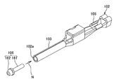
- FIG. 8 is an exploded perspective view showing the terminal shown in FIG.
- the conventional terminal 101 includes a terminal fitting 102 and a cap 106.
- the male terminal fitting 102 which is the conventional terminal fitting includes an inserter 103 connected to a mating female terminal fitting (not shown), and the inserter 103. And a wire connecting portion 105 connected to the wire 10.
- the terminal fitting 102 is obtained by punching or bending a metal plate. The terminal fitting 102 is inserted into the terminal accommodating chamber of the housing from the inserter 103 side.
- the inserter 103 is obtained by subjecting a punched metal plate to roll forming or the like. That is, the inserter 103 is formed in a cylindrical shape. In addition, the inserter 103 is provided with an insertion port 102a (shown in FIG. 8) into which the cap 106 is inserted at the end of the inserter 103 away from the wire connecting portion 105, that is, at the tip of the terminal fitting 102. Yes.
- the cap 106 includes a columnar shaft portion 161 that is inserted inside the inserter 103, and a head portion 162 that is provided at an end portion of the shaft portion 161 and has a larger diameter than the shaft portion 161. .
- the cap 106 is made of a synthetic resin.
- the cap 106 is inserted inside the inserter 103 along the longitudinal direction N (shown in FIG. 8) of the terminal fitting 102.
- the cap 106 is attached to prevent the inserter 103 of the terminal fitting 102 from damaging the inner wall of the terminal accommodating chamber when the terminal 101 is inserted into the terminal accommodating chamber of the housing.
- the cap 106 is attached to prevent the inserter 103 from damaging the inner wall of the electrical contact portion of the female terminal fitting when the inserter 103 is inserted into the electrical contact portion of the female terminal fitting. It has been.
- the adhesive 109 is applied in advance to the outer peripheral surface of the shaft part 161 of the cap 106, and the shaft part 161 applied with the adhesive 109 is inserted into the inserter 102a from the insertion port 102a. Insert into 103. In this way, the cap 106 is attached to the inserter 103.
- the conventional terminal 101 described above has the following problems. That is, the terminal 101 has a problem that it is difficult to uniformly apply the adhesive 109 to the shaft portion 161 of the cap 106, and the cap 106 cannot be securely attached to the terminal fitting 102. Further, it takes time and effort to uniformly apply the adhesive 109 to the shaft portion 161 of the cap 106, and there is a problem that it may take a long time to attach the cap 106 to the terminal fitting 102. It was.
- an object of the present invention is to solve the above problems. That is, an object of the present invention is to provide a terminal that can save the trouble of attaching the cap to the inserter, and can provide the cap on the inserter in a short time, and a method of forming the terminal cap.
- the insert in the terminal in which the cap made of resin is provided at the tip of the cylindrical insert, the insert has an annular portion having a smaller diameter than the insert at the tip.
- the cap is provided on the insert by covering the annular portion and dipping to the inside away from the tip of the insert than the annular portion. is there.
- an annular portion having a smaller diameter than the inserter is provided at a distal end portion of the cylindrical inserter, covers the annular portion, and from the distal end of the inserter than the annular portion.
- the terminal cap forming method is characterized in that the cap is provided on the inserter by dipping to the inner side away.
- the annular portion is formed by subjecting the inserter to radial pressing.
- the inserter in the terminal in which the cap made of resin is provided at the distal end portion of the cylindrical inserter, the inserter has a distal end portion that is more than the inserter. Since a small-diameter annular portion is provided, the cap covers the annular portion, and is provided in the insert by being dipped to the inside away from the tip of the insert than the annular portion. The trouble of attaching the cap to the inserter can be saved, and the cap can be provided on the inserter in a short time.
- the annular portion is formed by pressing the inserter, the labor for forming the annular portion is reduced, and therefore the terminal is provided.
- the time required for manufacturing can be shortened, and the production efficiency can be improved.
- FIG. 8 is an exploded perspective view showing the terminal shown in FIG. 7.
- the terminal 1 comprises the wire harness routed by the electric vehicle.
- the wire harness includes an electric wire 10 and a connector (not shown) attached to the end of the electric wire 10.
- the connector includes a terminal 1 provided with a terminal fitting 2 connected to an electric wire and a cap 6 provided at a tip end portion of the terminal fitting 2, and a housing provided with a terminal accommodating portion (not shown) for accommodating the terminal 1. (Not shown).
- the housing is made of an insulating synthetic resin.
- the terminal fitting 2 is connected to a wire 10 connected to an inserter 3 connected to a mating female terminal fitting (not shown), a housing mounting portion 4 connected to the inserter 3, and the housing mounting portion 4.
- the terminal fitting 2 is obtained by punching or bending a metal plate.
- the terminal fitting 2 is inserted into the terminal accommodating portion of the housing from the inserter 3 side in a state where the electric wire connecting portion 5 is connected to the electric wire 10.
- the terminal fitting 2 is inserted into the mating terminal fitting from the side of the inserter 3 and is electrically connected to the mating terminal fitting.
- the terminal fitting 2 is provided with a cap 6 made of an insulating synthetic resin at the tip thereof, that is, the tip of the insert 3.
- the inserter 3 is obtained by subjecting a punched metal plate to roll forming or the like. That is, the inserter 3 is formed in a cylindrical shape by bringing both ends of the punched metal plate close to each other and mating. For this reason, a slit 30 (shown in FIG. 2) extending from one end to the other end in the tube length direction of the inserter 3 is formed between the end portions of the metal plates brought close to each other.
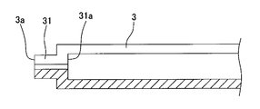
- the insert 3 is provided with an annular portion 31 having a smaller diameter than the insert 3 at the tip.
- the annular portion 31 is formed in an annular shape by subjecting the inserter 3 to radial pressing.
- the annular portion 31 protrudes inward from the inner surface of the inserter 3 toward each other.
- the annular portion 31 protrudes from the inserter 3 in the tube length direction of the inserter 3.
- the housing mounting portion 4 includes a bottom wall 41, a pair of side walls 42 erected from both ends in the width direction of the bottom wall 41, and a top wall 43 that connects the pair of side walls 42. And is formed in a rectangular tube shape.
- the bottom wall 41 and the pair of side walls 42 are connected to the side away from the annular portion 31 of the insert 3 described above.
- the electric wire connecting portion 5 is connected to the bottom wall 41, a base wall 51 that positions the electric wire 10 on the surface, and a pair of core wires that are erected from both ends in the width direction of the base wall 51 and crimp the core wire 11 of the electric wire 10
- a crimping piece 52 and a pair of insulation coating crimping pieces 53 that stand up from both ends of the base wall 51 in the width direction and crimp the insulation coating of the electric wire 10 are provided.
- the base wall 51 is formed in the shape of a bowl having a circular cross section.
- the pair of core wire crimping pieces 52 are provided closer to the housing mounting portion 4 than the pair of insulating coating crimping pieces 53.
- the electric wire connection portion 5 is formed by placing the core wire 11 portion of the electric wire 10 on the base wall 51 after the electric wire 10 having a round cross section in a state where the end portion is peeled and the core wire 11 is exposed is placed on the base wall 51.
- the core wire crimping piece 52 is bent in the pressing direction, that is, the core wire crimping piece 52 is used to caulk the core wire 11 portion to be electrically connected to the electric wire.
- the insulation coating crimping piece 53 is bent in a direction in which the coating portion of the electric wire 10 is pressed toward the base wall 51, that is, the insulation coating crimping piece 53 is crimped to fix the wire to the electric wire. .
- the cap 6 includes an embedded portion 61 embedded inside the inserter 3 and an exposed portion 62 exposed to the outside of the inserter 3.
- the embedded portion 61 is provided inside the annular portion 31 and inside a portion where the annular portion 31 of the inserter 3 is not provided. That is, the embedded portion 61 is provided from the tip 3 a of the annular portion 31, that is, from the tip 3 a of the inserter 3 to the housing attachment portion 4 side of the annular portion 31.
- the portion of the embedded portion 61 closer to the housing attachment portion 4 than the annular portion 31 is closer to the housing attachment portion 4 side of the annular portion 31. It comes into contact with the end surface 31a (shown in FIG. 5) and prevents the cap 6 from coming out of the terminal fitting 2.
- the exposed portion 62 covers the annular portion 31.
- the exposed portion 62 is provided with a tapered surface 62a.
- the tapered surface 62 a is continuous with the outer surface of the inserter 3, and is inclined in the diameter reducing direction of the inserter 3 as it goes away from the terminal 1.
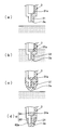
- the insert 3 is formed by punching and rolling the metal plate in advance, and the annular portion 31 is formed by pressing the end of the insert 3.
- the thermoplastic resin is heated and melted in a metallic container, and the inserter 3 is inserted into the molten thermoplastic resin from the tip 3a side. Immerse it to the housing mounting part 4 side rather than the annular part 31.
- the terminal metal fitting 2 is pulled up from the molten thermoplastic resin in a container, and a thermoplastic resin is hardened by cooling.
- the taper surface 62a is formed by removing the extraneous material on the outer periphery of the insert 3, that is, the thermoplastic resin on the outer periphery of the insert 3 (for example, cutting it into a tapered shape). .
- the tapered surface 62a may be formed by the weight of the thermoplastic resin. In this way, the cap 6 is formed.
- the cap 6 may be formed using a thermosetting resin that is cured by heating.
- the insert 3 is immersed in the thermosetting resin that is liquid at room temperature in the container from the tip 3a side of the insert 3 to the housing mounting portion 4 side rather than the annular portion 31.
- you may harden a thermosetting resin by pulling up the terminal metal fitting 2 from the liquid thermosetting resin in a container, and heating with a heater.
- the inserter 3 is provided with the annular portion 31 having a smaller diameter than the inserter 3 at the distal end thereof, and the cap 6 covers the annular portion 31 and the annular portion 31. Since it is provided in the inserter 3 by being dipped to the inside away from the tip 3a of the inserter 3, it is possible to save the trouble of attaching the cap 6 to the inserter 3 in a short time.
- a cap 6 can be provided on the insert 3.
- the said annular part 31 is formed by performing the press work to the said inserter 3, it will reduce the effort for forming the annular part 31, and it takes when manufacturing the terminal 1 for that. The required time can be shortened and the production efficiency can be improved.
- the annular portion 31 protrudes from the inserter 3 in the cylinder length direction.
- the present invention is not limited to this, and the inner direction approaching each other from the inner surface of the inserter 3. As long as it protrudes from the inserter 3 in the tube length direction.
Landscapes
- Engineering & Computer Science (AREA)
- Manufacturing & Machinery (AREA)
- Connector Housings Or Holding Contact Members (AREA)
- Connections Effected By Soldering, Adhesion, Or Permanent Deformation (AREA)
- Manufacturing Of Electrical Connectors (AREA)
Abstract
Priority Applications (3)
| Application Number | Priority Date | Filing Date | Title |
|---|---|---|---|
| EP12802371.0A EP2722934B1 (fr) | 2011-06-20 | 2012-05-31 | Borne et procédé de formation de capuchon de borne |
| US14/126,887 US9225092B2 (en) | 2011-06-20 | 2012-05-31 | Terminal and method of forming cap of terminal |
| CN201280030625.1A CN103636070B (zh) | 2011-06-20 | 2012-05-31 | 端子及端子帽部的形成方法 |
Applications Claiming Priority (2)
| Application Number | Priority Date | Filing Date | Title |
|---|---|---|---|
| JP2011135976A JP5705042B2 (ja) | 2011-06-20 | 2011-06-20 | 端子、及び、端子のキャップ形成方法 |
| JP2011-135976 | 2011-06-20 |
Publications (1)
| Publication Number | Publication Date |
|---|---|
| WO2012176597A1 true WO2012176597A1 (fr) | 2012-12-27 |
Family
ID=47422437
Family Applications (1)
| Application Number | Title | Priority Date | Filing Date |
|---|---|---|---|
| PCT/JP2012/064041 Ceased WO2012176597A1 (fr) | 2011-06-20 | 2012-05-31 | Borne et procédé de formation de capuchon de borne |
Country Status (5)
| Country | Link |
|---|---|
| US (1) | US9225092B2 (fr) |
| EP (1) | EP2722934B1 (fr) |
| JP (1) | JP5705042B2 (fr) |
| CN (1) | CN103636070B (fr) |
| WO (1) | WO2012176597A1 (fr) |
Families Citing this family (4)
| Publication number | Priority date | Publication date | Assignee | Title |
|---|---|---|---|---|
| USD728177S1 (en) * | 2013-02-01 | 2015-04-28 | Ebara Corporation | Roller shaft for substrate cleaning |
| USD735427S1 (en) * | 2013-02-01 | 2015-07-28 | Ebara Corporation | Roller shaft for substrate cleaning |
| CN107221909A (zh) * | 2017-07-07 | 2017-09-29 | 上海长园电子材料有限公司 | 快速封帽制造系统 |
| JP2025012042A (ja) | 2023-07-12 | 2025-01-24 | 住友電装株式会社 | 端子および端子の製造方法 |
Citations (4)
| Publication number | Priority date | Publication date | Assignee | Title |
|---|---|---|---|---|
| JPS5018995U (fr) * | 1973-06-15 | 1975-03-03 | ||
| JPS6281381U (fr) * | 1985-11-11 | 1987-05-25 | ||
| JP2000091014A (ja) | 1998-09-10 | 2000-03-31 | Yazaki Corp | 端子金具 |
| JP2003017168A (ja) * | 2001-07-03 | 2003-01-17 | Auto Network Gijutsu Kenkyusho:Kk | 端子の結合構造 |
Family Cites Families (9)
| Publication number | Priority date | Publication date | Assignee | Title |
|---|---|---|---|---|
| GB9603632D0 (en) * | 1996-02-21 | 1996-04-17 | Amp Italia | Sealed electrical connector |
| US6159046A (en) * | 1999-07-12 | 2000-12-12 | Wong; Shen-Chia | End connector and guide tube for a coaxial cable |
| US6179656B1 (en) * | 1999-07-12 | 2001-01-30 | Shen-Chia Wong | Guide tube for coupling an end connector to a coaxial cable |
| US6352448B1 (en) * | 2000-09-08 | 2002-03-05 | Randall A. Holliday | Cable TV end connector starter guide |
| US6537091B2 (en) | 2000-11-28 | 2003-03-25 | Autonetworks Technologies, Ltd. | Arc discharge suppressive terminal, method for producing such terminal, and arc discharge suppressive connector |
| US6361364B1 (en) * | 2001-03-02 | 2002-03-26 | Michael Holland | Solderless connector for a coaxial microcable |
| US6963780B2 (en) * | 2002-01-31 | 2005-11-08 | Medtronic, Inc. | Implantable medical device including a surface-mount terminal array |
| CN2553532Y (zh) * | 2002-06-26 | 2003-05-28 | 章鸿斌 | 一种香蕉插头 |
| US6805583B2 (en) * | 2002-12-06 | 2004-10-19 | Randall A. Holliday | Mini-coax cable connector and method of installation |
-
2011
- 2011-06-20 JP JP2011135976A patent/JP5705042B2/ja active Active
-
2012
- 2012-05-31 CN CN201280030625.1A patent/CN103636070B/zh active Active
- 2012-05-31 WO PCT/JP2012/064041 patent/WO2012176597A1/fr not_active Ceased
- 2012-05-31 US US14/126,887 patent/US9225092B2/en active Active
- 2012-05-31 EP EP12802371.0A patent/EP2722934B1/fr active Active
Patent Citations (4)
| Publication number | Priority date | Publication date | Assignee | Title |
|---|---|---|---|---|
| JPS5018995U (fr) * | 1973-06-15 | 1975-03-03 | ||
| JPS6281381U (fr) * | 1985-11-11 | 1987-05-25 | ||
| JP2000091014A (ja) | 1998-09-10 | 2000-03-31 | Yazaki Corp | 端子金具 |
| JP2003017168A (ja) * | 2001-07-03 | 2003-01-17 | Auto Network Gijutsu Kenkyusho:Kk | 端子の結合構造 |
Also Published As
| Publication number | Publication date |
|---|---|
| CN103636070A (zh) | 2014-03-12 |
| JP5705042B2 (ja) | 2015-04-22 |
| EP2722934A1 (fr) | 2014-04-23 |
| US9225092B2 (en) | 2015-12-29 |
| US20140295716A1 (en) | 2014-10-02 |
| CN103636070B (zh) | 2016-03-09 |
| EP2722934B1 (fr) | 2017-07-12 |
| JP2013004391A (ja) | 2013-01-07 |
| EP2722934A4 (fr) | 2015-03-18 |
Similar Documents
| Publication | Publication Date | Title |
|---|---|---|
| JP5391173B2 (ja) | 電線と端子の接続構造及び接続装置、接続方法、ワイヤーハーネス | |
| CN105284007B (zh) | 包覆电线的末端构造 | |
| JP5567234B1 (ja) | 接続構造体、端子圧着部材、ワイヤハーネス、コネクタ、接続構造体の圧着方法及びその圧着する圧着装置 | |
| US20140349501A1 (en) | Terminal-attached wire and terminal | |
| US7364478B2 (en) | Connector and method for manufacturing and connecting wire | |
| JP2014187039A5 (fr) | ||
| JP5705042B2 (ja) | 端子、及び、端子のキャップ形成方法 | |
| CN113939957B (zh) | 用于机动车辆电器网络导线的电气连接座 | |
| US20200266595A1 (en) | Electric Line Assembly with Direct Contacting and Method for Producing Same | |
| JP2018190617A (ja) | 端子付き電線 | |
| JP5534516B2 (ja) | インナー端子の成形方法及びインナー端子成形型 | |
| CN111133638B (zh) | 电器件和用于制造电器件的绞合线接触机构的方法 | |
| JP5500384B2 (ja) | 端子金具付き電線および端子金具付き電線の製造方法 | |
| CN111133539B (zh) | 具有端子区域的电器件和用于制造端子区域的方法 | |
| JP2013254658A (ja) | 圧着端子 | |
| EP3016207B1 (fr) | Structure de traitement imperméable à l'eau pour un élément linéaire | |
| JP2010080193A (ja) | 端子金具、端子金具付き電線、及び端子金具付き電線の製造方法 | |
| JP2005100704A (ja) | ワイヤーハーネスのスプライス構造 | |
| JP5830479B2 (ja) | ワイヤハーネス | |
| JP2016024923A (ja) | 半田接合構造 | |
| JP2015133270A (ja) | 被覆電線、接続構造体、ワイヤハーネス、コネクタ、並びに被覆電線、及び接続構造体の製造方法 | |
| JP2015082418A (ja) | 電線及び電線の製造方法 | |
| JP2016046220A (ja) | 端子付き電線及びその製造方法 | |
| JP2010157396A (ja) | コネクタ及びその製造方法 | |
| JP2014160577A (ja) | 圧着端子および圧着端子を用いたワイヤハーネス |
Legal Events
| Date | Code | Title | Description |
|---|---|---|---|
| WWE | Wipo information: entry into national phase |
Ref document number: 201280030625.1 Country of ref document: CN |
|
| 121 | Ep: the epo has been informed by wipo that ep was designated in this application |
Ref document number: 12802371 Country of ref document: EP Kind code of ref document: A1 |
|
| NENP | Non-entry into the national phase |
Ref country code: DE |
|
| REEP | Request for entry into the european phase |
Ref document number: 2012802371 Country of ref document: EP |
|
| WWE | Wipo information: entry into national phase |
Ref document number: 2012802371 Country of ref document: EP |
|
| WWE | Wipo information: entry into national phase |
Ref document number: 14126887 Country of ref document: US |