WO2012176609A1 - Poignée de porte pour véhicule - Google Patents
Poignée de porte pour véhicule Download PDFInfo
- Publication number
- WO2012176609A1 WO2012176609A1 PCT/JP2012/064372 JP2012064372W WO2012176609A1 WO 2012176609 A1 WO2012176609 A1 WO 2012176609A1 JP 2012064372 W JP2012064372 W JP 2012064372W WO 2012176609 A1 WO2012176609 A1 WO 2012176609A1
- Authority
- WO
- WIPO (PCT)
- Prior art keywords
- handle
- pin
- hole
- vehicle door
- door handle
- Prior art date
- Legal status (The legal status is an assumption and is not a legal conclusion. Google has not performed a legal analysis and makes no representation as to the accuracy of the status listed.)
- Ceased
Links
Images










Classifications
-
- E—FIXED CONSTRUCTIONS
- E05—LOCKS; KEYS; WINDOW OR DOOR FITTINGS; SAFES
- E05B—LOCKS; ACCESSORIES THEREFOR; HANDCUFFS
- E05B1/00—Knobs or handles for wings; Knobs, handles, or press buttons for locks or latches on wings
-
- E—FIXED CONSTRUCTIONS
- E05—LOCKS; KEYS; WINDOW OR DOOR FITTINGS; SAFES
- E05B—LOCKS; ACCESSORIES THEREFOR; HANDCUFFS
- E05B85/00—Details of vehicle locks not provided for in groups E05B77/00 - E05B83/00
- E05B85/10—Handles
- E05B85/14—Handles pivoted about an axis parallel to the wing
- E05B85/16—Handles pivoted about an axis parallel to the wing a longitudinal grip part being pivoted at one end about an axis perpendicular to the longitudinal axis of the grip part
-
- Y—GENERAL TAGGING OF NEW TECHNOLOGICAL DEVELOPMENTS; GENERAL TAGGING OF CROSS-SECTIONAL TECHNOLOGIES SPANNING OVER SEVERAL SECTIONS OF THE IPC; TECHNICAL SUBJECTS COVERED BY FORMER USPC CROSS-REFERENCE ART COLLECTIONS [XRACs] AND DIGESTS
- Y10—TECHNICAL SUBJECTS COVERED BY FORMER USPC
- Y10T—TECHNICAL SUBJECTS COVERED BY FORMER US CLASSIFICATION
- Y10T292/00—Closure fasteners
- Y10T292/57—Operators with knobs or handles
Definitions
- the present invention relates to a vehicle door handle mounted on the outside of the door for opening and closing the vehicle door.
- Patent Document 1 This type of vehicle door handle is shown, for example, in Patent Document 1 below, and includes a resin handle body (described as a housing member in Patent Document 1 below) and a resin handle cover (Patent Document 1 below).
- Patent Document 1 it is configured to be attached to the outside of the door of the vehicle in a state of being integrally combined.
- a front arm and a rear arm are formed on a housing member (an outer member arranged outside when mounted on the outside of a door), and decoration (for example, painting or plating) is formed on the outer surface of the housing member. ) Is given. For this reason, when decorating the outer surface of the housing member, masking may be performed so that painting or plating may not adhere to the front arm and rear arm that do not require decoration, or coating or plating may not adhere to the front arm and rear arm. There is a need.
- a resin handle body having an engaging projection and a first arm (for example, a rear arm) on one end side, and a pin through hole and a second arm (for example, a front arm) on the other end side;
- the engaging convex part is connected to the one end side so that the engaging convex part can be tilted, and the other end side has a connecting pin that is inserted through the pin through hole and penetrates the pin through hole.
- decoration for example, painting, plating, etc.
- a vehicle door handle mounted on the outside of a vehicle door in a state where the handle main body and the handle cover are integrally combined is a feature.
- the pin through hole may be formed in an elliptical shape having a long diameter in the longitudinal direction of the vehicle door handle or a long hole shape long in the longitudinal direction of the vehicle door handle.
- the handle body may be a guide (for example, integral with the handle body) capable of guiding the connecting pin of the handle cover to the pin through-hole of the handle body when the handle body and the handle cover are joined. It is also possible to be provided with a rib formed on or an electronic component assembled to the handle body.
- a locking portion for stopping a decorative jig (for example, a jig used when decorating the outer surface of the handle cover such as painting or plating) is integrally provided on the inside of the handle cover. It is possible that it is formed.
- the handle body has a first arm and a second arm, and each handle cover whose decoration (for example, painting, plating, etc.) is applied to the outer surface is provided for each handle cover.
- decoration for example, painting, plating, etc.
- the handle main body and the handle cover are connected to the engaging convex portion formed on the handle main body and the engaging concave portion formed on the handle cover, and the connecting pin formed on the handle cover is connected to the pin formed on the handle main body.
- the connecting pin is welded and fixed to the pin through-hole so as to be united together.
- a fastening member such as a screw and a welding nut (parts different from the handle main body and the handle cover) is not required for integrally combining the handle main body and the handle cover.
- the connecting pin can be smoothly fitted into the pin through hole.
- the handle body is provided with a guide capable of guiding the connection pin of the handle cover to the pin through hole of the handle body when the handle body and the handle cover are joined, It is possible to smoothly join the main body and the handle cover.
- a locking portion for stopping a decorative jig is integrally formed on the inside of the handle cover, it is possible to easily perform the work of decorating at least the outer surface of the handle cover. Is possible.
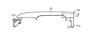
- FIG. 1 is a front view showing an embodiment of a vehicle door handle according to the present invention.
- FIG. 2 is a right side view of the vehicle door handle shown in FIG.
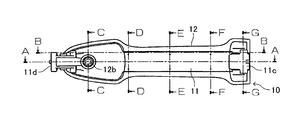
- FIG. 3 is a bottom view of the vehicle door handle shown in FIG. 4 is an end view of a cross section taken along line AA of FIG.
- FIG. 5 is an end view of a cross section taken along line BB of FIG.
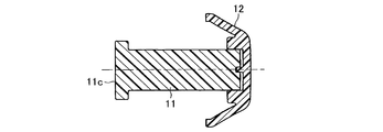
- FIG. 6 is an enlarged end view of a cross section taken along the line CC of FIG.
- FIG. 9 is an enlarged end view of a cross section taken along line FF of FIG. FIG.
- FIG. 10 is an enlarged end view of a cross section taken along line GG in FIG.
- FIG. 11 is an enlarged end view of a cross section taken along line HH of FIG.
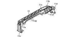
- FIG. 12 is an outer perspective view of the handle body shown in FIGS.
- FIG. 13 is an inner perspective view of the handle body shown in FIGS.
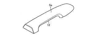
- FIG. 14 is an outer perspective view of the handle cover shown in FIGS.
- FIG. 15 is a perspective view of the inside of the handle cover shown in FIGS.
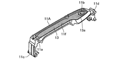
- FIG. 16 is an outer perspective view showing a modified embodiment of the handle body.
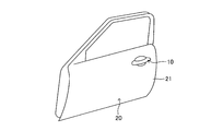
- FIG. 17 is a schematic perspective view of a state in which the vehicle door handle according to the present invention is attached to the outside of the vehicle door.
- FIGS. 1 to 11 show an embodiment of a vehicle door handle according to the present invention.
- the vehicle door handle 10 includes a resin handle body 11 and a resin handle cover 12, and the handle body. 11 and the handle cover 12 are configured to be mounted on the outside of the vehicle door 20 (see the side door in FIG. 17) in an integrated state as shown in FIGS. Yes.
- the handle body 11 is an inner member that is disposed on the inner side in a state of being attached to the outer side of the door 20, and as shown in FIGS. 1 to 11, 12, and 13, one end (on the door 20 of the vehicle) A pair of engaging projections 11a are provided at the rear end portion when assembled and one end is provided at the other end portion (the front end portion when assembled to the vehicle door 20). It has a pin through-hole 11b, and a first arm (rear arm) 11c is formed at one end, and a second arm (front arm) 11d is formed at the other end.
- the pin through-hole 11b is a stepped through-hole, and as shown in FIGS. 4 and 6, the inner side (the lower side in FIG. 4, the left side in FIG. 6) has a large diameter.
- the first arm (rear arm) 11c extends through the door outer panel 21 and extends into the door 20 when the vehicle door handle 10 is mounted on the outside of the door 20. It is comprised so that it may interlock
- the second arm (front arm) 11d extends through the door outer panel 21 and into the door 20 when the vehicle door handle 10 is mounted outside the door 20, It is configured to be rotatably supported by a support member (not shown) fixed inside the door outer panel 21.
- the handle body 11 has a reinforcing rib R.
- the reinforcing rib R is provided at the center portion of the handle body 11 (that is, the portion pressed to the outside of the vehicle when the vehicle door handle 10 is operated).
- the reinforcing rib R is erected so as to exhibit a substantially square shape along with the side wall of the handle body 11 and is erected in a manner of connecting diagonal lines of the substantially rectangular shape. For this reason, when the vehicle door handle 10 is operated, the central portion of the handle body 11 is hardly bent by the reinforcing rib R, and the operation feeling of the vehicle door handle 10 is improved.
- the handle cover 12 is an outer member disposed on the outer side in a state of being attached to the outer side of the door 20, and is integrally formed on the outer side of the handle main body 11, as shown in FIGS. 1 to 11, 14, and 15. And has a pair of engagement recesses 12a to which the engagement projection 11a is tiltably connected at one end, and is inserted into the pin through hole 11b at the other end.
- the stepped connecting pin 12b that penetrates the pin through-hole 11b is provided, and at least the outer surface (outer surface) Sa is decorated (for example, painting or plating).
- the handle cover 12 is in a state where the engaging convex portion 11a and the engaging concave portion 12a are connected and the small diameter portion of the connecting pin 12b is inserted into the small diameter portion of the pin through hole 11b (see the phantom line in FIG. 4).
- the distal end portion of the connecting pin 12b is heat caulked and fixed to the large diameter portion of the pin through hole 11b (the distal end portion (small diameter portion) of the connecting pin 12b is thicker than the small diameter portion of the pin through hole 11b to prevent the pin from coming off).
- the first arm 11c and the second arm 11d are formed on the handle main body 11, and decoration (for example, painting or It is not necessary to provide each arm on the handle cover 12 to be plated. For this reason, when decorating the outer surface Sa of the handle cover 12 with, for example, painting or plating, it is necessary to perform masking so that the coating or plating is not unnecessarily adhered to the decoration unnecessary portion (each arm). Absent.
- the handle main body 11 and the handle cover 12 are connected to the pair of engaging convex portions 11 a formed on the handle main body 11 and the pair of engaging concave portions 12 a formed on the handle cover 12.
- the connecting pin 12b is formed in a state where the connecting pin 12b formed in the handle cover 12 is inserted into the pin through hole 11b formed in the handle main body 11 (a state in which the handle main body 11 and the handle cover 12 are combined and joined). It is united integrally by being fixed by heat caulking to the pin through hole 11b. For this reason, in this embodiment, in order to unite the handle body 11 and the handle cover 12 together, a fastening member such as a screw and a welding nut (parts different from the handle body 11 and the handle cover 12) is unnecessary.
- the pin through hole 11b formed in the handle main body 11 has a long hole shape that is long in the longitudinal direction of the vehicle door handle 10 (the longitudinal direction of the vehicle door handle 10 is It can also be implemented in an elliptical shape with a long diameter. For this reason, in this embodiment, when the handle body 11 and the handle cover 12 are combined and joined, the connecting pin 12b can be smoothly fitted into the pin through hole 11b.
- the handle body 11 is provided with a guide 11e.
- the handle main body 11 and the handle cover 12 are joined in a state in which the engaging convex portion 11a and the engaging concave portion 12a are connected (specifically, the engaging convex portion 11a is fitted into the engaging concave portion 12a.
- the connecting pin 12b is inserted into the pin through hole 11b by tilting the handle body 11 relative to the handle cover 12
- the connecting pin 12b is guided to the pin through hole 11b by the guide 11e. It is comprised so that.
- the guide 11e is one of the ribs erected on the outer side of the handle body 11, and has a guide surface 11e1 that is inclined from the center side of the handle body 11 toward the pin through hole 11b.
- the guide surface 11e1 guides the distal end surface 12b1 of the connecting pin 12b, whereby the connecting pin 12b is guided to the pin through hole 11b. For this reason, in this embodiment, the joining operation of the handle body 11 and the handle cover 12 can be performed smoothly.
- a pair of locking portions 12 f for stopping a decorative jig (not shown) inside the handle cover 12. are integrally formed. For this reason, in this embodiment, it is possible to easily perform the work of decorating at least the outer surface Sa of the handle cover 12.
- the vehicle door handle 10 is configured by the resin handle body 11 and the resin handle cover 12.
- FIG. It is also possible to configure and implement the resin handle body 11A and the electronic component 13 (shaded members) shown in the figure.
- the handle main body 11A has the configuration of the handle main body 11 of the above-described embodiment except that the outer shape of the handle main body 11A is formed with an accommodation recess 11f in which the electronic component 13 is assembled instead of the rib (guide 11e). It is substantially the same, and has a pair of engaging convex portions 11a, one pin through hole 11b, a first arm (rear arm) 11c, a second arm (front arm) 11d, and the like.
- the electronic component 13 is, for example, a functional component equivalent to the electronic component described in Japanese Patent No. 4543722 and Japanese Patent No. 4600323 of Patent Document 1 described in the headline, and the handle main body 11A and the handle cover 12 are integrated. Before being united, it is assembled to the housing recess 11f of the handle body 11A.
- the electronic component 13 has the same function as the guide 11e of the above-described embodiment. More specifically, the leading end surface 12b1 of the connecting pin 12b is guided by the outer surface 13a of the electronic component 13, whereby the connecting pin 12b is guided to the pin through hole 11b.
- the embodiment has been described on the assumption that the vehicle door handle 10 is attached to the side door (front side door, rear side door) of the vehicle. In the case where it is mounted on the back door of the vehicle, it can be carried out in the same manner or with appropriate modifications.
- tip part of the connection pin 12b was fixed by heat caulking with respect to the large diameter part of the pin through-hole 11b, the front-end
Landscapes
- Lock And Its Accessories (AREA)
Abstract
Priority Applications (2)
| Application Number | Priority Date | Filing Date | Title |
|---|---|---|---|
| US14/128,364 US20140125072A1 (en) | 2011-06-22 | 2012-06-04 | Door handle for vehicle |
| CN201290000615.9U CN203669502U (zh) | 2011-06-22 | 2012-06-04 | 车辆用门把手 |
Applications Claiming Priority (2)
| Application Number | Priority Date | Filing Date | Title |
|---|---|---|---|
| JP2011138479A JP5382374B2 (ja) | 2011-06-22 | 2011-06-22 | 車両用ドアハンドル |
| JP2011-138479 | 2011-06-22 |
Publications (1)
| Publication Number | Publication Date |
|---|---|
| WO2012176609A1 true WO2012176609A1 (fr) | 2012-12-27 |
Family
ID=47422449
Family Applications (1)
| Application Number | Title | Priority Date | Filing Date |
|---|---|---|---|
| PCT/JP2012/064372 Ceased WO2012176609A1 (fr) | 2011-06-22 | 2012-06-04 | Poignée de porte pour véhicule |
Country Status (4)
| Country | Link |
|---|---|
| US (1) | US20140125072A1 (fr) |
| JP (1) | JP5382374B2 (fr) |
| CN (1) | CN203669502U (fr) |
| WO (1) | WO2012176609A1 (fr) |
Families Citing this family (6)
| Publication number | Priority date | Publication date | Assignee | Title |
|---|---|---|---|---|
| JP6064806B2 (ja) * | 2013-06-21 | 2017-01-25 | アイシン精機株式会社 | 車両用のドアハンドル |
| JP6222851B2 (ja) * | 2015-04-10 | 2017-11-01 | サカエ理研工業株式会社 | 車両用ドアハンドル部材 |
| WO2018015865A1 (fr) * | 2016-07-20 | 2018-01-25 | MOTHERSON AUTOMOTIVE TECHNOLOGIES & ENGINEERING (A Division of Motherson Sumi Systems Ltd.) | Ensemble poignée de porte |
| JP1576171S (fr) * | 2016-09-30 | 2017-10-30 | ||
| JP7064993B2 (ja) * | 2018-08-08 | 2022-05-11 | 株式会社アルファ | 車両のドアハンドル |
| US20200243821A1 (en) * | 2019-01-29 | 2020-07-30 | Exide Technologies | Battery having a flat top cover configuration including centerline battery cell vents, a centerline handle configured to collapse to a recessed state and to wrap around terminals, and side flame arrestor vent |
Citations (2)
| Publication number | Priority date | Publication date | Assignee | Title |
|---|---|---|---|---|
| JP2009228292A (ja) * | 2008-03-21 | 2009-10-08 | Alpha Corp | 表裏カバー連結品 |
| JP2010261217A (ja) * | 2009-05-07 | 2010-11-18 | Sakae Riken Kogyo Co Ltd | 車両用ドアハンドル装置、及びその組付け方法 |
Family Cites Families (13)
| Publication number | Priority date | Publication date | Assignee | Title |
|---|---|---|---|---|
| US1496435A (en) * | 1924-06-03 | sobeng | ||
| US5505505A (en) * | 1994-05-10 | 1996-04-09 | Vanguard Plastics (1971) Ltd. | Device for securing a closure such as a window |
| JP4342207B2 (ja) * | 2003-04-22 | 2009-10-14 | アイシン精機株式会社 | 車両用ドアハンドル装置 |
| GB2421799B (en) * | 2003-06-20 | 2006-11-15 | Honda Lock Kk | Vehicle door outer handle system |
| JP4052277B2 (ja) * | 2004-04-19 | 2008-02-27 | アイシン精機株式会社 | 車両用ドアハンドル装置 |
| US7201415B2 (en) * | 2004-12-14 | 2007-04-10 | Putco, Inc. | Method and apparatus for applying a decorative design to a door handle |
| CN1924261B (zh) * | 2005-08-31 | 2011-07-06 | 株式会社有信 | 车辆用门把手装置 |
| JP4639141B2 (ja) * | 2005-11-18 | 2011-02-23 | 株式会社ホンダロック | アンテナ内蔵装置 |
| US7475925B2 (en) * | 2006-09-20 | 2009-01-13 | Taiwan Fu Hsing Industrial Co., Ltd. | Combination structure of base plate and escutcheon |
| WO2008137634A1 (fr) * | 2007-05-03 | 2008-11-13 | Donnelly Corporation | Module d'éclairage pour un véhicule |
| JP5015709B2 (ja) * | 2007-09-24 | 2012-08-29 | 株式会社アンセイ | 車両用開閉体のストライカ及びその製造方法 |
| JP5270421B2 (ja) * | 2009-03-30 | 2013-08-21 | 株式会社アルファ | 車両のドアハンドル装置 |
| JP2011039027A (ja) * | 2009-07-14 | 2011-02-24 | Pacific Ind Co Ltd | 金属調樹脂カバー及びその製造方法並びに車両用ドアハンドル |
-
2011
- 2011-06-22 JP JP2011138479A patent/JP5382374B2/ja not_active Expired - Fee Related
-
2012
- 2012-06-04 CN CN201290000615.9U patent/CN203669502U/zh not_active Expired - Fee Related
- 2012-06-04 WO PCT/JP2012/064372 patent/WO2012176609A1/fr not_active Ceased
- 2012-06-04 US US14/128,364 patent/US20140125072A1/en not_active Abandoned
Patent Citations (2)
| Publication number | Priority date | Publication date | Assignee | Title |
|---|---|---|---|---|
| JP2009228292A (ja) * | 2008-03-21 | 2009-10-08 | Alpha Corp | 表裏カバー連結品 |
| JP2010261217A (ja) * | 2009-05-07 | 2010-11-18 | Sakae Riken Kogyo Co Ltd | 車両用ドアハンドル装置、及びその組付け方法 |
Also Published As
| Publication number | Publication date |
|---|---|
| CN203669502U (zh) | 2014-06-25 |
| US20140125072A1 (en) | 2014-05-08 |
| JP2013007158A (ja) | 2013-01-10 |
| JP5382374B2 (ja) | 2014-01-08 |
Similar Documents
| Publication | Publication Date | Title |
|---|---|---|
| JP5382374B2 (ja) | 車両用ドアハンドル | |
| JP5633994B2 (ja) | 車両用樹脂ドア構造 | |
| US8608238B2 (en) | Vehicle body structure for automobile | |
| CN103619632B (zh) | 变速装置及其制造方法 | |
| JP6706678B2 (ja) | 自動車のためのカバー構造 | |
| JP2006015905A (ja) | バンパ取付構造 | |
| CN105863409B (zh) | 车辆的车门内把手组装结构 | |
| JP2017210062A (ja) | 車体構造 | |
| EP2011722A1 (fr) | Raidisseur d'aile pour aile avant de véhicule automobile et aile avant comprenant un tel raidisseur d'aile | |
| JP2010023749A (ja) | 車両用インストルメントパネル上面部支持構造 | |
| JP5131914B2 (ja) | 車室前部構造 | |
| KR100808371B1 (ko) | 차량용 가니쉬 및 라인 몰딩 조립체 | |
| JP6172076B2 (ja) | トランクリッドヒンジ構造 | |
| JP2014237380A (ja) | 車両のアンダーカバー組付構造 | |
| JP2010076718A (ja) | 部材取付用ブラケットの締結構造 | |
| JP2008230604A (ja) | 自動車のヘッドランプおよびフロントターンランプの建付構造 | |
| JP6784938B2 (ja) | 車両用内装品の固定構造 | |
| JP2008074362A (ja) | 自動車用ボディパネルと取付部品との取付構造、及びロッカパネルとロッカプロテクタとの取付構造 | |
| JP2010101059A (ja) | インサイドハンドルの取付構造 | |
| JP5584009B2 (ja) | 車両用組付部品 | |
| KR20090027064A (ko) | 자동차 스티어링 휠의 오디오 스위치 조립체의 장착구조 | |
| KR20070025706A (ko) | 차량의 도어 인사이드 핸들 및 안전록크노브 케이블의연결구조 | |
| JP4135156B2 (ja) | ランプ用ハーネスの保護構造 | |
| JP2007131281A (ja) | バンパの取り付け構造 | |
| JP4262101B2 (ja) | 車両用ストライカ |
Legal Events
| Date | Code | Title | Description |
|---|---|---|---|
| WWE | Wipo information: entry into national phase |
Ref document number: 201290000615.9 Country of ref document: CN |
|
| 121 | Ep: the epo has been informed by wipo that ep was designated in this application |
Ref document number: 12803155 Country of ref document: EP Kind code of ref document: A1 |
|
| WWE | Wipo information: entry into national phase |
Ref document number: 14128364 Country of ref document: US |
|
| NENP | Non-entry into the national phase |
Ref country code: DE |
|
| 122 | Ep: pct application non-entry in european phase |
Ref document number: 12803155 Country of ref document: EP Kind code of ref document: A1 |