WO2012176612A1 - Procédé de détection par ultrasons de défaut de roue de véhicule - Google Patents
Procédé de détection par ultrasons de défaut de roue de véhicule Download PDFInfo
- Publication number
- WO2012176612A1 WO2012176612A1 PCT/JP2012/064433 JP2012064433W WO2012176612A1 WO 2012176612 A1 WO2012176612 A1 WO 2012176612A1 JP 2012064433 W JP2012064433 W JP 2012064433W WO 2012176612 A1 WO2012176612 A1 WO 2012176612A1
- Authority
- WO
- WIPO (PCT)
- Prior art keywords
- flaw
- wheel
- flange
- array probe
- echo
- Prior art date
- Legal status (The legal status is an assumption and is not a legal conclusion. Google has not performed a legal analysis and makes no representation as to the accuracy of the status listed.)
- Ceased
Links
Images


Classifications
-
- G—PHYSICS
- G01—MEASURING; TESTING
- G01N—INVESTIGATING OR ANALYSING MATERIALS BY DETERMINING THEIR CHEMICAL OR PHYSICAL PROPERTIES
- G01N29/00—Investigating or analysing materials by the use of ultrasonic, sonic or infrasonic waves; Visualisation of the interior of objects by transmitting ultrasonic or sonic waves through the object
- G01N29/04—Analysing solids
- G01N29/043—Analysing solids in the interior, e.g. by shear waves
-
- G—PHYSICS
- G01—MEASURING; TESTING
- G01N—INVESTIGATING OR ANALYSING MATERIALS BY DETERMINING THEIR CHEMICAL OR PHYSICAL PROPERTIES
- G01N29/00—Investigating or analysing materials by the use of ultrasonic, sonic or infrasonic waves; Visualisation of the interior of objects by transmitting ultrasonic or sonic waves through the object
- G01N29/04—Analysing solids
- G01N29/06—Visualisation of the interior, e.g. acoustic microscopy
- G01N29/0609—Display arrangements, e.g. colour displays
- G01N29/0645—Display representation or displayed parameters, e.g. A-, B- or C-Scan
-
- G—PHYSICS
- G01—MEASURING; TESTING
- G01N—INVESTIGATING OR ANALYSING MATERIALS BY DETERMINING THEIR CHEMICAL OR PHYSICAL PROPERTIES
- G01N29/00—Investigating or analysing materials by the use of ultrasonic, sonic or infrasonic waves; Visualisation of the interior of objects by transmitting ultrasonic or sonic waves through the object
- G01N29/04—Analysing solids
- G01N29/07—Analysing solids by measuring propagation velocity or propagation time of acoustic waves
-
- G—PHYSICS
- G01—MEASURING; TESTING
- G01N—INVESTIGATING OR ANALYSING MATERIALS BY DETERMINING THEIR CHEMICAL OR PHYSICAL PROPERTIES
- G01N29/00—Investigating or analysing materials by the use of ultrasonic, sonic or infrasonic waves; Visualisation of the interior of objects by transmitting ultrasonic or sonic waves through the object
- G01N29/22—Details, e.g. general constructional or apparatus details
- G01N29/24—Probes
-
- G—PHYSICS
- G01—MEASURING; TESTING
- G01N—INVESTIGATING OR ANALYSING MATERIALS BY DETERMINING THEIR CHEMICAL OR PHYSICAL PROPERTIES
- G01N29/00—Investigating or analysing materials by the use of ultrasonic, sonic or infrasonic waves; Visualisation of the interior of objects by transmitting ultrasonic or sonic waves through the object
- G01N29/22—Details, e.g. general constructional or apparatus details
- G01N29/28—Details, e.g. general constructional or apparatus details providing acoustic coupling, e.g. water
-
- G—PHYSICS
- G01—MEASURING; TESTING
- G01N—INVESTIGATING OR ANALYSING MATERIALS BY DETERMINING THEIR CHEMICAL OR PHYSICAL PROPERTIES
- G01N2291/00—Indexing codes associated with group G01N29/00
- G01N2291/04—Wave modes and trajectories
- G01N2291/044—Internal reflections (echoes), e.g. on walls or defects
-
- G—PHYSICS
- G01—MEASURING; TESTING
- G01N—INVESTIGATING OR ANALYSING MATERIALS BY DETERMINING THEIR CHEMICAL OR PHYSICAL PROPERTIES
- G01N2291/00—Indexing codes associated with group G01N29/00
- G01N2291/10—Number of transducers
- G01N2291/106—Number of transducers one or more transducer arrays
-
- G—PHYSICS
- G01—MEASURING; TESTING
- G01N—INVESTIGATING OR ANALYSING MATERIALS BY DETERMINING THEIR CHEMICAL OR PHYSICAL PROPERTIES
- G01N2291/00—Indexing codes associated with group G01N29/00
- G01N2291/26—Scanned objects
- G01N2291/263—Surfaces
- G01N2291/2638—Complex surfaces
-
- G—PHYSICS
- G01—MEASURING; TESTING
- G01N—INVESTIGATING OR ANALYSING MATERIALS BY DETERMINING THEIR CHEMICAL OR PHYSICAL PROPERTIES
- G01N2291/00—Indexing codes associated with group G01N29/00
- G01N2291/26—Scanned objects
- G01N2291/269—Various geometry objects
- G01N2291/2696—Wheels, Gears, Bearings
Definitions
- the present invention relates to an ultrasonic flaw detection method in which an ultrasonic wave is transmitted to a rim surface on a flange side of a wheel by an array probe to detect a rim portion.
- the present invention relates to an ultrasonic flaw detection method that lowers the intensity of the shape echo of the surface skin of the flange side rim surface so that flaw echo can be identified.
- an ultrasonic flaw detection method for detecting flaws by transmitting ultrasonic waves from a flange-side rim surface by an array probe in which transducers are arranged in a straight line is used to detect flaws in a rim portion of a wheel such as a railway wheel. It is known (in this specification, a side surface on the side where a flange is formed in two side surfaces perpendicular to the wheel axis in the rim portion is referred to as a flange-side rim surface). In this method, the array probe is disposed to face the flange-side rim surface, and ultrasonic flaw detection is performed while rotating the wheel in the circumferential direction.
- the area of the ultrasonic wave incident on the surface of the wheel (hereinafter also referred to as the incident region) is widened when viewed from the axial direction.
- the angle formed by the transducer arrangement direction (hereinafter also referred to as the longitudinal direction) of the array probe and the radial direction of the wheel is set to 0 °.
- an echo due to the shape of the surface skin roughness of the flange side rim surface (hereinafter referred to as the surface skin shape echo) is received by the array probe.
- the present invention has been made to solve such a problem of the prior art, in an ultrasonic flaw detection method in which ultrasonic waves are transmitted to a flange side rim surface of a wheel by an array probe and flaw detection is performed on the rim portion. It is an object of the present invention to provide an ultrasonic flaw detection method for reducing the intensity of the shape echo of the surface skin of the flange side rim surface so that the flaw echo can be identified.
- the surface skin on the flange side rim surface of the wheel is composed of a large number of fine cutting traces by a cutting tool blade during surface processing, and the cutting traces are formed in a circumferential shape around the wheel axis. Since the angle formed by the transducer arrangement direction of the array probe and the radial direction of the wheel when viewed from the axial direction (hereinafter, this angle is also referred to as the probe arrangement angle) is 0 °, the radial direction of the wheel The ultrasonic wave transmitted from the array probe is reflected by a cutting trace perpendicular to the radial direction of the wheel and returns to the array probe as a surface skin shape echo.
- the surface skin of the flange side rim surface is simply abbreviated as surface skin.
- the present invention has been completed based on the results of the above-mentioned investigation by the present inventors. That is, in order to solve the above-mentioned problem, the present invention provides an ultrasonic flaw detection method in which an ultrasonic wave is transmitted to the flange-side rim surface of a wheel by an array probe and flaw detection is performed on the rim portion.
- the angle between the transducer array direction of the array probe and the radial direction of the wheel when viewed from the axial direction of the wheel is set to 20 to 60 ° with the transducer surface facing the flange-side rim surface.
- an ultrasonic flaw detection method characterized by flaw detection.
- the angle formed by the transducer arrangement direction of the array probe and the radial direction of the wheel when viewed from the axial direction of the wheel that is, the probe arrangement angle is set to 20 ° or more.
- the shape echo of the surface skin on the side rim surface is difficult to return to the array probe. Accordingly, the intensity of the surface skin shape echo is likely to be lower than that of the flaw echo, and the flaw echo near the flange side rim surface can be easily identified from the surface skin shape echo.
- the probe arrangement angle is set to 60 ° or less, the area of the incident region when flaw detection is performed while rotating the wheel is 1 ⁇ 2 or more compared to when the probe arrangement angle is 0 °. , Not so small. Therefore, by setting the probe arrangement angle to 20 to 60 °, it is possible to perform flaw detection by reducing the intensity of the shape echo on the surface skin.
- Some wheels have a ring groove for soundproofing.
- the ring groove is formed over the entire circumference in the circumferential direction from the inner surface of the rim portion toward the radially outer side.
- the probe arrangement angle is 0 °
- the ultrasonic wave transmitted to the inner side in the radial direction of the wheel is reflected by a ring groove perpendicular to the radial direction of the wheel, and the array probe. Therefore, it is difficult to distinguish the flaw echo from the vicinity of the ring groove from the shape echo of the ring groove.
- the ring groove shape echoes are less likely to return to the array probe, and the ring groove shape echo intensity is likely to be lower than the scratch echoes. I understood. Thereby, it becomes easy to distinguish the flaw echo from the ring groove vicinity from the shape echo of the ring groove. Therefore, in order to detect flaws in two different areas near the surface skin and the ring groove, the intensity of the shape echoes on the surface skin and the ring groove can be increased by setting the probe placement angle to 20-60 °. The scratches can be detected with high accuracy by using a single array probe.
- the probe arrangement angle is 0 °
- the shape echo of the throat surface interposed between the surface of the flange portion and the tread surface (the surface where the rim portion is in contact with the rail) is easy to return to the array probe. It is difficult to distinguish flaw echoes from the vicinity of the throat surface from shape echoes on the throat surface. So, by tilting the probe placement angle so that the shape echo of the throat surface does not return to the array probe, we examined whether flaw echo from the vicinity of the throat surface could be identified from the shape echo of the throat surface. It was found that the probe placement angle should be 40-60 °.
- the probe arrangement angle is set to 40 to 60 ° in order to detect flaws in two different regions near the flange side rim surface and near the throat surface.
- the probe arrangement angle is set to 40 to 60 ° in order to detect flaws in three different areas near the flange-side rim surface, the ring groove, and the throat surface.
- the surface skin of the flange side rim surface can be identified so that flaw echoes can be identified.
- the intensity of the shape echo can be lowered.
- FIG. 1 is a radial cross-sectional view of an example of a wheel to which an ultrasonic flaw detection method according to an embodiment of the present invention is applied.
- FIG. 2 is a diagram for explaining an example of an ultrasonic flaw detection apparatus used in the ultrasonic flaw detection method.
- FIG. 2A is a configuration diagram of an ultrasonic flaw detector
- FIG. 2B is a configuration diagram of an array probe included in the ultrasonic flaw detector.
- FIG. 3 is a perspective view showing the arrangement position of the array probe in the conventional ultrasonic flaw detection method.
- FIG. 4 shows a B-scope when flaw detection is performed with the probe arrangement angle set to 0 °. 4A is a photograph of the B scope, and FIG.
- FIG. 4B is a schematic diagram of the B scope.
- FIG. 5 is a diagram illustrating a propagation path of ultrasonic waves transmitted to the flange-side rim surface.
- FIG. 5A is a radial sectional view showing a propagation path viewed from the circumferential direction of the wheel
- FIG. 5B is a plan view showing the propagation path viewed from the axial direction of the wheel.
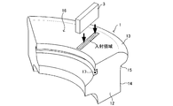
- FIG. 6 is a perspective view showing the arrangement position of the array probe in the ultrasonic flaw detection method according to the embodiment of the present invention.
- FIG. 7 is a plan view showing a propagation path viewed from the axial direction of the wheel.
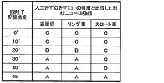
- FIG. 8 is a diagram comparing the intensity of shape echoes on the surface skin, ring groove and throat surface when the probe arrangement angle is changed with the intensity of flaw echoes on artificial flaws provided on the rim.
- FIG. 1 is a radial cross-sectional view of a wheel showing an example of a wheel to which the ultrasonic flaw detection method according to the present embodiment is applied.
- the wheel 1 is a railway wheel and includes a central boss portion 11 and a peripheral rim portion 12.
- the rim portion 12 includes a flange portion 13 protruding to the outer peripheral side and a tread surface 14 in contact with the rail over the entire outer periphery.
- a portion interposed between the surface of the flange portion 13 and the tread surface 14 is referred to as a throat surface 15.
- the side surface on the side where the flange portion 13 is formed among the two side surfaces perpendicular to the axis of the wheel 1 is referred to as a flange-side rim surface 16.
- FIG. 1 shows the wheel 1 having the ring groove 17 as an example.
- the ring groove 17 is formed over the entire circumference in the circumferential direction from the inner surface of the rim portion 12 toward the radially outer side.
- FIG. 2 is a diagram for explaining an example of an ultrasonic flaw detection apparatus used in the ultrasonic flaw detection method according to the present embodiment.
- FIG. 2A is a configuration diagram of an ultrasonic flaw detector
- FIG. 2B is a configuration diagram of an array probe included in the ultrasonic flaw detector.
- the ultrasonic flaw detector 2 includes an array probe 3 disposed to face the flange side rim surface 16 of the wheel 1. Also, an array flaw detector 4 that transmits a transmission / reception control signal to the array probe 3 and amplifies a signal received from the array probe 3, and various parameter settings for the array flaw detector 4 are performed.
- a personal computer 5 having a function of receiving a signal from the array flaw detector 4 and creating an image of an A scope, a B scope, etc., and a control panel 7 for giving a rotation signal or the like to a rotation drive unit 6 to be described later And.
- the wheel 1 having a horizontal axis is supported from the lower side, and the rotation drive unit 6 that rotates the wheel 1 to perform the flaw detection on the entire circumference of the rim 12 and the wheel 1 and the array probe 3 are submerged.
- the array probe 3 includes a plurality of transducers 32 arranged in a straight line, and the surface of the array probe 3 to which ultrasonic waves are transmitted from the transducer 32 is referred to as a transducer surface 31.
- the transducer surface 31 of the array probe 3 is disposed so as to face the flange-side rim surface 16, and the tank 1 and the array probe 3 are immersed in the tank 8 as a contact medium. Add water. Oil or the like can also be used as the contact medium.
- the flaw detection conditions such as the intensity and scanning speed of ultrasonic waves transmitted from the array probe 3 are set in the personal computer 5, and the flaw detection conditions are converted into transmission / reception control signals by the array flaw detector 4 and transmitted to the array probe 3. Is done.
- the array probe 3 transmits ultrasonic waves to the rim portion 12 from the flange side rim surface 16 and transmits a signal corresponding to the echo received from the rim portion 12 to the array flaw detector 4.
- the array flaw detector 4 amplifies the signal received from the array probe 3 and transmits it to the personal computer 5, and the personal computer 5 displays images of the A scope, B scope, and the like. Further, a rotation signal is transmitted from the personal computer 5 to the rotation drive unit 6 via the control panel 7 to rotate the wheel 1. In this way, the rim portion 12 is flaw-detected in the circumferential direction.
- Transmission / reception of ultrasonic waves from the array probe 3 is performed by, for example, linear scanning (in linear scanning, several transducers 32 constituting the array probe 3 are set as one transmission unit, and ultrasonic waves are transmitted in one transmission unit. Is transmitted so that the ultrasonic waves from each transducer 32 are parallel to each other, or the transmission timing of each transducer 32 is shifted to concentrate the ultrasonic waves from each transducer 32 at one point.
- the array probe 3 is controlled by the transmission / reception control signal from the array flaw detector 4 so that the transmission units are sequentially shifted along the arrangement direction of the transducers 32.
- a method of parallel scanning of ultrasonic waves) and steering scan is a transmission unit of several transducers 32 constituting the array probe 3 and transmits ultrasonic waves in the transmission unit.
- the ultrasonic waves from each transducer 32 are transmitted in parallel with each other, or the transmission timing of each transducer 32 is shifted to concentrate the ultrasonic waves from each transducer 32 at one point. In this state, scanning is performed by changing the emission angle.
- the ultrasonic flaw detection method is characterized by the arrangement position of the array probe 3, and the arrangement position of the array probe 3 will be described.
- the transducer arrangement direction (longitudinal direction) of the array probe 3 when viewed from the axial direction is generally set so that an area through which an incident region passes when a flaw is detected by rotating a wheel is increased.
- the angle formed by the radial direction of the wheel (probe arrangement angle) was set to 0 °.
- FIG. 3 is a perspective view showing the arrangement position of the array probe in the conventional ultrasonic flaw detection method. In FIG. 3, only a part of the wheel 1 is shown. The incident region extends in the radial direction.
- FIG. 4 shows the B scope when flaw detection is performed with the probe arrangement angle set to 0 °.
- 4A is a photograph of the B scope
- FIG. 4B is a schematic diagram of the B scope.
- the horizontal axis represents the ultrasonic wave propagation time
- the vertical axis represents the ultrasonic wave scanning position. That is, the horizontal axis indicates the depth position from the flange-side rim surface 16, and the vertical axis indicates the radial position on the flange-side rim surface 16.
- the shape of the rim portion is indicated by a solid line.
- the rim portion 12 that images the B scope is provided with an artificial scratch having a flat bottom hole of 1 mm ⁇ perpendicularly toward the flange side rim surface 16 from the rim surface opposite to the flange side rim surface 16.
- the distance from the flange side rim surface 16 to the tip of the artificial flaw is 50 mm, and the echo (flaw echo) at the tip of the artificial flaw is detected by the B scope.
- a surface echo appears in the vicinity of the flange-side rim surface 16.
- a shape echo of the surface skin appears from the flange side rim surface 16 to a position deeper than the surface echo.
- a shape echo of the ring groove 17 appears at a position deeper than the ring groove 17 and a position deeper than the ring groove 17, and a shape echo of the throat surface 15 appears near the throat surface 15. If the artificial flaw is provided at a location where the shape echo of the ring groove 17 and the throat surface 15 appears, the strength of the flaw echo of the artificial flaw is compared with the strength of the shape echo of the ring groove 17 and the throat surface 15. In the case of equal or less, detection of the artificial flaw is difficult.
- FIG. 5 is a diagram illustrating a propagation path of the ultrasonic wave transmitted to the flange-side rim surface 16.
- FIG. 5A is a radial sectional view showing a propagation path viewed from the circumferential direction of the wheel 1
- FIG. 5B is a plan view showing the propagation path viewed from the axial direction of the wheel 1.
- the surface skin of the flange side rim surface 16 of the wheel is composed of a large number of fine cutting traces by a cutting tool blade during surface processing, and the cutting traces are formed in a circle around the wheel axis.
- the ultrasonic wave U1 transmitted obliquely from the transducer 32 toward the radially inner side with respect to the entire flange-side rim surface 16 is reflected radially inward if the flange-side rim surface 16 is flat.
- the flange side rim surface 16 has a large number of cut trace irregularities in the radial direction. Accordingly, a part of the ultrasonic wave is reflected by the flange-side rim surface 16 and returned to the vibrator 32 when viewed from the circumferential direction of the wheel 1.
- a part of the ultrasonic wave U2 transmitted obliquely from the vibrator 32 toward the outer side in the radial direction with respect to the entire flange-side rim surface 16 is also seen on the flange-side rim surface 16 when viewed from the circumferential direction of the wheel 1. Reflected and returned to the vibrator 32.
- the propagation path seen from the axial direction of the wheel 1 will be described with reference to FIG. In FIG. 5B, only a few cutting traces are drawn for convenience. Since the probe arrangement angle is 0 °, the ultrasonic wave U3 from the vibrator 32 is reflected perpendicularly to the cutting trace and returns to the vibrator 32. If the flange-side rim surface 16 has irregularities in the circumferential direction, the flange-side rim surface 16 is dispersed and reflected in the circumferential direction by the flange-side rim surface 16, but the flange-side rim surface 16 is circumferentially formed by a cutting tool blade during surface processing. Since it is a cut surface of a smooth surface, many ultrasonic waves return to the vibrator 32 when viewed from the axial direction of the wheel 1.
- a part of the ultrasonic waves transmitted from the array probe 3 returns to the array probe 3 when viewed from both the circumferential direction and the axial direction of the wheel 1. Therefore, a part of the ultrasonic wave transmitted from the array probe 3 is reflected on the surface skin and returns to the array probe 3 and appears on the B scope as a shape echo of the surface skin.
- the surface skin shape echoes returning to the array probe 3 in this way are not echoes of ultrasonic waves transmitted / received from the transducer 32 in a direction substantially perpendicular to the entire flange-side rim surface 16 but obliquely.
- the surface echo of the flange side rim surface 16 (the surface echo of the flange side rim surface 16 is formed by the ultrasonic waves transmitted and received in a direction substantially perpendicular to the entire flange side rim surface 16. ) Has a longer propagation time than Therefore, in the B scope, the shape echo of the surface skin appears up to a position deeper than the surface echo of the flange-side rim surface 16. For this reason, it becomes difficult to detect a flaw at the position of the B scope where the surface skin shape echo appears.
- the probe arrangement angle is 0 °
- the ultrasonic waves U4 and U5 from the transducer 32 are reflected perpendicularly to the throat surface 15 and the ring groove 17 as shown in FIG. Come back. Therefore, shape echoes of the throat surface 15 and the ring groove 17 appear in the B scope. For this reason, it becomes difficult to detect a flaw at the position of the B scope where the shape echoes of the throat surface 15 and the ring groove 17 appear.
- FIG. 6 is a perspective view showing the arrangement position of the array probe.
- the wheel 1 shows only a part.
- the incident area is oblique to the radial direction.
- FIG. 7 is a plan view showing the propagation path of the ultrasonic wave as viewed from the axial direction of the wheel 1.
- the propagation path of the ultrasonic wave seen from the circumferential direction of the wheel 1 when the probe arrangement angle is larger than 0 ° is the same as that when the probe arrangement angle is 0 °, and FIG.
- the ultrasonic wave transmitted from the transducer 32 toward the radially inner side and the radially outer side is reflected by the flange-side rim surface 16 and returns to the transducer 32.
- the ultrasonic wave U7 transmitted from the transducer 32 toward the outside in the radial direction is difficult to return to the transducer 32 after being reflected by the cutting trace.
- the probe arrangement angle is larger than 0 °, the ultrasonic wave U8 transmitted from the transducer 32 toward the throat surface 15 is difficult to return to the transducer 32 after being reflected by the throat surface 15. Similarly, the ultrasonic wave U9 transmitted from the vibrator 32 toward the ring groove 17 is difficult to return to the vibrator 32 after being reflected by the ring groove 17.
- FIG. 8 is a diagram comparing the strength of the shape echoes of the surface skin, the ring groove 17 and the throat surface 15 with the strength of the flaw echoes of the artificial flaw provided on the rim portion 12 when the probe arrangement angle is changed. It is.
- the array probe 3 used had 128 transducers, a transducer pitch of 1 mm, a simultaneous excitation number of 24, and an array probe length of 128 mm. Moreover, the width
- the artificial flaw is an artificial flaw having a flat bottom hole of 1 mm ⁇ perpendicularly from the rim surface opposite to the flange-side rim surface 16 toward the flange-side rim surface 16.
- the flange side rim surface 16 was provided at a position of 50 mm.
- the sensitivity of the transducer 32 was adjusted so that the intensity of the flaw echo of the artificial flaw was the same at any probe arrangement angle.
- A, surface skin, and ring groove when the surface skin of the flange side rim surface 16, the strength of the shape echoes from the ring groove 17 and the throat surface 15 are sufficiently lower than the strength of the flaw echo of the artificial flaw. No.
- the probe placement angle may be set as follows. Although four types of array probes 3 having different widths were used, all of the array probes 3 had the same result.
- the probe arrangement angle is preferably 20 to 45 °, more preferably 30 to 45 °.
- the probe arrangement angle is preferably 20 to 45 °, more preferably 30 to 45 °.
- the probe arrangement angle is preferably 40 to 45 °, more preferably 45 °.
- FIG. 8 does not show the result at a probe arrangement angle larger than 45 °, but at the probe arrangement angle larger than 45 ° and smaller than 90 °, the shape from the surface skin, the ring groove 17 and the throat surface 15 is not shown.
- the intensity of the echo was sufficiently lower than that of the artificial flaw.
- the probe arrangement angle is set to 60 ° or less so that the area through which the incident region passes becomes 1 ⁇ 2 or more compared to when the probe arrangement angle is 0 °.
- the probe arrangement angle may be 70 ° or less or 80 ° or less.
- the probe arrangement angle is set to 20 to 60 °. More preferably, the probe arrangement angle is set to 30 to 60 °. This makes it difficult for surface skin shape echoes to return to the array probe. Therefore, the intensity of the shape echo of the surface skin is lower than that of the flaw echo from the artificial flaw, and the flaw echo from the vicinity of the flange side rim surface 16 can be easily identified from the shape echo of the surface skin.
- the probe arrangement angle is set to 20 to 60 °. More preferably, the probe arrangement angle is set to 30 to 60 °. As a result, the intensity of the shape echo of the ring groove 17 becomes lower than that of the flaw echo from the artificial flaw. Thereby, it becomes easy to distinguish the flaw echo from the ring groove 17 vicinity from the shape echo of the ring groove 17. Accordingly, in order to detect flaws in two different areas near the surface skin and near the ring groove 17, the shape echoes of the surface skin and the ring groove 17 can be detected only by setting the probe arrangement angle to 20 to 60 °. The intensity can be lowered, and a single array probe can detect flaws with high accuracy.
- the probe arrangement angle is set to 40 to 60 °. More preferably, the probe arrangement angle is set to 45 to 60 °. As a result, the intensity of the shape echo of the throat surface 15 is lower than that of the flaw echo from the artificial flaw. Thereby, it becomes easy to identify the flaw echo from the vicinity of the throat surface 15 from the shape echo of the throat surface 15. Therefore, in a wheel having no ring groove 17, the probe arrangement angle is set to 40 to 60 ° in order to detect flaws in two different regions near the flange-side rim surface 16 and the throat surface 15.
- the intensity of the shape echoes on the surface skin and the throat surface 15 can be reduced, and the flaws can be detected with high precision by one array probe.
- the probe arrangement angle is set to 40 to 60 °. As long as it is set to 1, the intensity of the shape echoes of the surface skin of the flange side rim surface 16, the ring groove 17 and the throat surface 15 can be lowered, and the flaws can be detected with high precision by one array probe.
Landscapes
- Physics & Mathematics (AREA)
- Health & Medical Sciences (AREA)
- Life Sciences & Earth Sciences (AREA)
- Chemical & Material Sciences (AREA)
- Analytical Chemistry (AREA)
- Biochemistry (AREA)
- General Health & Medical Sciences (AREA)
- General Physics & Mathematics (AREA)
- Immunology (AREA)
- Pathology (AREA)
- Acoustics & Sound (AREA)
- Investigating Or Analyzing Materials By The Use Of Ultrasonic Waves (AREA)
Abstract
Priority Applications (7)
| Application Number | Priority Date | Filing Date | Title |
|---|---|---|---|
| AU2012274664A AU2012274664B2 (en) | 2011-06-22 | 2012-06-05 | Ultrasonic testing method of wheel. |
| CN201280040501.1A CN103765205B (zh) | 2011-06-22 | 2012-06-05 | 车轮的超声波探伤方法 |
| US14/128,649 US9341598B2 (en) | 2011-06-22 | 2012-06-05 | Ultrasonic testing method of wheel |
| JP2013521518A JP5601603B2 (ja) | 2011-06-22 | 2012-06-05 | 車輪の超音波探傷方法 |
| EP12802416.3A EP2728346B1 (fr) | 2011-06-22 | 2012-06-05 | Procédé de détection par ultrasons de défaut de roue de véhicule |
| CA2839662A CA2839662C (fr) | 2011-06-22 | 2012-06-05 | Procede de detection par ultrasons de defaut de roue de vehicule |
| ES12802416.3T ES2657550T3 (es) | 2011-06-22 | 2012-06-05 | Método de detección por ultrasonidos de defectos en rueda de vehículo |
Applications Claiming Priority (2)
| Application Number | Priority Date | Filing Date | Title |
|---|---|---|---|
| JP2011138534 | 2011-06-22 | ||
| JP2011-138534 | 2011-06-22 |
Publications (1)
| Publication Number | Publication Date |
|---|---|
| WO2012176612A1 true WO2012176612A1 (fr) | 2012-12-27 |
Family
ID=47422452
Family Applications (1)
| Application Number | Title | Priority Date | Filing Date |
|---|---|---|---|
| PCT/JP2012/064433 Ceased WO2012176612A1 (fr) | 2011-06-22 | 2012-06-05 | Procédé de détection par ultrasons de défaut de roue de véhicule |
Country Status (8)
| Country | Link |
|---|---|
| US (1) | US9341598B2 (fr) |
| EP (1) | EP2728346B1 (fr) |
| JP (1) | JP5601603B2 (fr) |
| CN (1) | CN103765205B (fr) |
| AU (1) | AU2012274664B2 (fr) |
| CA (1) | CA2839662C (fr) |
| ES (1) | ES2657550T3 (fr) |
| WO (1) | WO2012176612A1 (fr) |
Cited By (1)
| Publication number | Priority date | Publication date | Assignee | Title |
|---|---|---|---|---|
| CN105158336A (zh) * | 2015-10-09 | 2015-12-16 | 中国石油天然气第一建设公司 | 一种多功能超声相控阵管道环焊缝检测设备 |
Families Citing this family (10)
| Publication number | Priority date | Publication date | Assignee | Title |
|---|---|---|---|---|
| US9664652B2 (en) * | 2014-10-30 | 2017-05-30 | The Boeing Company | Non-destructive ultrasonic inspection apparatus, systems, and methods |
| CN105092702B (zh) * | 2015-07-31 | 2019-03-22 | 中车大同电力机车有限公司 | 超声波检测样轴方法及装置 |
| CN105606708B (zh) * | 2015-11-10 | 2019-04-09 | 南京拓控信息科技有限公司 | 一种列车车轮便携式探伤系统的检测方法 |
| CN105675721A (zh) * | 2016-01-29 | 2016-06-15 | 上海应用技术学院 | 一种超声成像检测装置及系统 |
| CN108469470B (zh) * | 2017-12-11 | 2024-03-29 | 马鞍山钢铁股份有限公司 | 一种火车车轮自动线超声波探伤用样轮 |
| JP6797853B2 (ja) * | 2018-03-14 | 2020-12-09 | 株式会社東芝 | 検知システム、ホイール及び検知方法 |
| CN109725064A (zh) * | 2019-03-01 | 2019-05-07 | 北京双河理声自动化检测技术有限公司 | 一种轮辋超声检测装置及检测方法 |
| US11280765B2 (en) * | 2020-03-31 | 2022-03-22 | Baker Hughes Oilfield Operations Llc | Methods and devices for ultrasonic nondestructive testing devices |
| CN112964792B (zh) * | 2021-02-01 | 2024-06-25 | 太原重工轨道交通设备有限公司 | 用于车轮轮缘的超声波检测校准试块及检测方法 |
| CN116908296A (zh) * | 2023-06-30 | 2023-10-20 | 宝武集团马钢轨交材料科技有限公司 | 一种基于相控阵超声波的火车车轮探伤方法 |
Citations (3)
| Publication number | Priority date | Publication date | Assignee | Title |
|---|---|---|---|---|
| JP2003004709A (ja) * | 2001-06-22 | 2003-01-08 | Sumitomo Metal Ind Ltd | 車輪の超音波検査方法及び装置 |
| JP2005207811A (ja) * | 2004-01-21 | 2005-08-04 | Denso Corp | 形状変化検出装置 |
| JP2007093311A (ja) | 2005-09-28 | 2007-04-12 | Jfe Steel Kk | 超音波探傷方法 |
Family Cites Families (9)
| Publication number | Priority date | Publication date | Assignee | Title |
|---|---|---|---|---|
| GB2144545B (en) * | 1983-08-04 | 1986-12-03 | British Gas Corp | A wheel probe |
| US4898034A (en) * | 1988-08-23 | 1990-02-06 | The United States Of America As Represented By The Department Of Energy | High temperature ultrasonic testing of materials for internal flaws |
| US5497662A (en) * | 1993-09-07 | 1996-03-12 | General Electric Company | Method and apparatus for measuring and controlling refracted angle of ultrasonic waves |
| JP3808513B2 (ja) | 1994-03-01 | 2006-08-16 | 株式会社東芝 | 超音波探傷方法及び装置 |
| DE59905207D1 (de) * | 1998-07-22 | 2003-05-28 | Fraunhofer Ges Forschung | Ultraschall-prüfeinrichtung |
| US7017414B2 (en) * | 2003-07-30 | 2006-03-28 | General Electric Company | Ultrasonic inspection method and system therefor |
| CN101639463B (zh) * | 2009-09-03 | 2011-01-19 | 北京主导时代科技有限公司 | 一种基于相控阵探头的机车车辆车轮缺陷检测装置 |
| CN201548525U (zh) * | 2009-09-14 | 2010-08-11 | 成都主导科技有限责任公司 | 一种列车车轮轮辐缺陷的超声波检测设备 |
| CN201697897U (zh) * | 2010-06-10 | 2011-01-05 | 北京新联铁科技发展有限公司 | 轨道车辆不落轮超声波车轮自动探伤机 |
-
2012
- 2012-06-05 JP JP2013521518A patent/JP5601603B2/ja active Active
- 2012-06-05 US US14/128,649 patent/US9341598B2/en active Active
- 2012-06-05 CN CN201280040501.1A patent/CN103765205B/zh active Active
- 2012-06-05 WO PCT/JP2012/064433 patent/WO2012176612A1/fr not_active Ceased
- 2012-06-05 AU AU2012274664A patent/AU2012274664B2/en active Active
- 2012-06-05 CA CA2839662A patent/CA2839662C/fr active Active
- 2012-06-05 ES ES12802416.3T patent/ES2657550T3/es active Active
- 2012-06-05 EP EP12802416.3A patent/EP2728346B1/fr active Active
Patent Citations (3)
| Publication number | Priority date | Publication date | Assignee | Title |
|---|---|---|---|---|
| JP2003004709A (ja) * | 2001-06-22 | 2003-01-08 | Sumitomo Metal Ind Ltd | 車輪の超音波検査方法及び装置 |
| JP2005207811A (ja) * | 2004-01-21 | 2005-08-04 | Denso Corp | 形状変化検出装置 |
| JP2007093311A (ja) | 2005-09-28 | 2007-04-12 | Jfe Steel Kk | 超音波探傷方法 |
Non-Patent Citations (1)
| Title |
|---|
| See also references of EP2728346A4 |
Cited By (2)
| Publication number | Priority date | Publication date | Assignee | Title |
|---|---|---|---|---|
| CN105158336A (zh) * | 2015-10-09 | 2015-12-16 | 中国石油天然气第一建设公司 | 一种多功能超声相控阵管道环焊缝检测设备 |
| CN105158336B (zh) * | 2015-10-09 | 2017-12-22 | 中国石油天然气第一建设有限公司 | 一种多功能超声相控阵管道环焊缝检测设备 |
Also Published As
| Publication number | Publication date |
|---|---|
| ES2657550T3 (es) | 2018-03-05 |
| AU2012274664B2 (en) | 2015-03-05 |
| JP5601603B2 (ja) | 2014-10-08 |
| AU2012274664A1 (en) | 2014-01-30 |
| CA2839662C (fr) | 2016-08-16 |
| EP2728346A1 (fr) | 2014-05-07 |
| US9341598B2 (en) | 2016-05-17 |
| EP2728346B1 (fr) | 2017-10-25 |
| CN103765205A (zh) | 2014-04-30 |
| JPWO2012176612A1 (ja) | 2015-02-23 |
| EP2728346A4 (fr) | 2015-03-18 |
| CA2839662A1 (fr) | 2012-12-27 |
| CN103765205B (zh) | 2016-04-20 |
| US20140224024A1 (en) | 2014-08-14 |
Similar Documents
| Publication | Publication Date | Title |
|---|---|---|
| JP5601603B2 (ja) | 車輪の超音波探傷方法 | |
| US10768148B2 (en) | Method for detecting flaw in train wheel with single ultrasonic pulse and testing device therefor | |
| US8161818B2 (en) | Device for detecting a flaw in a component | |
| WO2007058391A1 (fr) | Appareil ultrasonique de detection de defauts et procede ultrasonique de detection de defauts dans des canalisations | |
| JP2010266463A (ja) | 超音波探触子、超音波探傷装置、超音波探傷方法及び継目無管の製造方法 | |
| WO2020250378A1 (fr) | Procédé et dispositif de détection de défauts par ultrasons, ligne d'équipement et procédé de fabrication de matériau en acier, et procédé d'assurance qualité pour matériau en acier | |
| CN101666781B (zh) | 一种机车车辆车轮轮辐缺陷超声波检测装置 | |
| CN107817296A (zh) | 一种环件自动化多频阵列超声无损检测装置及方法 | |
| US9921186B2 (en) | Method and device for the non-destructive inspection of a rotationally symmetric workpiece having sections with difference diameters | |
| JP5325394B2 (ja) | 軸部材の超音波探傷方法、超音波探傷装置および超音波探傷システム | |
| CN201548525U (zh) | 一种列车车轮轮辐缺陷的超声波检测设备 | |
| WO2020250379A1 (fr) | Procédé de détection de défauts par ultrasons, dispositif de détection de défauts par ultrasons, ligne d'équipement de fabrication de matériau en acier, procédé de fabrication de matériau en acier et procédé d'assurance qualité de matériau en acier | |
| JP6513771B2 (ja) | 丸棒材の超音波探傷装置 | |
| JP6992678B2 (ja) | 超音波探傷方法、超音波探傷装置、鋼材の製造設備列、鋼材の製造方法、及び鋼材の品質保証方法 | |
| JP2007101329A (ja) | 溶接部溶け込み深さ探査方法及び溶接部溶け込み深さ探査装置 | |
| JP6733650B2 (ja) | 超音波探傷方法、超音波探傷装置、鋼材の製造設備列、及び鋼材の製造方法 | |
| JP2009058238A (ja) | 欠陥検査方法および装置 | |
| RU2394235C1 (ru) | Способ ультразвукового контроля сварных соединений труб малого диаметра | |
| JP2016090245A (ja) | 超音波探傷装置 | |
| CN105143873A (zh) | 借助于超声波的用于具有逐段改变的直径的旋转对称加工件的近表面无损检查的方法和装置 | |
| JP2007198822A (ja) | 車輪用軸受外輪の転走面焼入れ深さ測定方法 | |
| JP4943016B2 (ja) | 超音波による焼入深さ測定方法および測定装置 | |
| JP2003322642A (ja) | 板波超音波探傷方法及びその装置 | |
| CN119846079A (zh) | 一种动车组轮辋轮辐超声检测探头布局方法 | |
| JP2019090682A (ja) | 超音波探傷方法 |
Legal Events
| Date | Code | Title | Description |
|---|---|---|---|
| WWE | Wipo information: entry into national phase |
Ref document number: 201280040501.1 Country of ref document: CN |
|
| 121 | Ep: the epo has been informed by wipo that ep was designated in this application |
Ref document number: 12802416 Country of ref document: EP Kind code of ref document: A1 |
|
| ENP | Entry into the national phase |
Ref document number: 2013521518 Country of ref document: JP Kind code of ref document: A |
|
| ENP | Entry into the national phase |
Ref document number: 2839662 Country of ref document: CA |
|
| NENP | Non-entry into the national phase |
Ref country code: DE |
|
| REEP | Request for entry into the european phase |
Ref document number: 2012802416 Country of ref document: EP |
|
| WWE | Wipo information: entry into national phase |
Ref document number: 2012802416 Country of ref document: EP |
|
| ENP | Entry into the national phase |
Ref document number: 2012274664 Country of ref document: AU Date of ref document: 20120605 Kind code of ref document: A |
|
| WWE | Wipo information: entry into national phase |
Ref document number: 14128649 Country of ref document: US |