WO2012176724A1 - 溶接トーチ - Google Patents
溶接トーチ Download PDFInfo
- Publication number
- WO2012176724A1 WO2012176724A1 PCT/JP2012/065481 JP2012065481W WO2012176724A1 WO 2012176724 A1 WO2012176724 A1 WO 2012176724A1 JP 2012065481 W JP2012065481 W JP 2012065481W WO 2012176724 A1 WO2012176724 A1 WO 2012176724A1
- Authority
- WO
- WIPO (PCT)
- Prior art keywords
- collet
- electrode rod
- welding torch
- electrode
- length direction
- Prior art date
- Legal status (The legal status is an assumption and is not a legal conclusion. Google has not performed a legal analysis and makes no representation as to the accuracy of the status listed.)
- Ceased
Links
Images






Classifications
-
- B—PERFORMING OPERATIONS; TRANSPORTING
- B23—MACHINE TOOLS; METAL-WORKING NOT OTHERWISE PROVIDED FOR
- B23K—SOLDERING OR UNSOLDERING; WELDING; CLADDING OR PLATING BY SOLDERING OR WELDING; CUTTING BY APPLYING HEAT LOCALLY, e.g. FLAME CUTTING; WORKING BY LASER BEAM
- B23K9/00—Arc welding or cutting
- B23K9/24—Features related to electrodes
- B23K9/28—Supporting devices for electrodes
- B23K9/29—Supporting devices adapted for making use of shielding means
- B23K9/291—Supporting devices adapted for making use of shielding means the shielding means being a gas
- B23K9/296—Supporting devices adapted for making use of shielding means the shielding means being a gas using non-consumable electrodes
-
- B—PERFORMING OPERATIONS; TRANSPORTING
- B23—MACHINE TOOLS; METAL-WORKING NOT OTHERWISE PROVIDED FOR
- B23K—SOLDERING OR UNSOLDERING; WELDING; CLADDING OR PLATING BY SOLDERING OR WELDING; CUTTING BY APPLYING HEAT LOCALLY, e.g. FLAME CUTTING; WORKING BY LASER BEAM
- B23K35/00—Rods, electrodes, materials, or media, for use in soldering, welding, or cutting
- B23K35/02—Rods, electrodes, materials, or media, for use in soldering, welding, or cutting characterised by mechanical features, e.g. shape
-
- B—PERFORMING OPERATIONS; TRANSPORTING
- B23—MACHINE TOOLS; METAL-WORKING NOT OTHERWISE PROVIDED FOR
- B23K—SOLDERING OR UNSOLDERING; WELDING; CLADDING OR PLATING BY SOLDERING OR WELDING; CUTTING BY APPLYING HEAT LOCALLY, e.g. FLAME CUTTING; WORKING BY LASER BEAM
- B23K35/00—Rods, electrodes, materials, or media, for use in soldering, welding, or cutting
- B23K35/02—Rods, electrodes, materials, or media, for use in soldering, welding, or cutting characterised by mechanical features, e.g. shape
- B23K35/0255—Rods, electrodes, materials, or media, for use in soldering, welding, or cutting characterised by mechanical features, e.g. shape for use in welding
-
- B—PERFORMING OPERATIONS; TRANSPORTING
- B23—MACHINE TOOLS; METAL-WORKING NOT OTHERWISE PROVIDED FOR
- B23K—SOLDERING OR UNSOLDERING; WELDING; CLADDING OR PLATING BY SOLDERING OR WELDING; CUTTING BY APPLYING HEAT LOCALLY, e.g. FLAME CUTTING; WORKING BY LASER BEAM
- B23K35/00—Rods, electrodes, materials, or media, for use in soldering, welding, or cutting
- B23K35/02—Rods, electrodes, materials, or media, for use in soldering, welding, or cutting characterised by mechanical features, e.g. shape
- B23K35/0255—Rods, electrodes, materials, or media, for use in soldering, welding, or cutting characterised by mechanical features, e.g. shape for use in welding
- B23K35/0261—Rods, electrodes or wires
-
- B—PERFORMING OPERATIONS; TRANSPORTING
- B23—MACHINE TOOLS; METAL-WORKING NOT OTHERWISE PROVIDED FOR
- B23K—SOLDERING OR UNSOLDERING; WELDING; CLADDING OR PLATING BY SOLDERING OR WELDING; CUTTING BY APPLYING HEAT LOCALLY, e.g. FLAME CUTTING; WORKING BY LASER BEAM
- B23K35/00—Rods, electrodes, materials, or media, for use in soldering, welding, or cutting
- B23K35/02—Rods, electrodes, materials, or media, for use in soldering, welding, or cutting characterised by mechanical features, e.g. shape
- B23K35/0255—Rods, electrodes, materials, or media, for use in soldering, welding, or cutting characterised by mechanical features, e.g. shape for use in welding
- B23K35/0261—Rods, electrodes or wires
- B23K35/0277—Rods, electrodes or wires of non-circular cross-section
-
- B—PERFORMING OPERATIONS; TRANSPORTING
- B23—MACHINE TOOLS; METAL-WORKING NOT OTHERWISE PROVIDED FOR
- B23K—SOLDERING OR UNSOLDERING; WELDING; CLADDING OR PLATING BY SOLDERING OR WELDING; CUTTING BY APPLYING HEAT LOCALLY, e.g. FLAME CUTTING; WORKING BY LASER BEAM
- B23K35/00—Rods, electrodes, materials, or media, for use in soldering, welding, or cutting
- B23K35/02—Rods, electrodes, materials, or media, for use in soldering, welding, or cutting characterised by mechanical features, e.g. shape
- B23K35/0255—Rods, electrodes, materials, or media, for use in soldering, welding, or cutting characterised by mechanical features, e.g. shape for use in welding
- B23K35/0294—Consumable guides
-
- B—PERFORMING OPERATIONS; TRANSPORTING
- B23—MACHINE TOOLS; METAL-WORKING NOT OTHERWISE PROVIDED FOR
- B23K—SOLDERING OR UNSOLDERING; WELDING; CLADDING OR PLATING BY SOLDERING OR WELDING; CUTTING BY APPLYING HEAT LOCALLY, e.g. FLAME CUTTING; WORKING BY LASER BEAM
- B23K9/00—Arc welding or cutting
- B23K9/16—Arc welding or cutting making use of shielding gas
- B23K9/167—Arc welding or cutting making use of shielding gas and of a non-consumable electrode
- B23K9/1675—Arc welding or cutting making use of shielding gas and of a non-consumable electrode making use of several electrodes
Definitions
- the present invention relates to a welding torch.
- This application claims priority based on Japanese Patent Application No. 2011-138411 filed in Japan on June 22, 2011, the contents of which are incorporated herein by reference.
- Patent Document 1 discloses a multi-electrode welding torch capable of realizing high-speed welding in TIG welding.
- this multi-electrode welding torch is configured to include a pair of electrode rods arranged to face each other with an insulating material interposed therebetween, and a collet for fixing these electrode rods.
- this multi-electrode welding torch is configured to include a pair of electrode rods arranged to face each other with an insulating material interposed therebetween, and a collet for fixing these electrode rods.
- the electrode rod is formed into a thin plate shape and the tip of the electrode rod is sharpened. This shape is very advantageous in that it can weld a narrow groove.
- the electrode rod is formed of a tungsten-based material, it is difficult to process and it is difficult to form a thin plate. For this reason, the manufacturing cost of an electrode stick will increase. Therefore, it is desired to manufacture a multi-electrode type welding torch in which a cheaper electrode rod can be used.
- the electrode rod from a round rod having a circular cross section made of a tungsten-based material.
- a round bar having a circular cross section made of a tungsten-based material is generally sold and can be manufactured at low cost since a manufacturing technique has been established. Therefore, it is possible to manufacture the electrode rod at a low cost.
- the electrode bar when the electrode bar is formed from a round bar having a circular cross section, the electrode bar has an arcuate curved region in at least a part of the cross sectional shape. Power is supplied to the electrode rod through a metal member called a collet.
- a metal member called a collet.
- the collet is compared with a conventional plate shape having a wide flat surface. There is a possibility that the contact area between the electrode and the electrode rod is reduced, and the power feeding becomes unstable. More specifically, when the electrode has a plate shape, it is possible to contact the collet having the same plate shape with the surface, so that a wide contact area can be secured.
- the electrode when the electrode is a rod having a circular cross section, the contact area is reduced because the electrode contacts the collet having a plate shape with a line.
- the present invention has been made in view of the above-described problems, and in a multi-electrode welding torch, when an electrode bar having a curved region in cross-sectional shape is used, the contact area between the collet and the electrode bar is increased, The object is to stably supply power to the electrode rod.
- the present invention adopts the following configuration as means for solving the above-described problems.
- a first aspect according to the present invention is a welding torch comprising a plurality of electrode rods arranged via an insulating material, and a collet that contacts the electrode rods and conducts to the electrode rods, the electrode rods comprising:
- the arcuate curved region is formed in at least a part of the cross-sectional shape orthogonal to the length direction, and the collet is fitted with the electrode rod and the curved region as viewed from the length direction of the electrode rod.
- a configuration is adopted in which a plurality of grooves are provided in contact with the inner wall surface.
- the second aspect according to the present invention employs a configuration in which, in the first aspect, a notch is provided at the tip of the collet facing the tip side of the electrode rod. In this case, it is desirable that the notch is provided in a portion of the tip of the collet that does not contact the electrode rod.
- the third aspect includes a collet support member that is fixedly disposed with respect to the electrode rod, and the collet is tiltable with respect to the electrode rod. Further, a configuration in which the collet supporting member is supported by the above is adopted.
- the collet is supported by the collet support member so as to be displaceable in a direction perpendicular to the length direction of the electrode rod.
- the configuration is adopted.
- the fifth aspect according to the present invention employs a configuration in which, in any of the first to fourth aspects, the shape of the groove as viewed from the length direction of the electrode rod is a trapezoid.
- the protrusion protruding from the inner wall surface of the groove and the fitting that is provided on the electrode rod and fits the protrusion A configuration including a hole is employed.
- the collet includes a groove portion in which the electrode bar is fitted and the inner wall surface is in contact with a plurality of locations in the curved surface region when viewed from the length direction of the electrode bar. For this reason, when viewed from the length direction of the electrode rod, at least two contact portions between the collet and the electrode rod can be secured. Therefore, according to the present invention, in a multi-electrode welding torch, the contact area between the collet and the electrode rod in the case of using an electrode rod having a curved surface in the cross-sectional shape is increased, and the power supply to the electrode rod is stabilized. Can be performed.
- FIG. 1B is a cross-sectional view taken along line NN in FIG. 1A. It is the figure which looked at the collet with which the welding torch in one embodiment of the present invention is provided from the side opposite to an electrode bar. It is a side view of the collet shown in FIG. 2A. It is the figure which looked at the collet shown in Drawing 2A from the electrode stick side. It is the figure which looked at the collet shown in Drawing 2A from the back end side. It is sectional drawing which extracted and illustrated the collet, collet base, etc. with which the welding torch in one Embodiment of this invention is provided.
- FIG. 1B is a cross-sectional view taken along line NN in FIG. 1A. It is the figure which looked at the collet with which the welding torch in one embodiment of the present invention is provided from the side opposite to an electrode bar. It is a side view of the collet shown in FIG. 2A. It is the figure which looked at the collet shown in Drawing 2A from the electrode stick
- 3B is a sectional view taken along line MM in FIG. 3A. It is a top view of the collet base with which the welding torch in one embodiment of the present invention is provided. It is a schematic diagram which shows the modification of the welding torch in one Embodiment of this invention. It is a schematic diagram which shows the modification of the welding torch in one Embodiment of this invention. It is a schematic diagram which shows the modification of the welding torch in one Embodiment of this invention. It is a schematic diagram which shows the modification of the welding torch in one Embodiment of this invention.
- FIG. 1A and FIG. 1B are schematic configuration diagrams of a welding torch 1 of this embodiment used for TIG welding.
- 1A is a cross-sectional view taken along a plane along the central axis L
- FIG. 1B is a cross-sectional view taken along line NN in FIG. 1A.
- the welding torch 1 includes an electrode rod 2, an insulating material 3, a collet 4, a casing 5, and a gas supply unit 6.
- the electrode rod 2 is supplied with an electric current from a power supply device (not shown) and generates an arc with the welding material.
- the two electrode rods 2 are arranged to face each other with the insulating material 3 interposed therebetween. That is, the welding torch 1 of the present embodiment includes a pair of electrode rods 2 arranged with the insulating material 3 interposed therebetween.
- the electrode bar 2 is formed of a round bar having a circular cross section made of a tungsten-based material. As shown in FIG. 1A, the tip end side of the electrode rod 2 is pointed so that its leading edge is located on the central axis L side.
- the electrode rod 2 is cut so that a part of the periphery as viewed from the tip side is cut by a plane parallel to the axis of the electrode rod 2.
- the electrode rod 2 includes a flat surface portion 2a as a processing portion formed by cutting.
- the electrode rod 2 is disposed so that the planar portion 2a faces the insulating material 3 and the planar portion 2a is in contact with the insulating material 3.
- such an electrode rod 2 has a shape having an arc-shaped curved region R in at least a part of a cross-sectional shape orthogonal to the length direction.
- the insulating material 3 is disposed between the two electrode rods 2 and prevents the electrode rods 2 from coming into contact with each other and short-circuiting. As shown in FIG. 1B, the insulating material 3 is shaped so that the cross section is I-shaped. A portion of the insulating material 3 that contacts the flat portion 2 a of the electrode rod 2 is a flat portion 3 a that is in surface contact with the flat portion 2 a of the electrode rod 2.
- the collet 4 is provided for each of the electrode rods 2 and conducts current supplied from a power supply device (not shown) to the electrode rods 2. Each collet 4 is disposed outside the electrode rod 2 when viewed from the tip end side of the electrode rod 2.
- FIG. 2A to 2D are diagrams showing the entire structure of the collet 4.
- FIG. 2A is a view of the collet 4 viewed from the side opposite to the electrode rod 2
- FIG. 2B is a side view of the collet 4
- FIG. 2C is a view of the collet 4 viewed from the electrode rod 2 side
- 2D is a view of the collet 4 as viewed from the rear end side (the side opposite to the front end of the electrode rod 2).
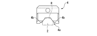
- the collet 4 is formed along the length direction of the electrode rod 2, and as shown in FIGS. 2C and 2D, a groove portion in which the shape viewed from the end face side of the electrode rod 2 is a trapezoidal shape. 4a.
- the groove 4a is configured such that when the electrode rod 2 is fitted to the collet 4, the curved surface region R of the electrode rod 2 contacts the inner wall surface 4b.
- the width and depth of the groove 4a are set so that the inner wall surface 4b of the groove 4a contacts the curved surface region R of the electrode rod 2 at two locations.
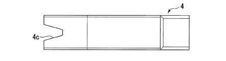
- a portion 4c is provided.
- the notch 4 c is provided in a portion of the groove 4 a that does not come into contact with the electrode rod 2 when the electrode rod 2 is fitted to the collet 4.
- the collet 4 is supported so as to be tiltable with respect to the electrode rod 2 around the end opposite to the tip. For this reason, the tip of the collet 4 is the place that makes the most contact with the electrode rod 2.
- the notch part 4c in the part which does not contact the electrode stick
- FIG. 4 is a plan view of the collet base 7.
- the collet base 7 is fastened by screws 9 to an adapter 8 fixed to the casing 5, whereby the position of the collet base 7 with respect to the electrode rod 2 is determined.
- the collet base 7 is provided with a long hole 7a that is long in the radial direction.
- a bolt 10 that is relatively movable in the long hole 7a along the longitudinal direction of the long hole 7a is inserted into the long hole 7a. Is fixed.
- the end of collet 4 (the end opposite to the tip) is arranged with a slight gap S with respect to collet base 7.
- the collet 4 can tilt about the end opposite to the tip provided with the notch 4c.
- the collet 4 is fixed to a bolt 10 that can move in a long hole 7 a that is long in the radial direction of the collet base 7, the collet 4 can be displaced in a direction perpendicular to the length direction of the electrode rod 2.
- the casing 5 fixes the collet 4 by covering the collet 4 and a part of the electrode rod 2 on which the collet 4 is not disposed outside from the periphery, and contacting the outer peripheral surface of the collet 4.
- the gas supply unit 6 is disposed on the distal end side of the welding torch 1 and supplies a gas for forming an arc toward the distal end of the electrode rod 2.
- the collet 4 is fitted with the electrode rod 2 and at a plurality of locations in the curved surface region R as viewed from the length direction of the electrode rod 2 (in the present embodiment, 2 places) and the groove part 4a which the inner wall surface 4b contacts is provided. That is, at least two contact points between the collet 4 and the electrode rod 2 are ensured when viewed from the length direction of the electrode rod 2. Therefore, according to the welding torch 1 of the present embodiment, the contact area between the collet 4 and the electrode rod 2 when the electrode rod 2 having the curved surface region R in the cross-sectional shape is used in the multi-electrode type welding torch is increased. The power supply to the electrode rod 2 can be performed stably.
- the notch part 4c is provided in the front-end
- FIG. For this reason, as described above, the tip of the collet 4 is apparently long, and the number of places that reliably contact the electrode rod 2 can be increased. Therefore, it becomes possible to stably supply power to the electrode rod 2 more reliably.
- the collet 4 is supported by the collet base 7 so as to be tiltable with respect to the electrode rod 2. For this reason, when assembling the welding torch 1 of the present embodiment, the collet 4 can be tilted and brought into contact with the electrode rod 2 reliably.
- the contact area between the electrode rod 2 and the collet 4 decreases.
- the collet 4 is supported by the collet base 7 so as to be displaceable in a direction orthogonal to the length direction of the electrode rod 2.
- the tilt angle of the collet 4 with respect to the electrode rod 2 can be prevented from becoming too large, and the contact area between the electrode rod 2 and the collet 4 is sufficiently wide. It becomes possible to secure with.
- the shape of the groove 4a is a trapezoidal shape. For this reason, it becomes possible to ensure two places of contact between the electrode rod 2 and the collet 4 while suppressing the depth of the groove 4a.
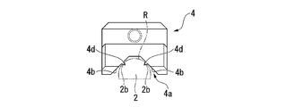
- the inner wall surface 4b of the groove 4a may be a curved surface that bulges toward the electrode rod 2 side.
- the inner wall surface 4b of the groove 4a can be strongly pressed against the curved surface region R of the electrode rod 2, and a wider contact area between the electrode rod 2 and the collet 4 can be secured. Is possible.
- region R of the electrode rod 2, and the projection part 4d fits. It is also possible to adopt. In this configuration, the protrusion 4d is fitted in the fitting hole 2b, whereby the rotation of the electrode rod 2 with respect to the collet 4 can be prevented.
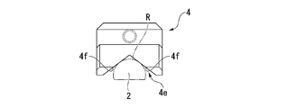
- FIG. 5C it is possible to adopt a configuration including a triangular groove 4e instead of the trapezoidal groove 4a. Even in such a case, as shown in FIG. 5C, two contact points between the inner wall surface 4f and the electrode rod 2 can be secured.
- the present invention is not limited to this, and it is possible to adopt a configuration in which the number of contact points between the electrode rod 2 and the collet 4 is further increased.
- the contact area between the collet and the electrode rod can be increased, and the power supply to the electrode rod can be stably performed.
Landscapes
- Engineering & Computer Science (AREA)
- Mechanical Engineering (AREA)
- Physics & Mathematics (AREA)
- Plasma & Fusion (AREA)
- Arc Welding In General (AREA)
Abstract
Description
本願は、2011年6月22日に日本に出願された特願2011-138311号に基づき優先権を主張し、その内容をここに援用する。
この多電極方式の溶接トーチは、特許文献1に示すように、絶縁材を挟んで対向配置される一対の電極棒と、これらの電極棒を固定するコレット等とを備えて構成されている。
そして、特許文献1においては、より狭い開先の溶接を行うために、電極棒を薄い板状とすると共に、電極棒の先端を尖らせた形状を採用している。
ところが、電極棒は、タングステン系の材料で形成されているので、加工が難しく、薄い板状とすることが困難である。このため、電極棒の製造コストが増大してしまう。
よって、より安価な電極棒が使用できる多電極方式の溶接トーチを製造することが望まれる。
電極棒にはコレットと呼ばれる金属部材を介して給電が行われているが、電極棒が曲面領域を有する場合には、電極が平面を広く有する従来の板形状である場合と比較して、コレットと電極棒との接触面積が減少し、給電が不安定となる可能性がある。
より詳細に説明すると、電極が板形状である場合には、同じく板形状とされたコレットに対して面と面で接触させることができるため広い接触面積を確保することができる。一方、電極が断面円形の棒状である場合には、板形状とされたコレットに対して線で接触するため、接触面積が減少する。
この場合、上記コレットの先端のうち、上記電極棒と接触しない部分に上記切欠き部が設けられていることが望ましい。
このため、電極棒の長さ方向から見て、コレットと電極棒との接触箇所を最低2箇所確保することができる。
したがって、本発明によれば、多電極方式の溶接トーチにおいて、断面形状に曲面領域を有する電極棒を用いた場合におけるコレットと電極棒との接触面積を増大させ、電極棒への給電を安定的に行うことが可能となる。
図1A及び図1Bは、TIG溶接に用いられる本実施形態の溶接トーチ1の概略構成図である。なお、図1Aが中心軸Lに沿った面での断面図であり、図1Bが図1AのN-N線に沿った断面図である。
本実施形態の溶接トーチ1では、絶縁材3を挟んで2つの電極棒2が対向して配置されている。つまり、本実施形態の溶接トーチ1は、絶縁材3を挟んで配置される一対の電極棒2を備えている。
そして、電極棒2の先端側は、図1Aに示すように、その最先端が中心軸L側に位置するよう尖っている。
また、電極棒2は、平面部位2aを絶縁材3側に向け、平面部位2aが絶縁材3と接触するように配置されている。
このような電極棒2は、図1Bに示すように、長さ方向と直交する断面形状の少なくとも一部に円弧状の曲面領域Rを有する形状とされている。
図1Bに示すように、絶縁材3は、断面がI字状となるような形状とされている。
そして、絶縁材3の、電極棒2の平面部位2aに当接する部位が、電極棒2の平面部位2aと面接触する平面部位3aとされている。
この溝部4aは、図2Dに示すように、電極棒2がコレット4に嵌合された際に、電極棒2の曲面領域Rが内壁面4bに当接するよう構成されている。
そして、本実施形態において溝部4aの幅及び深さは、溝部4aの内壁面4bが2箇所で電極棒2の曲面領域Rと当接するように設定されている。
後に詳説するが、コレット4は、先端と反対側の端を中心として電極棒2に対して傾動可能に支持されている。このため、コレット4の先端が最も電極棒2と確実に接触する箇所となっている。そして、このようなコレット4の先端のうち、電極棒2と接触しない部分に切欠き部4cを設けることによって、切欠き部4cを設けない場合と比較して、コレット4の先端が見かけ上長くなり、電極棒2と確実に接触する箇所を増大させることができる。
図3A及び図3Bは、コレット4及びコレットベース7等を抜き出して図示した断面図である。なお、図3Bは図3AのM-M線に沿った断面図である。また、図4は、コレットベース7の平面図である。
また、コレット4は、コレットベース7の半径方向に長い長孔7a内を移動可能なボルト10に固定されているため、電極棒2の長さ方向と直交する方向に変位可能とされている。
以上のような本実施形態の溶接トーチ1によれば、コレット4が、電極棒2が嵌合されると共に電極棒2の長さ方向から見て曲面領域Rの複数箇所(本実施形態においては2箇所)と内壁面4bが接触する溝部4aを備える。
つまり、電極棒2の長さ方向から見て、コレット4と電極棒2との接触箇所が最低2箇所確保される。
したがって、本実施形態の溶接トーチ1によれば、多電極方式の溶接トーチにおいて、断面形状に曲面領域Rを有する電極棒2を用いた場合におけるコレット4と電極棒2との接触面積を増大させ、電極棒2への給電を安定的に行うことが可能となる。
このため、上述のように、コレット4の先端が見かけ上長くなり、電極棒2と確実に接触する箇所を増大させることができる。よって、より確実に電極棒2への給電を安定的に行うことが可能となる。
このため、本実施形態の溶接トーチ1を組み立てる際に、コレット4を傾動させて電極棒2に対して確実に接触させることができる。
これに対して、本実施形態の溶接トーチ1においては、コレット4が、電極棒2の長さ方向と直交する方向に変位可能にコレットベース7に支持されている。
このため、本実施形態の溶接トーチ1によれば、電極棒2に対するコレット4の傾動角度が大きくなり過ぎることを防止することができ、電極棒2とコレット4との接触面積を十分な広さで確保することが可能となる。
このような構成とすることによって、溝部4aの内壁面4bを電極棒2の曲面領域Rに対して強く押し当てることが可能となり、電極棒2とコレット4との接触面積をより広く確保することが可能となる。
この構成では、突起部4dが嵌合穴2bに嵌合することにより、コレット4に対する電極棒2の回転を防止することができる。
このような場合であっても、図5Cに示すように、内壁面4fと電極棒2との接触箇所を2箇所確保することができる。
しかしながら、本発明はこれに限定されるものではなく、電極棒2とコレット4との接触箇所がさらに多数となる構成を採用することも可能である。
Claims (7)
- 絶縁材を介して配置される複数の電極棒と、この電極棒に当接すると共に前記電極棒に導電するコレットとを備える溶接トーチであって、
前記電極棒は、長さ方向と直交する断面形状の少なくとも一部に円弧状の曲面領域を有する形状とされ、
前記コレットは、前記電極棒が嵌合されると共に前記電極棒の長さ方向から見て前記曲面領域の複数箇所と内壁面が接触する溝部を備える溶接トーチ。 - 前記電極棒の先端側を向く前記コレットの先端に切欠き部が設けられている請求項1に記載の溶接トーチ。
- 前記コレットの先端のうち、前記電極棒と接触しない部分に前記切欠き部が設けられている請求項2に記載の溶接トーチ。
- 前記電極棒に対する位置が固定して配置されるコレット支持部材を備え、
前記コレットは、前記電極棒に対して傾動可能に前記コレット支持部材に支持されている請求項1に記載の溶接トーチ。 - 前記コレットは、前記電極棒の長さ方向と直交する方向に変位可能に前記コレット支持部材に支持されている請求項1に記載の溶接トーチ。
- 前記電極棒の長さ方向から見た前記溝部の形状が台形形状とされている請求項1に記載の溶接トーチ。
- 前記溝部の内壁面から突出する突起部と、前記電極棒に設けられると共に前記突起部が嵌合する嵌合穴とを備える請求項1に記載の溶接トーチ。
Priority Applications (4)
| Application Number | Priority Date | Filing Date | Title |
|---|---|---|---|
| ES12803182.0T ES2614870T3 (es) | 2011-06-22 | 2012-06-18 | Soplete de soldadura |
| US14/123,674 US9278405B2 (en) | 2011-06-22 | 2012-06-18 | Welding torch |
| JP2013521571A JP5720782B2 (ja) | 2011-06-22 | 2012-06-18 | 溶接トーチ |
| EP12803182.0A EP2724809B1 (en) | 2011-06-22 | 2012-06-18 | Welding torch |
Applications Claiming Priority (2)
| Application Number | Priority Date | Filing Date | Title |
|---|---|---|---|
| JP2011138311 | 2011-06-22 | ||
| JP2011-138311 | 2011-06-22 |
Publications (1)
| Publication Number | Publication Date |
|---|---|
| WO2012176724A1 true WO2012176724A1 (ja) | 2012-12-27 |
Family
ID=47422561
Family Applications (1)
| Application Number | Title | Priority Date | Filing Date |
|---|---|---|---|
| PCT/JP2012/065481 Ceased WO2012176724A1 (ja) | 2011-06-22 | 2012-06-18 | 溶接トーチ |
Country Status (5)
| Country | Link |
|---|---|
| US (1) | US9278405B2 (ja) |
| EP (1) | EP2724809B1 (ja) |
| JP (1) | JP5720782B2 (ja) |
| ES (1) | ES2614870T3 (ja) |
| WO (1) | WO2012176724A1 (ja) |
Cited By (1)
| Publication number | Priority date | Publication date | Assignee | Title |
|---|---|---|---|---|
| US20230123460A1 (en) * | 2021-10-20 | 2023-04-20 | Sungwoo Hitech Co., Ltd. | Cap tip assembly for spot welding |
Citations (6)
| Publication number | Priority date | Publication date | Assignee | Title |
|---|---|---|---|---|
| JPS5360537U (ja) * | 1976-10-26 | 1978-05-23 | ||
| JPS57194788U (ja) * | 1981-06-02 | 1982-12-10 | ||
| JPH08206839A (ja) * | 1995-02-07 | 1996-08-13 | Masao Miki | 溶接トーチ |
| JPH09295154A (ja) * | 1996-04-26 | 1997-11-18 | Ishikawajima Harima Heavy Ind Co Ltd | 多電極溶接トーチ |
| JP2000071074A (ja) * | 1998-08-28 | 2000-03-07 | Daihen Corp | Tigアーク溶接ロボット |
| JP2000094137A (ja) | 1998-09-22 | 2000-04-04 | Ishikawajima Harima Heavy Ind Co Ltd | Tig溶接トーチ |
Family Cites Families (12)
| Publication number | Priority date | Publication date | Assignee | Title |
|---|---|---|---|---|
| GB778963A (en) | 1954-10-22 | 1957-07-17 | Gen Electric Co Ltd | Improvements in or relating to electric welding apparatus |
| FR2361447A1 (fr) | 1976-08-12 | 1978-03-10 | Oreal | Composes colorants constitues de polymeres cationiques hydrosolubles et compositions tinctoriales les contenant |
| JPS5341321U (ja) * | 1976-09-13 | 1978-04-10 | ||
| JPS5360537A (en) | 1976-11-10 | 1978-05-31 | Ardac Inc | Tester for identifying adaptability of certificate |
| BE891916A (fr) | 1981-01-28 | 1982-05-17 | Biotechnolog Forschung Gmbh | Procede d'obtention de cellules hybrides productrices d'un anticorps specifique et procede de production d'anticorps, cellules hybrides et anticorps specifiques ainsi obtenues |
| JP3027902B2 (ja) | 1994-02-21 | 2000-04-04 | 石川島播磨重工業株式会社 | 多電極溶接ト−チ及び多電極溶接装置 |
| JP3620136B2 (ja) | 1996-01-25 | 2005-02-16 | 石川島播磨重工業株式会社 | 溶接トーチ |
| JP3767101B2 (ja) | 1997-06-27 | 2006-04-19 | 石川島播磨重工業株式会社 | 溶接トーチの電極固定装置 |
| US6683279B1 (en) * | 2001-12-27 | 2004-01-27 | Delford A. Moerke | Twin MIG welding apparatus |
| US7176412B2 (en) * | 2004-03-31 | 2007-02-13 | Tregaskiss Ltd | Taper locking features between components of a welding device |
| US20110297657A1 (en) | 2010-02-04 | 2011-12-08 | Taiko Engineering Co., Ltd. | Contact tip for supplying welding electric power and welding torch using the contact tip |
| US9789560B2 (en) * | 2010-05-12 | 2017-10-17 | Jesse Rogers | Arc welding torch having a variable electrode receiver |
-
2012
- 2012-06-18 US US14/123,674 patent/US9278405B2/en not_active Expired - Fee Related
- 2012-06-18 WO PCT/JP2012/065481 patent/WO2012176724A1/ja not_active Ceased
- 2012-06-18 JP JP2013521571A patent/JP5720782B2/ja active Active
- 2012-06-18 ES ES12803182.0T patent/ES2614870T3/es active Active
- 2012-06-18 EP EP12803182.0A patent/EP2724809B1/en not_active Not-in-force
Patent Citations (6)
| Publication number | Priority date | Publication date | Assignee | Title |
|---|---|---|---|---|
| JPS5360537U (ja) * | 1976-10-26 | 1978-05-23 | ||
| JPS57194788U (ja) * | 1981-06-02 | 1982-12-10 | ||
| JPH08206839A (ja) * | 1995-02-07 | 1996-08-13 | Masao Miki | 溶接トーチ |
| JPH09295154A (ja) * | 1996-04-26 | 1997-11-18 | Ishikawajima Harima Heavy Ind Co Ltd | 多電極溶接トーチ |
| JP2000071074A (ja) * | 1998-08-28 | 2000-03-07 | Daihen Corp | Tigアーク溶接ロボット |
| JP2000094137A (ja) | 1998-09-22 | 2000-04-04 | Ishikawajima Harima Heavy Ind Co Ltd | Tig溶接トーチ |
Non-Patent Citations (1)
| Title |
|---|
| See also references of EP2724809A4 * |
Cited By (1)
| Publication number | Priority date | Publication date | Assignee | Title |
|---|---|---|---|---|
| US20230123460A1 (en) * | 2021-10-20 | 2023-04-20 | Sungwoo Hitech Co., Ltd. | Cap tip assembly for spot welding |
Also Published As
| Publication number | Publication date |
|---|---|
| EP2724809B1 (en) | 2016-12-14 |
| EP2724809A4 (en) | 2015-05-27 |
| US20140091068A1 (en) | 2014-04-03 |
| JPWO2012176724A1 (ja) | 2015-02-23 |
| JP5720782B2 (ja) | 2015-05-20 |
| ES2614870T3 (es) | 2017-06-02 |
| US9278405B2 (en) | 2016-03-08 |
| EP2724809A1 (en) | 2014-04-30 |
Similar Documents
| Publication | Publication Date | Title |
|---|---|---|
| CN103358335B (zh) | 理发器 | |
| JP6243476B2 (ja) | スパークプラグ及びその製造方法 | |
| JP4683673B1 (ja) | 溶接給電用コンタクトチップ及びそれを用いた溶接トーチ | |
| US20140064863A1 (en) | Tip dresser | |
| JP6327256B2 (ja) | スポット溶接用電極およびこれを用いた溶接装置ならびに溶接方法 | |
| JP5720782B2 (ja) | 溶接トーチ | |
| JP2015112632A (ja) | 溶接装置 | |
| JPWO2016103917A1 (ja) | 溶接用コンタクトチップ | |
| JP2017520409A (ja) | プラズマ切断用トーチアセンブリ及びその摩耗部品の用途 | |
| JP2012240049A (ja) | 溶接トーチ | |
| JP2006272472A (ja) | スローアウェイ式ドリル | |
| JP3603575B2 (ja) | 溶接用給電チップ | |
| US9321122B2 (en) | Spot welding tip for a spot welding machine | |
| JP2015037814A (ja) | 歯切り用回転切削工具 | |
| JP3700405B2 (ja) | Tig溶接トーチ | |
| CN209380055U (zh) | 一种双丝窄间隙焊枪 | |
| JP6726139B2 (ja) | 部材の製造方法 | |
| EP3247009B1 (en) | Method for manufacturing tubular metal shell including ground electrode bar for spark plug, and method for manufacturing spark plug | |
| JP3196346U (ja) | 溶接ガン用アダプタ、これを有する溶接ガンアーム並びに溶接ガン主体、及び前記溶接ガン用アダプタを有する溶接ガン | |
| JP2014113447A (ja) | 立体構造シートカッター | |
| JP3700406B2 (ja) | 横向き溶接用tig溶接トーチ | |
| JP2017177128A (ja) | 摩擦攪拌接合方法 | |
| JP5013440B2 (ja) | カーボンブラシ | |
| CN119255884A (zh) | 焊接用导电嘴 | |
| KR101928585B1 (ko) | Tig 용접 장치의 토치 구조 |
Legal Events
| Date | Code | Title | Description |
|---|---|---|---|
| 121 | Ep: the epo has been informed by wipo that ep was designated in this application |
Ref document number: 12803182 Country of ref document: EP Kind code of ref document: A1 |
|
| ENP | Entry into the national phase |
Ref document number: 2013521571 Country of ref document: JP Kind code of ref document: A |
|
| WWE | Wipo information: entry into national phase |
Ref document number: 14123674 Country of ref document: US |
|
| REEP | Request for entry into the european phase |
Ref document number: 2012803182 Country of ref document: EP |
|
| WWE | Wipo information: entry into national phase |
Ref document number: 2012803182 Country of ref document: EP |
|
| NENP | Non-entry into the national phase |
Ref country code: DE |