WO2012176805A1 - Dispositif de conditionnement d'air encastrable - Google Patents
Dispositif de conditionnement d'air encastrable Download PDFInfo
- Publication number
- WO2012176805A1 WO2012176805A1 PCT/JP2012/065747 JP2012065747W WO2012176805A1 WO 2012176805 A1 WO2012176805 A1 WO 2012176805A1 JP 2012065747 W JP2012065747 W JP 2012065747W WO 2012176805 A1 WO2012176805 A1 WO 2012176805A1
- Authority
- WO
- WIPO (PCT)
- Prior art keywords
- heat exchanger
- heat exchange
- unit
- blower
- built
- Prior art date
- Legal status (The legal status is an assumption and is not a legal conclusion. Google has not performed a legal analysis and makes no representation as to the accuracy of the status listed.)
- Ceased
Links
Images


Classifications
-
- F—MECHANICAL ENGINEERING; LIGHTING; HEATING; WEAPONS; BLASTING
- F24—HEATING; RANGES; VENTILATING
- F24F—AIR-CONDITIONING; AIR-HUMIDIFICATION; VENTILATION; USE OF AIR CURRENTS FOR SCREENING
- F24F1/00—Room units for air-conditioning, e.g. separate or self-contained units or units receiving primary air from a central station
- F24F1/0007—Indoor units, e.g. fan coil units
- F24F1/0059—Indoor units, e.g. fan coil units characterised by heat exchangers
- F24F1/0063—Indoor units, e.g. fan coil units characterised by heat exchangers by the mounting or arrangement of the heat exchangers
-
- F—MECHANICAL ENGINEERING; LIGHTING; HEATING; WEAPONS; BLASTING
- F24—HEATING; RANGES; VENTILATING
- F24F—AIR-CONDITIONING; AIR-HUMIDIFICATION; VENTILATION; USE OF AIR CURRENTS FOR SCREENING
- F24F13/00—Details common to, or for air-conditioning, air-humidification, ventilation or use of air currents for screening
- F24F13/22—Means for preventing condensation or evacuating condensate
-
- F—MECHANICAL ENGINEERING; LIGHTING; HEATING; WEAPONS; BLASTING
- F24—HEATING; RANGES; VENTILATING
- F24F—AIR-CONDITIONING; AIR-HUMIDIFICATION; VENTILATION; USE OF AIR CURRENTS FOR SCREENING
- F24F1/00—Room units for air-conditioning, e.g. separate or self-contained units or units receiving primary air from a central station
- F24F1/0007—Indoor units, e.g. fan coil units
- F24F1/0043—Indoor units, e.g. fan coil units characterised by mounting arrangements
- F24F1/0047—Indoor units, e.g. fan coil units characterised by mounting arrangements mounted in the ceiling or at the ceiling
-
- F—MECHANICAL ENGINEERING; LIGHTING; HEATING; WEAPONS; BLASTING
- F24—HEATING; RANGES; VENTILATING
- F24F—AIR-CONDITIONING; AIR-HUMIDIFICATION; VENTILATION; USE OF AIR CURRENTS FOR SCREENING
- F24F13/00—Details common to, or for air-conditioning, air-humidification, ventilation or use of air currents for screening
- F24F13/30—Arrangement or mounting of heat-exchangers
-
- F—MECHANICAL ENGINEERING; LIGHTING; HEATING; WEAPONS; BLASTING
- F28—HEAT EXCHANGE IN GENERAL
- F28D—HEAT-EXCHANGE APPARATUS, NOT PROVIDED FOR IN ANOTHER SUBCLASS, IN WHICH THE HEAT-EXCHANGE MEDIA DO NOT COME INTO DIRECT CONTACT
- F28D1/00—Heat-exchange apparatus having stationary conduit assemblies for one heat-exchange medium only, the media being in contact with different sides of the conduit wall, in which the other heat-exchange medium is a large body of fluid, e.g. domestic or motor car radiators
- F28D1/02—Heat-exchange apparatus having stationary conduit assemblies for one heat-exchange medium only, the media being in contact with different sides of the conduit wall, in which the other heat-exchange medium is a large body of fluid, e.g. domestic or motor car radiators with heat-exchange conduits immersed in the body of fluid
- F28D1/04—Heat-exchange apparatus having stationary conduit assemblies for one heat-exchange medium only, the media being in contact with different sides of the conduit wall, in which the other heat-exchange medium is a large body of fluid, e.g. domestic or motor car radiators with heat-exchange conduits immersed in the body of fluid with tubular conduits
- F28D1/0408—Multi-circuit heat exchangers, e.g. integrating different heat exchange sections in the same unit or heat exchangers for more than two fluids
-
- F—MECHANICAL ENGINEERING; LIGHTING; HEATING; WEAPONS; BLASTING
- F28—HEAT EXCHANGE IN GENERAL
- F28D—HEAT-EXCHANGE APPARATUS, NOT PROVIDED FOR IN ANOTHER SUBCLASS, IN WHICH THE HEAT-EXCHANGE MEDIA DO NOT COME INTO DIRECT CONTACT
- F28D1/00—Heat-exchange apparatus having stationary conduit assemblies for one heat-exchange medium only, the media being in contact with different sides of the conduit wall, in which the other heat-exchange medium is a large body of fluid, e.g. domestic or motor car radiators
- F28D1/02—Heat-exchange apparatus having stationary conduit assemblies for one heat-exchange medium only, the media being in contact with different sides of the conduit wall, in which the other heat-exchange medium is a large body of fluid, e.g. domestic or motor car radiators with heat-exchange conduits immersed in the body of fluid
- F28D2001/0253—Particular components
- F28D2001/026—Cores
- F28D2001/0266—Particular core assemblies, e.g. having different orientations or having different geometric features
-
- F—MECHANICAL ENGINEERING; LIGHTING; HEATING; WEAPONS; BLASTING
- F28—HEAT EXCHANGE IN GENERAL
- F28D—HEAT-EXCHANGE APPARATUS, NOT PROVIDED FOR IN ANOTHER SUBCLASS, IN WHICH THE HEAT-EXCHANGE MEDIA DO NOT COME INTO DIRECT CONTACT
- F28D21/00—Heat-exchange apparatus not covered by any of the groups F28D1/00 - F28D20/00
- F28D2021/0019—Other heat exchangers for particular applications; Heat exchange systems not otherwise provided for
- F28D2021/0068—Other heat exchangers for particular applications; Heat exchange systems not otherwise provided for for refrigerant cycles
Definitions
- the present invention relates to a built-in type air conditioner including an indoor unit installed on a ceiling of a building.
- a built-in type air conditioner including an indoor unit installed in a ceiling part such as a ceiling space of a building and an outdoor unit connected to the indoor unit via a refrigerant pipe is known.
- a compressor and an outdoor heat exchanger are accommodated in the outdoor unit, and an indoor heat exchanger and a blower are accommodated in the indoor unit.
- the compressor, the outdoor heat exchanger, and the indoor heat exchanger are connected by a refrigerant pipe to form a refrigerant circuit.
- coolant which flows through the inside of an indoor heat exchanger is blown out to the to-be-conditioned room via the blowing duct (for example, refer patent document 1).
- the indoor unit of a built-in type air conditioner is installed in a ceiling portion where installation space is limited.
- the two flat plate-like indoor heat exchangers (the upper heat exchanging portion and the lower heat exchanging portion) are viewed from the side. Some of them are connected so as to form a square shape.
- the upper heat exchanger is disposed at a position away from the drain pan. Therefore, there is a case where drain water from the upper heat exchanging part scatters from the U-shaped connecting part and blows out from the outlet by the air blown from the blower.
- the position or distance of the blower with respect to each part in the heat exchange surface becomes uneven. Therefore, there is a problem that differences in wind speed or temperature unevenness occur in each part in the heat exchange surface, and the heat exchange efficiency of the indoor heat exchanger cannot be made uniform.
- the fixing structure tends to be complicated.
- the fixture jumps out into the air passage of the indoor unit and becomes resistance to ventilation, or the secondary side chamber on the downstream side of the heat exchanger is separated from the primary side chamber on the upstream side and insulated.
- the number of parts increased, and the installation workability became worse.
- such a built-in type air conditioner is installed in the ceiling, once installed, it is difficult to remove the air conditioner for maintenance.
- a refrigerant pipe connected to the indoor heat exchanger or a drain pipe connected to a drain pump for draining drain water generated by the indoor heat exchanger and received by a drain pan is provided, for example, as a unit.
- the side plate of the case is passed through and pulled out from the unit body. For this reason, when removing the indoor heat exchanger from the unit main body during maintenance of the indoor heat exchanger, etc., these refrigerant pipes and drain pipes are connected to the inside of the unit main body from the indoor heat exchanger or drain pump in a narrow ceiling space. It was necessary to perform the work of removing the indoor heat exchanger from the unit body after removing or removing the unit body from the ceiling space together with the refrigerant piping, and the workability was poor.
- the present invention provides a built-in type air conditioner that solves the problems of the above-described conventional technology and can prevent the drain water from scattering from the heat exchanger while increasing the capacity of the indoor heat exchanger.
- the purpose is to do.
- Another object of the present invention is to provide a built-in type air conditioner that can make the heat exchange efficiency uniform while increasing the capacity of the indoor heat exchanger.
- It is another object of the present invention to provide a built-in type air conditioner that can solve the above-described problems of the prior art and can be mounted with an indoor heat exchanger with a simple structure and a small number of parts.
- Another object of the present invention is to provide a built-in type air conditioner that solves the problems of the conventional techniques described above and improves the maintainability of the indoor heat exchanger.
- the present invention comprises a unit main body configured to accommodate a heat exchanger and a blower, and the upper heat exchanging unit connected to the substantially square shape in a side view, and It includes a lower heat exchanging part, and is provided with a blower outlet of the blower so as to face the apex of the character, and in the unit body, the lower heat exchanging part and the upper heat exchanging part have the same width as the unit width. It is accommodated substantially fully, and the lower end of the upper heat exchanging portion is disposed on the lower heat exchanging portion at the apex of the substantially square shape.
- the upper heat exchanging portion is disposed closer to the blower than the upper end of the lower heat exchanging portion, the air outflow side surface of the upper heat exchanging portion, and the lower heat exchanging portion A step is provided between the upper end and the upper end.
- the present invention includes a unit main body configured to accommodate a heat exchanger and a blower, and the heat exchanger is connected to a substantially square shape in a side view. And a lower heat exchanging part, and the blower outlet of the blower is provided facing the apex of the character, and the lower heat exchanging part and the upper heat exchanging part have the same width in the unit body.
- the unit is accommodated in a substantially full width, and the heat exchange area of the lower heat exchange part is set larger than that of the upper heat exchange part.
- the present invention is characterized in that the heat exchange area of the upper heat exchange part is set to approximately 60% of the heat exchange area of the lower heat exchange part.
- the present invention divides the inside of the unit body into a blower chamber in which the blower is accommodated and a heat exchange chamber in which the heat exchanger is accommodated, and a drain pan that covers the entire bottom of the heat exchange chamber is provided, The lower end of the lower heat exchange part is placed on the drain pan.
- the inside of the unit body is partitioned by a partition plate into a heat exchange chamber that houses a heat exchanger and a blower chamber that houses a blower, and is sucked by the blower.
- the heat exchanger is fixed to the front plate and the top plate of the unit body at both ends of the heat exchanger, A resin-made fixing member for fixing inside the main body is provided.
- a vent hole through which the U-shaped tube of the heat exchanger passes is provided in a fixing member on one end side of both ends of the heat exchanger,
- the fixing member is provided with a U-shaped groove formed along the shape of the heat exchanger, and the refrigerant pipe of the heat exchanger is penetrated from the groove.
- the inside of the unit body is partitioned by a partition plate into a heat exchange chamber that houses a heat exchanger and a blower chamber that houses a blower, and is sucked by the blower.
- the heat exchanger is formed to be detachable from the opening on the lower surface of the unit body into the heat exchange chamber, and the unit body
- the refrigerant pipe of the heat exchanger protruding outward from the side plate is an inverted U-shaped groove that opens downward so that it can be inserted into the heat exchange chamber from the opening side integrally with the heat exchanger.
- a lid body having a U-shaped groove is attached to the side plate, and the refrigerant pipe can be held on the side plate by cooperation of the U-shaped groove of the lid body and the inverted U-shaped groove of the side plate. It is characterized by that.
- the present invention provides the above-described built-in type air conditioner, wherein the unit main body includes a drain pan that receives drain water generated by the heat exchanger, and drain water accumulated in the drain pan through the drain pipe.
- a drain pump for draining outside the unit main body is built in, and a pump unit in which the drain pump and the drain pipe are integrally combined is detachably disposed on the side plate of the unit main body on the side surface of the unit main body. It is characterized by being.
- the present invention is provided at both ends of the heat exchanger, is inserted into the heat exchange chamber from the opening side integrally with the heat exchanger, and is fixed to the front plate and the top plate of the unit body.
- the heat exchanger includes a resin fixing member that fixes the heat exchanger to the inside of the unit main body.
- the present invention provides the above built-in type air conditioner, wherein the heat exchanger includes an upper heat exchanging portion and a lower heat exchanging portion that are connected to each other in a side view in a side view, A blower outlet of the blower is provided so as to face each other.
- the present invention is characterized in that, in the built-in type air conditioner described above, the open side of the heat exchanger is opposed to the blower outlet of the blower.
- the present invention is characterized in that, in the built-in type air conditioner described above, the open side of the cross-section of the heat exchanger is directed to the downstream side of the heat exchanger.
- the built-in air conditioner in the built-in air conditioner described above, the built-in air conditioner according to any one of claims 1 to 8, wherein the blower is a centrifugal blower.
- resin fixing members for fixing the heat exchanger to the inside of the unit main body are provided at both ends of the heat exchanger and fixed to the front plate and the top plate of the unit main body.
- a heat exchanger is detachably formed in the heat exchange chamber from the opening on the lower surface of the unit main body, and the side plate of the unit main body protrudes outward from the side plate.
- the refrigerant pipe of the exchanger is provided with an inverted U-shaped groove that opens downward so that the refrigerant pipe can be inserted into the heat exchange chamber from the opening side integrally with the heat exchanger, and the lid having the U-shaped groove is disposed on the side plate. And the refrigerant pipe can be held on the side plate by the cooperation of the U-shaped groove of the lid and the inverted U-shaped groove of the side plate.
- tube can be hold
- the lid is removed from the side plate so that the heat exchanger and the refrigerant tube can be easily removed from the opening on the lower surface of the unit body without removing the refrigerant tube from the heat exchanger. Can be made. Therefore, the maintainability of the indoor heat exchanger can be improved.
- a pump unit in which a drain pump and a drain pipe are integrally combined is detachably disposed in the vicinity of the lid on the side surface of the unit main body.
- (A) is a front view of the other side fixing member
- (B) is a front view which shows the state which attached the other side fixing member to the indoor heat exchanger.
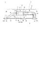
- a built-in type air conditioner 1 includes an outdoor unit (not shown) and an indoor unit 5 connected to the outdoor unit through a refrigerant pipe.
- the outdoor unit is installed outdoors such as on the rooftop of a building, exchanges heat with outdoor air, condenses the refrigerant during cooling operation and releases heat to the outside, and evaporates the refrigerant during heating operation. The heat is taken from outside air.
- the built-in type air conditioning apparatus 1 circulates this refrigerant between the outdoor unit and the indoor heat exchanger (heat exchanger) 60 of the indoor unit 5 to perform air conditioning of the conditioned room 2.
- the indoor unit 5 is disposed in a state of being hung in a ceiling space 34 between the ceiling 32 and the ceiling plate 33 of the building 31.
- the indoor unit 5 includes an indoor heat exchanger (heat exchanger) 60 and a blower 50 that blows air to the indoor heat exchanger 60.
- the indoor unit 5 includes a suction duct 53 and a blowout duct 54 that extend from the unit body 10 to the ceiling plate 33.
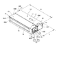
- the unit case 11 of the unit body 10 is formed in a substantially rectangular shape and includes a top plate 12, a bottom plate 13, side plates 14A and 14B, a suction side panel 15, and a blowout side panel (front plate) 16.
- a plurality of suspension fittings 41 are fixed to the side plates 14 ⁇ / b> A and 14 ⁇ / b> B of the unit case 11.
- Four suspension bolts 42 are suspended from the ceiling 32.
- the unit main body 10 is provided in a state in which the hanging metal fittings 41 are respectively fixed to the suspension bolts 42 and are hung in the ceiling back space 34.
- a detachable ceiling panel 35 is attached to the ceiling plate 33 at an appropriate position, particularly near the unit main body 10.
- Various maintenance of the indoor unit 5 can be performed from the conditioned room 2 side by removing the ceiling panel 35.
- the suction side panel 15 and the blowout side panel 16 are respectively disposed on a pair of opposing side surfaces of the unit case 11.
- the suction side panel 15 is arrange
- the blowout side panel 16 is arrange
- an air inlet 51 and an air inlet 52 are provided for communicating the interior of the conditioned room 2 with the ceiling space 34.
- the suction port 17 of the unit case 11 and the suction port 51 of the ceiling plate 33 are connected by a suction duct 53. Further, the air outlet 18 of the unit case 11 and the air supply port 52 of the ceiling plate 33 are connected by an air outlet duct 54.
- the indoor unit 5 sucks the air in the conditioned room 2 into the unit body 10 through the air inlet 51, the air inlet duct 53, and the air inlet 17 by driving the blower 50, and the air thus sucked into the indoor heat exchanger 60. Air is blown to exchange heat with the refrigerant flowing in the indoor heat exchanger 60.
- the conditioned air that has exchanged heat with the refrigerant flowing in the indoor heat exchanger 60 is supplied into the conditioned room 2 through the air outlet 18, the air outlet duct 54, and the air inlet 52. That is, the indoor unit 5 sucks the air in the conditioned room 2, exchanges heat with the refrigerant flowing in the indoor heat exchanger 60, and blows the conditioned air heat-exchanged with the refrigerant to the conditioned room 2 again.
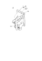
- One side surface of the unit case 11 is formed by a side plate 14A as shown in FIG.
- a maintenance panel 56, a pump unit 75, and a lid (pipe presser) 68 are detachably attached to the side plate 14A.
- the side plate 14A is provided with a maintenance opening (not shown) for performing maintenance of the electrical unit, and a maintenance panel 56 is attached to the side plate 14A so as to close the maintenance opening.
- the pump unit 75 includes a drain pump 78 that draws drain water from a drain pan 70 to be described later, and a fixture 79 for the drain pump 78.
- the side plate 14A is provided with a pump mounting opening 75A, and the drain pump 78 is accommodated in the unit case 11 through the pump mounting opening 75A.
- the fixture 79 fixes the drain pump 78 and is attached to the side plate 14A so as to close the pump attachment opening 75A.
- the side plate 14A is provided with a notch 68C through which the auxiliary refrigerant pipe (refrigerant pipe) 67 passes.
- the lid body 68 is configured to hold the auxiliary refrigerant pipe 67 penetrating the side plate 14A through the notch 68C and close the notch 68C.
- a drain pipe cutout 19 is provided by cutting out the side plate 14A so as to open downward.
- the drain pipe notch 19 is provided with a drain pipe presser 76 that is detachably fitted to the drain pipe notch 19.
- the drain pipe presser 76 is provided with a hole 76A (see FIG. 10) through which the drain drain pipe 77 passes.
- a drain drain pipe 77 connected to the drain pan 70 is provided so as to protrude from the hole 76A. For example, when drain water remaining in the drain pan 70 is discharged during maintenance of the unit body 10, the drain water can be discharged to the outside of the unit body 10 through the drain drain pipe 77.
- Screw holes 69 ⁇ / b> A and 69 ⁇ / b> A are formed in the blowout side panel 16 so as to be vertically arranged on both sides of the blowout outlet 18.
- Screw holes 69B and 69B are formed in the top plate 12 at substantially the same position in the unit width W direction of the screw holes 69A and the unit case 11.
- the screws 4 (see FIG. 5) for fixing the indoor heat exchanger 60 to the unit case 11 are screwed into the screw holes 69A and 69B.
- air sucked from the suction port 17 flows toward the blowout port 18 along the depth L direction of the unit case 11.
- the refrigerant circulating between the outdoor unit and the indoor unit 5 flows in the indoor heat exchanger 60 so as to be almost perpendicular to the air flow. That is, in the indoor heat exchanger 60, the refrigerant flows along the unit width W direction of the unit case 11.
- the bottom plate 13 is divided into two in the depth L direction of the unit case 11 into a blower chamber side bottom plate 13 ⁇ / b> B on the suction port 17 side and a heat exchange chamber side bottom plate 13 ⁇ / b> A on the outlet 18 side.
- Beads 71 and 72 extending in the width direction of the unit case 11 are formed at predetermined positions in the depth L direction of the unit case 11 on the heat exchange chamber side bottom plate 13A.
- the beads 71 and 72 may be a single continuous bead like the bead 71 or may be divided into a plurality of beads like the bead 72.
- the bottom plate 13 is formed from a thin plate member made of metal, and the beads 71 and 72 are formed by subjecting this plate member to press working or the like. Since the heat exchange chamber side bottom plate 13A includes the beads 71 and 72, the strength is improved. In addition, the length of each bead 71 and 72, the position to form, and the number to form can be suitably changed with respect to the magnitude
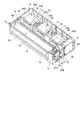
- FIG. 4 is a diagram in which the top plate 12 is removed from the unit case 11.
- the inside of the unit case 11 is a partition plate 55 provided substantially perpendicularly to the top plate 12 and the bottom plate 13, and houses the blower chamber R ⁇ b> 1 that houses the blower 50 and the indoor heat exchanger 60. It is divided into heat exchange chamber R2.
- the partition plate 55 is formed of a metal plate or the like, and blocks the air flow between the air blowing chamber R1 and the heat exchange chamber R2.
- the partition plate 55 is provided with an opening 55A, and an air blowing port (blow-out port) 50D of the blower 50 is connected to the opening 55A and exposed to the heat exchange chamber R2.
- a sirocco fan that is a centrifugal blower is used as the blower 50.
- the blower 50 is configured such that a cylindrical fan body 50A having a large number of blades is accommodated in a fan case 50B.
- the blower 50 includes a motor shaft 50C extending in the axial direction of the fan body 50A.
- the motor shaft 50 ⁇ / b> C is connected to the fan motor 20, and the fan main body 50 ⁇ / b> A is rotated by driving the fan motor 20.
- the number of blowers 50 accommodated in the blower chamber R1 can be appropriately changed according to the dimensions of the unit case 11 (the output capacity of the indoor unit 5).
- the blower chamber R1 is provided with a plurality of blowers 50 connected by a single motor shaft 50C, and the plurality of blowers 50 are similarly rotationally driven by the single fan motor 20.
- the structure provided with the fan motor 20 in each of the some air blower 50 may be sufficient.
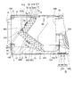
- the indoor heat exchanger 60 includes a flat plate-like upper heat exchange part 61 and a flat plate-like lower heat exchange part 62.
- the upper heat exchanging portion 61 and the lower heat exchanging portion 62 are combined and connected in a substantially square shape in a side view.
- the indoor heat exchanger 60 is configured by connecting the two plate-shaped heat exchange parts 61 and 62 in a substantially square shape in a side view. The height of the heat exchanger can be kept low and the heat exchange area can be increased compared to the case where the heat exchanger is arranged vertically.
- the upper heat exchanging portion 61 and the lower heat exchanging portion 62 are both fin-and-tube heat exchangers, and are arranged with a space between the pair of tube plates extending in the ventilation direction and the tube plates.
- the tubes are arranged in a plurality of rows in the front and rear (three rows in the present embodiment) and in a plurality of stages in the vertical direction, and are connected as one refrigerant pipe by a U-shaped portion (U vent) provided at the end of each tube.
- the upper heat exchanging portion 61 has an upper end portion 61 ⁇ / b> C extending to the lower surface side of the top plate 12.
- the lower heat exchanging part 62 is placed on a drain pan 70 whose lower end part 62C will be described later. Accordingly, the heat exchange chamber R2 is divided by the indoor heat exchanger 60 into a primary side chamber 65A on the upstream side of the indoor heat exchanger 60 and a secondary side chamber 65B on the downstream side of the indoor heat exchanger 60. Further, the upper heat exchanging portion 61 and the lower heat exchanging portion 62 are formed with the same width, and are accommodated almost fully in the unit width W.
- the upper heat exchanging portion 61 and the lower heat exchanging portion 62 are the lower end portion of the upper heat exchanging portion 61 on the air inflow side surface 62A which is the surface facing the primary side chamber 65A of the lower heat exchanging portion 62.
- (Lower end) 61A rides on and is placed in a stacked state.
- the upper heat exchange unit 61 and the lower heat exchange unit 62 thus overlap the lower end portion (lower end) 61A of the upper heat exchange unit 61 on the air inflow side surface 62A of the lower heat exchange unit 62.
- These are connected in a substantially square shape in a side view at substantially right angles to each other.
- the top 60 ⁇ / b> A of the “ ⁇ ” shape of the indoor heat exchanger 60 is formed by the corner on the outlet 18 side of the upper end (upper end) 62 ⁇ / b> B of the lower heat exchange unit 62.
- the upper heat exchange unit 61 is disposed closer to the blower 50 side, that is, the primary side chamber 65A side than the upper end portion 62B of the lower heat exchange unit 62.
- a step 60 ⁇ / b> C having a step width W ⁇ b> 1 is formed between the air outflow side surface 61 ⁇ / b> B of the upper heat exchange portion 61 and the upper end portion 62 ⁇ / b> B of the lower heat exchange portion 62.
- Drain water such as condensed water, that is generated in the upper heat exchange unit 61 and flows along the outflow side surface 61B under its own weight, flows out from the air outflow side surface 61B of the upper heat exchange unit 61 and the upper end portion 62B of the lower heat exchange unit 62. It is received by the step 60 ⁇ / b> C formed between and flows along the surface of the lower heat exchange unit 62. Thereby, it is possible to prevent the drain water generated in the upper heat exchange part 61 from being scattered from the connecting part 60 ⁇ / b> B between the upper heat exchange part 61 and the lower heat exchange part 62.
- the blower 50 is arranged so that the blower port 50D is provided obliquely downward so that the blowing direction from the blower port 50D is directed to the connecting portion 60B between the upper heat exchange unit 61 and the lower heat exchange unit 62.
- the indoor heat exchanger 60 is configured such that the number of tube stages of the upper heat exchange unit 61 is six.
- the indoor heat exchanger 60 is configured such that the number of tube stages of the lower heat exchange unit 62 is ten. That is, the upper heat exchange unit 61 and the lower heat exchange unit 62 are formed with the same thickness and the same width, and the heat exchange area of the lower heat exchange unit 62 is the heat exchange of the upper heat exchange unit 61. It is formed larger than the area.
- the heat exchange area of the upper heat exchange unit 61 is set to approximately 60% of the heat exchange area of the lower heat exchange unit 62.
- the upper heat exchange unit The amount of air passing through 61 and the lower heat exchange section 62 can be made substantially the same. Therefore, the temperature difference in the heat exchange surface between the upper heat exchange unit 61 and the lower heat exchange unit 62 can be reduced, and the heat exchange efficiency in the indoor heat exchanger 60 can be made uniform.
- the indoor heat exchanger 60 may have a configuration in which the open side of the U-shape is arranged in a direction facing the air outlet 50D of the blower 50, as shown in FIGS. Although not shown in the drawing, the configuration may be such that the apex 60 ⁇ / b> A side of the “ ⁇ ” shape is arranged in a direction facing the blower opening 50 ⁇ / b> D of the blower 50.
- the indoor heat exchanger 60 is arranged such that the inclination ⁇ of the lower heat exchange section 62 with respect to the horizontal direction does not become smaller than a predetermined angle, for example, 37 degrees.
- a drain pan 70 that receives drain water from the indoor heat exchanger 60 is disposed below the indoor heat exchanger 60.
- the drain pan 70 covers the entire bottom surface of the heat exchange chamber R ⁇ b> 2 and is supported by the bottom plate 13.
- the drain pan 70 is made of foamed polystyrene, and the inside of the indoor heat exchanger 60 that receives the drain water is covered with a resin sheet or the like for waterproofing and mold prevention. Thereby, the drain pan 70 can be reduced in weight.
- the drain pan 70 is formed with a drain pool 70A having a bottom portion that is one step lower.
- the suction port of the drain pump 78 is disposed in the drain reservoir 70A.
- the drain pan 70 is formed with a placement portion 73 on which a part of the lower end portion 62C of the lower heat exchange portion 62 is placed.
- the cushioning material may extend substantially fully in the width direction of the drain pan 70.
- the bottom plate 13 is divided into a blower chamber side bottom plate 13B that covers the bottom surface on the blower chamber R1 side, and a heat exchange chamber side bottom plate 13A that covers the bottom surface on the heat exchange chamber R2 side.
- the drain pan 70 is detachably provided from the unit case 11 by removing the heat exchange chamber side bottom plate 13A.
- the drain pan 70 is formed in a box shape with four side surfaces rising from the bottom surface.
- a plurality of positioning plates 74 with which the upper end of the side surface of the drain pan 70 abuts are provided at predetermined intervals in the width direction of the unit case 11. That is, the drain pan 70 is held in a state of being sandwiched between the positioning plate 74 and the heat exchange chamber side bottom plate 13A.
- the heat exchange chamber side bottom plate 13A can be removed and easily detached from the bottom surface side of the unit case 11. Can do.
- the beads 71 and 72 described above are formed on the heat exchange chamber side bottom plate 13 ⁇ / b> A.
- the bead 71 is provided at a position corresponding to the placement portion 73 of the drain pan 70 where the lower end portion 62C of the lower heat exchange portion 62 is placed. That is, with the indoor heat exchanger 60, the drain pan 70, and the heat exchange chamber side bottom plate 13 ⁇ / b> A attached to the unit case 11, the lower end portion 62 ⁇ / b> C of the lower heat exchange portion 62 and the placement portion 73 of the drain pan 70 come into contact.
- the portion and the bead 71 of the heat exchange chamber side bottom plate 13A are configured so as to be lined up and down substantially vertically.
- the bead 72 is provided at a position corresponding to the positioning plate 74 attached to the partition plate 55.
- the positioning plate 74 attached to the partition plate 55, the side surface of the drain pan 70, and the bead 72 are vertically up and down. It is configured to line up.
- the partition plate 55 includes an upper partition plate 55B and a lower partition plate 55C.
- the lower partition plate 55C includes a connection portion 74B that is bonded to the upper partition plate 55B by bending a single plate into a substantially L shape, and a bottom plate portion 74C that forms part of the bottom surface of the unit case 11. Is integrated.
- a positioning plate 74 is formed integrally with the lower partition plate 55C.
- the positioning plate 74 has a plurality of extending portions provided at a predetermined interval in the width direction of the unit case 11 at the upper portion of the connection portion 74B, substantially perpendicular to the connection portion 74B, and in the direction opposite to the bottom plate portion 74C. It is formed by bending it.
- one side in the depth L direction of the unit case 11 extends from the partition plate 55 to the air blowing chamber R1 side.
- the one side of the heat exchange chamber side bottom plate 13A is fixed to the bottom plate portion 74C of the lower partition plate 55C from the bottom surface side with a plurality of screws 3 at predetermined intervals in the width direction of the unit case 11. .
- the blowout side panel 16 is folded in the upper and lower sides in the unit case 11 in a substantially U shape in a sectional view, and a top portion 16A and a bottom portion 16B are formed.
- the other side of the heat exchange chamber side bottom plate 13A is fixed by being screwed with a plurality of screws 3 at a predetermined interval in the width direction of the unit case 11 from the bottom surface side.
- the heat exchange chamber side bottom plate 13A is screwed with the screw 3 in a state where both end portions in the length direction are pressed against the bottom portion 16B and the bottom plate portion 74C from the bottom surface side of the unit case 11. .
- the top plate 12 is fixed to the top portion 16A with screws. Between the upper end 60 ⁇ / b> D of the indoor heat exchanger 60 and the top plate 12, a heat insulating material 21 formed of a foam material or the like that covers the upper surface of the secondary side chamber 65 is attached.
- the drain pan 70 is held in a state of being sandwiched between the lower end 62 ⁇ / b> C of the lower heat exchange unit 62 and the bead 71 and between the positioning plate 74 and the bead 72. That is, the beads 71 and 72 serve to fix the drain pan 70 as an auxiliary. Therefore, it is possible to prevent the drain pan 70 from being lifted by the static pressure on the primary side chamber 65A side with a simple configuration.
- one end side fixing member 63A and the other end side fixing member 63B are attached to both width end portions in the width direction of the indoor heat exchanger 60, respectively.
- the fixing members 63A and 63B are formed of resin.
- the indoor heat exchanger 60 is fixed integrally with the fixing members 63A and 63B so as to be sandwiched between the fixing members 63A and 63B.
- One end portion of the indoor heat exchanger 60 is provided with a fixing portion 8 formed integrally with a tube plate attached to the one end portion (see FIG. 6).
- the fixing unit 8 includes an upper end portion 61C of the upper heat exchange unit 61, an air outflow side surface 61B of the upper heat exchange unit 61, and an air outflow side surface 62D of the lower heat exchange unit 62, respectively. Extend outside.
- the one end side fixing member 63A is screwed to the fixing portion 8 with a screw 8a and fixed to the indoor heat exchanger 60.
- FIG. 8 is a view of the one-end-side fixing member 63A as viewed from the direction of the arrow shown in FIG.
- the one end side fixing member 63A is formed with a plurality of vent holes 81 into which U vents protruding from the tube plate of the indoor heat exchanger 60 are inserted.
- Each vent hole 81 is formed in correspondence with the position of the U vent protruding from the tube sheet.
- a peripheral wall 81A is formed along the outer periphery.
- the peripheral wall 81A is formed at substantially the same height as the height of the U vent inserted into the vent hole 81.
- the width W2 of the one end side fixing member 63A is formed to be substantially the same as the height of the U vent inserted into the vent hole 81.
- the other end side fixing member 63 ⁇ / b> B is attached to the other end side of the indoor heat exchanger 60.
- the other end side fixing member 63B is fixed to the indoor heat exchanger 60 so as not to interfere with the auxiliary refrigerant pipe 67, the electric expansion valve 91, the silencer 92, and the like extending from the indoor heat exchanger 60.
- the auxiliary refrigerant pipe 67 includes a gas pipe auxiliary refrigerant pipe 67A for connection to the gas pipe and a liquid pipe auxiliary refrigerant pipe 67B for connection to the liquid pipe.
- the auxiliary refrigerant pipe 67 is gathered on the other end side fixing member 63B side. That is, the indoor heat exchanger 60 is configured so that there is no protruding member outside the one end side fixing member 63A.
- the other-end-side fixing member 63B is substantially along the air outflow side surfaces 61B and 62D of the upper heat exchange unit 61 and the lower heat exchange unit 62. It has the groove
- the other end side fixing member 63B extends from the secondary side of the indoor heat exchanger 60 to the tube plate 9 along the groove 25A along the air outflow side surfaces 61B and 62A of the upper heat exchange unit 61 and the lower heat exchange unit 62. Fixed to.
- the tube plate 9 includes a plate material 9 ⁇ / b> A that is integrally formed with the tube plate 9 and extends from the tube plate 9.
- the plate material 9 ⁇ / b> A is inserted into the recess 26 formed in the groove 25.
- the plate member 9 ⁇ / b> A and the recess 26 are screwed together with screws 7, whereby the other end side fixing member 63 ⁇ / b> B is fixed integrally with the indoor heat exchanger 60.
- the other end side fixing member 63B includes the groove 25 along the tube plate 9 on the secondary side of the indoor heat exchanger 60, the auxiliary refrigerant pipe 67 connected to the indoor heat exchanger 60, electric expansion It can be mounted without interfering with components such as the valve 91 and the silencer 92.
- the indoor heat exchanger 60, the fixing members 63A and 63B, and the auxiliary refrigerant pipe 67 are integrated as an indoor heat exchange unit 80.
- the indoor heat exchange unit 80 is attached to the unit case 11 so that attachment or detachment is possible.
- screw holes 64 ⁇ / b> A and 64 ⁇ / b> B for fixing the indoor heat exchange unit 80 to the unit case 11 with screws are formed in the fixing members 63 ⁇ / b> A and 63 ⁇ / b> B.
- the screw hole 64 ⁇ / b> A is provided at a position corresponding to the screw hole 69 ⁇ / b> B formed in the top plate 12 of the unit case 11.
- the indoor heat exchange unit 80 is fixed to the top plate 12 of the unit case 11 by screwing the screw hole 69B and the screw hole 64A with screws (not shown).
- the screw hole 64A may be formed integrally with the one end side fixing member 63A as provided in the one end side fixing member 63A, or the other end as provided in the other end side fixing member 63B. You may form in the metal bracket etc. which are integrally fixed to the side fixing member 63B.
- the fixing members 63A and 63B are provided with a boss portion 64C in which a screw hole 64B is formed, and a screw thread into which a screw is screwed through the screw hole 64A is formed inside the boss portion 64C. .
- the screw hole 64B is provided at a position corresponding to the screw hole 69A formed in the outlet side panel 16 of the unit case 11.
- a plurality of screw holes 69 ⁇ / b> A are provided vertically in the vicinity of the air outlet 18 formed to have substantially the same width as the indoor heat exchanger 60.
- the indoor heat exchange unit 80 is fixed to the blow-out side panel 16 of the unit case 11 by screwing the screw holes 69A and the screw holes 64B with screws.
- the fixing members 63A and 63B are fixed in contact with the top plate 12 and the blow-out side panel 16, and the heat exchange chamber R2 is primary in the upstream side of the indoor heat exchanger 60 by the indoor heat exchange unit 80. It plays a role of partitioning the side chamber 65A and the secondary side chamber 65B. Since the fixing members 63A and 63B are formed of a resin material having excellent heat insulation properties, the secondary side chamber 65B and the primary side chamber 65A are insulated without attaching a heat insulating material to the fixing members 63A and 63B. be able to.
- the secondary side chamber 65B can be insulated from the atmosphere of the secondary side chamber 65B and the unit body 10 simply by attaching a heat insulating material to the top plate 12 and below the outlet 18 of the blowout side panel 16. it can. Therefore, the usage fee of the heat insulating material can be reduced, and the work of attaching the heat insulating material can be reduced.
- the indoor heat exchanger 60 is fixed to the top plate 12 and the blowout side panel 16 using screw holes provided in fixing members 63A and 63B attached to both side ends in the width direction. Thereby, compared with the case where the indoor heat exchanger 60 is fixed to the partition plate 55, there is no protrusion of the fixture from the indoor heat exchanger 60 to the blower 50 side, and the blower port 50 ⁇ / b> D of the blower 50 and the indoor heat exchanger The ventilation resistance between 60 can be reduced.
- the indoor heat exchange unit 80 is fixed to the top plate 12 and the blowout side panel 16 using screw holes 64A and 64B provided in fixing members 63A and 63B attached to both end portions in the width direction. It can be fixed inside the main body 10.
- the fixing members 63A and 63B serve to partition the primary side chamber 65A and the secondary side chamber 65B on both side surfaces of the indoor heat exchanger 60, and fix the indoor heat exchanger 60 in the unit body 10.
- the number of parts can be reduced as compared with a case where a fixture for fixing the indoor heat exchanger 60 is provided on the partition plate 55 and the indoor heat exchanger 60 is fixed inside the unit body 10.
- the mounting workability can be improved.
- there is no jumping out of the fixture from the indoor heat exchanger 60 to the blower 50 side and the ventilation resistance in the primary side chamber 65A of the heat exchange chamber R2 can be reduced.
- the one end side fixing member 63A attached to one end side of the indoor heat exchanger 60 is provided with the vent hole 81 into which the U vent protruding from the tube plate 9 is inserted, thereby performing the indoor heat exchange.
- the other end side fixing member 63B attached to the other end side of the vessel 60 was provided with a groove 25 formed in a shape along the secondary side shape of the tube sheet 9. Accordingly, the fixing members 63A and 63B can be attached so as to sandwich the indoor heat exchanger 60 from both ends without interfering with members protruding outward from both ends of the indoor heat exchanger 60.
- the indoor heat exchanger 60 is integrated into the unit main body 10 integrally with the auxiliary refrigerant pipe 67 connected to the indoor heat exchanger 60 using the pair of fixing members 63A and 63B formed in different shapes. Since it can be detachably provided, the maintainability of the indoor heat exchanger 60 can be improved. Although details will be described later, the indoor heat exchange unit 80 is provided so as to be inserted into the heat exchange chamber R2 from the lower opening 40 shown in FIG.
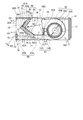
- FIG. 10 is a view of the unit main body 10 with the heat exchange chamber side bottom plate 13 ⁇ / b> A and the drain pan 70 removed, as viewed obliquely from below.
- the lower opening (opening) 40 extending over the entire bottom of the heat exchange chamber R2 is formed on the lower surface of the unit case 11 by removing the heat exchange chamber side bottom plate 13A and the drain pan 70.
- a lid body 68, a fixture 79 for fixing the drain pump, and a maintenance panel 56 are separately formed and detachably attached.
- FIG. 10 shows a state where the lid 68 is removed from the unit case 11 for convenience of explanation.
- the side plate 14A of the unit case 11 is provided with a notch 68C to which the lid 68 is attached.
- the notch 68 ⁇ / b> C is formed to open below the unit case 11 and communicate with the lower opening 40.
- the auxiliary refrigerant pipe 67 protruding outward from the side plate 14A from the indoor heat exchanger 60 is inserted into the heat exchange chamber R2 from the lower opening 40 integrally with the indoor heat exchanger 60 through the notch 68C.
- the side plate 14A is formed with semicircular inverted U-shaped grooves 66A and 66B that open downward so that the auxiliary refrigerant pipe can be inserted into the notch 68C.
- Each inverted U-shaped groove 66 ⁇ / b> A, 66 ⁇ / b> B is formed at a position corresponding to the auxiliary refrigerant pipe 67 inserted through the notch 68.
- the lid body 68 is formed with U-shaped grooves 68A and 68B that open upward at positions corresponding to the inverted U-shaped grooves 66A and 66B.
- the lid body 68 is fixed to the side plate 14 ⁇ / b> A with screws (not shown) inserted into screw holes 68 ⁇ / b> D and 68 ⁇ / b> D provided in the lower portion of the lid body 68. Accordingly, the lid body 68 closes the notch 68C of the side plate 14A.
- the lid 68 is formed with a handle 68E extending over the length L2 of the lid 68 above the screw holes 68D and 68D.
- the lid body 68 is configured to be able to be attached to and detached from the side plate 14A by pressing the handle 68E by hand.
- the auxiliary refrigerant pipe 67 is held on the side plate 14A by the cooperation of the U-shaped grooves 68A and 68B of the lid body 68 and the reverse U-shaped grooves 66A and 66B of the side plate 14A. Is done.
- a water injection opening 85 is formed in the lid 68 between the U-shaped groove 68B and the handle 68E.
- the water injection opening 85 is normally closed with a lid 86 fixed to the lid body 68 with a screw or the like.
- the lid 86 is removed from the water injection opening 85 and the heat exchange chamber R2 is passed through the water injection opening 85. It is possible to check the flow of drain water by pouring water inside.
- the lid 68 can be removed from the unit case 11 by removing the screws screwed into the screw holes 68D, 68D, and the notch 68C can be removed from the side plate 14A by removing the lid 68 from the side plate 14A. Communicate with. Thereby, the bottom surface side of the unit case 11 is opened so that the indoor heat exchange unit 80 can be pulled out from the unit case 11 and removed without removing the auxiliary refrigerant pipe 67 from the indoor heat exchange unit 80.
- the pump-down operation of the built-in type air conditioner 1 is performed.
- the pump-down operation although not shown, all the refrigerant in the indoor heat exchanger 60 is collected by the outdoor unit or the refrigerant recovery machine, the valve is closed, and the indoor heat exchanger 60 is disconnected from the refrigerant circuit.
- the heat exchange chamber side bottom plate 13A, the drain pan 70, and the lid 68 are removed from the unit case 11 through the opening of the ceiling plate 33 from which the ceiling panel 35 is removed. Thereby, a lower opening 40 for removing the indoor heat exchange unit 80 downward is formed in the lower part of the unit case 11.
- the drain pipe holder 76 and the drain drain pipe 77 penetrating the drain pipe holder 76 are put together with the drain pan 70 from the lower opening 40 from which the bottom plate 13 of the unit case 11 is removed. Can be removed.
- the screw 4 fixing the indoor heat exchange unit 80 to the unit case 11 is removed. Specifically, the screw 4 screwed into the screw hole 64B and the screw hole 69A is removed from the outside of the unit case 11, and the screw 4 screwed into the screw hole 64A and the screw hole 69B is removed from the inside of the unit case 11. Remove from.
- the indoor heat exchange unit 80 can be pulled out integrally below the unit case 11 via the lower opening 40 of the heat exchange chamber R2 and removed from the unit body 10. According to this configuration, the unit case 11 is suspended from the ceiling space 34 as shown in FIG. 1, that is, from the unit case 11 to the bottom plate as shown in FIG.
- the indoor heat exchange unit 80 can be removed from the unit case 11 by simply removing a total of six screws (three on each side) 4A and 4B screwed into the screw holes 64A and 64B. 11 can be removed. Therefore, the indoor heat exchange unit 80 can be easily removed from the conditioned room 2 side by removing the ceiling panel 35. Thereby, the work in the ceiling space 34 with a limited work space can be reduced, and the maintainability of the indoor heat exchanger 60 can be improved.
- a pump unit 75 is attached to the side plate 14A in the vicinity of the pipe presser 68.
- the pump unit 75 integrally includes a drain pump 78 and a fixture 79 to which the drain pump 78 is fixed.
- a pump fixing portion 79A to which the drain pump 78 is fixed and a lid portion 79B for closing the pump mounting opening 75A for mounting the pump unit 75 formed on the side plate 14A are integrally formed with resin.
- a drain pipe 76 is connected between the drain pump 78 and the lid 79B for draining the water sucked from the drain pan 70 by the drain pump 78 to the outside of the unit case 11.
- the pump unit 75 is integrally provided with a drain pump 78 and a fixture 79 so as to be detachable from the side plate 14A, and the lid 79B is fixed to the side plate 14A with screws or the like.
- the drain pump 78 can be easily detached from the unit case 11 integrally with the pump unit 75. Therefore, even after the piping construction in which the auxiliary refrigerant pipe 67 is connected to the indoor heat exchanger 60, the pump unit 75 can be easily removed from the unit case 11, and the drain pump 78 can be easily maintained.
- the unit main body 10 configured to accommodate the heat exchanger 60 and the blower 50 is provided, and the heat exchanger 60 has a substantially square shape in a side view. It includes an upper heat exchanging part and a lower heat exchanging part to be connected, and is provided with a blower port 50D of the blower 50 facing the apex 60A of the square shape.
- the heat exchanging part 61 is accommodated to the same width and the unit width W is almost fully accommodated, and the lower end part 61A of the upper heat exchanging part 61 is arranged on the lower heat exchanging part 62 at the apex 60A of the substantially square shape.
- the upper heat exchange unit 61 is arranged closer to the blower 50 than the upper end 62B of the lower heat exchange unit 62, and the outflow of air from the upper heat exchange unit 61
- a step 60 ⁇ / b> C is provided between the side surface 61 ⁇ / b> B and the upper end portion 62 ⁇ / b> B of the lower heat exchange unit 62.
- the drain water generated in the upper heat exchanging portion 61 and flowing under its own weight along the outflow side surface 61D is received by the step 60C formed in the connecting portion 60B between the upper heat exchanging portion 61 and the lower heat exchanging portion 62. And flows through the lower heat exchange section 62. Therefore, it is possible to prevent the drain water from splashing from the upper heat exchanging portion 61 and the connecting portion 60B of the lower heat exchanging portion 62.
- the unit main body 10 configured to accommodate the indoor heat exchanger 60 and the blower 50 is provided, and the indoor heat exchanger 60 is connected to a substantially square shape in a side view.
- the upper side heat exchanging part 61 and the lower side heat exchanging part 62 are provided, and the blower port 50D of the blower 50 is provided so as to face the apex 60A of the square shape.
- the heat exchanging part 61 is accommodated to have the same width and the unit width W is almost full, and the heat exchanging area of the lower heat exchanging part 62 is set larger than that of the upper heat exchanging part 61.
- the amount of air passing through the upper heat exchange unit 61 and the lower heat exchange unit 62 can be made substantially the same while increasing the capacity (heat exchange area) of the indoor heat exchanger 60. Therefore, the temperature difference in the heat exchange surface between the upper heat exchange unit 61 and the lower heat exchange unit 62 can be reduced, and the heat exchange efficiency of the indoor heat exchanger 60 can be made uniform.
- the heat exchange area of the upper heat exchange unit 61 is set to approximately 60% of the heat exchange area of the lower heat exchange unit 62.
- the amount of air passing through the upper heat exchange unit 61 and the lower heat exchange unit 62 can be made substantially the same. Therefore, the temperature difference in the heat exchange surface between the upper heat exchange unit 61 and the lower heat exchange unit 62 can be reduced, and the heat exchange efficiency of the indoor heat exchanger 60 can be made uniform.
- the inside of the unit body 10 is divided into a blower chamber R1 in which the blower 50 is accommodated and a heat exchange chamber R2 in which the indoor heat exchanger 60 is accommodated.
- a drain pan 70 covering the entire bottom of R2 was provided, and the lower end 62C of the lower heat exchange unit 62 was placed on the drain pan 70.
- the blower 50 can be provided substantially fully in the height direction of the blower chamber R ⁇ b> 1, the size of the unit body 10 in the height direction can be suppressed, and the upper heat exchange unit 61 and the lower heat exchange unit 62 can The drain water can be collected by a drain pan 70.
- the inside of the unit body 10 is partitioned by the partition plate 55 into a heat exchange chamber R2 that houses the heat exchanger 60 and a blower chamber R1 that houses the blower 50,
- a heat exchange chamber R2 that houses the heat exchanger 60
- a blower chamber R1 that houses the blower 50
- Resin fixing members 63A and 63B for fixing the heat exchanger 60 inside the unit body 10 are provided. Thereby, there is no need to separately provide a fixing member for fixing the heat exchanger 60 in the unit case 11, for example, by protruding from the partition plate 55. Therefore, the heat exchanger 60 can be fixed in the unit body 10 with a simple structure, and the number of parts can be reduced and the mounting workability can be improved.
- the vent hole 81 through which the U-shaped tube of the heat exchanger 60 passes is provided in the fixing member 63A on one end side of both ends of the heat exchanger 60, and the other end side is provided.
- a square-shaped groove 25 formed along the shape of the heat exchanger 60 is provided in the fixing member 63 ⁇ / b> B, and the refrigerant pipe of the heat exchanger is passed through the groove 25.
- the one end side fixing member 63A is positioned and temporarily fixed by passing the U-shaped tube of the heat exchanger 60 through the vent hole 81. Therefore, the one end side fixing member 63A can be easily fixed to the heat exchanger 60 integrally.
- the other end side fixing member 63 ⁇ / b> B includes a groove 25 formed along the shape of the heat exchanger 60, and the other end side fixing member 63 ⁇ / b> B interferes with the auxiliary refrigerant pipe 67 connected to the heat exchanger 60. Without being fixed to the heat exchanger 60 easily.
- the inside of the unit body 10 is partitioned by the partition plate 55 into a heat exchange chamber R2 that houses the heat exchanger 60 and a blower chamber R1 that houses the blower 50,
- the heat exchanger 60 is desorbed from the opening 40 on the lower surface of the unit body 10 into the heat exchange chamber R2.
- the auxiliary refrigerant pipe 67 of the heat exchanger 60 protruding outward from the side plate 14A is formed on the side plate 14A of the unit body 10 so as to be integrated with the heat exchanger 60 from the opening 40 side.
- Reverse U-shaped grooves 66A and 66B that are open downward so as to be inserted therein are provided.
- a lid body 68 having U-shaped grooves 68A and 68B is attached to the side plate 14A, and the U-shaped grooves 68A and 68B of the lid body 68 are attached.
- side plate 1 Inverted U-shaped groove 66A of the A, by 66B in cooperation with the auxiliary refrigerant pipe 67 and can be held to the side plate 14A.
- the auxiliary refrigerant pipe 67 is connected to the side plate 14A by the cooperation of the U-shaped grooves 68A and 68B of the lid body 68 and the reverse U-shaped grooves 66A and 66B of the side plate 14A. Can be held in. Further, when the heat exchanger 60 is detached, the cover body 68 is removed from the side plate 14A, so that the heat exchanger 60 and the auxiliary refrigerant pipe 67 are integrated together without removing the auxiliary refrigerant pipe 67 from the heat exchanger 60. 10 can be easily detached from the opening 40 on the lower surface. Therefore, the maintainability of the heat exchanger 60 can be improved.
- the unit main body 10 includes the drain pan 70 that receives the drain water generated by the heat exchanger 60, and the drain water accumulated in the drain pan 70 through the drain pipe 76.
- a drain pump 78 for draining outside the unit main body 10 is built in, and a pump unit 75 in which the drain pump 78 and the drain pipe 76 are integrally combined is provided in the vicinity of the lid 68 on the side surface 14 of the unit main body 10. It is arranged to be detachable. Thereby, the drain pump 78 can be easily detached from the unit body 10 integrally with the pump unit 75.
- the pump unit 75 can be easily detached from the unit body 10 even after the heat exchanger 60 and the auxiliary refrigerant pipe 67 are installed. Therefore, the drain pump 78 can be easily maintained.
- the heat exchanger 60 is provided at both ends, and is inserted into the heat exchange chamber R2 from the opening 40 side integrally with the heat exchanger 60, and the unit body 10 is blown out.
- Resin fixing members 63A and 63B that are fixed to the side panel 16 and the top plate 12 and fix the heat exchanger 60 to the inside of the unit body 10 are provided.
- the fixing members 63A, 63B are removed from the front plate 16 and the top plate 12, so that the heat exchanger 60 is integrated with the fixing members 63A, 63B in the opening on the lower surface of the unit body 10. 40 can be easily taken out. Therefore, the maintainability of the heat exchanger 60 can be improved.
- the heat exchanger 60 includes the upper heat exchanging portion 61 and the lower heat exchanging portion 62 that are connected to each other when viewed in a side view,
- the blower outlet 50D of the blower 50 was provided so as to face each other. Accordingly, the capacity (heat exchange area) of the heat exchanger 60 can be increased without changing the height of the unit case 11.
- the open side of the square shape of the indoor heat exchanger 60 is opposed to the outlet 50D of the blower 50.
- the shape of the air inlet side of the indoor heat exchanger 60 can be made to correspond to the distribution of the air volume from the blower 50, and the efficiency of heat exchange can be improved.
- the open side of the square shape of the indoor heat exchanger 60 is directed to the downstream side of the indoor heat exchanger 60.
- the blower 50 is a sirocco fan that is a centrifugal blower, a large static pressure can be obtained, and the indoor heat exchanger 60 and the ceiling plate are provided downstream of the blower 50. Even with a built-in type air conditioner having a relatively long blowing duct 54 extending to 33, a large air flow rate can be obtained.
Landscapes
- Engineering & Computer Science (AREA)
- Mechanical Engineering (AREA)
- General Engineering & Computer Science (AREA)
- Chemical & Material Sciences (AREA)
- Combustion & Propulsion (AREA)
- Physics & Mathematics (AREA)
- Thermal Sciences (AREA)
- Devices For Blowing Cold Air, Devices For Blowing Warm Air, And Means For Preventing Water Condensation In Air Conditioning Units (AREA)
- Air Filters, Heat-Exchange Apparatuses, And Housings Of Air-Conditioning Units (AREA)
Abstract
L'invention fournit un dispositif de conditionnement d'air encastrable présentant des caractéristiques de rendement et d'entretien d'échangeur de chaleur interne améliorées. Un échangeur de chaleur (60) contient une unité échange de chaleur côté supérieur et une unité échange de chaleur côté inférieur raccordées de sorte à former un V selon une vue latérale, et est disposé de sorte que l'extrémité inférieure de l'unité échange de chaleur côté supérieur se superpose au haut de l'unité échange de chaleur côté inférieur à la pointe du V. En outre, la surface d'échange de chaleur de l'unité échange de chaleur côté inférieur, est établie de sorte à être plus grande que celle de l'unité échange de chaleur côté supérieur. Sont agencées des rainures (66A, 66B) en forme de U inversé qui s'ouvrent vers le bas de manière à permettre l'insertion à l'intérieur d'une chambre d'échange de chaleur d'un conduit auxiliaire de frigorigène (67) de l'échangeur de chaleur (60) d'un seul tenant avec ce dernier. Enfin, des éléments de fixation (63A, 63B) en résine qui sont destinés à fixer l'échangeur de chaleur (60) côté interne d'un corps principal d'unité (10), par fixation à une plaque avant (16) et à une plaque supérieure (12) du corps principal d'unité (10), sont agencés aux deux extrémités de l'échangeur de chaleur (60).
Priority Applications (4)
| Application Number | Priority Date | Filing Date | Title |
|---|---|---|---|
| ES12803151T ES2734354T3 (es) | 2011-06-20 | 2012-06-20 | Dispositivo de acondicionamiento de aire del tipo empotrado |
| JP2013521598A JP5995107B2 (ja) | 2011-06-20 | 2012-06-20 | ビルトイン型空気調和装置 |
| EP12803151.5A EP2722609B1 (fr) | 2011-06-20 | 2012-06-20 | Dispositif de conditionnement d'air encastrable |
| CN201280030248.1A CN103608629B (zh) | 2011-06-20 | 2012-06-20 | 嵌入式空调装置 |
Applications Claiming Priority (8)
| Application Number | Priority Date | Filing Date | Title |
|---|---|---|---|
| JP2011136241 | 2011-06-20 | ||
| JP2011-136240 | 2011-06-20 | ||
| JP2011-136241 | 2011-06-20 | ||
| JP2011136240 | 2011-06-20 | ||
| JP2011144143 | 2011-06-29 | ||
| JP2011-144143 | 2011-06-29 | ||
| JP2011-144141 | 2011-06-29 | ||
| JP2011144141 | 2011-06-29 |
Publications (1)
| Publication Number | Publication Date |
|---|---|
| WO2012176805A1 true WO2012176805A1 (fr) | 2012-12-27 |
Family
ID=47422637
Family Applications (1)
| Application Number | Title | Priority Date | Filing Date |
|---|---|---|---|
| PCT/JP2012/065747 Ceased WO2012176805A1 (fr) | 2011-06-20 | 2012-06-20 | Dispositif de conditionnement d'air encastrable |
Country Status (5)
| Country | Link |
|---|---|
| EP (1) | EP2722609B1 (fr) |
| JP (1) | JP5995107B2 (fr) |
| CN (1) | CN103608629B (fr) |
| ES (1) | ES2734354T3 (fr) |
| WO (1) | WO2012176805A1 (fr) |
Cited By (9)
| Publication number | Priority date | Publication date | Assignee | Title |
|---|---|---|---|---|
| JP2015132401A (ja) * | 2014-01-10 | 2015-07-23 | 三菱電機株式会社 | 室外ユニット |
| JP2015175558A (ja) * | 2014-03-17 | 2015-10-05 | 株式会社富士通ゼネラル | ダクト型空気調和機 |
| CN105705870A (zh) * | 2013-12-26 | 2016-06-22 | 东芝开利株式会社 | 空调和热交换器 |
| JP2016223638A (ja) * | 2015-05-27 | 2016-12-28 | 株式会社富士通ゼネラル | ダクト型空気調和機 |
| JP2016223637A (ja) * | 2015-05-27 | 2016-12-28 | 株式会社富士通ゼネラル | ダクト型空気調和機 |
| WO2016208567A1 (fr) * | 2015-06-25 | 2016-12-29 | 東芝キヤリア株式会社 | Échangeur de chaleur et climatiseur du type à installation au plafond |
| WO2018235134A1 (fr) * | 2017-06-19 | 2018-12-27 | 三菱電機株式会社 | Unité, climatiseur et procédé de fabrication d'échangeur de chaleur |
| JP2019015494A (ja) * | 2017-07-07 | 2019-01-31 | 三星電子株式会社Samsung Electronics Co.,Ltd. | 熱交換器、室内機、及び、空気調和装置 |
| WO2024127458A1 (fr) * | 2022-12-12 | 2024-06-20 | 三菱電機株式会社 | Dispositif de climatisation et son procédé de construction |
Families Citing this family (11)
| Publication number | Priority date | Publication date | Assignee | Title |
|---|---|---|---|---|
| KR102337163B1 (ko) * | 2014-11-12 | 2021-12-09 | 삼성전자주식회사 | 덕트형 공기조화장치 및 그 조립 및 분해방법 |
| CN105003969A (zh) * | 2015-07-24 | 2015-10-28 | 广东美的暖通设备有限公司 | 一种排水泵位于中隔板且可拆卸的风管机以及空调 |
| CN105588196A (zh) * | 2015-12-03 | 2016-05-18 | 青岛海信日立空调系统有限公司 | 一种空调室内机 |
| JP2017129309A (ja) * | 2016-01-20 | 2017-07-27 | 三菱重工業株式会社 | 空気調和機 |
| CN106403040A (zh) * | 2016-11-03 | 2017-02-15 | 珠海格力电器股份有限公司 | 空调出风结构和空调器 |
| WO2019009681A1 (fr) | 2017-07-07 | 2019-01-10 | 삼성전자주식회사 | Échangeur de chaleur et appareil intérieur doté dudit échangeur |
| EP3726150B1 (fr) * | 2017-12-13 | 2023-09-13 | Mitsubishi Electric Corporation | Unité d'échange de chaleur et dispositif de climatisation dans lequel celle-ci est montée |
| US10830490B2 (en) | 2018-08-01 | 2020-11-10 | Johnson Controls Technology Company | Liquid drainage systems and methods |
| CN115432021A (zh) * | 2022-09-14 | 2022-12-06 | 株洲创春科技实业有限责任公司 | 一种轨道交通用司机室均风结构 |
| CN116045416A (zh) * | 2022-12-15 | 2023-05-02 | 珠海格力节能环保制冷技术研究中心有限公司 | 壳体组件及具有其的风管机 |
| WO2024255137A1 (fr) * | 2023-06-12 | 2024-12-19 | 青岛海信日立空调系统有限公司 | Climatiseur |
Citations (14)
| Publication number | Priority date | Publication date | Assignee | Title |
|---|---|---|---|---|
| JPS5419357U (fr) * | 1977-07-11 | 1979-02-07 | ||
| JPH0188317U (fr) * | 1987-11-30 | 1989-06-12 | ||
| JPH0432628A (ja) * | 1990-05-28 | 1992-02-04 | Mitsubishi Electric Corp | 埋込形空気調和機 |
| JPH06307663A (ja) * | 1993-04-22 | 1994-11-01 | Daikin Ind Ltd | 天井埋込型空気調和機 |
| JPH07198156A (ja) * | 1993-11-29 | 1995-08-01 | Sanyo Electric Co Ltd | 空気調和装置 |
| JPH0960911A (ja) * | 1995-08-21 | 1997-03-04 | Fujitsu General Ltd | 空気調和機 |
| JPH10246506A (ja) * | 1997-03-03 | 1998-09-14 | Hitachi Ltd | 空気調和機用室内ユニット |
| JP2000088269A (ja) * | 1998-09-10 | 2000-03-31 | Daikin Ind Ltd | 空気調和機 |
| JP2001174047A (ja) * | 1999-12-17 | 2001-06-29 | Matsushita Electric Ind Co Ltd | 空気調和機の室内機 |
| JP2002162064A (ja) | 2000-11-20 | 2002-06-07 | Daikin Ind Ltd | 空気調和機 |
| JP2003042478A (ja) * | 2001-07-27 | 2003-02-13 | Daikin Ind Ltd | 熱交換器固定板およびそれを用いた熱交換器固定方法および空気調和機 |
| JP2007147144A (ja) * | 2005-11-25 | 2007-06-14 | Daikin Ind Ltd | 空気調和装置 |
| JP2008082646A (ja) * | 2006-09-28 | 2008-04-10 | Fujitsu General Ltd | 熱交換器固定板及びこれを備えた空気調和機 |
| JP2008261541A (ja) * | 2007-04-11 | 2008-10-30 | Kimura Kohki Co Ltd | 天井設置形ファンコイルユニット |
Family Cites Families (5)
| Publication number | Priority date | Publication date | Assignee | Title |
|---|---|---|---|---|
| US4000779A (en) * | 1975-11-28 | 1977-01-04 | General Electric Company | Blowoff baffle |
| JP4110375B2 (ja) * | 2002-06-27 | 2008-07-02 | 株式会社富士通ゼネラル | 空気調和機 |
| JP4586973B2 (ja) * | 2005-01-17 | 2010-11-24 | 株式会社富士通ゼネラル | 空気調和機 |
| CN101625143B (zh) * | 2008-07-07 | 2011-11-23 | 松下电器产业株式会社 | 多功能换气扇 |
| US9982898B2 (en) * | 2009-02-05 | 2018-05-29 | Mitsubishi Electric Corporation | Indoor unit of air conditioner and air conditioner including a heat exchanger on a downstream side of a blower |
-
2012
- 2012-06-20 JP JP2013521598A patent/JP5995107B2/ja active Active
- 2012-06-20 EP EP12803151.5A patent/EP2722609B1/fr active Active
- 2012-06-20 WO PCT/JP2012/065747 patent/WO2012176805A1/fr not_active Ceased
- 2012-06-20 CN CN201280030248.1A patent/CN103608629B/zh active Active
- 2012-06-20 ES ES12803151T patent/ES2734354T3/es active Active
Patent Citations (14)
| Publication number | Priority date | Publication date | Assignee | Title |
|---|---|---|---|---|
| JPS5419357U (fr) * | 1977-07-11 | 1979-02-07 | ||
| JPH0188317U (fr) * | 1987-11-30 | 1989-06-12 | ||
| JPH0432628A (ja) * | 1990-05-28 | 1992-02-04 | Mitsubishi Electric Corp | 埋込形空気調和機 |
| JPH06307663A (ja) * | 1993-04-22 | 1994-11-01 | Daikin Ind Ltd | 天井埋込型空気調和機 |
| JPH07198156A (ja) * | 1993-11-29 | 1995-08-01 | Sanyo Electric Co Ltd | 空気調和装置 |
| JPH0960911A (ja) * | 1995-08-21 | 1997-03-04 | Fujitsu General Ltd | 空気調和機 |
| JPH10246506A (ja) * | 1997-03-03 | 1998-09-14 | Hitachi Ltd | 空気調和機用室内ユニット |
| JP2000088269A (ja) * | 1998-09-10 | 2000-03-31 | Daikin Ind Ltd | 空気調和機 |
| JP2001174047A (ja) * | 1999-12-17 | 2001-06-29 | Matsushita Electric Ind Co Ltd | 空気調和機の室内機 |
| JP2002162064A (ja) | 2000-11-20 | 2002-06-07 | Daikin Ind Ltd | 空気調和機 |
| JP2003042478A (ja) * | 2001-07-27 | 2003-02-13 | Daikin Ind Ltd | 熱交換器固定板およびそれを用いた熱交換器固定方法および空気調和機 |
| JP2007147144A (ja) * | 2005-11-25 | 2007-06-14 | Daikin Ind Ltd | 空気調和装置 |
| JP2008082646A (ja) * | 2006-09-28 | 2008-04-10 | Fujitsu General Ltd | 熱交換器固定板及びこれを備えた空気調和機 |
| JP2008261541A (ja) * | 2007-04-11 | 2008-10-30 | Kimura Kohki Co Ltd | 天井設置形ファンコイルユニット |
Non-Patent Citations (1)
| Title |
|---|
| See also references of EP2722609A4 |
Cited By (14)
| Publication number | Priority date | Publication date | Assignee | Title |
|---|---|---|---|---|
| CN105705870B (zh) * | 2013-12-26 | 2018-10-12 | 东芝开利株式会社 | 空调和热交换器 |
| CN105705870A (zh) * | 2013-12-26 | 2016-06-22 | 东芝开利株式会社 | 空调和热交换器 |
| JP2015132401A (ja) * | 2014-01-10 | 2015-07-23 | 三菱電機株式会社 | 室外ユニット |
| JP2015175558A (ja) * | 2014-03-17 | 2015-10-05 | 株式会社富士通ゼネラル | ダクト型空気調和機 |
| JP2016223638A (ja) * | 2015-05-27 | 2016-12-28 | 株式会社富士通ゼネラル | ダクト型空気調和機 |
| JP2016223637A (ja) * | 2015-05-27 | 2016-12-28 | 株式会社富士通ゼネラル | ダクト型空気調和機 |
| WO2016208567A1 (fr) * | 2015-06-25 | 2016-12-29 | 東芝キヤリア株式会社 | Échangeur de chaleur et climatiseur du type à installation au plafond |
| AU2016281336B2 (en) * | 2015-06-25 | 2019-01-31 | Toshiba Carrier Corporation | Ceiling installation type air conditioner and heat exchanger |
| WO2018235134A1 (fr) * | 2017-06-19 | 2018-12-27 | 三菱電機株式会社 | Unité, climatiseur et procédé de fabrication d'échangeur de chaleur |
| JPWO2018235134A1 (ja) * | 2017-06-19 | 2019-12-26 | 三菱電機株式会社 | ユニット、空気調和機、及び、熱交換器の製造方法 |
| JP2019015494A (ja) * | 2017-07-07 | 2019-01-31 | 三星電子株式会社Samsung Electronics Co.,Ltd. | 熱交換器、室内機、及び、空気調和装置 |
| WO2024127458A1 (fr) * | 2022-12-12 | 2024-06-20 | 三菱電機株式会社 | Dispositif de climatisation et son procédé de construction |
| JPWO2024127458A1 (fr) * | 2022-12-12 | 2024-06-20 | ||
| JP7829733B2 (ja) | 2022-12-12 | 2026-03-13 | 三菱電機株式会社 | 空気調和装置及びその施工方法 |
Also Published As
| Publication number | Publication date |
|---|---|
| CN103608629B (zh) | 2016-05-25 |
| EP2722609A4 (fr) | 2015-08-12 |
| EP2722609B1 (fr) | 2019-05-01 |
| CN103608629A (zh) | 2014-02-26 |
| ES2734354T3 (es) | 2019-12-05 |
| JP5995107B2 (ja) | 2016-09-21 |
| EP2722609A1 (fr) | 2014-04-23 |
| JPWO2012176805A1 (ja) | 2015-02-23 |
Similar Documents
| Publication | Publication Date | Title |
|---|---|---|
| JP5995107B2 (ja) | ビルトイン型空気調和装置 | |
| JP5587060B2 (ja) | ビルトイン型空気調和装置 | |
| JP6488886B2 (ja) | ダクト型空気調和機 | |
| JPWO2013046899A1 (ja) | 空気調和装置 | |
| JP5884069B2 (ja) | ビルトイン型空気調和装置 | |
| JP5123018B2 (ja) | 空調装置 | |
| JP4183053B2 (ja) | 空気調和機の室外ユニット | |
| JP4585377B2 (ja) | 空気調和装置 | |
| JPH1030827A (ja) | 空気調和機 | |
| JP4373167B2 (ja) | 空気調和装置の室外ユニット | |
| US11898762B2 (en) | Ceiling-embedded air conditioner | |
| JP2011208847A (ja) | ダクト型空気調和機 | |
| JP4081681B2 (ja) | 室内機本体及び空気調和機 | |
| JP2013213595A (ja) | ビルトイン型空気調和機 | |
| JP2007003044A (ja) | 空気調和機 | |
| JP2004085000A (ja) | 空気調和機の室内機 | |
| JP2011163564A (ja) | 空気調和機の室内ユニット | |
| JP2006097937A (ja) | 天井埋込み形空気調和機 | |
| JP5001630B2 (ja) | ドレンパンおよびこれを用いた空調ユニットならびに空気調和装置 | |
| JP5720598B2 (ja) | 空気調和装置の室内機 | |
| JP2006097995A (ja) | 空気調和装置 | |
| JP4915100B2 (ja) | 空気調和機の室内機 | |
| JP2010117056A (ja) | 送風装置 | |
| JP2019178833A (ja) | 天井埋込型空気調和機 | |
| JP2005315436A (ja) | 天井埋込型空気調和機 |
Legal Events
| Date | Code | Title | Description |
|---|---|---|---|
| 121 | Ep: the epo has been informed by wipo that ep was designated in this application |
Ref document number: 12803151 Country of ref document: EP Kind code of ref document: A1 |
|
| DPE1 | Request for preliminary examination filed after expiration of 19th month from priority date (pct application filed from 20040101) | ||
| ENP | Entry into the national phase |
Ref document number: 2013521598 Country of ref document: JP Kind code of ref document: A |
|
| NENP | Non-entry into the national phase |
Ref country code: DE |
|
| WWE | Wipo information: entry into national phase |
Ref document number: 2012803151 Country of ref document: EP |