WO2012176843A1 - 複合接点の製造方法 - Google Patents
複合接点の製造方法 Download PDFInfo
- Publication number
- WO2012176843A1 WO2012176843A1 PCT/JP2012/065870 JP2012065870W WO2012176843A1 WO 2012176843 A1 WO2012176843 A1 WO 2012176843A1 JP 2012065870 W JP2012065870 W JP 2012065870W WO 2012176843 A1 WO2012176843 A1 WO 2012176843A1
- Authority
- WO
- WIPO (PCT)
- Prior art keywords
- copper alloy
- hole
- silver alloy
- diameter
- section
- Prior art date
- Legal status (The legal status is an assumption and is not a legal conclusion. Google has not performed a legal analysis and makes no representation as to the accuracy of the status listed.)
- Ceased
Links
Images







Classifications
-
- H—ELECTRICITY
- H01—ELECTRIC ELEMENTS
- H01R—ELECTRICALLY-CONDUCTIVE CONNECTIONS; STRUCTURAL ASSOCIATIONS OF A PLURALITY OF MUTUALLY-INSULATED ELECTRICAL CONNECTING ELEMENTS; COUPLING DEVICES; CURRENT COLLECTORS
- H01R43/00—Apparatus or processes specially adapted for manufacturing, assembling, maintaining, or repairing of line connectors or current collectors or for joining electric conductors
- H01R43/16—Apparatus or processes specially adapted for manufacturing, assembling, maintaining, or repairing of line connectors or current collectors or for joining electric conductors for manufacturing contact members, e.g. by punching and by bending
-
- H—ELECTRICITY
- H01—ELECTRIC ELEMENTS
- H01H—ELECTRIC SWITCHES; RELAYS; SELECTORS; EMERGENCY PROTECTIVE DEVICES
- H01H1/00—Contacts
- H01H1/02—Contacts characterised by the material thereof
- H01H1/021—Composite material
- H01H1/023—Composite material having a noble metal as the basic material
-
- B—PERFORMING OPERATIONS; TRANSPORTING
- B21—MECHANICAL METAL-WORKING WITHOUT ESSENTIALLY REMOVING MATERIAL; PUNCHING METAL
- B21J—FORGING; HAMMERING; PRESSING METAL; RIVETING; FORGE FURNACES
- B21J15/00—Riveting
- B21J15/02—Riveting procedures
-
- B—PERFORMING OPERATIONS; TRANSPORTING
- B21—MECHANICAL METAL-WORKING WITHOUT ESSENTIALLY REMOVING MATERIAL; PUNCHING METAL
- B21K—MAKING FORGED OR PRESSED METAL PRODUCTS, e.g. HORSE-SHOES, RIVETS, BOLTS OR WHEELS
- B21K1/00—Making machine elements
- B21K1/58—Making machine elements rivets
- B21K1/62—Making machine elements rivets special rivets, e.g. with electrical contacts
-
- B—PERFORMING OPERATIONS; TRANSPORTING
- B23—MACHINE TOOLS; METAL-WORKING NOT OTHERWISE PROVIDED FOR
- B23K—SOLDERING OR UNSOLDERING; WELDING; CLADDING OR PLATING BY SOLDERING OR WELDING; CUTTING BY APPLYING HEAT LOCALLY, e.g. FLAME CUTTING; WORKING BY LASER BEAM
- B23K11/00—Resistance welding; Severing by resistance heating
- B23K11/02—Pressure butt welding
-
- B—PERFORMING OPERATIONS; TRANSPORTING
- B23—MACHINE TOOLS; METAL-WORKING NOT OTHERWISE PROVIDED FOR
- B23K—SOLDERING OR UNSOLDERING; WELDING; CLADDING OR PLATING BY SOLDERING OR WELDING; CUTTING BY APPLYING HEAT LOCALLY, e.g. FLAME CUTTING; WORKING BY LASER BEAM
- B23K20/00—Non-electric welding by applying impact or other pressure, with or without the application of heat, e.g. cladding or plating
- B23K20/02—Non-electric welding by applying impact or other pressure, with or without the application of heat, e.g. cladding or plating by means of a press ; Diffusion bonding
- B23K20/028—Butt welding
-
- H—ELECTRICITY
- H01—ELECTRIC ELEMENTS
- H01H—ELECTRIC SWITCHES; RELAYS; SELECTORS; EMERGENCY PROTECTIVE DEVICES
- H01H11/00—Apparatus or processes specially adapted for the manufacture of electric switches
- H01H11/04—Apparatus or processes specially adapted for the manufacture of electric switches of switch contacts
- H01H11/041—Apparatus or processes specially adapted for the manufacture of electric switches of switch contacts by bonding of a contact marking face to a contact body portion
- H01H11/042—Apparatus or processes specially adapted for the manufacture of electric switches of switch contacts by bonding of a contact marking face to a contact body portion by mechanical deformation
-
- B—PERFORMING OPERATIONS; TRANSPORTING
- B23—MACHINE TOOLS; METAL-WORKING NOT OTHERWISE PROVIDED FOR
- B23K—SOLDERING OR UNSOLDERING; WELDING; CLADDING OR PLATING BY SOLDERING OR WELDING; CUTTING BY APPLYING HEAT LOCALLY, e.g. FLAME CUTTING; WORKING BY LASER BEAM
- B23K2101/00—Articles made by soldering, welding or cutting
- B23K2101/36—Electric or electronic devices
- B23K2101/38—Conductors
-
- H—ELECTRICITY
- H01—ELECTRIC ELEMENTS
- H01H—ELECTRIC SWITCHES; RELAYS; SELECTORS; EMERGENCY PROTECTIVE DEVICES
- H01H1/00—Contacts
- H01H1/02—Contacts characterised by the material thereof
- H01H1/021—Composite material
- H01H1/023—Composite material having a noble metal as the basic material
- H01H1/0237—Composite material having a noble metal as the basic material and containing oxides
-
- Y—GENERAL TAGGING OF NEW TECHNOLOGICAL DEVELOPMENTS; GENERAL TAGGING OF CROSS-SECTIONAL TECHNOLOGIES SPANNING OVER SEVERAL SECTIONS OF THE IPC; TECHNICAL SUBJECTS COVERED BY FORMER USPC CROSS-REFERENCE ART COLLECTIONS [XRACs] AND DIGESTS
- Y10—TECHNICAL SUBJECTS COVERED BY FORMER USPC
- Y10T—TECHNICAL SUBJECTS COVERED BY FORMER US CLASSIFICATION
- Y10T29/00—Metal working
- Y10T29/49—Method of mechanical manufacture
- Y10T29/49002—Electrical device making
- Y10T29/49117—Conductor or circuit manufacturing
- Y10T29/49204—Contact or terminal manufacturing
Definitions
- the present invention relates to a method for producing a composite contact having excellent durability and exhibiting stable contact performance over a long period with a small amount of silver alloy.
- the present application claims priority based on Japanese Patent Application No. 2011-141053 filed in Japan on June 24, 2011 and Patent Application 20121200104066.9 filed in the People's Republic of China on January 13, 2012. Is incorporated herein by reference.
- silver alloy material is used only for the contact part to save silver, and other parts are made of copper-based material.
- Alternative composite contacts are widely used. This type of composite contact has a rivet shape in which a large-diameter collar is formed on one end of a small-diameter base, and a contact portion made of a silver alloy that constitutes the upper surface of the collar, and a contact And a foot portion made of a copper alloy integrally formed with the base portion.
- Such composite contacts are formed by matching and forging the copper alloy strands that form the feet and the silver alloy strands that form the contact portions, but in order to avoid eccentricity during joining, the joining process Is generally performed in two or more times.
- a copper alloy wire and a silver alloy wire are concentrically butted together, and a die having an opening that is enlarged in a trumpet shape is pressed outwardly while pressing the butted portions of both strands.
- a technique for performing secondary (finishing) forming into a rivet shape by upsetting forging after pre-forming so as to bulge to the surface is disclosed.
- Patent Document 2 In the case of joining by such a butt, the bonding strength of the silver alloy and the copper alloy tends to be lowered at the outer peripheral portion after molding, and there is a concern that it may be peeled off due to thermal stress generated during use as a contact, leading to a decrease in durability. Is done. Therefore, in order to avoid this, there has also been proposed a method in which after the outer diameter of the final shape is expanded and molded, the portion with weak joint strength at the outer periphery is removed and only the central portion with excellent joint strength is used. (Patent Document 2).
- the present invention has been made in view of such circumstances, and improves the bonding strength of the interface with a small amount of silver alloy, eliminates waste during manufacturing, and is excellent in durability that exhibits stable contact performance over a long period of time.
- Another object of the present invention is to provide a manufacturing method capable of obtaining a composite contact.
- Patent Document 1 the forging method described in Patent Document 1 is based on the premise that the silver alloy and the copper alloy have the same diameter.
- the silver alloy is made in a small amount and the wire diameter of the silver alloy is smaller than the wire diameter of the copper alloy, It is difficult to obtain a flat joint interface.
- the present invention has the following solutions.
- a large-diameter collar is formed at one end of a small-diameter base, and a contact part made of a silver alloy constituting the upper surface of the collar, and the contact part
- a method of manufacturing a composite contact having a foot portion made of a copper alloy in which a large diameter portion constituting a lower surface portion of the flange portion and a small diameter base portion are integrally formed in a state of being joined to the back surface of the flange portion By forging the alloy wire and a silver alloy wire having a smaller outer diameter than the copper alloy wire in a state where they are abutted in the hole of the molding die, the diameter of the copper alloy wire is increased.
- a primary molding step of forming a primary molded body, and the silver alloy part, the silver alloy part and the front of the primary molded body Wherein the forged one end portion including the joining portion and the copper alloy of the copper alloy portion and a secondary molding step of molding the flange portion.
- the diameter of the copper alloy wire by forging is limited by the inner peripheral surface of the hole of the molding die, and the silver alloy wire having a small outer diameter is joined to the state of expanding to the inner diameter of the hole.
- the joint is deformed to further expand its diameter. Therefore, in the secondary forming process, the joint portion between the copper alloy portion and the silver alloy portion expands while forming a new surface, and pressure always acts on the new surface, so that the outer periphery is strong. Can be obtained. For this reason, it is not necessary to cut off the outer peripheral portion as described in Patent Document 2, and no waste occurs.
- the hole is formed by an opening of a die of the molding die, and the primary forming step leaves a space portion in the opening end of the hole in the hole.
- the copper alloy strand is accommodated in an inserted state, and the silver alloy strand and the copper alloy strand are forged in the space.
- the molding die is provided with a sleeve having the same inner diameter as the opening so as to extend the opening of the die, and the hole is formed by the sleeve, and the opening is formed in the opening of the die.
- the silver alloy wire can be forged with the diameter of the copper alloy wire being restricted and expanded to the inner diameter of the die hole or sleeve hole, and the subsequent secondary forming step.
- the amount of deformation in can be increased.
- the state in which the diameter expansion of the copper alloy wire is limited by the inner peripheral surface of the hole of the molding die is the amount of the gap generated between the outer peripheral surface of the copper alloy wire and the peripheral surface of the hole of the molding die. Allow the alloy wire to expand.
- the hole may be formed to have an inner diameter substantially the same as the outer diameter of the copper alloy wire, and the hole is larger than the outer diameter of the copper alloy wire. It may be formed to have an inner diameter where a ring-shaped space is formed between the outer peripheral surface of the strands. If the inside diameter of the die opening of the molding die is larger than the outside diameter of the copper alloy wire, the copper alloy wire is placed inside the opening to place the copper alloy wire in the center of the die opening of the molding die. You may form the recessed part of the shape which made the peripheral part the taper surface in the front-end
- the deformation of the copper alloy wire is limited in the primary forming step, and the silver alloy wire having a smaller outer diameter is deformed to the inner diameter of the hole of the molding die. And since the diameter of the joint is expanded in a state where pressure is always applied in the secondary molding step, a strong joint can be obtained up to the outer peripheral edge. Therefore, it is possible to improve the joint strength at the interface with a small amount of silver alloy, eliminate waste during manufacture, and obtain a composite contact excellent in durability that exhibits stable contact performance over a long period of time.
- FIG. 6 is a longitudinal sectional view showing a state in which a punch and a punch sleeve are retracted from the state shown in FIG. 5 and a part including a joint part of a silver alloy part and a copper alloy part of a primary molded body is protruded from a hole of a die. It is a longitudinal cross-sectional view which shows the state which opposed the punch for secondary shaping
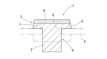
- the composite contact 1 of this embodiment has a rivet shape as a whole in which a large-diameter collar 3 is formed at one end of a small-diameter base 2, and an upper surface portion of the collar 3. And a contact portion 4 made of a silver alloy constituting the base portion 2, and a copper alloy formed integrally with the base portion 2, which is located on the back surface of the contact portion 4 and constitutes the lower surface portion of the flange portion 3 joined thereto. And a foot 6.
- Reference numeral 7 denotes a bonding interface between the contact portion 4 and the foot portion 6.
- the contact portion 4 and the foot portion 6 are pressure-contacted by abutting a wire material made of a silver alloy and a wire material made of a copper alloy and cold-working the header.
- a heat treatment at 300 ° C. to 400 ° C. is performed after the pressure welding.
- the base 2 of the foot 6 is inserted into the hole 9 of the base plate 8 made of copper or copper alloy or the like.
- the silver alloy constituting the contact portion 4 may be a pure Ag alloy, an Ag—Cu alloy, an Ag—CuO alloy, an Ag—Ni alloy, an Ag—ZnO alloy, an Ag— A Pd alloy, an Ag—SnO 2 alloy, an Ag—CdO alloy, an Ag—SnO 2 —In 2 O 3 alloy, or the like can be used.
- the copper alloy constituting the foot portion 6 includes a Cu—Co—P—Ni—Sn—Zn alloy, a Cu—Zr alloy, and a Cu—Zr alloy.
- Precipitation strengthened copper alloys such as —Cr alloy, Cu—Cr alloy, Cu—Fe—P alloy, and solid solution strengthened copper alloys such as Cu—Mg alloy can be used.
- Each of these copper alloys has a Vickers hardness of 80 HV to 185 HV and a hardness of 80% to 160% with respect to the silver alloy constituting the contact portion 4 (for example, the Vickers hardness is 90 HV to 130 HV). Yes.
- the Vickers hardness of the copper alloy and the silver alloy according to the contact shape and the desired shape of the interface of the bonding interface 7, the copper alloy is largely deformed at the time of bonding, and the outer periphery of the copper alloy is silver.
- the alloy layer can be sufficiently expanded, and the joint strength between the two can be improved.
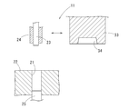
- FIG. 2 shows a molding die used in manufacturing.
- this molding die 11 the primary molding step for joining the copper alloy strand 12 and the silver alloy strand 13 cut to a predetermined length and the secondary molding step for molding the joined portion of the primary molded body 15 are the same.
- the punch 23 and the punch sleeve 24 used in the primary molding and the punch 33 used in the secondary molding are continuously molded while being replaced.
- the copper alloy wire 12 has an outer diameter that is substantially the same as or smaller than that of the foot portion 6 of the composite contact 1, but the silver alloy wire 13 is used in an amount of use.
- the length is too short, making it difficult to handle shearing or clamping of the material. It is done.
- the copper alloy wire 12 and the silver alloy wire 13 are cut to a predetermined length according to the volume used in the composite contact 1, and then are held and transferred by a clamp or the like.
- 3 to 8 illustrate a method of manufacturing a composite contact using this molding die 11 in the order of steps. Hereinafter, the manufacturing method will be described in the order of steps while also explaining the molding die 11 with reference to FIGS.
- an ejector pin 25 having a function of sliding and holding at a predetermined position.
- the ejector pin 25 has a function of holding a predetermined position in the primary molding and the secondary molding, forming a part of the forging die, and discharging the molded composite contact 1 from the hole 21 after the secondary molding is completed. It has.
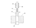
- the hole 21 of the die 22 is slightly larger than the outer diameter of the copper alloy strand 12 to such an extent that the copper alloy strand 12 can be inserted, but is formed with substantially the same inner diameter, and the punch 23 is formed of the silver alloy strand.
- the outer diameter of the wire 13 is substantially the same as the outer diameter (see FIG. 3).
- the punch sleeve 24 is formed to have an outer diameter larger than the inner diameter of the hole 21 of the die 22, and when the punch 23 faces the hole 21 of the die 22, the punch sleeve 24 surrounds the punch 23 on the surface of the die 22.
- the opening of the hole 21 can be closed (see FIG. 4).
- the ejector pin 25 has a position where its tip is retracted from the opening end of the hole 21 to a depth equal to or greater than the length of the copper alloy wire 12 (position shown in FIG. 4) and a position disposed at the opening end of the hole 21. Slide between.
- a space portion 26 is formed between the tip of the copper alloy wire 12 accommodated in the hole 21 and the opening end of the hole 21.
- the silver alloy strand 13 is forged by the punch 23 in this space portion 26 and joined to the copper alloy strand 12 at the joining interface 19.
- the primary forming process will be described in detail.
- the copper alloy wire 12 and the silver alloy wire 13 are abutted on the same axis directly above the hole 21 of the die 22, and the punch 23 slides downward in the punch sleeve 24. By doing so, it is inserted into the hole 21 of the die 22 in the butted state, and is fixed so as to be sandwiched between the ejector pin 25 held at a predetermined position inside.
- the copper alloy strand 12 is entirely accommodated in the hole 21 of the die 22, and a part of the silver alloy strand 13 is inserted in the hole 21. Therefore, the above-described space portion 26 is formed between the butted surface of the copper alloy wire 12 and the opening end of the hole 21.
- the punch sleeve 24 is brought into contact with the upper surface of the die 22 to close the opening of the hole 21 around the punch 23.
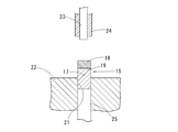
- the copper alloy wire 12 and the silver alloy wire 13 in a butted state are forged by the punch 23, the copper alloy wire 12 and the silver alloy wire 13 are formed between the ejector pin 25 and the punch 23. It is crushed in the axial direction and expanded outward in the radial direction, and is surrounded by the copper alloy wire 12, the inner peripheral surface of the hole 21 of the die 22, and the front end surface of the punch sleeve 24 as shown in FIG. 5. To fill the space. At this time, the outer diameter of the copper alloy wire 12 and the inner diameter of the hole 21 of the die 22 are only a slight difference to the extent that the copper alloy wire 12 can be inserted.
- the diameter of 12 is substantially constrained by the inner peripheral surface of the hole 21, and only the silver alloy wire 13 is deformed in the space 26 and is expanded until it becomes the same as the inner diameter of the hole 21 of the die 22. Bonded to the tip surface of the alloy wire 12.
- a portion that is the copper alloy strand 12 is referred to as a copper alloy portion 17, and a portion that is the silver alloy strand 13 is referred to as a silver alloy portion 18.
- Reference numeral 19 indicates a joint portion between the copper alloy portion 17 and the silver alloy portion 18. Since the silver alloy strand 13 is forged while the diameter of the copper alloy strand 12 is constrained, the joining is performed.
- the interface 19 is formed substantially flat at right angles to the axial direction.
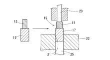
- the ejector pin 25 slides inside the hole 21 of the die 22, and the punch 23 and the punch sleeve 24 are retracted synchronously and fixed at a position prepared for the secondary forming. .
- the base end portion of the silver alloy portion 18 of the primary molded body 15 is left inserted in the hole 21 of the die 22, and the copper alloy portion 17 and a part of the silver alloy portion 18 are exposed to the outside of the die 22. That is, the bonding interface 19 is exposed to the outside of the die 22.
- a punch 33 is disposed immediately above the hole 21 of the die 22, and the copper protruding from the hole 21
- One end portion (the end portion on the silver alloy portion side) including the bonding interface 19 between the alloy portion 17 and the silver alloy portion 18 is forged.
- the punch 33 is formed with a concave portion 34 having an inner diameter larger than the inner diameter of the hole 21 of the die 22 at the front end surface, and the flange portion 3 is formed by the concave portion 34.
- the primary compact 15 When the primary compact 15 is forged in the axial direction by the concave portion 34 of the punch 33 from the upper surface of the silver alloy portion 18, as shown in FIG. 8, the copper alloy portion 17 and silver alloy projecting from the hole 21 of the die 22.
- the portion 18 is molded while expanding into the recess 34 of the punch 33.
- the copper alloy portion 17 and the silver alloy portion 18 are formed to have the same outer diameter including the joint interface 19, and when these are forged by the punch 33, the joint interface between the two is formed. 19 is also expanded in the radial direction while being pressed in the axial direction.
- the joint interface 19 between the copper alloy portion 17 and the silver alloy portion 18 expands while forming a new surface, and pressure always acts on the new surface. 3 can be obtained up to the outer peripheral edge 3. Further, since the bonding interface 19 in the primary molded body 15 is formed flat at right angles to the axial direction, the bonding interface 7 of the secondary molded product is also formed flat, and the contact portion 4 having a substantially uniform thickness is formed. Obtainable.
- the composite contact 1 is pushed up from the die 22 by the ejector pin 25 and discharged. Since the obtained composite contact 1 is firmly joined to the outer periphery of the flange 3, even if a cycle thermal stress is generated due to the contact opening / closing for a long time, the peeling of the joining interface 7 can be suppressed.
- a silver alloy contact portion 4 having a uniform thickness is obtained over the entire interface area of the joint interface 7 with the copper alloy large diameter portion 5 while having a small amount of silver, and exhibits stable contact performance over a long period of time. It has excellent durability. Further, since the bonding interface 7 is formed flat, it is effective for silver saving.
- a space for forming a silver alloy wire may be formed by a punch sleeve on the upper surface of the die.
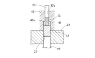
- a punch sleeve (corresponding to a sleeve of the present invention) 42 used in the primary molding step has a large-diameter hole portion in which a hole facing the opening portion 21 of the die 22 opens with the same inner diameter as the inner diameter of the opening portion 21 of the die 22.
- a two-stage structure of 43a (corresponding to the hole of the present invention) and a guide hole 43b having the same inner diameter as the outer diameter of the silver alloy wire 13 is formed in the back thereof.
- the space 44 is formed by the large-diameter hole 43 a substantially in communication with the opening 21 of the die 22 by causing the tip of the punch sleeve 42 to substantially contact the surface of the die 22.
- the base end portion of the copper alloy strand 12 is accommodated in the opening 21 of the die 22, and the distal end portion of the copper alloy strand 12 and the silver alloy strand 13 are the space portion of the punch sleeve 42. 44.
- the space portion 44 is filled while being crushed in the axial direction, and is expanded and joined to substantially the same outer diameter as the copper alloy strand 12.
- the copper alloy part 17 and the silver alloy part 18 are joined with substantially the same diameter as in the above-described one embodiment, and the joining interface 19 is formed substantially flat at right angles to the axial direction.
- one end portion including the bonding interface 19 between the copper alloy portion 17 and the silver alloy portion 18 is forged to form the flange portion 3.
- the punch sleeve 42 shown in FIGS. 9 and 10 is provided with a taper at the lower portion of the large-diameter hole 43a, and after the primary molding, when the punch 23 and the punch sleeve 42 are retracted, the primary molded body Applications such as easy removal of 15 are also possible.
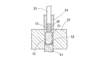
- the outer diameter of the copper alloy wire 12 is formed smaller than the inner diameter of the opening (hole) 21 of the die 22 of the molding die.
- a gap is formed between the die 22 and the copper alloy wire 12. This gap is set to such an extent that the copper alloy wire 12 can be smoothly inserted into the hole 21 of the die 22 in the primary forming step.
- the difference between the inner diameter of the hole 21 and the outer diameter of the copper alloy wire 12 is preferably set to 1/5 or less of the inner diameter of the hole 21.
- a concave portion 52 having a tapered peripheral edge is formed at the tip of the ejector pin 51.
- the copper alloy strand 12 When the copper alloy strand 12 is inserted into the hole 21 of the die 22, the copper alloy strand 12 can be guided into the recess 51 and placed in the center of the hole 21 of the die 22.
- symbol is attached
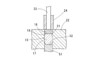
- the copper alloy strand 12 when the copper alloy strand 12 is inserted into the hole 21 of the die 22 and forged in a state where the silver alloy strand 13 is abutted, the copper alloy strand 12 becomes a gap between the hole 21 of the die 22. Although the diameter is expanded in the range, the inner peripheral surface of the hole 21 restrains the further diameter expansion, while the silver alloy wire 13 is expanded to the inner peripheral surface of the hole 21 while the copper alloy wire 12 is expanded. As shown in FIG. 12, the primary molded body 15 in which the copper alloy portion 17 and the silver alloy portion 18 are joined is formed.
- the copper alloy element wire 12 is forged in a state in which the diameter of the copper alloy wire 12 is limited by the inner peripheral surface of the hole 21, so that the joint interface 19 is formed substantially perpendicular to the axial direction. Can do. Thereafter, in the secondary forming step, one end portion including the bonding interface 19 between the copper alloy portion 17 and the silver alloy portion 18 is forged to form the flange portion 3.
- the outer diameter of the copper alloy wire 12 is formed to be smaller than the inner diameter of the opening (hole) 55 of the die 22 of the molding die.
- a gap is formed between the die 22 and the copper alloy wire 12. This gap is set to such an extent that the copper alloy wire 12 can be smoothly inserted into the hole 21 of the die 22 in the primary forming step.
- the difference between the inner diameter of the hole 21 and the outer diameter of the copper alloy wire 12 is preferably set to 1/5 or less of the inner diameter of the hole 21.
- a tapered surface 56 is formed below the hole 55 of the die 22, and an ejector pin insertion hole 57 is formed below the tapered surface 56.
- the tip surface of the ejector pin 25 is arranged at the lower end of the tapered surface 56 to form a recess together with the ejector pin.
- the copper alloy wire 12 can be guided into the recess and placed in the center of the hole 55 of the die 22.
- the hole 55 of the die 22 may have a straight shape as in the third embodiment, and a concave portion having a tapered peripheral edge may be formed at the tip of the ejector pin.
- symbol is attached
- the copper alloy strand 12 when the copper alloy strand 12 is inserted into the hole 55 of the die 22 and forged in a state where the silver alloy strand 13 is abutted, the copper alloy strand 12 is formed between the hole 55 and the punch 42 of the die 22.
- the diameter of the hole 43a is increased in the range of the gap with the hole 43a, but the inner diameter of the hole 55 and the hole 43a restrains the further diameter expansion.
- the silver alloy wire 13 extends to the inner periphery of the hole 43a.
- the primary molded body 15 in which the copper alloy portion 17 and the silver alloy portion 18 are joined is formed.
- the copper alloy element wire 12 is forged in a state where the diameter of the copper alloy wire 12 is limited by the inner peripheral surfaces of the hole 55 and the hole 43 a, so that the joint interface 19 is substantially flat at right angles to the axial direction. Can be formed. Thereafter, in the secondary forming step, one end portion including the bonding interface 19 between the copper alloy portion 17 and the silver alloy portion 18 is forged to form the flange portion 3.
- the forging deformation amount of the silver alloy wire 13 in the primary forming step is reduced, and the primary formed body 15 in a state where the diameter of the silver alloy portion 18 is smaller than the copper alloy portion 17,
- the secondary forming step also produced a composite contact that was cold forged by the same method as the method of the present invention. Also in FIG. 15, for convenience of explanation, the same reference numerals as those in the embodiment are given.
- each composite contact was set in a shear stress tester (TM2102D-IT manufactured by APTEC), a load was applied in parallel to the interface between the contact portion and the foot portion, the shear stress was measured, and the peel strength was measured.
- a shear stress tester T2102D-IT manufactured by APTEC
- a load was applied in parallel to the interface between the contact portion and the foot portion
- the shear stress was measured
- the peel strength was measured.
- two sets of composite contacts were assembled and fixed on a copper base metal plate with a thickness of 1 mm each, and this was attached to an ASTM contact switching tester and repeatedly opened and closed to evaluate cycle durability. did.
- the energizing conditions were a steady current of 24 A with a load load of 12 V DC and a 0.5 ⁇ resistive load, both contact force and opening force were 196 mN (20 gf), energizing 1 sec + resting 4 sec (cycle time 5 sec), 20 Opened and closed repeatedly up to 10,000 times. It should be noted that if the contact does not open for 1 second or more from the contact opening timing, it is determined that welding has occurred, and if welding has occurred a total of 10 times, the test is terminated even if the number of cycles is less than 200,000 times. .
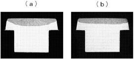
- the flow line of the material of a silver alloy part is a joining interface as it goes to a radial direction outer side from an axial center. It turns out that it curves greatly toward the outside. This is because in the secondary forming, the joint interface between the silver alloy part and the copper alloy part obtained by the primary forming cannot be expanded in the vicinity of the outer peripheral part of the collar part, and at the time of the primary forming, it was in an unjoined state.
- the side surface of the silver alloy part (wire outer peripheral surface) is joined to the end face (wire end face) of the outer peripheral part of the copper alloy part so as to buckle.
- the flow line is more uniform than in the comparative example, and the curvature from the bonding interface is smaller than that in the comparative example.
- the copper alloy part and the silver alloy part have already been joined over the entire surface at the time of primary forming, and this joint interface has been extended radially outwardly by the secondary forming.
- the silver alloy part and the copper alloy part are firmly joined from the outer part to the outer peripheral part of the collar part.
- this invention is not limited to the said embodiment, A various change can be added in the range which does not deviate from the meaning of this invention.
- the contact portion is provided only at one end portion, but a silver alloy may be provided at the end portion of the base portion, and the contact portion may be formed at both end portions.
- the composite contact of the present invention can be used as an electrical contact used in relays, switches, electromagnetic switches, breakers and the like.
Landscapes
- Engineering & Computer Science (AREA)
- Mechanical Engineering (AREA)
- Manufacturing & Machinery (AREA)
- Chemical & Material Sciences (AREA)
- Composite Materials (AREA)
- Materials Engineering (AREA)
- Forging (AREA)
- Manufacture Of Switches (AREA)
- Contacts (AREA)
Abstract
Description
本願は、2011年06月24日に日本に出願された特願2011-141053号及び2012年01月13日に中華人民共和国に出願された特許出願201210010406.9に基づき優先権を主張し、これらの内容をここに援用する。
特許文献1には、銅合金素線と銀合金素線とを同心状に突き合わせた状態で、ラッパ状に拡径した開口部を有する金型で両素線の突き合わせ部を圧接しながら外側方に膨出させるように予備成形した後、据え込み鍛造によりリベット形状に二次(仕上げ)成形する技術が開示されている。
このような突き合わせによる接合の場合、成形後の外周部において銀合金と銅合金の接合強度が低下し易く、接点として使用中に発生する熱応力により剥離し、耐久性の低下につながることが懸念される。そのため、これを回避するため、最終形状の外径よりも大きく拡げて成形した後、外周部の接合強度が弱い部分を除去し、接合強度に優れた中央部分のみを利用する方法も提案されている(特許文献2)。
また、各特許文献記載の技術では、銅合金及び銀合金の両素線とも同一径の素線を使用しているが、銅合金に対して銀合金の使用量が少ないことから、素線の切断や接合加工を容易にするため、銀合金素線として銅合金素線よりも小径のものを使用することが行われてきている。この異径素線を接合する場合、従来の接合方法では、ますます接合部の外周部が接合不十分となる傾向にあり、無駄が多くなる。また、鍛造初期に小径の銀合金が銅合金にめり込む変形となるため、平坦な接合界面を形成することが難しい。
本発明は、かかる知見の下、以下の解決手段とした。
あるいは、前記成形金型には、ダイの開口部を延長するように該開口部と同じ内径のスリーブが設けられるとともに、前記孔は前記スリーブにより形成されており、前記ダイの前記開口部内に前記銅合金素線の少なくとも基端部を挿入状態に収容しておき、前記スリーブの前記孔内で前記銀合金素線と前記銅合金素線とを鍛造することとしてもよい。
いずれの方法においても、銅合金素線の拡径を制限した状態で銀合金素線を鍛造してダイの孔又はスリーブの孔の内径まで拡げながら接合することができ、その後の二次成形工程における変形量を大きくすることができる。なお、銅合金素線の拡径を成形金型の孔の内周面により制限した状態とは、銅合金素線外周面と成形金型の孔の周面の間に生じる隙間の分だけ銅合金素線が拡径することを許容する。つまり、銅合金素線と、この銅合金素線よりも外径の小さい銀合金素線とを成形金型の孔内で突き合わせた状態で鍛造したとき、鍛造後の銅合金素線の外周面が成形金型の孔の内周面に接触して孔の内径以上に拡径しなければよい。
成形金型のダイの開口部の内径が銅合金素線の外径より大きい場合には、銅合金素線を成形金型のダイの開口部の中央に配置するために、開口部内で銅合金素線の下端を当接するエジェクターピンの先端部に周縁部をテーパー面とした形状の凹部を形成しておいてもよい。
本実施形態の複合接点1は、図1に示すように、小径の基部2の一端部に大径の鍔部3が形成された全体としてリベット形状をしているとともに、鍔部3の上面部を構成する銀合金からなる接点部4と、接点部4の背面に位置し、それと接合された鍔部3の下面部を構成する大径部5を基部2と一体に形成した銅合金からなる足部6とを有している。符号7は接点部4と足部6との接合界面を示す。
これら接点部4と足部6とは、銀合金からなる線材と銅合金からなる線材とを突き合わせて冷間でヘッダ加工することにより圧接される。圧接後に300℃~400℃の熱処理が施される。そして、鎖線で示すように、銅又は銅合金等からなる台金板8の孔9内に足部6の基部2を挿入した状態にかしめられる。
また、足部6を構成する銅合金としては、タフピッチ銅、無酸素銅などの純銅材に加えて、Cu-Co-P-Ni-Sn-Zn系合金、Cu-Zr系合金、Cu-Zr-Cr系合金、Cu-Cr系合金、Cu-Fe-P系合金などの析出強化型銅合金やCu-Mg系合金などの固溶強化型銅合金を用いることができる。
接点形状及び接合界面7の界面の所望形態に応じて、銅合金及び銀合金のビッカース硬さを適切に選択することにより、接合時に銅合金を大きく変形させるとともに、その銅合金の外周部まで銀合金層を十分に広げることができ、両者の接合強度を向上させることができる。
図2は製造時に使用される成形金型を示している。この成形金型11は、所定長さに切断した銅合金素線12及び銀合金素線13を接合する一次成形工程と、一次成形体15の接合部分を成形する二次成形工程とを同一のステーションにおいて、一次成形で使用されるパンチ23及びパンチスリーブ24と、二次成形で使用されるパンチ33とを交替しながら連続的に成形する金型である。
この複合接点1を製造する場合、銅合金素線12は、複合接点1の足部6と略同じ外径か又は小さい外径のものが用いられるが、銀合金素線13は、その使用量が少ないため、銅合金素線12と同じ外径とすると、長さが短すぎて、素材のせん断加工やクランプ等の取り扱いが困難になるので、銅合金素線12よりも小径のものが用いられる。これら銅合金素線12及び銀合金素線13は複合接点1で用いられる体積に応じて所定長さに切断された後、クランプ等により把持されて移送される。
図3~図8は、この成形金型11を使用した複合接点の製造方法を工程順に説明している。以下では、これら図3~図8を参照し、成形金型11についても説明しながら、製造方法を工程順に説明する。
一次成形工程では、銅合金素線12を挿入状態に収容する開口部(本発明の孔に相当しており、以下、第1実施形態においては孔という)21を有するダイ22と、この孔21内の銅合金素線12の先端に銀合金素線13を軸方向に押し込むように鍛造するパンチ23と、このパンチ23の外側にスライド可能に設けられたパンチスリーブ24と、ダイ22の孔21内をスライド可能かつ所定位置で静止・保持する機能を有するエジェクタ-ピン25とを備えている。エジェクタ-ピン25は、一次成形及び二次成形では、それぞれ所定位置で保持し、鍛造金型の一部を形成し、二次成形終了後には成形された複合接点1を孔21から排出する機能を備えている。
二次成形工程では、図7に示すように、一次成形工程で使用されたパンチ23及びパンチスリーブ24に代えて、ダイ22の孔21の直上にパンチ33が配置され、孔21から突出する銅合金部17と銀合金部18との接合界面19を含む一端部(銀合金部側の端部)を鍛造する。このパンチ33は、その先端面にダイ22の孔21の内径より大きい内径の凹部34が形成されており、この凹部34により鍔部3が形成される。
したがって、この二次成形工程においては、銅合金部17と銀合金部18との接合界面19は新生面を形成しながら拡径するとともに、その新生面に常に圧力が作用することになるから、鍔部3の外周縁に至るまで強固な接合界面7を得ることができる。また、一次成形体15における接合界面19が軸方向に直角で平坦に形成されていたことから、二次成形品の接合界面7も平坦に形成され、ほぼ一様な厚さの接点部4を得ることができる。
この一次成形工程で用いられるパンチスリーブ(本発明のスリーブに相当)42は、ダイ22の開口部21に対向する孔が、ダイ22の開口部21の内径と同じ内径で開口する大径孔部(本発明の孔に相当する)43aと、その奥に銀合金素線13の外径と同じ内径のガイド孔部43bとの二段構造とされている。そして、このパンチスリーブ42の先端をダイ22の表面に実質的に当接させることで、ダイ22の開口部21と実質的に連通状態の大径孔部43aにより空間部44が形成される。この場合、銅合金素線12は、その基端部がダイ22の開口部21内に挿入状態に収容され、銅合金素線12の先端部及び銀合金素線13がパンチスリーブ42の空間部44内に配置される。そして、その空間部44内で銀合金素線13を鍛造することにより、軸方向に押しつぶしながら空間部44内を充満させ、銅合金素線12と実質的に同じ外径まで拡げて接合する。得られた一次成形体は、前述の一実施形態と同様、銅合金部17と銀合金部18とがほぼ同じ径で接合され、接合界面19は、軸方向に直角でほぼ平坦に形成される。その後、上記二次成形工程によって、銅合金部17と銀合金部18との接合界面19を含む一端部を鍛造して鍔部3が形成される。
この実施形態では、エジェクタ-ピン25は、一次成形工程と二次成形工程とでその位置が変わらないため、エジェクタ-ピン25の位置変更が設備上難しい場合などに有効である。さらに、上記以外にも、例えば図9及び図10に示されるパンチスリーブ42について、大径孔部43a下部にテーパーを設け、一次成形後、パンチ23及びパンチスリーブ42が退避する際に一次成形体15の抜けを容易にするなどの応用も可能である。
また、エジェクタ-ピン51の先端部には、周縁部をテーパー面とした形状の凹部52が形成されており、銅合金素線12をダイ22の孔21に挿入したときに、銅合金素線12を凹部51内に案内してダイ22の孔21の中央に配置することができるようになっている。
その他、第1実施形態と共通部分には同一符号を付して説明を省略する。
この一次成形体15においても、銅合金素線12の拡径が孔21の内周面により制限された状態で鍛造されるので、その接合界面19を軸方向に直角でほぼ平坦に形成することができる。その後、上記二次成形工程によって、銅合金部17と銀合金部18との接合界面19を含む一端部を鍛造して鍔部3が形成される。
また、ダイ22の孔55の下部には、テーパー面56が形成され、このテーパー面56より下方にエジェクタ-ピン挿入孔57が形成されている。そして、テーパー面56の下端にエジェクターピン25の先端面が配置されることにより、このエジェクタ-ピンとともに凹部を形成しており、銅合金素線12をダイ22の孔55に挿入したときに、銅合金素線12を凹部内に案内してダイ22の孔55の中央に配置することができるようになっている。
また、ダイ22の孔55を第3実施形態と同様にストレート形状とし、エジェクタ-ピンの先端部に、周縁部をテーパー面とした形状の凹部を形成してもよい。
その他、第2実施形態と共通部分には同一符号を付して説明を省略する。
この一次成形体15においても、銅合金素線12の拡径が孔55および孔43aの内周面により制限された状態で鍛造されるので、その接合界面19を軸方向に直角でほぼ平坦に形成することができる。その後、上記二次成形工程によって、銅合金部17と銀合金部18との接合界面19を含む一端部を鍛造して鍔部3が形成される。
剥離強度は、各複合接点をせん断応力試験機(APTEC製 TM2102D-IT )にセットし、接点部と足部との界面に平行に荷重を加えてせん断応力を測定し、剥離強度を測定した。
耐久性評価は、作製した複合接点を2個一組としてそれぞれ厚み1mmの銅製の台金板にかしめ固定し、これをASTM接点開閉試験機に取り付けて繰り返し開閉し、サイクル耐久性の評価を実施した。通電条件は、負荷電圧が直流12V、0.5Ωの抵抗負荷による定常電流24Aとし、接触力、開離力とも196mN(20gf)で、通電1秒+休止4秒(サイクルタイム5秒)で20万回まで繰り返し開閉した。
なお、接点開離タイミングから1秒以上、接点が開かない場合には溶着したと判断し、合計で10回溶着が起きた場合にはサイクル数が20万回に満たない場合でも試験終了とした。
その判定基準としては、銀合金と銅合金の界面に目立った剥離が起きておらず、かつ、接点の鍔部がかしめ固定された銅板に接触している、もしくはかしめ固定された初期状態から外観上ほとんど変化がない場合には◎、銀合金と銅合金の界面での剥離が若干見られる、もしくは鍔部の反り上がりが観察されるものの、所定のサイクル数終了まで溶着停止しなかったものを○、銀合金と銅合金の界面での剥離が見られるか、鍔部の反り上がりが発生しており、所定のサイクル数に達する前に溶着停止を起こしてしまったものを×とした。

したがって、本発明の製造方法によれば、長期に亘り安定した接点性能を発揮する耐久性に優れた複合接点が得られることが確認された。
これに対して、同図(b)に示す実施例の場合は、比較例のものと比べるとフローラインが均質で、接合界面からの湾曲も比較例のものより小さい。これは、一次成形の時点で既に銅合金部と銀合金部とが全面で接合しており、この接合界面が二次成形によって均質に半径方向外方に延びているためであり、接合界面中心部から鍔部の外周部まで銀合金部と銅合金部とが強固に接合している。
例えば、上記実施形態では、一端部にのみ接点部が設けられているものとしたが、基部の端部にも銀合金を設けて、両端部に接点部を形成してもよい。
2 基部
3 鍔部
4 接点部
5 大径部
6 足部
7 接合界面
8 台金板
9 孔
11 成形金型
12 銅合金素線
13 銀合金素線
15 一次成形体
17 銅合金部
18 銀合金部
19 接合界面
21 開口部(孔)
22 ダイ
23 パンチ
24 パンチスリーブ
25 エジェクタ-ピン
26 空間部
33 パンチ
34 凹部
42 パンチスリーブ(スリーブ)
43a 大径孔部(孔)
43b ガイド孔部
44 空間部
51 エジェクタ-ピン
52 凹部
55 開口部(孔)
56 テーパー面
57 エジェクタ-ピン
Claims (5)
- 小径の基部の一端部に大径の鍔部が形成されるとともに、該鍔部の上面部を構成する銀合金からなる接点部と、該接点部の背面と接合した状態で前記鍔部の下面部を構成する大径部と前記小径の基部とを一体に形成した銅合金からなる足部とを有する複合接点を製造する方法であって、銅合金素線と、該銅合金素線よりも外径の小さい銀合金素線とを成形金型の孔内で突き合わせた状態で鍛造することにより、前記銅合金素線の拡径を前記孔の内周面により制限した状態で前記銀合金素線の外径を前記孔の内径まで拡げながら前記銀合金素線と前記銅合金素線とを接合して銀合金部と銅合金部とからなる一次成形体を形成する一次成形工程と、前記一次成形体の前記銀合金部、前記銀合金部と前記銅合金部との接合界面及び前記銅合金部を含む一端部を鍛造して前記鍔部を成形する二次成形工程とを有することを特徴とする複合接点の製造方法。
- 前記孔は前記成形金型のダイの開口部により形成されており、前記一次成形工程は、前記孔内に、該孔の開口端部に空間部を残して前記銅合金素線を挿入状態に収容しておき、前記空間部内で前記銀合金素線と前記銅合金素線とを鍛造することを特徴とする請求項1記載の複合接点の製造方法。
- 前記成形金型には、ダイの開口部を延長するように該ダイの開口部と同じ内径のスリーブが設けられるとともに、前記孔は前記スリーブにより形成されており、前記一次成形工程は、前記ダイの前記開口部内に前記銅合金素線の少なくとも基端部を挿入状態に収容しておき、前記スリーブの前記孔内で前記銀合金素線と前記銅合金素線とを鍛造することを特徴とする請求項1記載の複合接点の製造方法。
- 前記孔は前記銅合金素線の外径とほぼ同じ内径に形成されていることを特徴とする請求項1~3のいずれか一項に記載の複合接点の製造方法。
- 前記孔は前記銅合金素線の外径よりも大きくかつ前記大径部の外径より小さい内径に形成されていることを特徴とする請求項1~3のいずれか一項に記載の複合接点の製造方法。
Priority Applications (3)
| Application Number | Priority Date | Filing Date | Title |
|---|---|---|---|
| KR1020147001961A KR20140043130A (ko) | 2011-06-24 | 2012-06-21 | 복합 접점의 제조 방법 |
| EP12802401.5A EP2725598A4 (en) | 2011-06-24 | 2012-06-21 | METHOD FOR PRODUCING A COMPOSITE CONTACT |
| US14/127,738 US20140201999A1 (en) | 2011-06-24 | 2012-06-21 | Method of manufacturing composite contact |
Applications Claiming Priority (4)
| Application Number | Priority Date | Filing Date | Title |
|---|---|---|---|
| JP2011141053 | 2011-06-24 | ||
| JP2011-141053 | 2011-06-24 | ||
| CN201210010406.9 | 2012-01-13 | ||
| CN2012100104069A CN102842448A (zh) | 2011-06-24 | 2012-01-13 | 复合触点的制造方法 |
Publications (1)
| Publication Number | Publication Date |
|---|---|
| WO2012176843A1 true WO2012176843A1 (ja) | 2012-12-27 |
Family
ID=47369707
Family Applications (1)
| Application Number | Title | Priority Date | Filing Date |
|---|---|---|---|
| PCT/JP2012/065870 Ceased WO2012176843A1 (ja) | 2011-06-24 | 2012-06-21 | 複合接点の製造方法 |
Country Status (7)
| Country | Link |
|---|---|
| US (1) | US20140201999A1 (ja) |
| EP (1) | EP2725598A4 (ja) |
| JP (1) | JP2013030475A (ja) |
| KR (1) | KR20140043130A (ja) |
| CN (1) | CN102842448A (ja) |
| TW (1) | TW201324561A (ja) |
| WO (1) | WO2012176843A1 (ja) |
Cited By (2)
| Publication number | Priority date | Publication date | Assignee | Title |
|---|---|---|---|---|
| TWI630624B (zh) * | 2016-11-03 | 2018-07-21 | 財團法人國家同步輻射研究中心 | 高熱負載真空裝置及其製造方法 |
| CN109317797A (zh) * | 2018-12-03 | 2019-02-12 | 镇江米青机电有限公司 | 一种正畸托槽焊接用定位装置 |
Families Citing this family (11)
| Publication number | Priority date | Publication date | Assignee | Title |
|---|---|---|---|---|
| WO2014092173A1 (ja) * | 2012-12-14 | 2014-06-19 | 田中貴金属工業株式会社 | リベット型接点及びその製造方法 |
| JP2013239437A (ja) * | 2013-05-02 | 2013-11-28 | Tanaka Kikinzoku Kogyo Kk | リベット型接点及びその製造方法 |
| CN104240996B (zh) * | 2014-09-11 | 2016-08-03 | 南京东锐铂业有限公司 | 银钯触点的生产工艺 |
| CN104690195A (zh) * | 2014-11-26 | 2015-06-10 | 东莞市华诺合金有限公司 | 一种银脚铆钉的制造方法及加工装置 |
| CN104668687B (zh) * | 2015-01-30 | 2017-10-13 | 上海和伍复合材料有限公司 | 一种电触头的焊接方法 |
| WO2017204129A1 (ja) * | 2016-05-23 | 2017-11-30 | 田中貴金属工業株式会社 | 電気接点用のクラッド材及び該クラッド材の製造方法 |
| CN108231459A (zh) * | 2018-01-05 | 2018-06-29 | 万沙电气有限公司 | 一种接插件触头成型工艺 |
| DE102020209161B3 (de) | 2020-07-21 | 2021-11-18 | Vitesco Technologies Germany Gmbh | Leistungsschalter zur Anordnung in einer Schaltsicherungsbox und Schaltsicherungsbox für ein Kraftfahrzeug |
| CN117558571B (zh) * | 2023-11-07 | 2024-07-30 | 贵研中希(上海)新材料科技有限公司 | 一种双切环型三复合铆钉电触头及其制造方法 |
| KR102633361B1 (ko) | 2023-11-16 | 2024-02-05 | (주)동광특수금속 | 복합 구조를 가지는 리벳형 접점구 |
| CN120527196B (zh) * | 2025-07-23 | 2025-11-25 | 温州梓耀电气有限公司 | 一种断路器引弧结构的制作方法 |
Citations (5)
| Publication number | Priority date | Publication date | Assignee | Title |
|---|---|---|---|---|
| JPS6037620A (ja) * | 1983-08-08 | 1985-02-27 | 有限会社相原製作所 | 複合接点の成形方法 |
| JPS61121214A (ja) | 1984-11-16 | 1986-06-09 | 田中貴金属工業株式会社 | リベツト型クラツド接点の製造方法 |
| JPH0197331A (ja) * | 1987-10-08 | 1989-04-14 | Tanaka Kikinzoku Kogyo Kk | リベット型電気接点の加工方法 |
| JPH044529A (ja) * | 1990-04-23 | 1992-01-09 | Tsunetoshi Suzuki | 複合冷間圧着塑性加工法 |
| JPH04298927A (ja) | 1991-03-27 | 1992-10-22 | Tanaka Kikinzoku Kogyo Kk | リベット型電気接点の製造方法 |
Family Cites Families (7)
| Publication number | Priority date | Publication date | Assignee | Title |
|---|---|---|---|---|
| US3026603A (en) * | 1958-10-13 | 1962-03-27 | Kelsey Hayes Co | Method of making electrical contacts and the like |
| FR1243746A (fr) * | 1959-12-29 | 1960-10-14 | Eugen Duerrwachter Doduco Fa D | Procédé et dispositif pour la fabrication continue d'objets de série en bimétal |
| JPS6038217B2 (ja) * | 1977-07-25 | 1985-08-30 | 中外電気工業株式会社 | 複合電気接点の製造装置 |
| JPS5673826A (en) * | 1979-11-22 | 1981-06-18 | Chugai Electric Ind Co Ltd | Method of manufacturing composite electric contact by cold solderless bonding |
| DE3112452C2 (de) * | 1981-03-28 | 1985-04-25 | Doduco KG Dr. Eugen Dürrwächter, 7530 Pforzheim | Verfahren zum Herstellen von Doppelkontaktnieten |
| JPS57181740A (en) * | 1981-04-30 | 1982-11-09 | Matsushita Electric Works Ltd | Manufacture of contact |
| JPS63241892A (ja) * | 1987-03-30 | 1988-10-07 | 藤好 克聡 | 端子等の製造方法 |
-
2012
- 2012-01-13 CN CN2012100104069A patent/CN102842448A/zh active Pending
- 2012-06-21 US US14/127,738 patent/US20140201999A1/en not_active Abandoned
- 2012-06-21 KR KR1020147001961A patent/KR20140043130A/ko not_active Withdrawn
- 2012-06-21 WO PCT/JP2012/065870 patent/WO2012176843A1/ja not_active Ceased
- 2012-06-21 JP JP2012139595A patent/JP2013030475A/ja active Pending
- 2012-06-21 EP EP12802401.5A patent/EP2725598A4/en not_active Withdrawn
- 2012-06-21 TW TW101122201A patent/TW201324561A/zh unknown
Patent Citations (5)
| Publication number | Priority date | Publication date | Assignee | Title |
|---|---|---|---|---|
| JPS6037620A (ja) * | 1983-08-08 | 1985-02-27 | 有限会社相原製作所 | 複合接点の成形方法 |
| JPS61121214A (ja) | 1984-11-16 | 1986-06-09 | 田中貴金属工業株式会社 | リベツト型クラツド接点の製造方法 |
| JPH0197331A (ja) * | 1987-10-08 | 1989-04-14 | Tanaka Kikinzoku Kogyo Kk | リベット型電気接点の加工方法 |
| JPH044529A (ja) * | 1990-04-23 | 1992-01-09 | Tsunetoshi Suzuki | 複合冷間圧着塑性加工法 |
| JPH04298927A (ja) | 1991-03-27 | 1992-10-22 | Tanaka Kikinzoku Kogyo Kk | リベット型電気接点の製造方法 |
Non-Patent Citations (1)
| Title |
|---|
| See also references of EP2725598A4 |
Cited By (3)
| Publication number | Priority date | Publication date | Assignee | Title |
|---|---|---|---|---|
| TWI630624B (zh) * | 2016-11-03 | 2018-07-21 | 財團法人國家同步輻射研究中心 | 高熱負載真空裝置及其製造方法 |
| CN109317797A (zh) * | 2018-12-03 | 2019-02-12 | 镇江米青机电有限公司 | 一种正畸托槽焊接用定位装置 |
| CN109317797B (zh) * | 2018-12-03 | 2024-03-15 | 乔斯生物(深圳)科技有限公司 | 一种正畸托槽焊接用定位装置 |
Also Published As
| Publication number | Publication date |
|---|---|
| TW201324561A (zh) | 2013-06-16 |
| EP2725598A1 (en) | 2014-04-30 |
| EP2725598A4 (en) | 2015-03-25 |
| US20140201999A1 (en) | 2014-07-24 |
| CN102842448A (zh) | 2012-12-26 |
| JP2013030475A (ja) | 2013-02-07 |
| KR20140043130A (ko) | 2014-04-08 |
Similar Documents
| Publication | Publication Date | Title |
|---|---|---|
| JP2013030475A (ja) | 複合接点の製造方法 | |
| CN111403075B (zh) | 一种镶嵌复合金属结构板带材、冲压件及其制造方法 | |
| TWI505304B (zh) | 鉚釘形接點及其製造方法 | |
| WO2017068974A1 (ja) | 端子用金属板、端子及び端子対 | |
| JP6280524B2 (ja) | 電気接点要素および電気接点要素を製造する方法 | |
| CN114512359A (zh) | 一种银金属氧化物镶嵌复合带材及其制备方法 | |
| KR100921704B1 (ko) | 판상형 복합 전기접점소자의 제조방법 | |
| JP5346607B2 (ja) | 端子及び端子と電線の接続方法 | |
| WO2014092173A1 (ja) | リベット型接点及びその製造方法 | |
| JP2003036898A (ja) | 全周加締め接続用端子とその接続方法 | |
| EP1515626B1 (en) | Method for manufacturing articles of jewellery | |
| JP2012221631A (ja) | 複合接点 | |
| CN111531100A (zh) | 一种新型的三冲式冷镦铆钉触头的加工方法 | |
| JPH0736298B2 (ja) | 電気接触体の製造方法 | |
| CN110050390A (zh) | 用于制造插口触头的方法 | |
| JPH08255528A (ja) | 三層接点製造ヘッダおよび三層接点製造方法 | |
| CN104900435A (zh) | 一种三复合铆钉的生产工艺 | |
| GB2406535A (en) | A press for cold forging an electrical contact | |
| JP3422941B2 (ja) | リング状部品の製造方法 | |
| KR20160071705A (ko) | 확산접합을 이용한 구리-은 합금계 전기접점의 제조방법 | |
| JPH0230131B2 (ja) | ||
| CN110010426B (zh) | 一种基于套筒镶嵌于铜棒的挤压式动触头 | |
| CN111727532A (zh) | 接触插头的制造方法以及接触插头 | |
| JP2025073296A (ja) | はんだこて先の製造方法 | |
| JP2025088421A (ja) | はんだこて先の製造方法 |
Legal Events
| Date | Code | Title | Description |
|---|---|---|---|
| 121 | Ep: the epo has been informed by wipo that ep was designated in this application |
Ref document number: 12802401 Country of ref document: EP Kind code of ref document: A1 |
|
| NENP | Non-entry into the national phase |
Ref country code: DE |
|
| WWE | Wipo information: entry into national phase |
Ref document number: 2012802401 Country of ref document: EP |
|
| ENP | Entry into the national phase |
Ref document number: 20147001961 Country of ref document: KR Kind code of ref document: A |
|
| WWE | Wipo information: entry into national phase |
Ref document number: 14127738 Country of ref document: US |