WO2012176868A1 - Système d'alimentation électrique - Google Patents
Système d'alimentation électrique Download PDFInfo
- Publication number
- WO2012176868A1 WO2012176868A1 PCT/JP2012/065962 JP2012065962W WO2012176868A1 WO 2012176868 A1 WO2012176868 A1 WO 2012176868A1 JP 2012065962 W JP2012065962 W JP 2012065962W WO 2012176868 A1 WO2012176868 A1 WO 2012176868A1
- Authority
- WO
- WIPO (PCT)
- Prior art keywords
- string
- power
- charge
- strings
- storage battery
- Prior art date
- Legal status (The legal status is an assumption and is not a legal conclusion. Google has not performed a legal analysis and makes no representation as to the accuracy of the status listed.)
- Ceased
Links
Images




Classifications
-
- H—ELECTRICITY
- H01—ELECTRIC ELEMENTS
- H01M—PROCESSES OR MEANS, e.g. BATTERIES, FOR THE DIRECT CONVERSION OF CHEMICAL ENERGY INTO ELECTRICAL ENERGY
- H01M10/00—Secondary cells; Manufacture thereof
- H01M10/42—Methods or arrangements for servicing or maintenance of secondary cells or secondary half-cells
- H01M10/44—Methods for charging or discharging
- H01M10/441—Methods for charging or discharging for several batteries or cells simultaneously or sequentially
-
- H—ELECTRICITY
- H01—ELECTRIC ELEMENTS
- H01M—PROCESSES OR MEANS, e.g. BATTERIES, FOR THE DIRECT CONVERSION OF CHEMICAL ENERGY INTO ELECTRICAL ENERGY
- H01M10/00—Secondary cells; Manufacture thereof
- H01M10/04—Construction or manufacture in general
- H01M10/0445—Multimode batteries, e.g. containing auxiliary cells or electrodes switchable in parallel or series connections
-
- H—ELECTRICITY
- H01—ELECTRIC ELEMENTS
- H01M—PROCESSES OR MEANS, e.g. BATTERIES, FOR THE DIRECT CONVERSION OF CHEMICAL ENERGY INTO ELECTRICAL ENERGY
- H01M10/00—Secondary cells; Manufacture thereof
- H01M10/42—Methods or arrangements for servicing or maintenance of secondary cells or secondary half-cells
- H01M10/425—Structural combination with electronic components, e.g. electronic circuits integrated to the outside of the casing
-
- H—ELECTRICITY
- H02—GENERATION; CONVERSION OR DISTRIBUTION OF ELECTRIC POWER
- H02J—ELECTRIC POWER NETWORKS; CIRCUIT ARRANGEMENTS OR SYSTEMS FOR SUPPLYING OR DISTRIBUTING ELECTRIC POWER; SYSTEMS FOR STORING ELECTRIC ENERGY
- H02J7/00—Circuit arrangements for charging or discharging batteries or for supplying loads from batteries
- H02J7/50—Circuit arrangements for charging or discharging batteries or for supplying loads from batteries acting upon multiple batteries simultaneously or sequentially
- H02J7/575—Parallel/serial switching of connection of batteries to charge or load circuit
-
- H—ELECTRICITY
- H01—ELECTRIC ELEMENTS
- H01M—PROCESSES OR MEANS, e.g. BATTERIES, FOR THE DIRECT CONVERSION OF CHEMICAL ENERGY INTO ELECTRICAL ENERGY
- H01M10/00—Secondary cells; Manufacture thereof
- H01M10/42—Methods or arrangements for servicing or maintenance of secondary cells or secondary half-cells
- H01M10/48—Accumulators combined with arrangements for measuring, testing or indicating the condition of cells, e.g. the level or density of the electrolyte
- H01M10/482—Accumulators combined with arrangements for measuring, testing or indicating the condition of cells, e.g. the level or density of the electrolyte for several batteries or cells simultaneously or sequentially
-
- H—ELECTRICITY
- H01—ELECTRIC ELEMENTS
- H01M—PROCESSES OR MEANS, e.g. BATTERIES, FOR THE DIRECT CONVERSION OF CHEMICAL ENERGY INTO ELECTRICAL ENERGY
- H01M10/00—Secondary cells; Manufacture thereof
- H01M10/42—Methods or arrangements for servicing or maintenance of secondary cells or secondary half-cells
- H01M10/425—Structural combination with electronic components, e.g. electronic circuits integrated to the outside of the casing
- H01M2010/4271—Battery management systems including electronic circuits, e.g. control of current or voltage to keep battery in healthy state, cell balancing
-
- Y—GENERAL TAGGING OF NEW TECHNOLOGICAL DEVELOPMENTS; GENERAL TAGGING OF CROSS-SECTIONAL TECHNOLOGIES SPANNING OVER SEVERAL SECTIONS OF THE IPC; TECHNICAL SUBJECTS COVERED BY FORMER USPC CROSS-REFERENCE ART COLLECTIONS [XRACs] AND DIGESTS
- Y02—TECHNOLOGIES OR APPLICATIONS FOR MITIGATION OR ADAPTATION AGAINST CLIMATE CHANGE
- Y02E—REDUCTION OF GREENHOUSE GAS [GHG] EMISSIONS, RELATED TO ENERGY GENERATION, TRANSMISSION OR DISTRIBUTION
- Y02E60/00—Enabling technologies; Technologies with a potential or indirect contribution to GHG emissions mitigation
- Y02E60/10—Energy storage using batteries
-
- Y—GENERAL TAGGING OF NEW TECHNOLOGICAL DEVELOPMENTS; GENERAL TAGGING OF CROSS-SECTIONAL TECHNOLOGIES SPANNING OVER SEVERAL SECTIONS OF THE IPC; TECHNICAL SUBJECTS COVERED BY FORMER USPC CROSS-REFERENCE ART COLLECTIONS [XRACs] AND DIGESTS
- Y02—TECHNOLOGIES OR APPLICATIONS FOR MITIGATION OR ADAPTATION AGAINST CLIMATE CHANGE
- Y02P—CLIMATE CHANGE MITIGATION TECHNOLOGIES IN THE PRODUCTION OR PROCESSING OF GOODS
- Y02P80/00—Climate change mitigation technologies for sector-wide applications
- Y02P80/10—Efficient use of energy, e.g. using compressed air or pressurized fluid as energy carrier
Definitions
- the present invention relates to a power supply system including a plurality of parallel storage batteries.
- Such a power supply system can discharge the storage battery (supply power) at an arbitrary timing by charging the storage battery in advance (consuming power). That is, by controlling the charging and discharging timing of the storage battery, it is possible to control the timing of consuming grid power (power supplied from the power company).
- the grid electricity charge includes a fixed basic charge and a pay-per-use charge.
- the electric power company sets the basic charge so that the basic charge becomes cheaper as the maximum value of the amount of grid power consumed per unit time becomes smaller.
- the usage fee is set so that the price per unit power of the usage fee is lower at night when the power consumption is lower than during the day when the power consumption is high. Therefore, the user who uses the system power can reduce the power charge of the system power as the consumption of the system power is leveled.
- a user who uses the grid power to charge the storage battery using grid power during a time zone when the power demand of the grid power user is small or a nighttime electricity rate is applied
- the power charge of the grid power can be suppressed by supplementing the power (the hatched portion shown in FIG. 1) that exceeds the predetermined threshold with the discharge of the storage battery. it can.
- the power supply system has a configuration in which a plurality of strings in which a storage battery and a power conversion device are connected in series are connected in parallel, and the output of the power conversion device changes according to a charge / discharge request to the power supply system.
- Power converters generally have a characteristic that conversion efficiency decreases at low output. Therefore, for example, in Patent Document 1, in order to mitigate a decrease in conversion efficiency at the time of low output of the power converter, a plurality of inverters (power converters) are provided, the number of inverters used is limited, and the inverters are highly efficient. It is made to operate with.
- an object of the present invention is to provide a power supply system having a wide range of input / output power that can be operated with high efficiency.
- a power supply system includes a plurality of strings in which a storage battery and a power converter are connected in series, includes a control unit that controls the power converter of each string, A power supply system in which the strings are connected so that the storage batteries are connected in parallel, wherein the control unit is based on a charge / discharge request required from the outside, and at least the charge / discharge efficiency of the storage battery
- the control unit is based on a charge / discharge request required from the outside, and at least the charge / discharge efficiency of the storage battery
- the power allocated to each of the plurality of strings so that the charge / discharge efficiency of the entire system is at or near the maximum. It is assumed that the distribution (first configuration) is determined. Note that at least a part of the control unit may be incorporated in the storage battery.
- the charge / discharge efficiency of the string calculated by adding at least the charge / discharge conversion efficiency of the power converter to the charge / discharge efficiency of the storage battery based on the charge / discharge request required from the outside is considered. Since the distribution of power allocated to each of the strings is determined so that the charge / discharge efficiency of the entire system is at or near the maximum, the range of input / output power that can be operated with high efficiency is wide. Become.
- FIG. 1 It is a figure which shows the typical example of the electric power demand of the user who utilizes grid power. It is a figure showing a schematic structure of an electric power supply system concerning one embodiment of the present invention. It is a figure which shows an example of the charging / discharging efficiency characteristic of the storage battery 3, the charging / discharging efficiency characteristic of PCS2, and the charging / discharging efficiency characteristic of a string. It is a figure which shows the example of a change of the combination of the string in which the electric power allocated is zero, and the string in which the electric power allocated is not zero. It is a figure which shows the charging / discharging efficiency characteristic of the whole electric power supply system which concerns on one Embodiment of this invention shown in FIG. It is a figure which shows the example of distribution of the value of the charging / discharging request
- FIG. 2 is a block diagram showing a schematic configuration of a power supply system according to an embodiment of the present invention.
- thick lines connecting the blocks indicate power lines
- thin lines connecting the blocks indicate communication lines.
- each communication line is realized by wired communication from the viewpoint of emphasizing reliability, but can also be realized by wireless communication. Further, the communication may be performed by, for example, TCP (Transmission Control Protocol).
- TCP Transmission Control Protocol
- the power supply system includes a PCS (Power Conditioning System) management control unit 1, a first string in which the PCS 2A and the storage battery 3A are connected in series, and the PCS 2B and the storage battery 3B in series.
- a second string connected, a third string connecting PCS2C and storage battery 3C in series, a fourth string connecting PCS2D and storage battery 3D in series, a fifth string connecting PCS2E and storage battery 3E in series, and BMU (Battery Management Unit) 4A-4E and master BMU5.
- the first to fifth strings are connected via the PCS management control unit 1 so that the storage batteries 3A to 3E are connected in parallel.
- the PCS management control unit 1, the BMUs 4A to 4E, the master BMU 5, and a part of each of the storage batteries 3A to 3E correspond to an example of a “control unit” recited in the claims.
- the PCSs 2A to 2E may be referred to as PCS2 when individual division is unnecessary.
- it may be referred to as storage battery 3, string, or BMU4.
- the PCS management control unit 1 is connected to an external load 100 and a power system 200.
- the load 100 is a load having an AC power input terminal
- the power system 200 is a power system that supplies AC power.
- the PCS management control unit 1 controls the operations of the PCSs 2A to 2E based on the charge / discharge command from the master BMU 5, and monitors the states of the PCSs 2A to 2E.
- Each of the PCSs 2A to 2E is a bidirectional AC / DC power converter, which converts AC power supplied from the power system 200 via the PCS management control unit 1 during charging into DC power during charging, and belongs to the same string during discharging. DC power supplied from the storage battery 3 is converted into AC power.
- the PCS management control unit 1 when the PCS management control unit 1 is connected to an external DC load (a load having a DC power input terminal) and a DC power source (for example, a solar cell), the PCS 2A to 2E are bidirectional. What is necessary is just to change to a DC / DC power converter.
- the form of the storage batteries 3A to 3E is not particularly limited, and may be, for example, a single battery cell, a battery pack that is an assembly of a plurality of battery cells, or a plurality of the battery packs connected. It may be what you did.
- As a form of connecting a plurality of battery packs there are a plurality of battery pack strings in which a plurality of battery packs are connected in series in one storage battery, and the plurality of battery pack strings are connected in parallel, all in one storage battery. Are connected in series, and all battery packs are connected in parallel in one storage battery.
- a plurality of battery packs may be connected in series.
- the battery pack may include, for example, a battery state detection unit, a battery pack control unit, and a communication unit in addition to the plurality of battery cells.
- the battery state detection unit detects, for example, the voltage value of each stage where battery cells are connected in parallel, and the current value and voltage value between the + and-electrodes of the battery pack, the remaining capacity of the battery pack, The temperature is detected, and the detected data is output to the battery pack controller.
- the remaining capacity of the battery pack is obtained from the integrated value of the charge / discharge current flowing through the battery pack, and is a calculation formula or table showing the relationship between the predetermined open circuit voltage (OCV) of the battery pack and the remaining capacity. Can be obtained by referring to.
- the battery pack control unit transmits detection data acquired from the battery state detection unit as battery data to the BMU 4 via the communication unit.
- Each of the BMUs 4A to 4E monitors the state of the storage battery 3 belonging to the same string, and transmits log information regarding the state of the storage battery 3 belonging to the same string, the state of itself (BMU 4), etc. to the master BMU 5.
- the master BMU 5 monitors and controls the storage batteries 3A to 3E and BMU 4A to 4E in an integrated manner.
- the master BMU 5 transmits a charge / discharge command to the PCS management control unit 1 based on a charge / discharge request sent from the outside.
- the master BMU 5 receives a charge / discharge request sent from the outside.
- the PCS management control unit 1 receives a charge / discharge request sent from the outside, and the master BMU 5
- information regarding the state of the storage batteries 3A to 3E may be sent to the PCS management control unit 1.
- FIG. 3 shows an example of the charge / discharge efficiency characteristics of the storage battery 3, the charge / discharge efficiency characteristics of the PCS 2, and the charge / discharge efficiency characteristics of the string.
- T1 shows the charge / discharge efficiency characteristic of the storage battery 3
- T2 shows the charge / discharge efficiency characteristic of PCS2
- T3 shows the charge / discharge efficiency characteristic of the string.
- the charging / discharging efficiency of the string is a value obtained by multiplying the charging / discharging efficiency of the storage battery 3 by the charging / discharging efficiency of the PCS 2.
- the input / output power rating of the string is 60 kW.
- the maximum value of efficiency is during charge / discharge at 16 kW. Therefore, in order to increase the efficiency of the entire system, in response to a charge / discharge request to the power supply system according to the embodiment of the present invention shown in FIG. It is desirable to stop operation. Therefore, the power supply system according to the embodiment of the present invention shown in FIG. 2 performs the following control in consideration of the charge / discharge efficiency of the string so that the charge / discharge efficiency of the entire system is maximized. .
- Master BMU 5 assigns 16 kW to each of m (m is a natural number of 4 or less) strings and 0 kW to each of (5-m) strings based on a charge / discharge request sent from the outside.
- a charge / discharge command is created, and the charge / discharge command is sent to the PCS management control unit 1.
- the PCS management control unit 1 controls the PCSs 2A to 2E based on the charge / discharge command from the master BMU 5. For example, if the charge / discharge request to the power supply system according to the embodiment of the present invention shown in FIG. 2 is 16 kW, one of the first to fifth strings is charged / discharged at 16 kW, and the remaining 4 One string pauses operation. For example, if the charge / discharge request to the power supply system according to the embodiment of the present invention shown in FIG. 2 is 32 kW, two of the first to fifth strings are charged / discharged at 16 kW, and the rest The three strings cease operation.
- the master BMU 5 assigns 16 kW to the same number of strings as the quotient, and assigns the remainder to the strings assigned 16 kW in equal divisions, or assigns 16 kW to the same number of strings as the quotient and assigns no further 16 kW. Select either one of the strings to allocate all the remainder, or assign the charge / discharge request value to each number of strings that is one more than the quotient, and assign it to the selected power allocation.
- the charge / discharge command to be generated is created, and the charge / discharge command is sent to the PCS management control unit 1.
- the PCS management control unit 1 controls the PCSs 2A to 2E based on the charge / discharge command from the master BMU 5. For example, if the charge / discharge request to the power supply system according to the embodiment of the present invention shown in FIG. 2 is 18 kW, one of the first to fifth strings is charged / discharged at 18 kW, and the remaining 4 One string pauses operation, or one of the first to fifth strings is charged / discharged at 16 kW, and the other one of the first to fifth strings is charged / discharged at 2 kW, and the rest The three strings are either stopped or two of the first to fifth strings are charged / discharged at 9 kW, and the remaining three strings are selected to stop the operation. Execute.
- the charge / discharge request to the power supply system according to the embodiment of the present invention shown in FIG. 2 is 36 kW
- two of the first to fifth strings are charged / discharged at 18 kW
- the rest The three strings are suspended, or two of the first to fifth strings are charged and discharged at 16 kW, and the other one of the first to fifth strings is charged and discharged at 4 kW.
- Either the remaining three strings are suspended, or three of the first to fifth strings are charged / discharged at 12 kW, and the remaining two strings are suspended.
- Select and execute. Which of the three options is selected is determined by the quotient value, the remainder value, and the shape of the charge / discharge efficiency characteristics of the string, and the option with the highest overall system efficiency is selected from the three options.
- the master BMU 5 may calculate the efficiency of the entire system with respect to each of the three options at the time of execution of control, and select an option having the highest efficiency of the entire system among the three options.
- the efficiency of the entire system is calculated for each of the three options for each value of the discharge request, and the power distribution pattern corresponding to the option with the highest efficiency of the entire system among the three options is determined for each value of the master BMU 5 It may be stored in advance in an internal memory.
- the option having the highest efficiency of the entire system is selected from the above three options.
- the efficiency of the entire system may be increased depending on the charge / discharge request value.
- One or two of the above-mentioned three options may be abolished by allowing a slight decrease.
- the master BMU 5 divides the charge / discharge request sent from the outside into five equal parts, assigns them to each of the first to fifth strings, creates a charge / discharge instruction corresponding to the power assignment, and manages the charge / discharge instruction by PCS Send to control unit 1.
- Patent Document 1 Since the power supply system according to the embodiment of the present invention shown in FIG. 2 executes the above control, it is proposed in Patent Document 1 in a range where the input / output power that does not equally distribute the input / output power to each string is small. Thus, it is possible to operate with higher efficiency than determining the distribution of power to be assigned to each string in consideration of the efficiency of the power converter.
- Patent Document 1 when there is a 64 kW discharge request, according to the method proposed in Patent Document 1, it is assigned to be 50 to 60% of the rating (see Paragraph 0010 of Patent Document 1). Two of the five strings are charged / discharged at 32 kW, and the remaining three strings are out of operation, and the discharge efficiency of the entire system is about 90% (see FIG. 3).
- the power supply system according to an embodiment of the present invention shown in FIG. 2 four of the first to fifth strings are charged and discharged at 16 kW, and the remaining one string is operated.
- the overall discharge efficiency of the system is about 92.5% (see FIG. 3), and the efficiency of the entire system can be improved by about 2.5% compared to the method proposed in Patent Document 1. it can. Since this is a case where only discharge is taken into consideration, when considering the same at the time of charging, when there is a 64 kW discharge request and a 64 kW charge request, the charge / discharge efficiency depends on the method proposed in Patent Document 1.
- the invention can improve the overall system efficiency by about 4.6%.
- the effective remaining capacity of the power supply system according to the embodiment of the present invention shown in FIG. 2 is reduced.
- the remaining capacity of one of the first to fifth strings is 100 kWh and the remaining capacity of the remaining four strings is 275 kWh
- 300 kW 60 kW / string ⁇ 5 strings
- the remaining capacity of the first to fifth strings can be equalized by changing the combination of the string that stops operation and the string that does not stop operation at any timing.
- the arbitrary timing for changing the combination of the string that pauses the operation and the string that does not pause the operation may be, for example, a timing at regular intervals generated by the master BMU 5 using the timer.
- the charge / discharge request may be changed, and the master BMU 5 acquires the temperature information of each storage battery 3 from each BMU 4, and the master BMU 5 can grasp the temperature of the storage battery 3 based on the acquired temperature information or
- the timing at which the rate of temperature change exceeds the threshold may be used, or these timings may be combined.
- the timing at which the temperature or temperature change rate of the storage battery 3 exceeds the threshold is included in an arbitrary timing for changing the combination of the string that stops operation and the string that does not stop operation, the temperature or temperature change rate of the storage battery 3
- the threshold value exceeds the threshold value the string to which the storage battery 3 whose temperature or temperature change rate exceeds the threshold value belongs is changed from a string that does not pause operation to a string that pauses operation. Since the degree of progress of deterioration of the storage battery 3 increases as the temperature rises, the deterioration of the storage battery 3 can be suppressed by such a change.
- the temperature or the rate of temperature change of the storage battery 3 may be the average temperature of the storage battery 3 or the rate of change of the average temperature, but the storage battery 3 has a plurality of battery packs, and masters the temperature information of each battery pack. If the BMU 5 can be acquired, the maximum value of the temperature of each battery pack in the storage battery 3 or the maximum value of the temperature change rate of each battery pack in the storage battery 3 is set from the viewpoint of more reliably suppressing the deterioration of the storage battery 3. It is desirable.
- the master BMU 5 acquires the remaining capacity information of each storage battery 3 from each BMU 4, and is a string that pauses operation among the first to fifth strings.
- the combination of the string that stops the operation and the string that does not stop the operation is changed so that the remaining capacity of the storage battery 3 approaches evenly Then, the string to which the storage battery having a large capacity deterioration belongs is more rapidly deteriorated than the other strings.
- the BMU 4 causes the corresponding storage battery 3 to perform capacity learning, and the capacity deterioration of the corresponding storage battery 3 by the capacity learning.
- the master BMU 5 obtains the capacity deterioration degree information of each storage battery 3 from each BMU 4 and at least one of the first to fifth strings stops operation, the capacity deterioration of each storage battery 3 Based on the degree, the combination of the string that pauses the operation and the string that does not pause the operation is changed at an arbitrary timing so that the capacity deterioration degree of all the storage batteries 3 approaches equally.
- the frequency at which a string to which a storage battery with a large capacity deterioration belongs is set to a string that does not stop operation is reduced.
- the change of the combination of the string that stops the operation for evenly reducing the capacity deterioration degree of all the storage batteries 3 and the string that does not stop the operation is to make the remaining capacities of all the storage batteries 3 described above closer to each other. It is good to execute in preference to the change of the combination of the string that pauses operation and the string that does not pause operation.
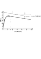
- FIG. 5 shows an example of charge / discharge efficiency characteristics of the entire power supply system according to the embodiment of the present invention shown in FIG.
- the solid line shows an example of the charge / discharge efficiency characteristics of the entire power supply system according to the embodiment of the present invention shown in FIG. 2, and the dotted line for comparison indicates all of the charge / discharge request values regardless of the value.
- An example of charge / discharge efficiency characteristics of the entire conventional general power supply system in which the charge / discharge request value is equally divided and assigned to each string is shown.
- the input / output power range R1 in which the power supply system according to the embodiment of the present invention shown in FIG. 2 can operate with high efficiency is the range of the conventional general power supply system. It is wider than the range R2 of input / output power that can be operated with high efficiency.
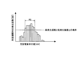
- FIG. 6 is a diagram showing a distribution example of charge / discharge request values in a certain facility.
- the power supply system according to the embodiment of the present invention shown in FIG. 2 When the power supply system according to the embodiment of the present invention shown in FIG. 2 is introduced into a certain facility, the power supply system according to the embodiment of the present invention shown in FIG. 2 can be operated with high efficiency.
- the scale of introduction of the power supply system according to the embodiment of the present invention shown in FIG. 2 (capacity of the storage battery) so that the output power range R1 includes the charge / discharge request value range R3 that is frequently generated in a certain facility. , The number of strings).
- the power supply system according to the embodiment of the present invention shown in FIG. 2 performs control such that the charge / discharge efficiency of the entire system is maximized in consideration of the charge / discharge efficiency of the string. is doing.
- the efficiency decreases in proportion to the magnitude of the input / output power (see FIG. 3), and the degradation is the magnitude of the input / output power. If the control is performed so that the charging / discharging efficiency of the entire system is maximized, there is a possibility that the storage battery is greatly deteriorated even if the efficiency is good.
- the control is not performed based on the input / output power (16 kW) at which the maximum efficiency of the string can be obtained in consideration of the charge / discharge efficiency of the string, but the maximum efficiency of the string Control may be performed such that the charge / discharge efficiency of the entire system is near the maximum with reference to the input / output power smaller than the input / output power (16 kW) obtained.
- the charge / discharge efficiency of the string is calculated by adding only the charge / discharge conversion efficiency of the PCS 2 to the charge / discharge efficiency of the storage battery 3, but the power supply system according to the present invention is limited to this.
- the charging / discharging efficiency of the storage battery 3 takes into account the power transmission efficiency between the PCS 2 and the storage battery 3 (efficiency based on the resistance of the power line between the PCS 2 and the storage battery 3) and the charging / discharging conversion efficiency of the PCS 2 to charge the string.
- the discharge efficiency may be calculated.
- the storage batteries 3A to 3E have all the same charge / discharge characteristics
- the PCS 2A to 2E have all the same charge / discharge efficiency characteristics.
- the present invention is not limited to this, and has a configuration including a plurality of storage batteries having different charge / discharge characteristics and / or a configuration including a plurality of power converters having different charge / discharge characteristics, and is required from the outside. Based on the charge / discharge request, the system may perform control so that the charge / discharge efficiency of the entire system is maximized or near the maximum.
Landscapes
- Engineering & Computer Science (AREA)
- Manufacturing & Machinery (AREA)
- Chemical & Material Sciences (AREA)
- Chemical Kinetics & Catalysis (AREA)
- Electrochemistry (AREA)
- General Chemical & Material Sciences (AREA)
- Power Engineering (AREA)
- Microelectronics & Electronic Packaging (AREA)
- Charge And Discharge Circuits For Batteries Or The Like (AREA)
- Supply And Distribution Of Alternating Current (AREA)
Abstract
L'invention concerne un système d'alimentation électrique qui comprend une pluralité de chaînes dans lesquelles une cellule de stockage et un dispositif de conversion électrique sont connectés en série, et qui comprend une unité de commande destinée à commander les dispositifs de conversion électrique des chaînes. Les chaînes sont connectées les unes aux autres de telle sorte que les cellules de stockage des chaînes sont connectées en parallèle. Sur la base d'une demande de chargement-déchargement issue de l'extérieur, l'unité de commande détermine la distribution d'électricité devant être attribuée à chacune de la pluralité de chaînes, de telle sorte que le rendement de chargement-déchargement du système dans son ensemble est à un maximum ou proche de son maximum, en tenant compte du rendement de chargement-déchargement des chaînes calculé par addition d'au moins le rendement de chargement-déchargement des dispositifs de conservation électrique au rendement de chargement-déchargement des cellules de stockage.
Applications Claiming Priority (2)
| Application Number | Priority Date | Filing Date | Title |
|---|---|---|---|
| JP2011-140805 | 2011-06-24 | ||
| JP2011140805 | 2011-06-24 |
Publications (1)
| Publication Number | Publication Date |
|---|---|
| WO2012176868A1 true WO2012176868A1 (fr) | 2012-12-27 |
Family
ID=47422696
Family Applications (1)
| Application Number | Title | Priority Date | Filing Date |
|---|---|---|---|
| PCT/JP2012/065962 Ceased WO2012176868A1 (fr) | 2011-06-24 | 2012-06-22 | Système d'alimentation électrique |
Country Status (1)
| Country | Link |
|---|---|
| WO (1) | WO2012176868A1 (fr) |
Cited By (12)
| Publication number | Priority date | Publication date | Assignee | Title |
|---|---|---|---|---|
| WO2014136705A1 (fr) * | 2013-03-04 | 2014-09-12 | 株式会社 東芝 | Système de cellule secondaire ayant une pluralité de cellules, et procédé de distribution d'énergie électrique de charge/décharge |
| JP2014183654A (ja) * | 2013-03-19 | 2014-09-29 | Honda Motor Co Ltd | 電力供給システム |
| WO2015198632A1 (fr) * | 2014-06-24 | 2015-12-30 | 株式会社 東芝 | Système de stockage d'énergie et procédé d'estimation de paramètres caractéristiques |
| JP2016167912A (ja) * | 2015-03-09 | 2016-09-15 | Fdk株式会社 | 蓄電システム |
| WO2018016546A1 (fr) * | 2016-07-20 | 2018-01-25 | ナブテスコ株式会社 | Dispositif de gestion d'énergie |
| JP2018023282A (ja) * | 2014-03-27 | 2018-02-08 | 京セラ株式会社 | 電力管理装置、電力管理システム及び電力管理方法 |
| EP3319199A4 (fr) * | 2015-06-30 | 2019-02-27 | Kabushiki Kaisha Toshiba | Système de gestion de batterie rechargeable |
| WO2019054231A1 (fr) * | 2017-09-12 | 2019-03-21 | 株式会社 東芝 | Dispositif et procédé de commande de batterie de stockage |
| CN110268547A (zh) * | 2017-04-21 | 2019-09-20 | 惠普发展公司,有限责任合伙企业 | 基于效率的电池配置 |
| JP2023018482A (ja) * | 2021-07-27 | 2023-02-08 | 横河電機株式会社 | コントローラ、制御プログラム、制御方法及び電力供給システム |
| WO2023203927A1 (fr) * | 2022-04-19 | 2023-10-26 | 矢崎総業株式会社 | Dispositif de commande de batterie de stockage, système de stockage d'énergie électrique, et procédé de commande de batterie de stockage |
| WO2024075450A1 (fr) * | 2022-10-04 | 2024-04-11 | 矢崎総業株式会社 | Dispositif de commande de batterie de stockage, système de stockage d'électricité et procédé de commande de batterie de stockage |
Citations (3)
| Publication number | Priority date | Publication date | Assignee | Title |
|---|---|---|---|---|
| JP2000116014A (ja) * | 1998-10-06 | 2000-04-21 | Hitachi Ltd | 電力貯蔵装置 |
| JP2002345161A (ja) * | 2001-05-11 | 2002-11-29 | Denso Corp | 複数電圧出力型車両用電源装置およびその制御方法 |
| JP2011101523A (ja) * | 2009-11-06 | 2011-05-19 | Panasonic Electric Works Co Ltd | 電力供給装置 |
-
2012
- 2012-06-22 WO PCT/JP2012/065962 patent/WO2012176868A1/fr not_active Ceased
Patent Citations (3)
| Publication number | Priority date | Publication date | Assignee | Title |
|---|---|---|---|---|
| JP2000116014A (ja) * | 1998-10-06 | 2000-04-21 | Hitachi Ltd | 電力貯蔵装置 |
| JP2002345161A (ja) * | 2001-05-11 | 2002-11-29 | Denso Corp | 複数電圧出力型車両用電源装置およびその制御方法 |
| JP2011101523A (ja) * | 2009-11-06 | 2011-05-19 | Panasonic Electric Works Co Ltd | 電力供給装置 |
Cited By (33)
| Publication number | Priority date | Publication date | Assignee | Title |
|---|---|---|---|---|
| KR101725701B1 (ko) * | 2013-03-04 | 2017-04-10 | 가부시끼가이샤 도시바 | 복수 전지를 갖는 이차 전지 시스템 및 충방전 전력 또는 전류의 배분 방법 |
| US9825474B2 (en) | 2013-03-04 | 2017-11-21 | Kabushiki Kaisha Toshiba | Secondary battery system with plural batteries and method of distributing charge/discharge power |
| KR20150106912A (ko) * | 2013-03-04 | 2015-09-22 | 가부시끼가이샤 도시바 | 복수 전지를 갖는 이차 전지 시스템 및 충방전 전력 등의 배분 방법 |
| CN105027379A (zh) * | 2013-03-04 | 2015-11-04 | 株式会社东芝 | 具有多个电池的二次电池系统及充放电功率等的分配方法 |
| WO2014136705A1 (fr) * | 2013-03-04 | 2014-09-12 | 株式会社 東芝 | Système de cellule secondaire ayant une pluralité de cellules, et procédé de distribution d'énergie électrique de charge/décharge |
| EP2966751A4 (fr) * | 2013-03-04 | 2016-08-17 | Toshiba Kk | Système de cellule secondaire ayant une pluralité de cellules, et procédé de distribution d'énergie électrique de charge/décharge |
| CN105027379B (zh) * | 2013-03-04 | 2018-05-25 | 株式会社东芝 | 具有多个电池的二次电池系统及充放电功率等的分配方法 |
| JP2014171335A (ja) * | 2013-03-04 | 2014-09-18 | Toshiba Corp | 複数電池を有する二次電池システム及び充放電電力等の配分方法 |
| JP2014183654A (ja) * | 2013-03-19 | 2014-09-29 | Honda Motor Co Ltd | 電力供給システム |
| JP2018023282A (ja) * | 2014-03-27 | 2018-02-08 | 京セラ株式会社 | 電力管理装置、電力管理システム及び電力管理方法 |
| JPWO2015198632A1 (ja) * | 2014-06-24 | 2017-04-20 | 株式会社東芝 | 蓄電システム及び特性パラメータの推定方法 |
| EP3163708A4 (fr) * | 2014-06-24 | 2018-01-24 | Kabushiki Kaisha Toshiba | Système de stockage d'énergie et procédé d'estimation de paramètres caractéristiques |
| WO2015198632A1 (fr) * | 2014-06-24 | 2015-12-30 | 株式会社 東芝 | Système de stockage d'énergie et procédé d'estimation de paramètres caractéristiques |
| US10261132B2 (en) | 2014-06-24 | 2019-04-16 | Kabushiki Kaisha Toshiba | Electricity storage system and method of estimating characteristic parameter |
| JP2016167912A (ja) * | 2015-03-09 | 2016-09-15 | Fdk株式会社 | 蓄電システム |
| EP3319199A4 (fr) * | 2015-06-30 | 2019-02-27 | Kabushiki Kaisha Toshiba | Système de gestion de batterie rechargeable |
| WO2018016546A1 (fr) * | 2016-07-20 | 2018-01-25 | ナブテスコ株式会社 | Dispositif de gestion d'énergie |
| JPWO2018016546A1 (ja) * | 2016-07-20 | 2019-04-11 | ナブテスコ株式会社 | エネルギ管理装置 |
| CN110268547B (zh) * | 2017-04-21 | 2022-08-26 | 惠普发展公司,有限责任合伙企业 | 基于效率的电池配置 |
| CN110268547A (zh) * | 2017-04-21 | 2019-09-20 | 惠普发展公司,有限责任合伙企业 | 基于效率的电池配置 |
| EP3613123A4 (fr) * | 2017-04-21 | 2020-10-07 | Hewlett-Packard Development Company, L.P. | Configurations de batterie fondées sur le rendement |
| US11264811B2 (en) | 2017-04-21 | 2022-03-01 | Hewlett-Packard Development Company, L.P. | Efficiency based battery configurations |
| JP2019054565A (ja) * | 2017-09-12 | 2019-04-04 | 株式会社東芝 | 蓄電池制御装置及びその方法 |
| JP7002894B2 (ja) | 2017-09-12 | 2022-01-20 | 株式会社東芝 | 蓄電池制御装置及びその方法 |
| WO2019054231A1 (fr) * | 2017-09-12 | 2019-03-21 | 株式会社 東芝 | Dispositif et procédé de commande de batterie de stockage |
| JP2023018482A (ja) * | 2021-07-27 | 2023-02-08 | 横河電機株式会社 | コントローラ、制御プログラム、制御方法及び電力供給システム |
| JP7588045B2 (ja) | 2021-07-27 | 2024-11-21 | 横河電機株式会社 | コントローラ、制御プログラム、制御方法及び電力供給システム |
| WO2023203927A1 (fr) * | 2022-04-19 | 2023-10-26 | 矢崎総業株式会社 | Dispositif de commande de batterie de stockage, système de stockage d'énergie électrique, et procédé de commande de batterie de stockage |
| JP2023158772A (ja) * | 2022-04-19 | 2023-10-31 | 矢崎総業株式会社 | 蓄電池制御装置、蓄電システム、及び蓄電池制御方法 |
| JP7534351B2 (ja) | 2022-04-19 | 2024-08-14 | 矢崎総業株式会社 | 蓄電池制御装置、蓄電システム、及び蓄電池制御方法 |
| WO2024075450A1 (fr) * | 2022-10-04 | 2024-04-11 | 矢崎総業株式会社 | Dispositif de commande de batterie de stockage, système de stockage d'électricité et procédé de commande de batterie de stockage |
| JP2024053666A (ja) * | 2022-10-04 | 2024-04-16 | 矢崎総業株式会社 | 蓄電池制御装置、蓄電システム、及び蓄電池制御方法 |
| JP7652746B2 (ja) | 2022-10-04 | 2025-03-27 | 矢崎総業株式会社 | 蓄電池制御装置、蓄電システム、及び蓄電池制御方法 |
Similar Documents
| Publication | Publication Date | Title |
|---|---|---|
| WO2012176868A1 (fr) | Système d'alimentation électrique | |
| US9948119B2 (en) | Control of parallel battery utilization | |
| EP4054051B1 (fr) | Système de stockage d'énergie et procédé de gestion de batterie | |
| JP5542781B2 (ja) | 蓄電池制御システム及び蓄電池制御方法 | |
| JP6238107B2 (ja) | 蓄電池の管理システム | |
| KR102400502B1 (ko) | 에너지 저장 시스템 | |
| CN103299506B (zh) | 电力控制装置、电力控制方法、程序、集成电路及蓄电池模组 | |
| JP5838313B2 (ja) | 蓄電池充放電制御装置および蓄電池充放電制御方法 | |
| US8946929B2 (en) | Method and apparatus for effective utilization of energy storage components within a microgid | |
| JP5704156B2 (ja) | 蓄電池システム | |
| US9054556B2 (en) | Power supply device and method of controlling the same | |
| JP5809934B2 (ja) | 蓄電装置及び電源システム | |
| JPWO2013038764A1 (ja) | 二次電池システム及び二次電池の運用方法 | |
| CN115986883A (zh) | 一种储能系统及其控制方法 | |
| KR20150135843A (ko) | 하이브리드 에너지 저장 시스템 및 그 제어 방법 | |
| JP2023030289A (ja) | バッテリーユニットの制御装置 | |
| JP7756511B2 (ja) | 蓄電システムの充放電制御方法 | |
| WO2012043133A1 (fr) | Dispositif de commande de charge/décharge de batterie rechargeable et procédé de commande de charge/décharge de batterie rechargeable | |
| WO2025238896A1 (fr) | Système de distribution de puissance en courant continu | |
| JP6580456B2 (ja) | 電力制御装置、電力管理システムおよび電力管理方法 | |
| JP2026005763A (ja) | 分散型電源システム | |
| KR20250085359A (ko) | 에너지 저장 시스템 및 그것의 동작 방법 | |
| JP2024154613A (ja) | 電源装置 | |
| JP6300568B2 (ja) | 電力供給システム | |
| JP6175902B2 (ja) | 電源供給システム、制御装置、電源供給方法、プログラム、及び記録媒体 |
Legal Events
| Date | Code | Title | Description |
|---|---|---|---|
| 121 | Ep: the epo has been informed by wipo that ep was designated in this application |
Ref document number: 12801842 Country of ref document: EP Kind code of ref document: A1 |
|
| NENP | Non-entry into the national phase |
Ref country code: DE |
|
| 122 | Ep: pct application non-entry in european phase |
Ref document number: 12801842 Country of ref document: EP Kind code of ref document: A1 |
|
| NENP | Non-entry into the national phase |
Ref country code: JP |