WO2012176880A1 - Panneau d'isolation sous vide - Google Patents
Panneau d'isolation sous vide Download PDFInfo
- Publication number
- WO2012176880A1 WO2012176880A1 PCT/JP2012/065997 JP2012065997W WO2012176880A1 WO 2012176880 A1 WO2012176880 A1 WO 2012176880A1 JP 2012065997 W JP2012065997 W JP 2012065997W WO 2012176880 A1 WO2012176880 A1 WO 2012176880A1
- Authority
- WO
- WIPO (PCT)
- Prior art keywords
- side plates
- vacuum heat
- heat insulation
- sealed space
- protrusion
- Prior art date
- Legal status (The legal status is an assumption and is not a legal conclusion. Google has not performed a legal analysis and makes no representation as to the accuracy of the status listed.)
- Ceased
Links
Images


Classifications
-
- F—MECHANICAL ENGINEERING; LIGHTING; HEATING; WEAPONS; BLASTING
- F25—REFRIGERATION OR COOLING; COMBINED HEATING AND REFRIGERATION SYSTEMS; HEAT PUMP SYSTEMS; MANUFACTURE OR STORAGE OF ICE; LIQUEFACTION SOLIDIFICATION OF GASES
- F25D—REFRIGERATORS; COLD ROOMS; ICE-BOXES; COOLING OR FREEZING APPARATUS NOT OTHERWISE PROVIDED FOR
- F25D23/00—General constructional features
- F25D23/06—Walls
- F25D23/065—Details
-
- F—MECHANICAL ENGINEERING; LIGHTING; HEATING; WEAPONS; BLASTING
- F25—REFRIGERATION OR COOLING; COMBINED HEATING AND REFRIGERATION SYSTEMS; HEAT PUMP SYSTEMS; MANUFACTURE OR STORAGE OF ICE; LIQUEFACTION SOLIDIFICATION OF GASES
- F25D—REFRIGERATORS; COLD ROOMS; ICE-BOXES; COOLING OR FREEZING APPARATUS NOT OTHERWISE PROVIDED FOR
- F25D2201/00—Insulation
- F25D2201/10—Insulation with respect to heat
- F25D2201/14—Insulation with respect to heat using subatmospheric pressure
Definitions
- the present invention relates to a vacuum heat insulation panel formed by evacuating the internal space of a hollow panel.
- Insulation panels are used for housings such as refrigerators and cold storage containers, and wall materials for air transport containers. 2. Description of the Related Art Conventionally, a heat insulating panel in which a heat insulating material such as urethane foam or polystyrene is embedded between a pair of side plates is known. However, when producing a heat insulating panel using these heat insulating materials, a very thick heat insulating material is required to obtain sufficient heat insulating properties.
- Such a heat insulation panel is called a vacuum heat insulation panel.
- the heat insulation can be improved as compared with the case where only the heat insulating material is used.
- the side plates are deformed due to the difference between the atmospheric pressure and the atmospheric pressure in the internal space, the side plates come into contact with each other, and heat may be directly conducted between the side plates. For this reason, it is desirable to provide the vacuum heat insulation panel with a reinforcing means for suppressing such deformation.
- Patent Document 1 has a drawback that the weight of the vacuum heat insulation panel is increased because a plurality of steel plates are used.
- the thickness of the vacuum heat insulation panel cannot be reduced sufficiently.
- a case where a shipping container is manufactured using such a vacuum heat insulating panel can be considered, but the outer dimensions of the shipping container are often defined in advance. For this reason, the larger the thickness of the vacuum heat insulation panel, the smaller the internal volume, and the load capacity decreases.
- An object of the present invention is to provide a vacuum heat insulation panel that is light in weight, small in thickness, and excellent in heat insulation performance.
- the vacuum heat insulation panel according to the present invention includes a sealed space formed by using a pair of side plates opposed to each other and four frame members arranged along each side of the side plates, and evacuating the sealed space. And an air pressure inside and outside of the sealed space by contacting an inner plate and an inner surface of at least one of the side plates disposed in the sealed space substantially parallel to the pair of side plates.
- the inner plate has a plurality of protrusions, and the protrusions are made of a material having a lower thermal conductivity than the inner plate. It is formed.
- the protrusions are arranged in a state of being inserted through through holes provided in the inner plate, and both end portions of the protrusions respectively contact the inner surfaces of the pair of side plates. It is desirable to touch.
- each of the protruding portions has a substantially conical shape at each tip portion that abuts on the side plate.
- the protrusion is formed of glass or ceramic.
- one or more through holes for weight reduction be provided on the side surface of the inner plate.
- the frame member is bent at an obtuse angle at the side portions sandwiching the central portion of the flat plate, and the end portions of the side portions are bent so as to be parallel to each other. It is desirable that the corresponding side plate is in surface contact and a projection provided on each side plate is brought into contact with the vicinity of the boundary between the central portion and each side portion.
- the inner plate is disposed substantially parallel to the pair of side plates, the plurality of protrusions having lower thermal conductivity than the inner plate are disposed on the inner plate, and these protrusions are brought into contact with the side plates.
- the deformation of the side plate due to the difference between the atmospheric pressure of the internal space and the atmospheric pressure is suppressed.
- the contact area of a projection part and a side plate can be made very small.
- FIG. 1A It is a notional top view which shows the whole structure of the vacuum heat insulation panel which concerns on Embodiment 1 of this invention. It is AA sectional drawing of FIG. 1A. It is a schematic sectional drawing which expands and shows the part shown by the code
- FIG. 3B is a sectional view taken along line BB in FIG. 3A. It is an external appearance perspective view which shows notionally the other example of the storage box produced using the vacuum heat insulation panel which concerns on Embodiment 1 of invention. It is a fragmentary sectional view of the storage box shown in FIG. 4A.
- Embodiment 1 of the Invention 1A and 1B are conceptual views showing the overall configuration of the vacuum heat insulation panel 100 according to the first embodiment, FIG. 1A is a plan view, and FIG. 1B is a cross-sectional view taken along line AA in FIG. 1A.
- the pair of side plates 101 and 102 are disposed so as to face each other.
- An inner plate 110 is arranged between the side plates 101 and 102.
- the frame members 103 to 106 are disposed along the sides of the side plates 101 and 102, and the side plates 101 and 102 and the frame members 103 to 106 are fixed in close contact with each other.
- a sealed space 120 is formed by the side plates 101 and 102 and the frame members 103 to 106.
- the sealed space 120 is evacuated to a high vacuum, for example, using the exhaust pipe 119.
- high vacuum refers to a high vacuum defined by JIS (Japanese Industrial Standards), that is, a state where the atmospheric pressure is 10 ⁇ 5 Pa to 10 ⁇ 1 Pa.
- JIS Japanese Industrial Standards
- the vacuum heat insulation panel 100 of this embodiment can be used even in a medium vacuum or a low vacuum.
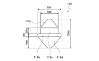
- FIG. 2A is an enlarged view of a portion indicated by reference numeral X in FIG. 1B
- FIG. 2B is a schematic side view of the protrusion shown in FIG. 1B.
- the side plates 101 and 102 for example, a metal plate such as stainless steel can be used.
- the JIS SUS304-H (spring material) is used.
- the dimension of the side plates 101 and 102 was set to 550 mm ⁇ 550 mm.
- the thickness of the side plates 101 and 102 is preferably 0.2 to 0.8 mm, for example, but here it is about 0.5 mm.
- the side plates 101 and 102 those in which the outer side surfaces 101a and 102a are mirror-finished can be used.
- the frame material 103 for example, a metal plate such as stainless steel can be used.
- the frame member 103 is formed by bending the side portions 103b and 103c sandwiching the central portion 103a at an obtuse angle and further bending the end portions 103d and 103e so as to be parallel to each other.
- the concave portions 101b and 102b of the side plates 101 and 102 are brought into contact with each other in the vicinity of the boundary between the central portion 103a and the side portions 103b and 103c.
- the total width W1 of the frame member 103 is, for example, 12 mm, and the length W2 of the contact portion with the side plates 101, 102 is, for example, 5 mm or less.
- the end portions 103 d and 103 e are in surface contact with the vicinity of the edge portions of the side plates 101 and 102.
- the inside of the sealed space 120 is set to a high vacuum, the vicinity of the central portion 103a is pressed from both sides by the concave portions 101b and 102b due to the pressure difference between the inside and outside of the sealed space 120. Thereby, even if the overall length of the frame member 103 is increased, sufficient strength can be obtained. Any other shape may be used as long as the path length of the heat conduction is longer than the distance between the side plates 101 and 102. Although only the frame member 103 is shown in FIG. 2A, the structures of the other frame members 104 to 106 are the same.
- the JIS SUS304-H is used as the metal material of the frame members 103 to 106, and the thickness of each of the frame members 103 to 106 is about 0.2 mm. Then, by fixing these frame members 103 to 106 by seam welding or the like, the frame 109 of the vacuum heat insulating panel 100 as shown by the dotted line in FIG. 1A was assembled. Further, seam welding was performed along each side of the side plates 101 and 102 to fix the frame members 103 to 106 and the side plates 101 and 102 in close contact with the welded portions 201 and 202. Seam welding is a type of resistance welding and is a method of continuously welding objects to be welded by rotating an electrode while applying pressure and energizing using a roller electrode.
- the inner plate 110 for example, a metal such as stainless steel can be used.
- the JIS SUS304-H is used as a material for forming the inner plate 110.
- the thickness of the inner plate 110 was about 0.2 mm.
- the inner plate 110 is disposed so as not to contact the frame members 103 to 106.
- the inner plate 110 is provided with a large number of through holes 111.
- the diameter of the through hole 111 is, for example, 6 mm.
- the protrusion 112 is inserted into the through hole 111.
- the protrusion 112 of the present embodiment includes a small-diameter columnar portion 112a (for example, 2 mm in height and 6 mm in diameter) and a large-diameter columnar portion 112b (for example, 1 mm in height and 8 mm in diameter). It is integrally formed so that one end surfaces may contact
- a small-diameter and substantially conical tip 112c (for example, 3 mm in height and 6 mm in diameter) is formed on the other end surface of the small-diameter cylindrical portion 112a, and a large-diameter and substantially conical on the other end surface of the large-diameter cylindrical portion 112c.
- 112d (for example, height 4mm, diameter 8mm) is integrally formed, respectively.
- these protrusions 112 are held by the inner plate 110 simply by inserting the small-diameter cylindrical portion 112a and the tip portion 112c into the through hole 111.
- one tip 112 c of the projection 112 abuts on the inner surface of the side plate 102 to support the side plate 102, and the other tip 112 d of the projection 112 is connected to the side plate 101.
- the side plate 101 is supported by contacting the inner side surface.
- tip portions 112c and 112d are substantially conical is to reduce the contact area between the projection 112 and the side plates 101 and 102, thereby suppressing heat conduction.
- the protrusion 112 is formed of a material having a lower thermal conductivity than that of the side plates 101 and 102 and the inner plate 110.
- the protrusion 112 is made of glass.
- the thermal conductivity of the JIS SUS304-H which is the material for forming the inner plate 110, is 18 W / mK (W is watts, m is meters, K is Kelvin), for example, whereas the thermal conductivity of glass is The rate is, for example, 0.7 W / mK.
- the protrusion 112 that can suppress deformation of the side plates 101 and 102 due to evacuation in the sealed space 120 and has extremely low thermal conductivity is formed at low cost. be able to.
- the protrusion 112 can be formed of a material other than glass.
- the load on the protrusion 112 is about 15 kg at the maximum (the same is true in the low vacuum, medium vacuum, and high vacuum of the JIS).
- ceramic has a thermal conductivity of about 0.6 W / mK and has a sufficiently high strength, and thus is suitable as the protrusion 112 of the present embodiment.
- the protrusion 112 is made of ceramic, there is an advantage that the protrusion 112 can be easily processed.
- the inner plate 110 is provided with a plurality of weight reduction through holes 113.
- the weight reduction through-hole 113 air flow can be facilitated when evacuating the sealed space 120.
- the size and number of the through holes 113 for weight reduction are arbitrary. However, in order to reduce the weight of the vacuum heat insulating panel 100, it is desirable to increase the total area of the weight reduction through-holes 113 within a range in which there is no problem in the strength of the inner plate 110.
- the diameter of the through hole 113 for weight reduction is 30 mm
- the pitch of the through hole 113 for weight reduction is 38 mm.
- the exhaust pipe 119 is used to evacuate the sealed space 120.
- the type of the exhaust pipe 119 and the like are not limited, but it is desirable to perform a process that can maintain the inside of the sealed space 120 in a vacuum state (for example, the high vacuum of JIS) for a long period of time.
- the exhaust pipe 119 has a double pipe structure, a stainless pipe having a diameter of about 10 mm and a length of about 1 mm is used as the outer pipe, and a copper pipe is used as the inner pipe.
- the exhaust pipe 119 was press-bonded after being evacuated, and the exhaust pipe 119 was pressure-bonded, and the outer end of the exhaust pipe 119 was welded. Thereby, the intrusion of atmospheric gas into the sealed space 120 can be prevented, and the sealed space 120 is maintained at, for example, the high vacuum of JIS.
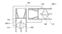
- FIG. 3A and 3B are examples in which a storage box is manufactured using the vacuum heat insulating panel 100 of the present embodiment
- FIG. 3A is an external perspective view
- FIG. 3B is a cross-sectional view along line BB in FIG. 3A.
- the storage box 300 has a substantially regular hexahedron shape, and is manufactured using six vacuum heat insulation panels 100. In FIG. 3A, only three vacuum heat insulation panels 100-1 to 100-3 are shown.
- the frame body 301 for example, a hard foam resin is used. As shown in FIG. 3B, the frame body 301 covers the ends of the two adjacent vacuum heat insulation panels 100 (the vacuum heat insulation panels 100-1 and 100-2 in FIG. 3B) and the vicinity thereof, These two vacuum heat insulation panels 100 are fixed so that the planes are at right angles. Thereby, each side of the six vacuum heat insulation panels 100 can be fixed to another adjacent vacuum heat insulation panel 100 to produce a substantially regular hexahedron containing box 300.
- the vacuum insulation panel 100-1 may be removed by pulling the frame 301 upward in FIG. 3B.
- FIG. 4A and FIG. 4B are other examples of the storage box created using the vacuum heat insulation panel 100 of this embodiment, FIG. 4A is an external perspective view, and FIG. 4B is a partial cross-sectional view.
- a box-shaped storage box body 401 having an upper opening 401a is formed by a single vacuum heat insulating panel.
- the side plates 402 and 403 and the inner plate 404 are each formed into a box shape by three-dimensional pressing.
- the protrusion 112 is loaded on the inner plate 404 and accommodated in the outer side plate 402, and further, the inner side plate 403 is accommodated in the inner plate 404.
- the upper opening 401a of the storage box body 401 can be closed by a lid (not shown).
- the lid one having the same configuration as the vacuum heat insulating panel 100 as shown in FIGS. 1A to 2B can be used.
- the inside of the sealed space 120 is set to, for example, a high vacuum (may be a medium vacuum or a low vacuum). For this reason, since heat conduction by the air convection in the sealed space 120 (heat conduction between the side plates 101 and 102) can be extremely reduced, sufficiently high heat insulation can be obtained.
- a high vacuum may be a medium vacuum or a low vacuum.
- the side plates 101 and 102 tend to be deformed inward by the negative pressure of the sealed space 120.
- a method for suppressing such deformation a method using a high-strength side plate or a method using an inner plate can be considered.
- a high-strength side plate is used in order to suppress this deformation, it is necessary to increase the thickness of the side plate, so that the total weight of the vacuum heat insulation panel 100 increases.
- the reinforcement means like the said patent document 1, since the weight of inner board itself is large, the total weight of the vacuum heat insulation panel 100 will become large.
- a plurality of through holes 111 are provided in the inner plate 110, the protruding portions 112 are inserted into the through holes 111, and both ends of the protruding portions 112 are connected to the side plates 101 and 102. It was supposed to be supported by contacting. For this reason, even if the inner plate 110 is formed very thin, the side plates 101 and 102 can be sufficiently reinforced. Therefore, according to the present embodiment, it is possible to obtain sufficient strength while reducing the weight of the vacuum heat insulating panel 100.
- the protrusion 112 is formed of glass or the like, which is a material having lower thermal conductivity than the side plates 101 and 102 and the inner plate 110. For this reason, it is difficult for heat to be conducted between the side plates 101 and 102 via the protrusion 112, and therefore, a very excellent heat insulating performance can be obtained.
- the frame members 103 to 106 have a bent structure as shown in FIG. 2A, so that the heat dissipation of these frame members 103 to 106 can be enhanced. Obtainable.
- the vacuum heat insulation panel 100 of the present embodiment makes the inside of the sealed space 120 in a vacuum state (high vacuum, medium vacuum, or low vacuum), and heat conduction through the protrusion 112 and the frame members 103 to 106. small. For this reason, even if the panel thickness is very thin, sufficiently high heat insulation performance can be obtained. That is, according to this embodiment, the vacuum heat insulation panel 100 with high heat insulation performance can be formed very thin.
- the panel thickness was 11 mm, and the thermal conductivity between the side plates 101 and 102 was 0.00030 W / mK.
- the thermal conductivity of the heat insulation panel using urethane foam is about 0.02 W / mK.
- the protrusion 112 is inserted into the through hole 111 of the inner plate 110 and both end portions of the protrusion 112 are brought into contact with the side plates 101, 102.
- the effects of the present invention can be obtained even with other structures.
- the vacuum heat insulating panel of the present invention can be used for heat insulating materials for various purposes such as transport containers, storage containers, refrigerators, freezers, vending machines, building wall materials, and heat shields for blast furnaces.
Landscapes
- Engineering & Computer Science (AREA)
- Chemical & Material Sciences (AREA)
- Combustion & Propulsion (AREA)
- Physics & Mathematics (AREA)
- Mechanical Engineering (AREA)
- Thermal Sciences (AREA)
- General Engineering & Computer Science (AREA)
- Thermal Insulation (AREA)
Abstract
L'invention porte sur un panneau d'isolation sous vide qui est léger, mince et présente d'excellentes propriétés d'isolation. Un espace étroitement étanche est formé par disposition d'une paire de panneaux latéraux de façon à être dirigés l'un vers l'autre et disposition de quatre éléments de cadre le long des divers côtés des panneaux latéraux. A l'aide d'un orifice d'échappement, l'espace étroitement étanche est évacué. Dans l'espace étroitement étanche, un panneau interne en acier inoxydable, etc. est disposé pour être sensiblement parallèle aux panneaux latéraux. De multiples saillies sont disposées sur le panneau interne. En résultat des saillies en contact avec la surface interne du panneau latéral avec les pointes de celui-ci, les panneaux latéraux sont supportés. Les saillies sont formées à partir d'un matériau avec une conductivité thermique inférieure à celle du panneau interne, tel que du verre ou de la céramique.
Applications Claiming Priority (2)
| Application Number | Priority Date | Filing Date | Title |
|---|---|---|---|
| JP2011140543A JP5890973B2 (ja) | 2011-06-24 | 2011-06-24 | 真空断熱パネル |
| JP2011-140543 | 2011-06-24 |
Publications (1)
| Publication Number | Publication Date |
|---|---|
| WO2012176880A1 true WO2012176880A1 (fr) | 2012-12-27 |
Family
ID=47422708
Family Applications (1)
| Application Number | Title | Priority Date | Filing Date |
|---|---|---|---|
| PCT/JP2012/065997 Ceased WO2012176880A1 (fr) | 2011-06-24 | 2012-06-22 | Panneau d'isolation sous vide |
Country Status (2)
| Country | Link |
|---|---|
| JP (1) | JP5890973B2 (fr) |
| WO (1) | WO2012176880A1 (fr) |
Cited By (26)
| Publication number | Priority date | Publication date | Assignee | Title |
|---|---|---|---|---|
| CN110998168A (zh) * | 2017-08-01 | 2020-04-10 | Lg电子株式会社 | 真空绝热体、制冷或加热设备、真空绝热体的制造方法 |
| CN111750604A (zh) * | 2015-08-03 | 2020-10-09 | Lg电子株式会社 | 冰箱、真空绝热体及其制造方法 |
| CN111854307A (zh) * | 2015-08-03 | 2020-10-30 | Lg电子株式会社 | 真空绝热体 |
| WO2021006640A1 (fr) | 2019-07-09 | 2021-01-14 | Lg Electronics Inc. | Module adiabatique à vide et réfrigérateur associé |
| EP3662193A4 (fr) * | 2017-08-01 | 2021-04-21 | LG Electronics Inc. | Corps adiabatique sous vide et réfrigérateur |
| US10995488B1 (en) | 2019-11-20 | 2021-05-04 | Whirlpool Corporation | Servicing assembly for an insulated structure |
| CN113074510A (zh) * | 2020-01-06 | 2021-07-06 | 青岛海尔电冰箱有限公司 | 真空绝热体及冰箱 |
| US11260727B2 (en) | 2017-08-01 | 2022-03-01 | Lg Electronics Inc. | Vehicle, refrigerator for vehicle, and controlling method for refrigerator for vehicle |
| US11274785B2 (en) | 2015-08-03 | 2022-03-15 | Lg Electronics Inc. | Vacuum adiabatic body and refrigerator |
| US11365931B2 (en) | 2015-08-04 | 2022-06-21 | Lg Electronics Inc. | Vacuum adiabatic body and refrigerator |
| US11466925B2 (en) | 2017-08-16 | 2022-10-11 | Lg Electronics Inc. | Vacuum adiabatic body and refrigerator |
| US11573048B2 (en) | 2015-08-03 | 2023-02-07 | Lg Electronics Inc. | Vacuum adiabatic body and refrigerator |
| US20230038053A1 (en) * | 2020-01-06 | 2023-02-09 | Qingdao Haier Refrigerator Co., Ltd. | Vacuum adiabatic body and refrigerator |
| US11585591B2 (en) | 2015-08-03 | 2023-02-21 | Lg Electronics Inc. | Vacuum adiabatic body and refrigerator |
| US11592230B2 (en) | 2015-08-03 | 2023-02-28 | Lg Electronics Inc. | Vacuum adiabatic body and refrigerator |
| US11598573B2 (en) | 2015-08-03 | 2023-03-07 | Lg Electronics Inc. | Vacuum adiabatic body and refrigerator |
| US11624550B2 (en) | 2017-08-01 | 2023-04-11 | Lg Electronics Inc. | Vacuum adiabatic body and refrigerator |
| US11774167B2 (en) | 2017-08-01 | 2023-10-03 | Lg Electronics Inc. | Vacuum adiabatic body and refrigerator |
| US11796246B2 (en) | 2015-08-03 | 2023-10-24 | Lg Electronics Inc. | Vacuum adiabatic body, fabrication method for the vacuum adiabatic body, porous substance package, and refrigerator |
| US11920858B2 (en) | 2015-08-03 | 2024-03-05 | Lg Electronics Inc. | Vacuum adiabatic body and refrigerator |
| US11920723B2 (en) | 2015-08-03 | 2024-03-05 | Lg Electronics Inc. | Vacuum adiabatic body and refrigerator |
| US11927386B2 (en) | 2015-08-03 | 2024-03-12 | Lg Electronics Inc. | Vacuum adiabatic body and refrigerator |
| WO2024133784A1 (fr) * | 2022-12-21 | 2024-06-27 | Softbox Systems Limited | Conteneur de transport thermiquement isolant et panneaux associés |
| US12078409B2 (en) | 2015-08-03 | 2024-09-03 | Lg Electronics Inc. | Vacuum adiabatic body and refrigerator |
| US12264872B2 (en) | 2022-10-24 | 2025-04-01 | Whirlpool Corporation | Insulation panel assembly for a refrigeration unit |
| US12385686B2 (en) | 2015-08-03 | 2025-08-12 | Lg Electronics Inc. | Vacuum adiabatic body and refrigerator |
Families Citing this family (6)
| Publication number | Priority date | Publication date | Assignee | Title |
|---|---|---|---|---|
| KR102205476B1 (ko) * | 2014-03-13 | 2021-01-20 | 삼성전자주식회사 | 진공단열재 및 이를 포함하는 냉장고 |
| JP2015187468A (ja) * | 2014-03-27 | 2015-10-29 | 株式会社松田技術研究所 | 真空断熱パイプ |
| JP2022513172A (ja) * | 2018-11-30 | 2022-02-07 | コンセプト グループ エルエルシー | 継手構造 |
| KR20220059319A (ko) * | 2020-11-02 | 2022-05-10 | 엘지전자 주식회사 | 진공단열체 및 진공단열체의 제조방법 |
| KR20220059333A (ko) * | 2020-11-02 | 2022-05-10 | 엘지전자 주식회사 | 진공단열체 및 냉장고 |
| KR20230038046A (ko) * | 2021-09-10 | 2023-03-17 | 삼성전자주식회사 | 냉장고 |
Citations (4)
| Publication number | Priority date | Publication date | Assignee | Title |
|---|---|---|---|---|
| JPH05509381A (ja) * | 1990-06-12 | 1993-12-22 | ベンソン デービット ケイ. | 改良されたコンパクトな真空断熱材 |
| JP2002071088A (ja) * | 2000-08-28 | 2002-03-08 | Matsuda Gijutsu Kenkyusho:Kk | 断熱パネル |
| JP2003042388A (ja) * | 2001-07-27 | 2003-02-13 | Matsuda Gijutsu Kenkyusho:Kk | 断熱パネル及びそれを用いたコンテナ |
| JP2003147872A (ja) * | 2001-11-12 | 2003-05-21 | Matsuda Gijutsu Kenkyusho:Kk | 金属製高真空断熱パネル |
Family Cites Families (1)
| Publication number | Priority date | Publication date | Assignee | Title |
|---|---|---|---|---|
| JP2005114028A (ja) * | 2003-10-07 | 2005-04-28 | Mimatsu Gyoumuten:Kk | 真空パネル・断熱材積層断熱プレート |
-
2011
- 2011-06-24 JP JP2011140543A patent/JP5890973B2/ja active Active
-
2012
- 2012-06-22 WO PCT/JP2012/065997 patent/WO2012176880A1/fr not_active Ceased
Patent Citations (4)
| Publication number | Priority date | Publication date | Assignee | Title |
|---|---|---|---|---|
| JPH05509381A (ja) * | 1990-06-12 | 1993-12-22 | ベンソン デービット ケイ. | 改良されたコンパクトな真空断熱材 |
| JP2002071088A (ja) * | 2000-08-28 | 2002-03-08 | Matsuda Gijutsu Kenkyusho:Kk | 断熱パネル |
| JP2003042388A (ja) * | 2001-07-27 | 2003-02-13 | Matsuda Gijutsu Kenkyusho:Kk | 断熱パネル及びそれを用いたコンテナ |
| JP2003147872A (ja) * | 2001-11-12 | 2003-05-21 | Matsuda Gijutsu Kenkyusho:Kk | 金属製高真空断熱パネル |
Cited By (57)
| Publication number | Priority date | Publication date | Assignee | Title |
|---|---|---|---|---|
| US12379151B2 (en) | 2015-08-03 | 2025-08-05 | Lg Electronics Inc. | Vacuum adiabatic body and refrigerator |
| US11920723B2 (en) | 2015-08-03 | 2024-03-05 | Lg Electronics Inc. | Vacuum adiabatic body and refrigerator |
| CN111854307A (zh) * | 2015-08-03 | 2020-10-30 | Lg电子株式会社 | 真空绝热体 |
| US12535263B2 (en) | 2015-08-03 | 2026-01-27 | Lg Electronics Inc. | Vacuum adiabatic body and refrigerator |
| US12504218B2 (en) | 2015-08-03 | 2025-12-23 | Lg Electronics Inc. | Vacuum adiabatic body and refrigerator |
| US12467683B2 (en) | 2015-08-03 | 2025-11-11 | Lg Electronics Inc. | Vacuum adiabatic body and refrigerator |
| US12392545B2 (en) | 2015-08-03 | 2025-08-19 | Lg Electronics Inc. | Vacuum adiabatic body and refrigerator |
| US12385685B2 (en) | 2015-08-03 | 2025-08-12 | Lg Electronics Inc. | Vacuum adiabatic body and refrigerator |
| US11137201B2 (en) | 2015-08-03 | 2021-10-05 | Lg Electronics Inc. | Vacuum adiabatic body and refrigerator |
| US12385686B2 (en) | 2015-08-03 | 2025-08-12 | Lg Electronics Inc. | Vacuum adiabatic body and refrigerator |
| US11274785B2 (en) | 2015-08-03 | 2022-03-15 | Lg Electronics Inc. | Vacuum adiabatic body and refrigerator |
| US11920857B2 (en) | 2015-08-03 | 2024-03-05 | Lg Electronics Inc. | Vacuum adiabatic body and refrigerator |
| CN111750604A (zh) * | 2015-08-03 | 2020-10-09 | Lg电子株式会社 | 冰箱、真空绝热体及其制造方法 |
| US11796246B2 (en) | 2015-08-03 | 2023-10-24 | Lg Electronics Inc. | Vacuum adiabatic body, fabrication method for the vacuum adiabatic body, porous substance package, and refrigerator |
| US11920858B2 (en) | 2015-08-03 | 2024-03-05 | Lg Electronics Inc. | Vacuum adiabatic body and refrigerator |
| US12146702B2 (en) | 2015-08-03 | 2024-11-19 | Lg Electronics Inc. | Vacuum adiabatic body and refrigerator |
| CN111854307B (zh) * | 2015-08-03 | 2023-01-24 | Lg电子株式会社 | 真空绝热体 |
| US11573048B2 (en) | 2015-08-03 | 2023-02-07 | Lg Electronics Inc. | Vacuum adiabatic body and refrigerator |
| US12078409B2 (en) | 2015-08-03 | 2024-09-03 | Lg Electronics Inc. | Vacuum adiabatic body and refrigerator |
| US11585591B2 (en) | 2015-08-03 | 2023-02-21 | Lg Electronics Inc. | Vacuum adiabatic body and refrigerator |
| US11592230B2 (en) | 2015-08-03 | 2023-02-28 | Lg Electronics Inc. | Vacuum adiabatic body and refrigerator |
| US11598573B2 (en) | 2015-08-03 | 2023-03-07 | Lg Electronics Inc. | Vacuum adiabatic body and refrigerator |
| US12050046B2 (en) | 2015-08-03 | 2024-07-30 | Lg Electronics Inc. | Vacuum adiabatic body and refrigerator |
| US11927386B2 (en) | 2015-08-03 | 2024-03-12 | Lg Electronics Inc. | Vacuum adiabatic body and refrigerator |
| US12320464B2 (en) | 2015-08-03 | 2025-06-03 | Lg Electronics Inc. | Vacuum adiabatic body and refrigerator |
| US11365931B2 (en) | 2015-08-04 | 2022-06-21 | Lg Electronics Inc. | Vacuum adiabatic body and refrigerator |
| US12281840B2 (en) | 2015-08-04 | 2025-04-22 | Lg Electronics Inc. | Vacuum adiabatic body and refrigerator |
| EP4491985A3 (fr) * | 2017-08-01 | 2025-03-19 | LG Electronics Inc. | Corps adiabatique sous vide et réfrigérateur |
| US11536415B2 (en) | 2017-08-01 | 2022-12-27 | Lg Electronics Inc. | Vacuum adiabatic body and refrigerator |
| US11807075B2 (en) | 2017-08-01 | 2023-11-07 | Lg Electronics Inc. | Vehicle, refrigerator for vehicle, and controlling method for refrigerator for vehicle |
| EP3662193A4 (fr) * | 2017-08-01 | 2021-04-21 | LG Electronics Inc. | Corps adiabatique sous vide et réfrigérateur |
| US11774167B2 (en) | 2017-08-01 | 2023-10-03 | Lg Electronics Inc. | Vacuum adiabatic body and refrigerator |
| US11725768B2 (en) | 2017-08-01 | 2023-08-15 | Lg Electronics Inc. | Vacuum adiabatic body, refrigerating or warming apparatus, and method for manufacturing vacuum adiabatic body |
| EP3662192A4 (fr) * | 2017-08-01 | 2021-04-28 | LG Electronics Inc. | Corps adiabatique sous vide, appareil de réfrigération ou de chauffage, procédé de fabrication du corps adiabatique sous vide |
| US11260727B2 (en) | 2017-08-01 | 2022-03-01 | Lg Electronics Inc. | Vehicle, refrigerator for vehicle, and controlling method for refrigerator for vehicle |
| US12372297B2 (en) | 2017-08-01 | 2025-07-29 | Lg Electronics Inc. | Vacuum adiabatic body and refrigerator |
| US11624550B2 (en) | 2017-08-01 | 2023-04-11 | Lg Electronics Inc. | Vacuum adiabatic body and refrigerator |
| US12339058B2 (en) | 2017-08-01 | 2025-06-24 | Lg Electronics Inc. | Vacuum adiabatic body and refrigerator |
| US12320463B2 (en) | 2017-08-01 | 2025-06-03 | Lg Electronics Inc. | Vacuum adiabatic body and refrigerator |
| CN110998168A (zh) * | 2017-08-01 | 2020-04-10 | Lg电子株式会社 | 真空绝热体、制冷或加热设备、真空绝热体的制造方法 |
| US12140262B2 (en) | 2017-08-01 | 2024-11-12 | Lg Electronics Inc. | Vacuum adiabatic body, refrigerating or warming apparatus, and method for manufacturing vacuum adiabatic body |
| US12209795B2 (en) | 2017-08-16 | 2025-01-28 | Lg Electronics Inc. | Vacuum adiabatic body and refrigerator |
| US11466925B2 (en) | 2017-08-16 | 2022-10-11 | Lg Electronics Inc. | Vacuum adiabatic body and refrigerator |
| US11781802B2 (en) | 2017-08-16 | 2023-10-10 | Lg Electronics Inc. | Vacuum adiabatic body and refrigerator |
| US12130073B2 (en) * | 2019-07-09 | 2024-10-29 | Lg Electronics Inc. | Vacuum adiabatic module and refrigerator |
| WO2021006640A1 (fr) | 2019-07-09 | 2021-01-14 | Lg Electronics Inc. | Module adiabatique à vide et réfrigérateur associé |
| EP3997402A4 (fr) * | 2019-07-09 | 2023-07-12 | LG Electronics Inc. | Module adiabatique à vide et réfrigérateur associé |
| US20220235997A1 (en) * | 2019-07-09 | 2022-07-28 | Lg Electronics Inc. | Vacuum adiabatic module and refrigerator |
| US10995488B1 (en) | 2019-11-20 | 2021-05-04 | Whirlpool Corporation | Servicing assembly for an insulated structure |
| US11427998B2 (en) | 2019-11-20 | 2022-08-30 | Whirlpool Corporation | Servicing assembly for an insulated structure |
| US11788280B2 (en) | 2019-11-20 | 2023-10-17 | Whirlpool Corporation | Servicing assembly for an insulated structure |
| US20230038053A1 (en) * | 2020-01-06 | 2023-02-09 | Qingdao Haier Refrigerator Co., Ltd. | Vacuum adiabatic body and refrigerator |
| CN113074510A (zh) * | 2020-01-06 | 2021-07-06 | 青岛海尔电冰箱有限公司 | 真空绝热体及冰箱 |
| US12130071B2 (en) * | 2020-01-06 | 2024-10-29 | Qingdao Haier Refrigerator Co., Ltd. | Vacuum adiabatic body and refrigerator |
| US12264872B2 (en) | 2022-10-24 | 2025-04-01 | Whirlpool Corporation | Insulation panel assembly for a refrigeration unit |
| WO2024133784A1 (fr) * | 2022-12-21 | 2024-06-27 | Softbox Systems Limited | Conteneur de transport thermiquement isolant et panneaux associés |
| GB2626127A (en) * | 2022-12-21 | 2024-07-17 | Softbox Systems Ltd | Thermally insulating transport container and panels therefor |
Also Published As
| Publication number | Publication date |
|---|---|
| JP2013007439A (ja) | 2013-01-10 |
| JP5890973B2 (ja) | 2016-03-22 |
Similar Documents
| Publication | Publication Date | Title |
|---|---|---|
| JP5890973B2 (ja) | 真空断熱パネル | |
| JP6083939B2 (ja) | 真空断熱パネルおよび断熱箱体 | |
| JP2012207682A (ja) | 真空断熱パネル | |
| JP2012021615A (ja) | 真空断熱パネル及びこれを用いた輸送用コンテナ | |
| CN1165731C (zh) | 隔热壁 | |
| KR102529853B1 (ko) | 진공단열체, 진공단열체의 제조방법, 다공성물질패키지, 및 냉장고 | |
| CN113945054A (zh) | 真空绝热体及真空绝热体的制造方法 | |
| JP2005214372A (ja) | 密閉断熱構造体及び断熱壁面間補強方法 | |
| CN103384627A (zh) | 气罐顶盖凸缘部的结构 | |
| CN105352252A (zh) | 隔绝外壳和用于制造该隔绝外壳的方法 | |
| KR20150112434A (ko) | 진공단열패널 | |
| US9687089B2 (en) | Insulated foam panels for refrigerated display cases | |
| JP2005163848A (ja) | 真空断熱材の製造方法及び断熱容体の製造方法 | |
| JP2003147872A (ja) | 金属製高真空断熱パネル | |
| JP6446773B2 (ja) | 低温タンク | |
| JP5969359B2 (ja) | 真空断熱パネルの製造方法 | |
| JP2017110813A (ja) | 真空断熱パネルおよび断熱箱体 | |
| US20190137167A1 (en) | Machine compartment for a vacuum insulated structure | |
| JP2013015168A (ja) | 真空断熱パネル | |
| JP2005127433A (ja) | 真空断熱パネル | |
| JPWO2016098840A1 (ja) | 複層ガラス | |
| JP2012215293A (ja) | 真空断熱構造体 | |
| WO2005057077A1 (fr) | Panneau d'isolation thermique, et structure d'isolation thermique faisant appel audit panneau | |
| KR20220059359A (ko) | 진공단열체 및 진공단열체의 제조방법 | |
| CN220354841U (zh) | 一种用于真空设备的隔热保温装置 |
Legal Events
| Date | Code | Title | Description |
|---|---|---|---|
| 121 | Ep: the epo has been informed by wipo that ep was designated in this application |
Ref document number: 12803174 Country of ref document: EP Kind code of ref document: A1 |
|
| NENP | Non-entry into the national phase |
Ref country code: DE |
|
| 122 | Ep: pct application non-entry in european phase |
Ref document number: 12803174 Country of ref document: EP Kind code of ref document: A1 |