WO2012177015A2 - 영상 부호화/복호화 방법 및 그 장치 - Google Patents
영상 부호화/복호화 방법 및 그 장치 Download PDFInfo
- Publication number
- WO2012177015A2 WO2012177015A2 PCT/KR2012/004694 KR2012004694W WO2012177015A2 WO 2012177015 A2 WO2012177015 A2 WO 2012177015A2 KR 2012004694 W KR2012004694 W KR 2012004694W WO 2012177015 A2 WO2012177015 A2 WO 2012177015A2
- Authority
- WO
- WIPO (PCT)
- Prior art keywords
- pixel
- filter
- depth
- picture
- filtering
- Prior art date
- Legal status (The legal status is an assumption and is not a legal conclusion. Google has not performed a legal analysis and makes no representation as to the accuracy of the status listed.)
- Ceased
Links
Images


Classifications
-
- H—ELECTRICITY
- H04—ELECTRIC COMMUNICATION TECHNIQUE
- H04N—PICTORIAL COMMUNICATION, e.g. TELEVISION
- H04N19/00—Methods or arrangements for coding, decoding, compressing or decompressing digital video signals
- H04N19/50—Methods or arrangements for coding, decoding, compressing or decompressing digital video signals using predictive coding
- H04N19/59—Methods or arrangements for coding, decoding, compressing or decompressing digital video signals using predictive coding involving spatial sub-sampling or interpolation, e.g. alteration of picture size or resolution
-
- H—ELECTRICITY
- H04—ELECTRIC COMMUNICATION TECHNIQUE
- H04N—PICTORIAL COMMUNICATION, e.g. TELEVISION
- H04N19/00—Methods or arrangements for coding, decoding, compressing or decompressing digital video signals
- H04N19/10—Methods or arrangements for coding, decoding, compressing or decompressing digital video signals using adaptive coding
- H04N19/102—Methods or arrangements for coding, decoding, compressing or decompressing digital video signals using adaptive coding characterised by the element, parameter or selection affected or controlled by the adaptive coding
- H04N19/117—Filters, e.g. for pre-processing or post-processing
-
- H—ELECTRICITY
- H04—ELECTRIC COMMUNICATION TECHNIQUE
- H04N—PICTORIAL COMMUNICATION, e.g. TELEVISION
- H04N19/00—Methods or arrangements for coding, decoding, compressing or decompressing digital video signals
- H04N19/50—Methods or arrangements for coding, decoding, compressing or decompressing digital video signals using predictive coding
- H04N19/597—Methods or arrangements for coding, decoding, compressing or decompressing digital video signals using predictive coding specially adapted for multi-view video sequence encoding
-
- H—ELECTRICITY
- H04—ELECTRIC COMMUNICATION TECHNIQUE
- H04N—PICTORIAL COMMUNICATION, e.g. TELEVISION
- H04N13/00—Stereoscopic video systems; Multi-view video systems; Details thereof
- H04N13/10—Processing, recording or transmission of stereoscopic or multi-view image signals
- H04N13/106—Processing image signals
- H04N13/161—Encoding, multiplexing or demultiplexing different image signal components
-
- H—ELECTRICITY
- H04—ELECTRIC COMMUNICATION TECHNIQUE
- H04N—PICTORIAL COMMUNICATION, e.g. TELEVISION
- H04N19/00—Methods or arrangements for coding, decoding, compressing or decompressing digital video signals
- H04N19/60—Methods or arrangements for coding, decoding, compressing or decompressing digital video signals using transform coding
- H04N19/625—Methods or arrangements for coding, decoding, compressing or decompressing digital video signals using transform coding using discrete cosine transform [DCT]
Definitions
- the present invention relates to image processing, and more particularly, to a resolution reduction update method and apparatus thereof.
- the 3D video may provide a realism and immersion by using a plurality of view channels, and the 3D video providing the stereoscopic effect may include a binocular 3D video, a multiview 3D video, a hologram, and the like.
- a texture video unlike a conventional 2D video, not only a texture video but also a depth video may be encoded and / or decoded together.
- a depth image may include depth information of objects in a screen.
- the three-dimensional effect can be represented by the above-described depth information.
- An object of the present invention is to provide an image encoding method and apparatus capable of improving image encoding efficiency and reducing complexity.
- Another object of the present invention is to provide an image decoding method and apparatus capable of improving image encoding efficiency and reducing complexity.
- Another technical problem of the present invention is to provide a resolution reduction update method and apparatus capable of improving image encoding efficiency and reducing complexity.
- Another technical problem of the present invention is to provide a filtering method and apparatus for improving image encoding efficiency.
- An embodiment of the present invention is a video decoding method.
- the method includes receiving a bitstream, generating a prediction block and a residual block for a current picture based on the bitstream, and reduced-resolution update (RRU) type information derived from the bitstream.
- RRU reduced-resolution update
- Performing up-sampling on the residual block generating a reconstruction block based on the prediction block and the residual block on which the upsampling is performed, and based on the RRU type information
- the RRU type information includes sampling ratio information and filter type information. Upsampling is performed based on a sampling rate indicated, and the filter indicated by the filter type information is performed in the filtering step. Based filtering to perform.
- the sampling rate information may indicate a higher sampling rate as the frequency of the region corresponding to the residual block is lower in the current block.
- the method of claim 1, wherein the performing of the filtering comprises: determining a window of a predetermined size and shape for a pixel to be filtered in the residual block and for the pixel to be filtered based on the pixels in the window.
- the method may further include performing filtering.
- the filter indicated by the filter type information is a bi-laterally weighted filter that performs weighted averaging based on pixels in the window. filter).
- the bidirectional weight filter performs weak smoothing when the pixel to be filtered is a pixel in an edge region including an edge, and the pixel to be filtered is configured to perform edge smoothing. Strong smoothing may be performed in the case of a pixel in a non-edge region that does not include.
- the filtering may be performed based on texture pixels in an area corresponding to the window in the texture picture.
- the filter indicated by the filter type information may be a bi-laterally weighted Winner_Take_All filter
- the bidirectional weighted WTA filter is a depth pixel in the window based on the texture pixel.
- a weighting score may be derived for each, and a pixel value of a depth pixel having the highest weight score among the depth pixels may be determined as an output value for the pixel to be filtered, wherein the depth pixel is within the depth picture. It may be a pixel.
- the filter indicated by the filter type information may be a bi-laterally weighted median filter
- the bidirectional weighted median filter may include a depth in the window based on the texture pixel.
- a weighting score is derived for each pixel
- a median value is derived among the depth pixels based on the weight score
- a pixel value of a depth pixel corresponding to the derived median value is obtained for the filtering target pixel.
- the depth pixel may be a pixel in the depth picture.
- the filter indicated by the filter type information is And a bidirectional weighted median filter, wherein the bidirectional weighted median filter derives a weighting score for each of the depth pixels based on depth pixels in the window, and based on the weight score
- the intermediate value may be derived from the pixels, and the pixel value of the depth pixel corresponding to the derived intermediate value may be determined as an output value for the filtering target pixel, and the depth pixel may be a pixel in the depth picture.
- the bidirectional weighted median filter performs weak smoothing when the pixel to be filtered is a pixel in an edge region including an edge, and the pixel to be filtered does not include an edge. In the case of non-edge pixels, strong smoothing may be performed.
- the apparatus includes: a receiver for receiving a bitstream, a prediction block and a residual block generator for generating a prediction block and a residual block for a current picture based on the bitstream, and an RRU derived from the bitstream
- a reconstruction block for generating a reconstruction block based on the up-sampler for performing up-sampling on the residual block, the prediction block, and the residual block on which the up-sampling is performed, based on -Resolution Update) type information
- a filter unit configured to perform filtering on the reconstruction block based on a generation unit and the RRU type information, wherein the RRU type information includes sampling ratio information and filter type information;
- the upsampler performs upsampling based on the sampling rate indicated by the sampling rate information, and the filter unit performs the filter type information. Performs filtering based on the filter indicated by.
- the sampling rate information may indicate a higher sampling rate as the frequency of the region corresponding to the residual block is lower in the current block.
- the filter unit is configured to determine a window having a predetermined size and shape with respect to the filtering target pixel in the residual block and perform filtering on the filtering target pixel based on the pixel in the window. Can be.
- the filter indicated by the filter type information is a bi-laterally weighted filter that performs weighted averaging based on pixels in the window. filter).
- the bidirectional weighting filter performs weak smoothing when the pixel to be filtered is a pixel in an edge region including an edge, and the pixel to be filtered is configured to perform edge smoothing. Strong smoothing may be performed in the case of a pixel in a non-edge region that does not include.
- the filter unit may perform filtering based on texture pixels in an area corresponding to the window in the texture picture.
- the filter indicated by the filter type information may be a bi-laterally weighted Winner_Take_All filter, wherein the bidirectional weighted WTA filter is a depth pixel in the window based on the texture pixel.
- a weighting score may be derived for each, and a pixel value of a depth pixel having the highest weight score among the depth pixels may be determined as an output value for the pixel to be filtered, wherein the depth pixel is within the depth picture. It may be a pixel.
- the filter indicated by the filter type information may be a bi-laterally weighted median filter, and the bidirectional weighted median filter is configured to determine a depth in the window based on the texture pixel.
- a weighting score is derived for each pixel, a median value is derived among the depth pixels based on the weight score, and a pixel value of a depth pixel corresponding to the derived median value is obtained for the filtering target pixel.
- the depth pixel may be a pixel in the depth picture.
- the filter indicated by the filter type information is And a bidirectional weighted median filter, wherein the bidirectional weighted median filter derives a weighting score for each of the depth pixels based on depth pixels in the window, and based on the weight score
- the intermediate value may be derived from the pixels, and the pixel value of the depth pixel corresponding to the derived intermediate value may be determined as an output value for the filtering target pixel, and the depth pixel may be a pixel in the depth picture.
- image encoding efficiency may be improved and complexity may be reduced.
- image decoding efficiency may be improved and complexity may be reduced.
- image encoding efficiency may be improved and complexity may be reduced.
- image encoding efficiency may be improved.
- FIG. 1 is a block diagram schematically illustrating an image encoding apparatus according to an embodiment of the present invention.
- FIG. 2 is a block diagram schematically illustrating an image decoding apparatus according to an embodiment of the present invention.
- FIG. 3 is a block diagram schematically illustrating an image encoding apparatus according to another embodiment of the present invention.
- FIG. 4 is a block diagram schematically illustrating an image decoding apparatus according to another embodiment of the present invention.
- FIG. 5 is a diagram illustrating an upsampling process and a filtering process according to the present invention.
- FIG. 6 is a flowchart schematically showing an embodiment of a decoding method according to the present invention.
- FIG. 7 is a flowchart schematically showing another embodiment of a decoding method according to the present invention.
- each of the components in the drawings described in the present invention are shown independently for the convenience of the description of the different characteristic functions in the image encoding / decoding apparatus, each component is implemented by separate hardware or separate software It does not mean to be.
- two or more of each configuration may be combined to form one configuration, or one configuration may be divided into a plurality of configurations.
- Embodiments in which each configuration is integrated and / or separated are also included in the scope of the present invention without departing from the spirit of the present invention.
- the components may not be essential components for performing essential functions in the present invention, but may be optional components for improving performance.
- the present invention can be implemented including only the components essential for implementing the essentials of the present invention except for the components used for improving performance, and the structure including only the essential components except for the optional components used for improving performance. Also included within the scope of the present invention.
- FIG. 1 is a block diagram schematically illustrating an image encoding apparatus according to an embodiment of the present invention.
- the image encoding apparatus may be applied to both a texture video and a depth video.
- the apparatus for encoding an image may include a motion estimator (ME) 110, a motion compensator (MC) 120, a down-sampler 130, and a converter ( Transformer (T) 135, Quantizer (Q) 140, Entropy coder 150, Inverse Quantizer or Dequantizer (IQ) 155, Inverse Transformer : IT) 160, an up-sampler 170, a filter unit 180, and a reference picture buffer 190.
- ME motion estimator
- MC motion compensator
- T Transformer
- Q Quantizer
- IQ Inverse Quantizer or Dequantizer
- IT Inverse Transformer : IT
- the picture may be divided into at least one processing unit.
- the processing unit may be a macro block, a prediction unit (PU), a transform unit (TU), or a coding unit (CU).
- PU prediction unit
- TU transform unit
- CU coding unit
- embodiments to be described below are described based on a processing unit generated by dividing a picture to be encoded / decoded (or a current picture), and a unit may be referred to as a block in some cases.
- the texture image and the depth image may include a low frequency region which is high in flatness and a monotonous region, and a high frequency region in which detail characteristics are important.
- the encoding process is performed on all pixel values of the low frequency region where detail is not important, complexity may be excessively high compared to coding efficiency. Since the coding efficiency may not be significantly reduced even when the low frequency region is processed at a low resolution, the low frequency region may be subjected to an encoding process by reducing the resolution through a down sampler, and upsampling through an up sampler during reconstruction and / or decoding. A method of carrying out this can be used.
- the sampling ratio of the down sampler and the up sampler may be determined differently depending on the degree of monotony of the image, the degree of importance of the detail of the image, and / or the frequency of the image.
- the down sampling rate and the up sampling rate may be the same. A specific embodiment of the down / up sampling rate determination method will be described later.
- a method of reducing the resolution in the encoding process and performing upsampling in the reconstruction and / or decoding process according to the frequency of the image may include a reduced resolution update (RRU, hereinafter, a reduced resolution update). And RRU both have the same meaning. Also, resolution reduction updates may sometimes be referred to as reduced resolution updates. In the embodiment of FIG. 1, the above-described resolution reduction update method may be used.
- the motion predictor 110 may obtain a motion vector based on a reference picture stored in the reference picture buffer 190.
- the motion compensator 120 may generate a prediction block by performing motion compensation using the motion vector.
- the motion information used for prediction eg, a motion vector and a reference picture index
- the down sampler 130 may perform down sampling on a residual value (residual block) between the generated prediction block and the original block.
- the down-sampled residual block may be input to the converter 135.
- the residual block may be directly input to the converter 135 without passing through the down sampler 130. For example, when the region corresponding to the current block is a high frequency region, since the detailed characteristic of the image is important, the residual block may be directly input to the converter 135 without downsampling.
- the transformer 135 may transform the residual block (or downsampled residual block) in a transform unit and generate transform coefficients, and the quantization unit 140 may convert the residual values transformed by the transformer. Quantization may be performed to generate quantization coefficients.
- the entropy encoder 150 may output a bitstream by performing entropy encoding on the quantization coefficients.
- the inverse quantization unit 155 may inverse quantize values quantized by the quantization unit 140.
- the inverse transformer 160 may inversely transform the inverse quantized values by the inverse quantizer 155.
- the up sampler 170 may perform upsampling on the residual value and / or the residual block generated by the inverse quantizer 155 and the inverse transformer 160.
- the upsampled residual block may be combined with the prediction block generated by the motion compensator 120 to generate a reconstructed block.
- the filter unit 180 may perform filtering according to the present invention on the reconstruction block. Specific embodiments of the filter unit will be described later.
- the residual block generated by the inverse transformer 160 may be combined with the prediction block generated by the motion compensator 120 without passing through the up sampler 170. In this case, for example, the filter unit 180 may not perform filtering on the generated reconstruction block.
- the reference picture buffer 190 may store the generated reconstruction block and / or the reconstruction block on which the filtering is performed.
- the reconstructed blocks and / or pictures stored in the reference picture buffer 190 may be provided to the motion predictor 110 and the motion compensator 120.
- the image decoding apparatus includes an entropy decoder 210, an inverse quantizer IQ 220, an inverse transformer IT 230, an up sampler 240, a motion compensator MC, 250, a filter unit 260, and a reference picture buffer 270.
- the image decoding apparatus according to the embodiment of FIG. 2 may be applied to both texture video and depth video, similarly to the image encoding apparatus.
- the above-described resolution reduction update method may be used.
- the entropy decoder 210 may perform entropy decoding on the input bitstream.
- the motion information for generating the prediction block among the information decoded by the entropy decoder 210 may be provided to the motion compensator 250, and the residual value on which entropy decoding is performed may be input to the inverse quantizer 220.
- the inverse quantization unit 220 may perform inverse quantization based on the residual value on which entropy decoding is performed, and the inverse transform unit 230 performs the inverse transformation on the inverse quantization result performed by the inverse quantization unit 220.
- the block can be derived.
- the up sampler 240 may increase the resolution reduced by the down sampler 130 of the image encoding apparatus by performing up sampling on the residual block derived from the inverse transformer 230. If down sampling is not performed on the residual block in the image encoding apparatus, upsampling may not be performed on the residual block derived by the inverse transformer 230.
- the motion compensator 250 may generate a prediction block based on the motion information provided by the entropy decoder 210 and previously decoded blocks and / or picture information provided by the reference picture buffer 270.
- the reconstruction block may be generated by adding the residual block derived from the inverse transform unit 230 and / or the residual block provided by the up sampler 240 to the prediction block.
- the filter unit 260 may perform filtering according to the present invention on the reconstructed block. Specific embodiments of the filtering will be described later.
- the reference picture buffer 270 may store the generated reconstructed picture (or reconstructed block) and / or reconstructed reconstructed picture (or reconstructed block) on which the filtering has been performed, so that the reconstructed picture and / or the reconstructed picture may be used as a reference picture or a reference block.
- the restoration block may be provided as an output unit.
- the apparatus for encoding an image includes a predictor 310, a down sampler 320, a transformer T and 330, a quantizer Q and 340, an entropy encoder 350, and an inverse quantizer IQ. 360, an inverse transform unit IT 370, an up sampler 380, a filter unit 385, and a reference picture buffer 390.
- the image encoding apparatus may be applied to both a texture image and a depth image.
- the above-described resolution reduction update (RRU) method may be used in the embodiment of FIG. 3.
- FIG. 1 an encoding method when inter prediction is performed is described, but the present invention is not limited thereto.
- the present invention can be applied in the same or similar manner when not only inter prediction but also intra prediction is performed.
- the predictor 310 may include an inter predictor that performs inter prediction and an intra predictor that performs intra prediction.
- the inter prediction unit may generate a prediction block by performing prediction based on information of at least one picture of a previous picture or a subsequent picture of the current picture.
- the detailed operation of the inter prediction unit is the same as in the embodiment of FIG. 1 and will be omitted.
- the intra predictor may generate a prediction block by performing prediction based on pixel information in the current picture. Prediction mode information and motion information used for prediction may be encoded by the entropy encoder 350 together with the residual value and transmitted to the decoder.
- the image decoding apparatus includes an entropy decoder 410, an inverse quantizer IQ 420, an inverse transformer IT 430, an up sampler 440, a predictor 450, and a filter 455. ) And a reference picture buffer 460.
- the image decoding apparatus according to the embodiment of FIG. 4 may be applied to both the texture image and the depth image similarly to the image encoding apparatus of FIG. 3.
- the above-described resolution reduction update (RRU) method may be used in the embodiment of FIG. 4.
- the present invention is not limited thereto.
- the present invention can be applied in the same or similar manner when not only inter prediction but also intra prediction is performed.
- the predictor 450 may include an inter predictor that performs inter prediction and an intra predictor that performs intra prediction.
- the inter prediction unit may generate the prediction block based on the motion information provided by the entropy decoder 410 and previously decoded blocks and / or picture information provided by the reference picture buffer 460.
- the intra predictor may generate the predictive block by performing prediction based on the prediction block generation related information provided by the entropy decoder 410 and the pixel information in the current picture.
- FIG. 5 is a diagram illustrating an upsampling process and a filtering process according to the present invention.
- 5 is a diagram for describing an operation of a filter applied to an operation and a reconstruction block of the up-sampler illustrated in the embodiments of FIGS. 1 to 4. 5 shows the location of the sample to be generated or interpolated by the up sampling process and the down sampled low-resolution sample.
- the sample may have the same meaning as the pixel in some cases, and this distinction may be easily made by those skilled in the art.
- the sample generated by the upsampling process is referred to as interpolation sample.
- An interpolation sample and / or a reconstruction sample corresponding to the interpolation sample at any position within the current picture includes the location of the interpolation sample.
- the upsampler may perform upsampling on the input residual block. That is, interpolation samples at any location in the residual block (eg, (m, n), where m and n are integers greater than or equal to 0) can be generated by upsampling.
- the up sampler may perform a zero-padding process on the position of the sample to be interpolated.
- the zero padding process may mean a process of filling a value of 0 at the position of the sample to be interpolated.
- the up sampler may generate interpolated samples by performing copy or simple linear filtering based on the low resolution samples in the window.
- the reconstruction block may be generated by adding a prediction block and a residual block on which upsampling is performed.
- the filter unit may derive the final reconstructed sample of the (m, n) position by performing filtering on the reconstructed sample of the (m, n) position in the generated reconstruction block based on the low resolution sample in the window.
- the filtering may correspond to, for example, low-pass filtering.
- the upsampler may determine or set a window N (m, n) of a predetermined size including the position of (m, n) for generating an interpolation sample of the position (m, n).
- 520 of FIG. 5 shows the window N (m, n).
- the window N (m, n) may be a 2 ⁇ 2 square window, and the window may include 2 ⁇ 2 low resolution samples.
- the size, shape and / or position of the window is not limited to the embodiment of FIG. 5 and may be determined or set differently according to implementation and / or needs.
- the upsampler may generate an interpolated sample at the position (m, n) by performing upsampling on the residual block.
- the up-sampler may perform a zero padding procedure on the location of the sample to be interpolated.
- the image encoding / decoding apparatus may generate a reconstruction block by adding a prediction block and a residual block on which upsampling is performed.
- the filter unit performs filtering (eg, low pass filtering) on the reconstructed sample 510 at the (m, n) position in the generated reconstructed block based on the low resolution sample in the window 520. , the final reconstructed sample of position (m, n) can be derived.
- the above upsampling process and the filtering process may be performed based on upsampling ratio information and filter type information, respectively.
- the down sampling rate and the up sampling rate may be the same.
- Embodiments described later are described based on upsampling, but an upsampling rate value applied to upsampling may also be used as a downsampling rate value.
- the up / down sampling ratio may be determined differently depending on the degree of monotony of the image, the degree of importance of the detail of the image, and / or the degree of frequency of the image.
- the video signal being encoded / decoded is a signal corresponding to a low frequency region characterized by a continuous series of monotonous values, rather than a high frequency region where detail is of importance
- rate-distortion optimization rate -distortion optimization (RDO)
- RDO rate -distortion optimization
- the image signal to be encoded / decoded is a signal corresponding to a high frequency region where detail is important, it may be advantageous to use a low sampling rate in view of rate-distortion optimization.
- the filter type may be determined differently according to the characteristics of the image.
- the filter unit may apply a filter that performs a weak smoothing on an edge region including an edge, and applies a strong smoothing on a non-edge region that does not include an edge. You can apply filters to perform. Application of this adaptive filter type can allow salient features such as edges in the video signal to be better maintained.
- the image encoding apparatus may derive an optimal combination of upsampling (and / or downsampling) ratio and filter type in terms of rate-distortion optimization.
- the combination of upsampling (and / or downsampling) ratio and filter type may be represented by a reduced-resolution update type (RRU type) and / or a reduced-resolution update mode. That is, one RRU type may indicate and / or include one upsampling (and / or downsampling) rate and one filter type.
- the upsampling process and the filtering process for one block may be performed based on one RRU type information and / or one RRU mode information.
- the above-described RRU type may be independently applied to each of the texture image and the depth image. Therefore, the filter type applied to the texture image and the filter type applied to the depth image may be different from each other, and the sampling rate applied to the texture image and the sampling rate applied to the depth image may also be different.
- Table 1 below shows an embodiment of an RRU type according to the present invention.
- the embodiment of the RRU type is not limited to Table 1 described below, and a value, an upsampling rate value, and a filter type assigned to the RRU type may be determined differently from those of the embodiment of Table 1 as necessary.
- one RRU type may indicate one upsampling rate and one filter type. For example, when the RRU type is 0, since the upsampling ratio is 1, upsampling may not be performed and filtering may not be performed. As another example, when the RRU type is 1, since the upsampling ratio is 2, twice the upsampling may be performed and the filter A may be applied. Specific examples of filter A and filter B shown in Table 1 will be described later.
- the image encoding apparatus may determine an optimal RRU type and / or an RRU mode in view of rate-distortion optimization. In this case, the image encoding apparatus performs resolution reduction update based on the determined RRU type and / or RRU mode, thereby causing local characteristics of the image such as salient features (eg, edge regions), high frequency texture, etc. of the image. Can keep them better. That is, when the RRU type information is used, since the combination of the sampling rate and the filter type may be adaptively determined according to the characteristics of the image, the adaptive resolution reduction update may be enabled.
- the cost function for determining the RRU type is applied based on macro block units.
- the present invention is not limited thereto, and the cost function for determining the RRU type may be applied based on a CU, a PU, and / or a TU.
- a rate-distortion optimization based RRU type determination method may be represented by Equation 1 according to an embodiment.
- J represents a cost function and ⁇ represents a Lagrange multiplier.
- rru_type may indicate an RRU type
- mb_type may indicate a general macroblock type such as inter_16x16, skip, and the like.
- the cost function is calculated in units of CUs, PUs, or TUs instead of macroblocks
- the mb_type may be replaced with cu_type, pu_type, or tu_type, respectively.
- cu_type, pu_type, and tu_type may indicate the type of CU, the type of PU, and the type of TU, respectively.
- R MV Denotes a bit rate for encoding a motion vector (MV) and / or a reference picture index (eg, ref_idx), where R mb_type May represent a bit rate for encoding mb_type.
- R mb_type Is based on the unit in which the cost function is calculated cu_type
- R pu_type Or R tu_type Can be replaced with R in this case cu_type
- R pu_type And R tu_type May denote a bit rate for encoding a CU, a PU, and a TU, respectively.
- R rru_type Denotes a bit rate for encoding the up sampling rate and the filter type.
- Equation 1 D may be calculated as Equation 2 below.
- MB denotes a macroblock
- X denotes a position of a sample existing in the input image
- X p denotes a sample position in the reference image corresponding to a sample of the X position.
- the cost function is calculated in units of CUs, PUs, or TUs instead of macroblocks
- the MBs may be replaced with CUs, PUs, or TUs.
- MV represents a motion vector
- X p may refer to a position of a prediction sample in a reference picture indicated by MV.
- I may represent a pixel value in the input image
- I p may represent a predicted pixel value in the reference image.
- the image encoding apparatus may find an upsampling ratio and a filter type that minimize the aforementioned cost function.
- the apparatus for encoding an image may determine an RRU type that minimizes a cost function as an optimal RRU type for the current block.
- FIG. 6 is a flowchart schematically showing an embodiment of a decoding method according to the present invention.
- the decoding process according to the embodiment of FIG. 6 may be applied to both the texture image and the depth image.
- the encoder may encode and transmit information about the RRU type to the decoder.
- the decoder may receive and decode information about the RRU type from the encoder. In this case, the decoder may perform upsampling and filtering based on the information about the decoded RRU type.
- the decoder may not perform a resolution reduction update process (S610).
- the upsampling ratio is 1, so upsampling may not be performed and filtering may not be applied according to the filter type information.
- the decoder may perform upsampling on the residual block (S620).
- the decoder may perform upsampling at a rate of twice the width and height directions of the residual block, respectively.
- the decoder may generate a reconstructed block by adding the residual block on which upsampling has been performed with the prediction block (S630).
- the decoder may perform filtering on each reconstruction sample in the generated reconstruction block.
- the decoder may apply filter A to the reconstructed samples in the reconstruction block (S640).
- the decoder may apply filter B to the reconstructed samples in the reconstruction block (S650).
- specific examples of the filter A and the filter B will be described later.
- the decoder may perform upsampling on the residual block (S660).
- the decoder can perform upsampling at a ratio of four times in each of the width and height directions of the residual block.
- the decoder may generate a reconstructed block by adding the residual block on which upsampling has been performed with the prediction block (S670).
- the decoder may perform filtering on each reconstruction sample in the generated reconstruction block.
- the decoder may apply filter A to the reconstructed samples in the reconstruction block (S680).
- the decoder may apply filter B to the reconstructed samples in the reconstruction block (S690).
- specific examples of the filter A and the filter B will be described later.
- the encoder may perform the upsampling process and the filtering process as in the decoder, and thus the above-described upsampling method and the filtering method may be applied to the encoder in the same manner.
- filter A and filter B are used, and embodiments described below are described with reference to filter A and filter B.
- the filter type according to the present invention is not limited thereto, and the order in which the filter types are allocated according to the RRU type and / or the number and type of filter types used may be determined differently according to implementation and / or needs. .
- the above-described embodiments may be applied not only to the texture video but also to the depth video, and that the filter applied to the texture image and the filter applied to the depth image may be different from each other. Therefore, in the embodiments described below, embodiments of the filter applied to the texture image and the filter applied to the depth image are described independently.
- the filter unit may apply a bi-laterally weighted filter to the reconstructed image (or reconstructed block) corresponding to the texture image.
- the bidirectional weight filter may perform a weighted average based on pixel values in a window corresponding to the pixel to be filtered.
- the bidirectional weight filter applied to the reconstructed image (or reconstructed block) corresponding to the texture image may be represented by Equation 3 below.
- (m, n) may indicate the position of the pixel to be filtered and N (m, n) may indicate a window corresponding to the pixel to be filtered. Since the embodiment of the window has been described above, it will be omitted here.
- I (i, j) may represent the input pixel values of the filter
- (i, j) may represent the position of the input pixel present in the window N (m, n).
- I '(m, n) may indicate an output value of the filter for the pixel to be filtered at the position (m, n).
- Equation 3 w (i, j) represents a weighting kernel, and the geometric distance between (m, n) and (i, j) and the photometric between the two points It may correspond to a monotonically decreasing function based on distance.
- the geometric distance may mean a physical distance between two points, and the luminance distance may indicate a difference in intensity and / or a pixel value between pixels existing at two points. That is, the weight kernel of the filter applied to the texture image is based on the difference in intensity (and / or luma pixel value difference) between the two pixels as well as the geometric distance between the pixel to be filtered and the surrounding pixels existing in the window. Can be determined. In this case, the filter unit may apply a greater weight to a pixel similar to the pixel to be filtered. Equation 4 below shows an embodiment of the above-described weight kernel.
- I (i, j) may represent a pixel input value at position (i, j)
- I (m, n) may represent a pixel input value at position (m, n).
- sigma s is a spreading parameter indicating a smoothing degree in a spatial domain
- sigma I is a spreading parameter indicating a smoothing degree in a pixel-intensity region.
- the bidirectional weight filter described above may have a non-linear characteristic and may perform smoothing on the image while preserving the edge of the image.
- filter A and filter B may correspond to the bidirectional weight filter described above.
- filter A may be a filter applied to a textureless region (or block) and / or a region (or block) in which no edge exists
- filter B may be a high-textured region ( Or block) and / or a filter applied to the edge region (or block) in which the edge is present.
- a bidirectional weighting filter that performs strong smoothing may be applied to the textureless region (or block) and / or the region (or block) where no edge exists.
- the spreading parameters sigma s and sigma I applied to filter A may be diffusion parameters with relatively large values.
- a bidirectional weighting filter that performs weak-smoothing may be applied for a highly-textured region (or block) and / or an edge region (or block) in which an edge exists.
- the spreading parameters sigma s and sigma I applied to filter B may be diffusion parameters with relatively small values.
- the filter unit may perform filtering on the reconstructed image corresponding to the depth image.
- the texture image and the depth image may be different from each other, but may have a similar tendency. Therefore, when the texture image (or picture or block) corresponding to the depth image (or picture or block) to be filtered is valid, the filter unit performs filtering on the reconstructed image corresponding to the depth image based on the pixel value of the decoded texture image. Can be done. At this time, for example, the filter unit may perform filtering on the filtering target pixel based on the pixel in the region corresponding to the window of the filtering target pixel among the pixels in the texture picture.
- the filter applied to the reconstructed image corresponding to the depth image may perform filtering using information related to the texture image.
- pixels in the depth image are referred to as depth pixels
- pixels in the texture image are referred to as texture pixels.
- the depth image has a feature in which details are not important as compared to the texture image in the remaining regions except the edge region, sharpness of the edge portion is important in the depth image, and the remaining portion may not be important. . Therefore, a filter considering the characteristics of the depth image needs to be provided.
- the filter A and the filter B applied to the reconstructed image (or block) corresponding to the depth image may be a bidirectional weighting filter.
- the filter A may be a bidirectional weighted Winner-Take-All (WTA) filter
- the filter B may be a bidirectional weighted median filter.
- the pixel value of the depth pixel having the highest weight score (and / or weight frequency) in the window corresponding to the pixel to be filtered is the filter output value (filtered pixel value). Can be determined.
- the bidirectional weighted WTA filter applied to the reconstructed image corresponding to the depth image may be represented by Equation 5 below.
- (m, n) may represent the position of the depth pixel to be filtered
- N (m, n) may represent a window corresponding to the depth pixel to be filtered. Since the embodiment of the window has been described above, it will be omitted here.
- D (i, j) may represent input depth pixel values of the filter, and (i, j) may represent a position of an input pixel existing in the window N (m, n).
- D ′ (m, n) may indicate an output value of the filter for the depth pixel to be filtered at the position (m, n).
- Equation (5) Denotes a weighting kernel and may correspond to a monotonic reduction function based on the geometric distance between (m, n) and (i, j) and the luminance distance between the two points.
- the geometric distance may mean a physical distance between two points
- the luminance distance may correspond to an intensity difference and / or texture between the texture pixels I (m, n) and I (i, j) existing at the same position as the two points.
- This may indicate a pixel value difference. That is, the weighted kernel of the filter applied to the depth image is not only the geometric distance between the depth pixel to be filtered and the neighboring pixels present in the window, but also the intensity difference (and / or) between the texture pixels present at the same positions as the two pixels, respectively. Luma pixel value difference). In this case, the filter unit may apply a greater weight to a pixel similar to the pixel to be filtered.
- sigma s is a spreading parameter indicating a smoothing degree in a spatial domain
- sigma I is a spreading parameter indicating a smoothing degree in a pixel-intensity region.
- the bidirectional weighted WTA filter may derive a weight score for each depth pixel in the window based on the texture pixel.
- Equation 5 described above May correspond to a weighting score.
- the filter unit may determine a depth pixel value having the highest weight score among the depth pixels in the window as an output value for the depth pixel to be filtered. That is, according to the bidirectional weighted WTA filter described above, the filter unit selects a value having the highest weight score (and / or weight frequency) among the pixels in the window corresponding to the depth pixel to be filtered, and the filtered pixel for the depth pixel to be filtered. Can be derived by value.
- the filter part does not introduce or derive new depth values that do not exist prior to filtering, so that the object boundary in the depth image and / or the characteristics of the boundary can be better maintained.
- the depth pixel value corresponding to the median value based on the weight score (and / or weight frequency) within the window corresponding to the pixel to be filtered is the filter output value (filtering). Pixel value).
- the bidirectional weighted median filter applied to the reconstructed image corresponding to the depth image may be represented by Equation 6 below.
- (m, n) may represent the position of the depth pixel to be filtered
- N (m, n) may represent a window corresponding to the depth pixel to be filtered. Since the embodiment of the window has been described above, it will be omitted here.
- D (i, j) may represent input depth pixel values of the filter, and (i, j) may represent a position of an input pixel existing in the window N (m, n).
- D ′ (m, n) may indicate an output value of the filter for the depth pixel to be filtered at the position (m, n).
- Equation 6 Denotes a weighting kernel and may correspond to a monotonic reduction function based on the geometric distance between (m, n) and (i, j) and the luminance distance between the two points.
- the geometric distance may mean a physical distance between two points
- the luminance distance may be an intensity difference between the 'texture pixels' (I (m, n) and I (i, j) ) existing at the same position as the two points and / or
- texture pixel values may be different from each other.
- the weighted kernel of the filter applied to the depth image is not only the geometric distance between the depth pixel to be filtered and the surrounding pixels present in the window, but also the intensity difference (and / or) between the texture pixels present at the same positions as the two pixels, respectively. Luma pixel value difference).
- the filter unit may apply a greater weight to a pixel similar to the pixel to be filtered.
- sigma s is a spreading parameter indicating a smoothing degree in a spatial domain
- sigma I is a spreading parameter indicating a smoothing degree in a pixel-intensity region.
- 'Scale' is a constant, and represents a value that is multiplied to allow C k to have a value within a predetermined appropriate range (for example, 1 to 100).
- Equation 6 Can represent the largest integer value less than or equal to x.
- D i C i is one, that means that D i is listed as C i dog.
- D i may have a larger value as i is larger, and D tot may represent the largest depth pixel value in the window.
- the bidirectional weighted median filter may derive a weight score for each depth pixel in the window based on the texture pixel.
- the weight score may correspond to C k .
- the filter unit may find a depth pixel corresponding to an intermediate value among depth pixels in the window based on the derived weight score.
- the pixel value of the depth pixel corresponding to the derived intermediate value may be determined as an output value for the pixel to be filtered.
- the filter unit may derive a median value based on a weight score (and / or weighted frequency) among pixels in a window corresponding to the depth pixel to be filtered, and the derived intermediate The value may be determined as a filter output value (filtered pixel value) for the depth pixel to be filtered.
- the filter part does not introduce or derive a new depth value that does not exist prior to filtering, so that the object boundary in the depth image and / or the characteristics of the boundary can be better maintained.
- the filter unit may perform filtering on the reconstructed image corresponding to the depth image.
- the filter unit may perform filtering based on pixel values of the decoded texture image.
- the texture image (or the picture or the block) corresponding to the filtering depth image (or the picture or the block) may not be valid.
- the filter unit may not use the texture image related information when filtering the filtering depth image.
- the decoding process of the filtering target depth image and the texture image corresponding thereto is performed in parallel, the decoding process of the texture image may not be completed when the filtering of the filtering target image is performed. Even in this case, the filter unit may not use the texture image related information when performing filtering of the filtering depth image.
- the filter unit may perform filtering based on pixels in the filtering depth image, not the texture image.
- the depth image has a feature in which details are not important as compared to the texture image in the remaining regions except the edge region, sharpness of the edge portion is important in the depth image, and the remaining portion may not be important. . Therefore, a filter considering the characteristics of the depth image needs to be provided.
- the filter unit may apply a bidirectional weighted median filter to the reconstructed image (or block) corresponding to the depth image.
- the filter unit may derive a median value based on a weight score (and / or weight frequency) among pixels in a window corresponding to the depth pixel to be filtered, and the derived median value Can be determined as the filter output value (filtered pixel value).
- the bidirectional weighted median filter applied to the reconstructed image corresponding to the depth image may be represented by Equation 7 below.
- (m, n) may represent the position of the depth pixel to be filtered
- N (m, n) may represent a window corresponding to the depth pixel to be filtered. Since the embodiment of the window has been described above, it will be omitted here.
- D (i, j) may represent input depth pixel values of the filter, and (i, j) may represent a position of an input pixel existing in the window N (m, n).
- D ′ (m, n) may indicate an output value of the filter for the depth pixel to be filtered at the position (m, n).
- Equation 7 Denotes a weighting kernel and may correspond to a monotonic reduction function based on the geometric distance between (m, n) and (i, j) and the luminance distance between the two points.
- the geometric distance may mean a physical distance between the two points
- the luminosity distance may be an intensity difference between the 'depth pixels' D (m, n) and D (i, j) present at the two points and / or Depth pixel values may represent differences. That is, the weight kernel of the filter applied to the depth image may be determined based on the difference in intensity (and / or luma pixel value difference) between the two pixels as well as the geometric distance between the depth pixel to be filtered and the surrounding pixels existing in the window. have. In this case, the filter unit may apply a greater weight to a pixel similar to the pixel to be filtered.
- sigma s is a spreading parameter indicating a smoothing degree in a spatial domain
- sigma D is a spreading parameter indicating a smoothing degree in a pixel-intensity region.
- 'Scale' is a constant, and represents a value that is multiplied to allow C k to have a value within a predetermined appropriate range (for example, 1 to 100).
- a predetermined appropriate range for example, 1 to 100.
- D i C i is one, that means that D i is listed as C i dog.
- D i may have a larger value as i is larger, and D tot may represent the largest depth pixel value in the window.
- the bi-directional weighted median filter may derive a weight score for each depth pixel in the window based on the depth pixel in the window.
- the weight score may correspond to C k .
- the filter unit may find a depth pixel corresponding to an intermediate value among depth pixels in the window based on the derived weight score.
- the pixel value of the depth pixel corresponding to the derived intermediate value may be determined as an output value for the pixel to be filtered.
- the filter unit may derive a median value based on a weight score (and / or weighted frequency) among pixels in a window corresponding to the depth pixel to be filtered, and the derived intermediate The value may be determined as a filter output value (filtered pixel value) for the depth pixel to be filtered.
- the filter part does not introduce or derive a new depth value that does not exist prior to filtering, so that the object boundary in the depth image and / or the characteristics of the boundary can be better maintained.
- filter A and filter B may correspond to the bidirectional weighted median filter described above.
- filter A may be a filter applied to a non-edge region (or block) in which no edge exists
- filter B may be a filter applied to an edge region (or block) in which the edge exists. Can be.
- a bidirectional weighted median filter that performs strong smoothing may be applied for a non-edge region (or block) where no edge exists. Therefore, the spreading parameters sigma s and sigma D applied to filter A may be spreading parameters having a relatively large value. Also, for an edge region (or block) in which an edge exists, a bidirectional weighted median filter that performs weak smoothing may be applied. Therefore, the spreading parameters sigma s and sigma D applied to the filter B may be spreading parameters having a relatively small value.
- FIG. 7 is a flowchart schematically showing another embodiment of a decoding method according to the present invention.
- the decoding process according to the embodiment of FIG. 7 may be applied to both the texture image and the depth image.
- the above-described resolution reduction update (RRU) method may be applied to the embodiment of FIG. 7.
- the decoder may generate a prediction block (S710).
- the decoder may generate a predictive block based on previously decoded blocks and / or picture information provided in the reference picture buffer.
- intra prediction the decoder may generate a prediction block by performing prediction based on pixel information in the current picture.
- the decoder may generate a residual block (S720). Since a specific embodiment of the residual block generation process has been described above with reference to FIG. 2, it will be omitted here.
- the decoder may receive and decode RRU type information from the encoder (S730).
- the encoder may determine the RRU type based on the rate-distortion optimization and then encode and transmit the RRU type information to the decoder.
- the RRU type information may include sampling rate information and / or filter type information.
- the filter since the filter is a filter applied to a reconstruction block generated based on the residual block on which upsampling is performed, it may also be called an RRU filter or an upsampling filter.
- the encoder may encode and transmit sampling rate information and / or RRU filter information for each residual block to the decoder.
- the sampling rate information may be represented by the syntax element sampling_ratio
- the RRU filter type information may be represented by the syntax element rru_filter_type.
- the sampling rate information and / or the RRU filter information may be included in a residual block level and / or a residual block header (eg, residual ()) and transmitted from the encoder to the decoder through a bitstream.
- the decoder may receive and decode the sampling rate information and / or the RRU filter information.
- the sampling rate information and the RRU filter information transmitted to the decoder may be defined by syntax elements as included in Table 2 according to an embodiment.
- sampling_ratio may represent up-sampling ratio information.
- sampling_ratio may represent an upsampling rate value itself, or may represent a value used to derive an actual upsampling ratio.
- the decoder may derive the actual upsampling ratio by the following Equation (8).
- Up-sampling ratio sampling_ratio ⁇ 1
- the up-sampling ratio may indicate an actual upsampling ratio applied to the upsampling process.
- the actual upsampling rate value applied to the upsampling process may be 4.
- rru_filter_type may indicate an upsampling filter type. That is, rru_filter_type may indicate the type of upsampling filter used for filtering the reconstructed block generated based on the residual block on which upsampling is performed.
- the encoder may transmit the RRU type information to the decoder through one syntax element indicating the RRU type, unlike in the above-described embodiment.
- the RRU type information may be represented by a syntax element rru_type .
- the encoder and the decoder may store the same look-up table indicating the relationship between the RRU type, the upsampling rate, and the RRU filter type.
- the encoder can determine the optimal upsampling rate and the optimal RRU filter type based on the rate-distortion optimization.
- the encoder may determine the RRU type corresponding to the determined up-sampling rate and the RRU filter type based on the lookup table, and may transmit information about the determined RRU type to the decoder through one syntax element rru_type.
- the decoder may receive and decode the RRU type information transmitted from the encoder.
- the decoder may determine the RRU type for the current block based on the decoded RRU type information, and may derive an upsampling rate and an RRU filter type based on the determined RRU type and the stored lookup table.
- the decoder may perform upsampling on the generated residual block based on the decoded RRU type information (S740). Since the RRU type information includes upsampling rate information, the decoder may perform upsampling on the residual block according to the upsampling rate indicated by the upsampling rate information. However, when the upsampling ratio for the residual block is 1, upsampling may not be performed for the residual block.
- the decoder may generate a reconstruction block based on the prediction block and the residual block on which upsampling is performed (S750). In this case, if upsampling is not performed on the residual block, the residual block used to generate the reconstructed block may be a residual block on which upsampling is not performed.
- the decoder may perform filtering on each reconstruction sample in the generated reconstruction block (S760). Since the above-described RRU type information includes filter type information, the decoder may perform filtering based on the filter type information. Since specific embodiments of the filter applied to the texture image and the filter applied to the depth image have been described above, a description thereof will be omitted.
- the present invention may perform resolution reduction update based on the RRU type and / or RRU mode, so that characteristics of an image such as an edge may be better maintained. That is, when the RRU type information is used, the sampling rate or the combination of the filter types may be changed according to the characteristics of the image, so that adaptive resolution reduction updating may be possible.
- the depth image has a feature that the detail is less important than the texture image in most regions except the edge region.
- the upscaling method and / or resolution reduction update method described above will be particularly efficient when applied to depth images in terms of rate-distortion optimization.
Landscapes
- Engineering & Computer Science (AREA)
- Multimedia (AREA)
- Signal Processing (AREA)
- Compression Or Coding Systems Of Tv Signals (AREA)
Abstract
본 발명에 따른 영상 복호화 방법은, 비트스트림을 수신하는 단계, 비트스트림을 기반으로, 현재 픽쳐에 대한 예측 블록 및 잔차 블록을 생성하는 단계, 비트스트림으로부터 도출된 RRU 타입 정보를 기반으로, 잔차 블록에 대한 업 샘플링을 수행하는 단계, 예측 블록 및 업 샘플링이 수행된 잔차 블록을 기반으로 복원 블록을 생성하는 단계 및 RRU 타입 정보를 기반으로, 복원 블록에 대한 필터링을 수행하는 단계를 포함한다. 본 발명에 의하면 영상 부호화 효율이 향상되고 복잡도가 감소될 수 있다.
Description
본 발명은 영상 처리에 관한 것으로서, 보다 상세하게는 해상도 감소 갱신 방법 및 그 장치에 관한 것이다.
3D 비디오를 이용한 디지털 방송 서비스는 차세대 방송 서비스로 주목 받고 있다. 3D 비디오는 복수 개의 시점(view) 채널을 이용하여 현장감과 몰입감을 제공할 수 있으며, 입체감을 제공하는 3D 비디오에는, 양안식 3D 비디오, 다시점 3D 비디오 및 홀로그램 등이 있을 수 있다.
3D 비디오의 경우 종래의 2D 비디오와 달리, 텍스쳐 영상(texture video) 뿐만 아니라, 깊이 영상(depth video)이 함께 부호화 및/또는 복호화될 수 있다. 종래의 비디오 압축 표준 대상인 텍스쳐 영상과 달리, 깊이 영상은 화면 내의 객체들에 대한 깊이 정보를 포함할 수 있다. 3D 비디오의 경우, 입체감은 상술한 깊이 정보에 의해 나타내어질 수 있다.
본 발명의 기술적 과제는 영상 부호화 효율을 향상시키고 복잡도를 감소시킬 수 있는 영상 부호화 방법 및 장치를 제공함에 있다.
본 발명의 다른 기술적 과제는 영상 부호화 효율을 향상시키고 복잡도를 감소시킬 수 있는 영상 복호화 방법 및 장치를 제공함에 있다.
본 발명의 또 다른 기술적 과제는 영상 부호화 효율을 향상시키고 복잡도를 감소시킬 수 있는 해상도 감소 갱신 방법 및 장치를 제공함에 있다.
본 발명의 또 다른 기술적 과제는 영상 부호화 효율을 향상시킬 수 있는 필터링 방법 및 장치를 제공함에 있다.
1. 본 발명의 일 실시 형태는 영상 복호화 방법이다. 상기 방법은, 비트스트림을 수신하는 단계, 상기 비트스트림을 기반으로, 현재 픽쳐에 대한 예측 블록 및 잔차(residual) 블록을 생성하는 단계, 상기 비트스트림으로부터 도출된 RRU(Reduced-Resolution Update) 타입 정보를 기반으로, 상기 잔차 블록에 대한 업 샘플링(up-sampling)을 수행하는 단계, 상기 예측 블록 및 상기 업 샘플링이 수행된 잔차 블록을 기반으로 복원 블록을 생성하는 단계 및 상기 RRU 타입 정보를 기반으로, 상기 복원 블록에 대한 필터링을 수행하는 단계를 포함하되, 상기 RRU 타입 정보는 샘플링 비율(sampling ratio) 정보 및 필터 타입(filter type) 정보를 포함하고, 상기 업 샘플링 수행 단계에서는 상기 샘플링 비율 정보가 지시하는 샘플링 비율을 기반으로 업 샘플링을 수행하고, 상기 필터링 수행 단계에서는 상기 필터 타입 정보가 지시하는 필터를 기반으로 필터링을 수행한다.
2. 1에 있어서, 상기 샘플링 비율 정보는, 상기 현재 블록 내에서 상기 잔차 블록에 해당되는 영역의 주파수가 낮을수록 더 높은 값의 샘플링 비율을 지시할 수 있다.
3. 1에 있어서, 상기 필터링 수행 단계는, 상기 잔차 블록 내의 필터링 대상 픽셀에 대해, 소정의 크기 및 모양의 윈도우(window)를 결정하는 단계 및 상기 윈도우 내의 픽셀을 기반으로 상기 필터링 대상 픽셀에 대한 필터링을 수행하는 단계를 더 포함할 수 있다.
4. 3에 있어서, 상기 현재 픽쳐가 텍스쳐 영상(texture video) 내의 픽쳐인 경우, 상기 필터 타입 정보가 지시하는 필터는 상기 윈도우 내의 픽셀을 기반으로 가중치 평균을 수행하는 양방향 가중치 필터(bi-laterally weighted filter)일 수 있다.
5. 4에 있어서, 상기 양방향 가중치 필터는, 상기 필터링 대상 픽셀이, 에지를 포함하는 에지(edge) 영역 내의 픽셀인 경우에는 약한 스무딩(weak smoothing)을 수행하고, 상기 필터링 대상 픽셀이, 에지를 포함하지 않는 넌 에지(non-edge) 영역 내의 픽셀인 경우에는 강한 스무딩(strong smoothing)을 수행할 수 있다.
6. 3에 있어서, 상기 현재 픽쳐가 깊이 영상(depth video) 내의 깊이 픽쳐이고, 상기 깊이 영상에 대응하는 텍스쳐 영상(texture video) 내에서 상기 현재 픽쳐에 대응하는 텍스쳐 픽쳐가 유효(available)한 경우, 상기 필터링 수행 단계에서는, 상기 텍스쳐 픽쳐에서 상기 윈도우에 대응되는 영역 내의 텍스쳐 픽셀을 기반으로 필터링을 수행할 수 있다.
7. 6에 있어서, 상기 필터 타입 정보가 지시하는 필터는, 양방향 가중치 WTA 필터(bi-laterally weighted Winner_Take_All filter)일 수 있고, 상기 양방향 가중치 WTA 필터는, 상기 텍스쳐 픽셀을 기반으로 상기 윈도우 내의 깊이 픽셀 각각에 대해 가중치 스코어(weighting score)를 도출하고, 상기 깊이 픽셀 중에서 가장 높은 가중치 스코어를 갖는 깊이 픽셀의 픽셀 값을 상기 필터링 대상 픽셀에 대한 출력 값으로 결정할 수 있고, 상기 깊이 픽셀은 상기 깊이 픽쳐 내의 픽셀일 수 있다.
8. 6에 있어서, 상기 필터 타입 정보가 지시하는 필터는 양방향 가중치 미디언 필터(bi-laterally weighted median filter)일 수 있고, 상기 양방향 가중치 미디언 필터는, 상기 텍스쳐 픽셀을 기반으로 상기 윈도우 내의 깊이 픽셀 각각에 대해 가중치 스코어(weighting score)를 도출하고, 상기 가중치 스코어를 기반으로 상기 깊이 픽셀 중에서 중간 값을 도출하고, 상기 도출된 중간 값에 해당되는 깊이 픽셀의 픽셀 값을 상기 필터링 대상 픽셀에 대한 출력 값으로 결정할 수 있고, 상기 깊이 픽셀은 상기 깊이 픽쳐 내의 픽셀일 수 있다.
9. 3에 있어서, 상기 현재 픽쳐가 깊이 영상 내의 깊이 픽쳐이고, 상기 깊이 영상에 대응하는 텍스쳐 영상 내에서 상기 현재 픽쳐에 대응하는 텍스쳐 픽쳐가 유효하지 않은 경우, 상기 필터 타입 정보가 지시하는 필터는 양방향 가중치 미디언 필터일 수 있고, 상기 양방향 가중치 미디언 필터는, 상기 윈도우 내의 깊이 픽셀을 기반으로, 상기 깊이 픽셀 각각에 대해 가중치 스코어(weighting score)를 도출하고, 상기 가중치 스코어를 기반으로 상기 깊이 픽셀 중에서 중간 값을 도출하고, 상기 도출된 중간 값에 해당되는 깊이 픽셀의 픽셀 값을 상기 필터링 대상 픽셀에 대한 출력 값으로 결정할 수 있고, 상기 깊이 픽셀은 상기 깊이 픽쳐 내의 픽셀일 수 있다.
10. 9에 있어서, 상기 양방향 가중치 미디언 필터는, 상기 필터링 대상 픽셀이, 에지를 포함하는 에지(edge) 영역 내의 픽셀인 경우에는 약한 스무딩을 수행하고, 상기 필터링 대상 픽셀이, 에지를 포함하지 않는 넌 에지(non-edge) 영역 내의 픽셀인 경우에는 강한 스무딩을 수행할 수 있다.
11. 본 발명의 다른 실시 형태는 영상 복호화 장치이다. 상기 장치는, 비트스트림을 수신하는 수신부, 상기 비트스트림을 기반으로, 현재 픽쳐에 대한 예측 블록 및 잔차(residual) 블록을 생성하는 예측 블록 및 잔차 블록 생성부, 상기 비트스트림으로부터 도출된 RRU(Rrduced-Resolution Update) 타입 정보를 기반으로, 상기 잔차 블록에 대한 업 샘플링(up-sampling)을 수행하는 업 샘플러, 상기 예측 블록 및 상기 업 샘플링이 수행된 잔차 블록을 기반으로 복원 블록을 생성하는 복원 블록 생성부 및 상기 RRU 타입 정보를 기반으로, 상기 복원 블록에 대한 필터링을 수행하는 필터부를 포함하되, 상기 RRU 타입 정보는 샘플링 비율(sampling ratio) 정보 및 필터 타입(filter type) 정보를 포함하고, 상기 업 샘플러는 상기 샘플링 비율 정보가 지시하는 샘플링 비율을 기반으로 업 샘플링을 수행하고, 상기 필터부는 상기 필터 타입 정보가 지시하는 필터를 기반으로 필터링을 수행한다.
12. 11에 있어서, 상기 샘플링 비율 정보는, 상기 현재 블록 내에서 상기 잔차 블록에 해당되는 영역의 주파수가 낮을수록 더 높은 값의 샘플링 비율을 지시할 수 있다.
13. 11에 있어서, 상기 필터부는, 상기 잔차 블록 내의 필터링 대상 픽셀에 대해 소정의 크기 및 모양의 윈도우(window)를 결정하고, 상기 윈도우 내의 픽셀을 기반으로 상기 필터링 대상 픽셀에 대한 필터링을 수행할 수 있다.
14. 13에 있어서, 상기 현재 픽쳐가 텍스쳐 영상(texture video) 내의 픽쳐인 경우, 상기 필터 타입 정보가 지시하는 필터는 상기 윈도우 내의 픽셀을 기반으로 가중치 평균을 수행하는 양방향 가중치 필터(bi-laterally weighted filter)일 수 있다.
15. 14에 있어서, 상기 양방향 가중치 필터는, 상기 필터링 대상 픽셀이, 에지를 포함하는 에지(edge) 영역 내의 픽셀인 경우에는 약한 스무딩(weak smoothing)을 수행하고, 상기 필터링 대상 픽셀이, 에지를 포함하지 않는 넌 에지(non-edge) 영역 내의 픽셀인 경우에는 강한 스무딩(strong smoothing)을 수행할 수 있다.
16. 13에 있어서, 상기 현재 픽쳐가 깊이 영상(depth video) 내의 깊이 픽쳐이고, 상기 깊이 영상에 대응하는 텍스쳐 영상(texture video) 내에서 상기 현재 픽쳐에 대응하는 텍스쳐 픽쳐가 유효(available)한 경우, 상기 필터부는, 상기 텍스쳐 픽쳐에서 상기 윈도우에 대응되는 영역 내의 텍스쳐 픽셀을 기반으로 필터링을 수행할 수 있다.
17. 16에 있어서, 상기 필터 타입 정보가 지시하는 필터는, 양방향 가중치 WTA 필터(bi-laterally weighted Winner_Take_All filter)일 수 있고, 상기 양방향 가중치 WTA 필터는, 상기 텍스쳐 픽셀을 기반으로 상기 윈도우 내의 깊이 픽셀 각각에 대해 가중치 스코어(weighting score)를 도출하고, 상기 깊이 픽셀 중에서 가장 높은 가중치 스코어를 갖는 깊이 픽셀의 픽셀 값을 상기 필터링 대상 픽셀에 대한 출력 값으로 결정할 수 있고, 상기 깊이 픽셀은 상기 깊이 픽쳐 내의 픽셀일 수 있다.
18. 16에 있어서, 상기 필터 타입 정보가 지시하는 필터는 양방향 가중치 미디언 필터(bi-laterally weighted median filter)일 수 있고, 상기 양방향 가중치 미디언 필터는, 상기 텍스쳐 픽셀을 기반으로 상기 윈도우 내의 깊이 픽셀 각각에 대해 가중치 스코어(weighting score)를 도출하고, 상기 가중치 스코어를 기반으로 상기 깊이 픽셀 중에서 중간 값을 도출하고, 상기 도출된 중간 값에 해당되는 깊이 픽셀의 픽셀 값을 상기 필터링 대상 픽셀에 대한 출력 값으로 결정할 수 있고, 상기 깊이 픽셀은 상기 깊이 픽쳐 내의 픽셀일 수 있다.
19. 13에 있어서, 상기 현재 픽쳐가 깊이 영상 내의 깊이 픽쳐이고, 상기 깊이 영상에 대응하는 텍스쳐 영상 내에서 상기 현재 픽쳐에 대응하는 텍스쳐 픽쳐가 유효하지 않은 경우, 상기 필터 타입 정보가 지시하는 필터는 양방향 가중치 미디언 필터일 수 있고, 상기 양방향 가중치 미디언 필터는, 상기 윈도우 내의 깊이 픽셀을 기반으로, 상기 깊이 픽셀 각각에 대해 가중치 스코어(weighting score)를 도출하고, 상기 가중치 스코어를 기반으로 상기 깊이 픽셀 중에서 중간 값을 도출하고, 상기 도출된 중간 값에 해당되는 깊이 픽셀의 픽셀 값을 상기 필터링 대상 픽셀에 대한 출력 값으로 결정할 수 있고, 상기 깊이 픽셀은 상기 깊이 픽쳐 내의 픽셀일 수 있다.
20. 19에 있어서, 상기 양방향 가중치 미디언 필터는, 상기 필터링 대상 픽셀이, 에지를 포함하는 에지(edge) 영역 내의 픽셀인 경우에는 약한 스무딩을 수행하고, 상기 필터링 대상 픽셀이, 에지를 포함하지 않는 넌 에지(non-edge) 영역 내의 픽셀인 경우에는 강한 스무딩을 수행할 수 있다.
본 발명에 따른 영상 부호화 방법에 의하면, 영상 부호화 효율이 향상되고 복잡도가 감소될 수 있다.
본 발명에 따른 영상 복호화 방법에 의하면, 영상 부호화 효율이 향상되고 복잡도가 감소될 수 있다.
본 발명에 따른 해상도 감소 갱신 방법에 의하면, 영상 부호화 효율이 향상되고 복잡도가 감소될 수 있다.
본 발명에 따른 필터링 방법에 의하면, 영상 부호화 효율이 향상될 수 있다.
도 1은 본 발명의 일 실시예에 따른 영상 부호화 장치를 개략적으로 나타내는 블록도이다.
도 2는 본 발명의 일 실시예에 따른 영상 복호화 장치를 개략적으로 나타내는 블록도이다.
도 3은 본 발명의 다른 실시예에 따른 영상 부호화 장치를 개략적으로 나타내는 블록도이다.
도 4는 본 발명의 다른 실시예에 따른 영상 복호화 장치를 개략적으로 나타내는 블록도이다.
도 5는 본 발명에 따른 업 샘플링 과정 및 필터링 과정을 설명하기 위한 도면이다.
도 6은 본 발명에 따른 복호화 방법의 일 실시예를 개략적으로 나타내는 흐름도이다.
도 7은 본 발명에 따른 복호화 방법의 다른 실시예를 개략적으로 나타내는 흐름도이다.
본 발명은 다양한 변경을 가할 수 있고 여러 가지 실시예를 가질 수 있는 바, 특정 실시예들을 도면에 예시하고 상세하게 설명하고자 한다. 그러나, 이는 본 발명을 특정한 실시 형태에 대해 한정하려는 것이 아니다. 본 명세서에서 사용하는 용어는 단지 특정한 실시예를 설명하기 위해 사용된 것으로, 본 발명의 기술적 사상을 한정하려는 의도로 사용되는 것은 아니다. 단수의 표현은 문맥상 명백하게 다르게 뜻하지 않는 한, 복수의 표현을 포함한다. 본 명세서에서, "포함하다" 또는 "가지다" 등의 용어는 명세서상에 기재된 특징, 숫자, 단계, 동작, 구성 요소, 부품 또는 이들을 조합한 것이 존재함을 지정하려는 것이지, 하나 또는 그 이상의 다른 특징들이나 숫자, 단계, 동작, 구성 요소, 부품 또는 이들을 조합한 것들의 존재 또는 부가 가능성을 미리 배제하지 않는 것으로 이해되어야 한다.
한편, 본 발명에서 설명되는 도면상의 각 구성들은 영상 부호화/복호화 장치에서 서로 다른 특징적인 기능들에 관한 설명의 편의를 위해 독립적으로 도시된 것으로서, 각 구성들이 서로 별개의 하드웨어나 별개의 소프트웨어로 구현된다는 것을 의미하지는 않는다. 예컨대, 각 구성 중 두 개 이상의 구성이 합쳐져 하나의 구성을 이룰 수도 있고, 하나의 구성이 복수의 구성으로 나뉘어질 수도 있다. 각 구성이 통합 및/또는 분리된 실시예도 본 발명의 본질에서 벗어나지 않는 한 본 발명의 권리범위에 포함된다.
또한, 일부의 구성 요소는 본 발명에서 본질적인 기능을 수행하는 필수적인 구성 요소는 아니고 단지 성능을 향상시키기 위한 선택적 구성 요소일 수 있다. 본 발명은 단지 성능 향상을 위해 사용되는 구성 요소를 제외한 본 발명의 본질을 구현하는데 필수적인 구성부만을 포함하여 구현될 수 있고, 단지 성능 향상을 위해 사용되는 선택적 구성 요소를 제외한 필수 구성 요소만을 포함한 구조도 본 발명의 권리 범위에 포함된다.
이하, 첨부한 도면들을 참조하여, 본 발명의 바람직한 실시예를 보다 상세하게 설명하고자 한다. 이하, 도면상의 동일한 구성 요소에 대해서는 동일한 참조부호를 사용하고 동일한 구성 요소에 대해서 중복된 설명은 생략한다.
도 1은 본 발명의 일 실시예에 따른 영상 부호화 장치를 개략적으로 나타내는 블록도이다.
도 1의 실시예에 따른 영상 부호화 장치는 텍스쳐 영상(texture video) 및 깊이 영상(depth video)에 모두 적용될 수 있다. 도 1을 참조하면, 영상 부호화 장치는 움직임 예측부(Motion Estimator: ME)(110), 움직임 보상부(Motion Compensator: MC)(120), 다운 샘플러(down-sampler)(130), 변환부(Transformer: T)(135), 양자화부(Quantizer: Q)(140), 엔트로피 부호화부(entropy coder)(150), 역양자화부(Inverse Quantizer or Dequantizer: IQ)(155), 역변환부(Inverse Transformer: IT)(160), 업 샘플러(up-sampler)(170), 필터부(180) 및 참조 픽쳐 버퍼(reference picture buffer)(190)를 포함할 수 있다.
영상 부호화 장치로 입력되는 입력 영상에서, 픽쳐는 적어도 하나의 처리 단위로 분할될 수 있다. 이 때, 처리 단위는 매크로 블록(macro block)일 수도 있고, 예측 유닛(Prediction Unit: PU)일 수도 있고, 변환 유닛(Transform Unit: TU)일 수도 있으며, 부호화 유닛(Coding Unit: CU)일 수도 있다. 이하, 후술되는 실시예들은 부호화/복호화 대상 픽쳐(또는 현재 픽쳐)가 분할됨으로써 생성된 처리 단위를 기준으로 서술되며, 유닛은 경우에 따라 블록으로 불릴 수도 있다.
한편, 텍스쳐 영상 및 깊이 영상에는 평탄도가 높고 단조로운(monotonous) 영역인 저주파수 영역 및 디테일한 특성이 중요시되는 고주파수 영역이 있을 수 있다. 이 때, 디테일이 중요하지 않은 저주파수 영역의 모든 픽셀 값에 대해 부호화 과정을 수행하는 경우, 코딩 효율에 비해 복잡도(complexity)가 지나치게 높을 수 있다. 저주파수 영역은 저해상도로 처리되는 경우에도 코딩 효율이 크게 감소되지 않을 수 있으므로, 이러한 저주파수 영역에 대해서는 다운 샘플러를 통해 해상도를 감소시켜 부호화 과정을 수행하고 복원 및/또는 복호화 과정에서 업 샘플러를 통해 업 샘플링을 수행하는 방법이 사용될 수 있다. 또한, 이 경우에 다운 샘플러 및 업 샘플러의 샘플링 비율(sampling ratio)은 영상의 단조로운 정도, 영상의 디테일이 중요시되는 정도 및/또는 영상의 주파수 정도에 따라 다르게 정해질 수 있다. 여기서, 다운 샘플링 비율 및 업 샘플링 비율은 서로 동일할 수 있다. 다운/업 샘플링 비율 결정 방법의 구체적인 실시예는 후술하기로 한다.
상술한 바와 같이, 영상의 주파수에 따라 부호화 과정에서 해상도를 감소시키고 복원 및/또는 복호화 과정에서 업 샘플링을 수행하는 방법은 해상도 감소 갱신(Reduced Resolution Update: RRU, 이하, 해상도 감소 갱신, Reduced Resolution Update 및 RRU는 모두 동일한 의미를 가짐.)으로 불릴 수 있다. 또한, 해상도 감소 갱신은 경우에 따라 감소된 해상도 갱신으로도 불릴 수 있다. 도 1의 실시예에서는 상술한 해상도 감소 갱신 방법이 사용될 수 있다.
도 1을 참조하면, 움직임 예측부(110)는 참조 픽쳐 버퍼(190)에 저장된 참조 픽쳐를 기반으로 움직임 벡터를 구할 수 있다. 움직임 보상부(120)는 움직임 벡터를 이용하여 움직임 보상을 수행하여 예측 블록을 생성할 수 있다. 예측을 위해 사용된 움직임 정보(예를 들어, 움직임 벡터 및 참조 픽쳐 인덱스 등)은 잔차값(residual)과 함께 엔트로피 부호화부(150)에서 부호화되어 복호화기에 전송될 수 있다.
다운 샘플러(130)는 생성된 예측 블록과 원본 블록 사이의 잔차값(잔차 블록: residual block)에 대해, 다운 샘플링을 수행할 수 있다. 이 때, 다운 샘플링된 잔차 블록은 변환부(135)로 입력될 수 있다. 영상의 주파수 특성에 따라 잔차 블록은 다운 샘플러(130)를 거치지 않고 바로 변환부(135)로 입력될 수도 있다. 예를 들어, 현재 블록에 해당되는 영역이 고주파수 영역인 경우 영상의 디테일한 특성이 중요시되므로, 잔차 블록은 다운 샘플링 없이 바로 변환부(135)로 입력될 수 있다.
변환부(135)는 변환 단위로 잔차 블록(또는 다운 샘플링된 잔차 블록)에 대해 변환(transform)을 수행하고 변환 계수를 생성할 수 있으며, 양자화부(140)는 변환부에서 변환된 잔차값들을 양자화하여 양자화 계수를 생성할 수 있다. 또한, 엔트로피 부호화부(150)는 양자화 계수들에 대한 엔트로피 부호화를 수행하여 비트스트림(bitstream)을 출력할 수 있다.
역양자화부(155)는 양자화부(140)에서 양자화된 값들을 역양자화할 수 있다. 또한, 역변환부(160)는 역양자화부(155)에서 역양자화된 값들을 역변환할 수 있다.
업 샘플러(170)는 역양자화부(155) 및 역변환부(160)에서 생성된 잔차값 및/또는 잔차 블록에 대해 업 샘플링을 수행할 수 있다. 업 샘플링된 잔차 블록은 움직임 보상부(120)에서 생성된 예측 블록과 합쳐져 복원 블록(reconstructed block)이 생성될 수 있다. 이 때, 필터부(180)는 복원 블록에 대해, 본 발명에 따른 필터링을 수행할 수 있다. 상기 필터부 동작에 대한 구체적인 실시예는 후술하기로 한다. 한편, 잔차 블록에 대해 다운 샘플링이 수행되지 않은 경우, 역변환부(160)에서 생성된 잔차 블록은 업 샘플러(170)를 거치지 않고 바로 움직임 보상부(120)에서 생성된 예측 블록과 합쳐질 수도 있다. 이 경우, 일례로 필터부(180)는 생성된 복원 블록에 대해 필터링을 수행하지 않을 수 있다.
참조 픽쳐 버퍼(190)는 생성된 복원 블록 및/또는 필터링이 수행된 복원 블록을 저장할 수 있다. 참조 픽쳐 버퍼(190)에 저장된 복원 블록 및/또는 픽쳐는 움직임 예측부(110) 및 움직임 보상부(120)에 제공될 수 있다.
도 2는 본 발명의 일 실시예에 따른 영상 복호화 장치를 개략적으로 나타내는 블록도이다. 도 2를 참조하면, 영상 복호화 장치는 엔트로피 복호화부(entropy decoder)(210), 역양자화부(IQ, 220), 역변환부(IT, 230), 업 샘플러(240), 움직임 보상부(MC, 250), 필터부(260) 및 참조 픽쳐 버퍼(270)를 포함할 수 있다.
도 2의 실시예에 따른 영상 복호화 장치는 영상 부호화 장치와 마찬가지로 텍스쳐 영상(texture video) 및 깊이 영상(depth video)에 모두 적용될 수 있다. 또한, 도 2의 실시예에서는 상술한 해상도 감소 갱신 방법이 사용될 수 있다.
도 2를 참조하면, 엔트로피 복호화부(210)는 입력된 비트스트림에 대하여 엔트로피 복호화를 수행할 수 있다. 엔트로피 복호화부(210)에서 복호화된 정보 중 예측 블록을 생성하기 위한 움직임 정보는 움직임 보상부(250)로 제공되고, 엔트로피 복호화가 수행된 잔차값은 역양자화부(220)로 입력될 수 있다. 역양자화부(220)는 엔트로피 복호화가 수행된 잔차값을 기반으로 역양자화를 수행할 수 있고, 역변환부(230)는 역양자화부(220)에서 수행된 역양자화 결과에 대해 역변환을 수행함으로써 잔차 블록을 도출할 수 있다.
업 샘플러(240)는 역변환부(230)에서 도출된 잔차 블록에 대해 업 샘플링을 수행함으로써, 영상 부호화 장치의 다운 샘플러(130)에 의해 감소된 해상도를 높일 수 있다. 한편, 영상 부호화 장치에서 잔차 블록에 대해 다운 샘플링이 수행되지 않은 경우에는, 역변환부(230)에서 도출된 잔차 블록에 대해 업 샘플링이 수행되지 않을 수 있다.
움직임 보상부(250)는 엔트로피 복호화부(210)에서 제공된 움직임 정보와 참조 픽쳐 버퍼(270)에서 제공된 이전에 복호화된 블록 및/또는 픽쳐 정보를 기초로 예측 블록을 생성할 수 있다. 복원 블록은, 역변환부(230)에서 도출된 잔차 블록 및/또는 업 샘플러(240)에서 제공되는 잔차 블록이 예측 블록과 더해짐으로써 생성될 수 있다. 업 샘플링된 잔차 블록을 기반으로 복원 블록이 생성된 경우, 필터부(260)는 그 복원 블록에 대해, 본 발명에 따른 필터링을 수행할 수 있다. 상기 필터링에 대한 구체적인 실시예는 후술하기로 한다.
참조 픽쳐 버퍼(270)는 생성된 복원 픽쳐(또는 복원 블록) 및/또는 필터링이 수행된 복원 픽쳐(또는 복원 블록)을 저장하여 참조 픽쳐 또는 참조 블록으로 사용할 수 있도록 할 수 있고 또한 복원 픽쳐 및/또는 복원 블록을 출력부로 제공할 수 있다.
도 3은 본 발명의 다른 실시예에 따른 영상 부호화 장치를 개략적으로 나타내는 블록도이다. 도 3을 참조하면, 영상 부호화 장치는 예측부(310), 다운 샘플러(320), 변환부(T, 330), 양자화부(Q, 340), 엔트로피 부호화부(350), 역양자화부(IQ, 360), 역변환부(IT, 370), 업 샘플러(380), 필터부(385) 및 참조 픽쳐 버퍼(390)를 포함할 수 있다.
도 3의 실시예에 따른 영상 부호화 장치는 텍스쳐 영상 및 깊이 영상에 모두 적용될 수 있다. 또한, 도 1의 실시예에서와 마찬가지로 도 3의 실시예에서는 상술한 해상도 감소 갱신(RRU) 방법이 사용될 수 있다.
한편, 도 1에서는 인터 예측이 수행되는 경우의 부호화 방법이 서술되고 있으나, 본 발명은 이에 한정되는 것은 아니다. 본 발명은 인터 예측뿐만 아니라 인트라 예측이 수행되는 경우에도 동일하거나 유사한 방법으로 적용될 수 있다.
도 3을 참조하면, 예측부(310)는 인터 예측을 수행하는 인터 예측부와 인트라 예측을 수행하는 인트라 예측부를 포함할 수 있다. 인터 예측부는 현재 픽쳐의 이전 픽쳐 또는 이후 픽쳐 중 적어도 하나의 픽쳐의 정보를 기초로 예측을 수행하여 예측 블록을 생성할 수 있다. 인터 예측부의 구체적인 동작은 도 1의 실시예에서와 동일하므로 생략하기로 한다. 또한, 인트라 예측부는 현재 픽쳐 내의 픽셀 정보를 기초로 예측을 수행하여 예측 블록을 생성할 수 있다. 예측을 위해 사용한 예측 모드 정보, 움직임 정보 등을 잔차값과 함께 엔트로피 부호화부(350)에서 부호화되어 복호화기에 전송될 수 있다.
상술한 구성을 제외한 나머지 구성의 동작은 도 1에서와 동일하므로, 여기서는 생략하기로 한다.
도 4는 본 발명의 다른 실시예에 따른 영상 복호화 장치를 개략적으로 나타내는 블록도이다. 도 4를 참조하면, 영상 복호화 장치는 엔트로피 복호화부(410), 역양자화부(IQ, 420), 역변환부(IT, 430), 업 샘플러(440), 예측부(450), 필터부(455) 및 참조 픽쳐 버퍼(460)를 포함할 수 있다.
도 4의 실시예에 따른 영상 복호화 장치는 도 3의 영상 부호화 장치와 마찬가지로 텍스쳐 영상 및 깊이 영상에 모두 적용될 수 있다. 또한, 도 2의 실시예에서와 마찬가지로 도 4의 실시예에서는 상술한 해상도 감소 갱신(RRU) 방법이 사용될 수 있다.
한편, 도 2에서는 인터 예측이 수행되는 경우의 복호화 방법이 서술되고 있으나, 본 발명은 이에 한정되는 것은 아니다. 본 발명은 인터 예측뿐만 아니라 인트라 예측이 수행되는 경우에도 동일하거나 유사한 방법으로 적용될 수 있다.
도 4를 참조하면, 예측부(450)는 인터 예측을 수행하는 인터 예측부와 인트라 예측을 수행하는 인트라 예측부를 포함할 수 있다. 인터 예측부는 엔트로피 복호화부(410)에서 제공된 움직임 정보와 참조 픽쳐 버퍼(460)에서 제공된 이전에 복호화된 블록 및/또는 픽쳐 정보를 기초로 예측 블록을 생성할 수 있다. 또한, 인트라 예측부는 엔트로피 복호화부(410)에서 제공된 예측 블록 생성 관련 정보 및 현재 픽쳐 내의 픽셀 정보를 기초로 예측을 수행하여 예측 블록을 생성할 수 있다.
상술한 구성을 제외한 나머지 구성의 동작은 도 2에서와 동일하므로, 여기서는 생략하기로 한다.
도 5는 본 발명에 따른 업 샘플링 과정 및 필터링 과정을 설명하기 위한 도면이다.
도 5는 도 1 내지 도 4의 실시예에 도시된 업 샘플러의 동작 및 복원 블록에 대해 적용되는 필터의 동작을 설명하기 위한 실시예이다. 도 5는 업 샘플링 과정에 의해 생성되거나 보간(interpolated)될 샘플의 위치 및 다운 샘플링된 저해상도(low-resolution) 샘플을 도시한다. 여기서, 샘플은 경우에 따라 픽셀과 동일한 의미를 가질 수 있으며, 이와 같은 구별은 당해 기술 분야에서 통상의 지식을 가진 자라면 용이하게 할 수 있을 것이다. 이하, 업 샘플링 과정에 의해 생성된 샘플은 보간 샘플이라 한다.
현재 픽쳐 내의 임의의 위치(예를 들어, (m,n), 여기서 m 및 n은 0 이상의 정수임.)의 보간 샘플 및/또는 상기 보간 샘플에 대응하는 복원 샘플은, 상기 보간 샘플의 위치를 포함하는 소정의 크기 및/또는 소정의 모양의 윈도우(window) 내에 있는 저해상도 샘플을 기반으로 생성될 수 있다.
도 1 및 도 2에서 상술한 바와 같이, 업 샘플러는 입력된 잔차 블록에 대해 업 샘플링을 수행할 수 있다. 즉, 잔차 블록 내의 임의의 위치(예를 들어, (m,n), 여기서 m 및 n은 0 이상의 정수임.)의 보간 샘플은 업 샘플링에 의해 생성될 수 있다. 일례로, 업 샘플러는 보간될 샘플의 위치에 대해 제로 패딩(zero-padding) 과정을 수행할 수 있다. 여기서, 제로 패딩 과정은 보간될 샘플의 위치에 0의 값을 채워 넣는 과정을 의미할 수 있다. 또한 예를 들어, 업 샘플러는 상기 윈도우 내의 저해상도 샘플을 기반으로 복사 또는 간단한 선형 필터링을 수행함으로써 보간 샘플을 생성할 수도 있다.
또한, 도 1 및 도 2에서 상술한 바와 같이, 복원 블록은 예측 블록 및 업 샘플링이 수행된 잔차 블록이 더해짐으로써 생성될 수 있다. 이 때, 필터부는 상기 윈도우 내의 저해상도 샘플을 기반으로, 상기 생성된 복원 블록 내의 (m,n) 위치의 복원 샘플에 대해 필터링을 수행함으로써, (m,n) 위치의 최종 복원 샘플을 도출할 수 있다. 여기서, 상기 필터링은 일례로 로우 패스(low-pass) 필터링에 해당될 수 있다.
도 5를 참조하면, 현재 보간될 샘플의 위치는 (m,n)이고, 도 5의 510은 상기 (m,n) 위치의 샘플이라 가정한다. 이 때, 업 샘플러는 (m,n) 위치의 보간 샘플 생성을 위해, (m,n)의 위치를 포함하는 소정의 크기의 윈도우 N(m,n)을 결정하거나 설정할 수 있다. 도 5의 520은 상기 윈도우 N(m,n)을 나타낸다. 여기서, 윈도우 N(m,n)은 2x2 크기의 정사각형 모양 윈도우일 수 있으며, 상기 윈도우는 2x2개의 저해상도 샘플을 포함할 수 있다. 그러나, 윈도우의 크기, 모양 및/또는 위치는 도 5의 실시예에 한정되는 것은 아니며, 구현 및/또는 필요에 따라 다르게 결정되거나 설정될 수도 있다.
이 때, 업 샘플러는 잔차 블록에 대한 업 샘플링을 수행함으로써 (m,n) 위치의 보간 샘플을 생성할 수 있다. 일례로, 업 샘플러는 보간될 샘플의 위치에 대해 제로 패딩 과정을 수행할 수 있다. 또한, 영상 부호화/복호화 장치는 예측 블록 및 업 샘플링이 수행된 잔차 블록을 더하여 복원 블록을 생성할 수 있다. 이 때, 필터부는 상기 윈도우(520) 내의 저해상도 샘플을 기반으로, 상기 생성된 복원 블록 내의 (m,n) 위치의 복원 샘플(510)에 대해 필터링(예를 들어, 로우 패스 필터링)을 수행함으로써, (m,n) 위치의 최종 복원 샘플을 도출할 수 있다.
한편, 상술한 업 샘플링 과정 및 필터링 과정은 각각 업 샘플링 비율 정보 및 필터 타입 정보에 기반하여 수행될 수 있다. 이 때, 다운 샘플링 비율과 업 샘플링 비율은 서로 동일할 수 있다. 후술되는 실시예들은 업 샘플링을 중심으로 서술되지만, 업 샘플링에 적용되는 업 샘플링 비율 값은 다운 샘플링 비율 값으로도 사용될 수 있다.
상술한 바와 같이, 업/다운 샘플링 비율은 영상의 단조로운 정도, 영상의 디테일이 중요시되는 정도 및/또는 영상의 주파수 정도에 따라 다르게 정해질 수 있다. 예를 들어, 부호화/복호화되는 영상 신호가, 디테일이 중요시되는 고주파수 영역이 아닌 단조로운 값의 연속으로 특징 지어지는 저주파수 영역에 대응되는 신호인 경우, 높은 샘플링 비율을 사용하는 것이 율-왜곡 최적화(rate-distortion optimization: RDO) 관점에서 유리할 수 있다. 반대로, 부호화/복호화되는 영상 신호가 디테일이 중요시되는 고주파수 영역에 대응되는 신호인 경우, 낮은 샘플링 비율을 사용하는 것이 율-왜곡 최적화 관점에서 유리할 수 있다.
또한, 샘플링 비율의 경우와 마찬가지로, 필터 타입도 영상의 특성에 따라 다르게 정해질 수 있다. 일례로, 필터부는 에지(edge)를 포함하는 에지 영역에 대해서는 약한 스무딩(smoothing)을 수행하는 필터를 적용할 수 있고, 에지를 포함하지 않는 넌-에지(non-edge) 영역에 대해서는 강한 스무딩을 수행하는 필터를 적용할 수 있다. 이러한 적응적인 필터 타입의 적용은, 영상 신호에서 에지(edge)와 같은 두드러진(salient) 특징들이 더 잘 유지되도록 할 수 있다.
영상 부호화 장치는 율-왜곡 최적화 관점에서, 업 샘플링(및/또는 다운 샘플링) 비율 및 필터 타입의 최적의 조합을 도출할 수 있다. 여기서, 업 샘플링(및/또는 다운 샘플링) 비율 및 필터 타입의 조합은 RRU 타입(Reduced-Resolution Update type) 및/또는 RRU 모드(Reduced-Resolution Update mode)에 의해 나타내어질 수 있다. 즉, 하나의 RRU 타입은 하나의 업 샘플링(및/또는 다운 샘플링) 비율 및 하나의 필터 타입을 지시하거나 및/또는 포함할 수 있다. 이 때, 하나의 블록에 대한 업 샘플링 과정 및 필터링 과정은 하나의 RRU 타입 정보 및/또는 하나의 RRU 모드 정보에 기반하여 수행될 수 있다. 상술한 RRU 타입은 텍스쳐 영상 및 깊이 영상 각각에 대해 독립적으로 적용될 수 있다. 따라서 텍스쳐 영상에 적용되는 필터 타입과 깊이 영상에 적용되는 필터 타입은 서로 다를 수 있으며, 텍스쳐 영상에 적용되는 샘플링 비율과 깊이 영상에 적용되는 샘플링 비율도 서로 다를 수 있다.
다음 표 1은 본 발명에 따른 RRU 타입의 일 실시예를 나타낸다. 다만, RRU 타입의 실시예는 후술되는 표 1에 한정되지 않으며, RRU 타입에 할당되는 값, 업 샘플링 비율 값 및 필터 타입은 필요에 따라 표 1의 실시예에서와 다르게 정해질 수도 있다.
[표 1]

표 1을 참조하면, 하나의 RRU 타입은 하나의 업 샘플링 비율과 하나의 필터 타입을 지시할 수 있다. 예를 들어, RRU 타입이 0인 경우, 업 샘플링 비율이 1이므로 업 샘플링이 수행되지 않을 수 있고, 필터링도 수행되지 않을 수 있다. 다른 예로, RRU 타입이 1인 경우, 업 샘플링 비율은 2이므로 2배의 업 샘플링이 수행될 수 있으며, 필터 A가 적용될 수 있다. 표 1에 나타내어진 필터 A 및 필터 B의 구체적인 실시예는 후술하기로 한다.
RRU 타입 정보가 사용되는 경우, 영상 부호화 장치는 율-왜곡 최적화 관점에서 최적의 RRU 타입 및/또는 RRU 모드를 결정할 수 있다. 이 때, 영상 부호화 장치는 상기 결정된 RRU 타입 및/또는 RRU 모드를 기반으로 해상도 감소 갱신을 수행함으로써, 영상의 두드러진(salient) 특징(예를 들어, 에지 영역), 고주파수 텍스쳐 등과 같은 영상의 지역적 특성들이 더 잘 유지되도록 할 수 있다. 즉, RRU 타입 정보가 사용되는 경우 영상의 특성에 따라 샘플링 비율 및 필터 타입의 조합이 적응적으로 결정될 수 있으므로, 적응적인 해상도 감소 갱신이 가능해질 수 있다.
이하, 율-왜곡 최적화 기반의 RRU 타입 결정 방법의 실시예가 서술된다. 후술되는 실시예에서, RRU 타입 결정을 위한 비용 함수는 매크로 블록 단위를 기반으로 적용된다고 가정한다. 그러나, 본 발명은 이에 한정되는 것은 아니며, RRU 타입 결정을 위한 비용 함수는 CU, PU 및/또는 TU를 기반으로 적용될 수도 있다.
인터 예측이 적용되는 경우, 율-왜곡 최적화 기반의 RRU 타입 결정 방법은 일 실시예로 다음 수학식 1과 같이 나타내어질 수 있다.
[수학식 1]
여기서, J는 비용 함수를 나타내며, λ는 라그랑지 승수(Lagrange multiplier)를 나타낸다. 또한, rru_type은 RRU 타입을 나타내며, mb_type은 inter_16x16, skip 등과 같은 일반적인 매크로 블록 타입을 나타낼 수 있다. 한편, 매크로 블록 단위가 아닌 CU, PU 또는 TU 단위로 비용 함수가 계산되는 경우, 상기 mb_type은 각각 cu_type, pu_type 또는 tu_type 으로 대체될 수 있다. 여기서, cu_type, pu_type 및 tu_type 은 각각 CU의 타입, PU의 타입 및 TU의 타입을 나타낼 수 있다.
그리고, RMV는 움직임 벡터(Motion Vector: MV) 및/또는 참조 픽쳐 인덱스(예를 들어, ref_idx)를 부호화하기 위한 비트율(bitrate)을 나타내고, Rmb_type은 mb_type을 부호화하기 위한 비트율을 나타낼 수 있다. 여기서, Rmb_type은 비용 함수가 계산되는 단위에 따라 Rcu_type, Rpu_type 또는 Rtu_type 로 대체될 수 있으며, 이 경우 Rcu_type, Rpu_type 및 Rtu_type 는 각각 CU, PU 및 TU를 부호화하기 위한 비트율을 나타낼 수 있다. 또한, Rrru_type은 업 샘플링 비율 및 필터 타입을 부호화하기 위한 비트율을 나타낼 수 있다.
상기 수학식 1에서 D는 일례로 다음 수학식 2와 같이 계산될 수 있다.
[수학식 2]

여기서, MB는 매크로 블록을 나타내고, X는 입력 영상 내에 존재하는 샘플의 위치를 나타내며, Xp는 X 위치의 샘플에 대응하는 참조 영상 내의 샘플 위치를 나타낼 수 있다. 한편, 매크로 블록 단위가 아닌 CU, PU 또는 TU 단위로 비용 함수가 계산되는 경우, 상기 MB는 CU, PU 또는 TU로 대체될 수 있다. MV는 움직임 벡터를 나타내며, 이 때 Xp는 MV에 의해 지시되는 참조 영상 내의 예측 샘플의 위치를 의미할 수 있다. 또한, I는 입력 영상 내의 픽셀 값을 나타내고, Ip는 참조 영상 내의 예측 픽셀 값을 나타낼 수 있다.
영상 부호화 장치는 상술한 비용 함수를 최소화하는 업 샘플링 비율 및 필터 타입을 찾을 수 있다. 이 때, 영상 부호화 장치는 비용 함수를 최소화하는 RRU 타입을 현재 블록에 대한 최적의 RRU 타입으로 결정할 수 있다.
도 6은 본 발명에 따른 복호화 방법의 일 실시예를 개략적으로 나타내는 흐름도이다. 도 6의 실시예에 따른 복호화 과정은 텍스쳐 영상 및 깊이 영상에 모두 적용될 수 있다.
부호화기는 율-왜곡 최적화에 기반하여 RRU 타입을 결정한 후 RRU 타입에 관한 정보를 부호화하여 복호화기로 전송할 수 있으며, 복호화기는 부호화기로부터 RRU 타입에 관한 정보를 수신하여 복호화할 수 있다. 이 때, 복호화기는 상기 복호화된 RRU 타입에 관한 정보를 기반으로, 업 샘플링 및 필터링을 수행할 수 있다.
도 6의 실시예에서 RRU 타입은 상술한 표 1에서와 같이 정의된다고 가정한다. 또한, 복호화기에서의 잔차 블록 및 예측 블록 생성 과정은 도 2에서 상술한 바 있으므로, 여기서는 생략하기로 한다.
도 6을 참조하면, RRU 타입이 0인 경우, 복호화기는 해상도 감소 갱신 과정을 수행하지 않을 수 있다(S610). RRU 타입이 0일 때 업 샘플링 비율은 1이 되므로 업 샘플링이 수행되지 않을 수 있으며, 필터 타입 정보에 따라 필터링도 적용되지 않을 수 있다.
RRU 타입이 1 또는 2인 경우, 복호화기는 잔차 블록에 대해 업 샘플링을 수행할 수 있다(S620). RRU 타입이 1 또는 2인 경우에는 업 샘플링 비율이 2이므로, 복호화기는 잔차 블록의 폭, 높이 방향 각각에 대해 2배의 비율로 업 샘플링을 수행할 수 있다. 그리고, 복호화기는 업 샘플링이 수행된 잔차 블록을 예측 블록과 더함으로써 복원 블록을 생성할 수 있다(S630).
복원 블록이 생성되면, 복호화기는 생성된 복원 블록 내의 복원 샘플 각각에 대해 필터링을 수행할 수 있다. 이 때, RRU 타입이 1인 경우 필터 타입은 A에 해당되므로, 복호화기는 복원 블록 내의 복원 샘플에 대해 필터 A를 적용할 수 있다(S640). 또한, RRU 타입이 2인 경우 필터 타입은 B에 해당되므로, 복호화기는 복원 블록 내의 복원 샘플에 대해 필터 B를 적용할 수 있다(S650). 여기서, 필터 A 및 필터 B의 구체적인 실시예는 후술하기로 한다.
RRU 타입이 3 또는 4인 경우에도, 복호화기는 잔차 블록에 대해 업 샘플링을 수행할 수 있다(S660). RRU 타입이 3 또는 4인 경우에는 업 샘플링 비율이 4이므로, 복호화기는 잔차 블록의 폭, 높이 방향 각각에 대해 4배의 비율로 업 샘플링을 수행할 수 있다. 그리고, 복호화기는 업 샘플링이 수행된 잔차 블록을 예측 블록과 더함으로써 복원 블록을 생성할 수 있다(S670).
복원 블록이 생성되면, 복호화기는 생성된 복원 블록 내의 복원 샘플 각각에 대해 필터링을 수행할 수 있다. 이 때, RRU 타입이 3인 경우 필터 타입은 A에 해당되므로, 복호화기는 복원 블록 내의 복원 샘플에 대해 필터 A를 적용할 수 있다(S680). 또한, RRU 타입이 4인 경우 필터 타입은 B에 해당되므로, 복호화기는 복원 블록 내의 복원 샘플에 대해 필터 B를 적용할 수 있다(S690). 여기서, 필터 A 및 필터 B의 구체적인 실시예는 후술하기로 한다.
한편, 상술한 실시예는 복호화기를 중심으로 서술되고 있으나, 부호화기에도 유사한 방법으로 적용될 수 있다. 도 1에서 상술한 바와 같이 부호화기는 복호화기에서와 마찬가지로 업 샘플링 과정 및 필터링 과정을 수행할 수 있으므로, 상술한 업 샘플링 방식 및 필터링 방식은 부호화기에도 동일한 방법으로 적용될 수 있다.
이하, 본 발명에 따른 필터 타입의 실시예들이 서술된다. 상술한 표 1 및 도 6의 실시예에서는 필터 A 및 필터 B가 사용되는 바, 후술되는 실시예들은 필터 A 및 필터 B를 중심으로 서술된다. 그러나, 본 발명에 따른 필터 타입은 이에 한정되는 것은 아니며, RRU 타입에 따라 필터 타입이 할당되는 순서 및/또는 사용되는 필터 타입의 개수, 종류 등은 구현 및/또는 필요에 따라 다르게 정해질 수도 있다.
또한, 상술한 실시예들은 텍스쳐 영상(texture video)뿐만 아니라 깊이 영상(depth video)에도 적용될 수 있으며, 텍스쳐 영상에 적용되는 필터 및 깊이 영상에 적용되는 필터는 서로 다를 수 있다. 따라서, 후술되는 실시예에서는 텍스쳐 영상에 대해 적용되는 필터 및 깊이 영상에 대해 적용되는 필터의 실시예들이 각각 독립적으로 서술된다.
실시예 1: 텍스쳐 영상에 대한 필터
상술한 도 1 내지 도 6의 실시예에서, 필터부는 텍스쳐 영상에 대응하는 복원 영상(또는 복원 블록)에 대해, 양방향 가중치 필터(bi-laterally weighted filter)를 적용할 수 있다. 상기 양방향 가중치 필터는 필터링 대상 픽셀에 대응하는 윈도우 내의 픽셀 값들을 기반으로 가중치 평균을 수행할 수 있다. 텍스쳐 영상에 대응하는 복원 영상(또는 복원 블록)에 대해 적용되는 양방향 가중치 필터는, 다음 수학식 3에 의해 나타내어질 수 있다.
[수학식 3]

여기서, (m,n)은 필터링 대상 픽셀의 위치를 나타내고, N(m,n)은 필터링 대상 픽셀에 대응하는 윈도우를 나타낼 수 있다. 상기 윈도우에 대한 실시예는 상술한 바 있으므로, 여기서는 생략하기로 한다. 또한, I(i,j)는 상기 필터의 입력 픽셀 값들을 나타내고, (i,j)는 윈도우 N(m,n) 내에 존재하는 입력 픽셀의 위치를 나타낼 수 있다. I’(m,n)은 (m,n) 위치의 필터링 대상 픽셀에 대한, 필터의 출력 값을 나타낼 수 있다.
수학식 3에서 w(i,j)는 가중치 커널(weighting kernel)을 나타내며, (m,n)과 (i,j) 사이의 기하하적(geometric) 거리 및 상기 두 점 사이의 광도(photometric) 거리에 기반한 단조 감소 함수(monotonically decreasing function)에 해당될 수 있다. 여기서, 기하학적 거리는 두 점 간의 물리적인 거리를 의미할 수 있고, 광도 거리는 두 점에 존재하는 픽셀 간의 강도(intensity) 차이 및/또는 픽셀 값 차이를 나타낼 수 있다. 즉, 텍스쳐 영상에 대해 적용되는 필터의 가중치 커널은 필터링 대상 픽셀 및 윈도우 내에 존재하는 주변 픽셀 간의 기하학적 거리뿐만 아니라, 상기 두 픽셀 간의 강도(intensity) 차이(및/또는 루마 픽셀 값 차이)를 기반으로 결정될 수 있다. 이 때, 필터부는 필터링 대상 픽셀과 유사한 픽셀에 대해 더 큰 가중치를 적용할 수 있다. 다음 수학식 4는 상술한 가중치 커널의 일 실시예를 나타낸다.
[수학식 4]

여기서, I(i,j)는 (i,j) 위치의 픽셀 입력 값을 나타낼 수 있고, I(m,n)은 (m,n) 위치의 픽셀 입력 값을 나타낼 수 있다. 또한, σs는 공간 영역(spatial domain)에서의 스무딩(smoothing) 정도를 나타내는 확산 파라미터(spread parameter)이고, σI는 픽셀 강도(pixel-intensity) 영역에서의 스무딩 정도를 나타내는 확산 파라미터에 해당될 수 있다.
상술한 양방향 가중치 필터는 비선형(non-linear) 특성을 가질 수 있으며, 영상의 에지(edge)를 보존하면서 영상에 대한 스무딩을 수행할 수 있다.
상술한 표 1 및 도 6의 실시예에서, 필터 A 및 필터 B는 상술한 양방향 가중치 필터에 해당될 수 있다. 이 때, 필터 A는 텍스쳐리스(textureless) 영역(또는 블록) 및/또는 에지가 존재하지 않는 영역(또는 블록)에 대해 적용되는 필터일 수 있고, 필터 B는 하이 텍스쳐(highly-textured) 영역(또는 블록) 및/또는 에지가 존재하는 에지 영역(또는 블록)에 대해 적용되는 필터일 수 있다.
이 때, 텍스쳐리스(textureless) 영역(또는 블록) 및/또는 에지가 존재하지 않는 영역(또는 블록)에 대해서는, 강한 스무딩(strong-smoothing)을 수행하는 양방향 가중치 필터가 적용될 수 있다. 따라서, 필터 A에 적용되는 확산 파라미터 σs및 σI는 상대적으로 큰 값을 갖는 확산 파라미터일 수 있다. 또한, 하이 텍스쳐(highly-textured) 영역(또는 블록) 및/또는 에지가 존재하는 에지 영역(또는 블록)에 대해서는, 약한 스무딩(weak-smoothing)을 수행하는 양방향 가중치 필터가 적용될 수 있다. 따라서, 필터 B에 적용되는 확산 파라미터 σs및 σI는 상대적으로 작은 값을 갖는 확산 파라미터일 수 있다.
실시예 2: 깊이 영상에 대한 필터 1
상술한 바와 같이 필터부는 깊이 영상에 대응하는 복원 영상에 대해 필터링을 수행할 수 있다. 이 때, 텍스쳐 영상과 깊이 영상은 서로 다르지만 유사한 경향을 가질 수 있다. 따라서, 필터링 대상 깊이 영상(또는 픽쳐 또는 블록)에 대응하는 텍스쳐 영상(또는 픽쳐 또는 블록)이 유효한 경우, 필터부는 복호화된 텍스쳐 영상의 픽셀 값을 기반으로 깊이 영상에 대응하는 복원 영상에 대한 필터링을 수행할 수 있다. 이 때 예를 들어, 필터부는 텍스쳐 픽쳐 내의 픽셀 중에서, 필터링 대상 픽셀의 윈도우에 대응되는 영역 내의 픽셀을 기반으로 필터링 대상 픽셀에 대한 필터링을 수행할 수 있다. 즉, 깊이 영상에 대응하는 복원 영상에 적용되는 필터는, 텍스쳐 영상에 관련된 정보를 이용하여 필터링을 수행할 수 있다. 이하, 후술되는 실시예에서 깊이 영상 내의 픽셀은 깊이 픽셀이라 하고, 텍스쳐 영상 내의 픽셀은 텍스쳐 픽셀이라 한다.
한편, 깊이 영상은 에지 영역을 제외한 나머지 영역에서는, 텍스쳐 영상에 비해 디테일이 중요시되지 않는 특징을 가지므로, 깊이 영상에서는 에지 부분의 선명도(sharpness)가 중요하고, 나머지 부분은 크게 중요하지 않을 수 있다. 따라서, 이러한 깊이 영상의 특징을 고려한 필터가 제공될 필요가 있다.
상술한 표 1 및 도 6의 실시예에서, 깊이 영상에 대응하는 복원 영상(또는 블록)에 적용되는 필터 A 및 필터 B는, 양방향 가중치 필터일 수 있다. 이 때, 필터 A는 양방향 가중치 WTA(Winner-Take-All) 필터일 수 있고, 필터 B는 양방향 가중치 미디언(median) 필터일 수 있다.
우선, 필터 A에 해당되는 양방향 가중치 WTA 필터에서는, 필터링 대상 픽셀에 대응하는 윈도우 내에서 가중치 스코어(및/또는 가중치 빈도수)가 가장 높은 깊이 픽셀의 픽셀 값이, 필터 출력 값(필터링된 픽셀 값)으로 결정될 수 있다. 이 때, 깊이 영상에 대응하는 복원 영상에 대해 적용되는 양방향 가중치 WTA 필터는, 다음 수학식 5에 의해 나타내어질 수 있다.
[수학식 5]

여기서, (m,n)은 필터링 대상 깊이 픽셀의 위치를 나타내고, N(m,n)은 필터링 대상 깊이 픽셀에 대응하는 윈도우를 나타낼 수 있다. 상기 윈도우에 대한 실시예는 상술한 바 있으므로, 여기서는 생략하기로 한다. 또한, D(i,j)는 상기 필터의 입력 깊이 픽셀 값들을 나타내고, (i,j)는 윈도우 N(m,n) 내에 존재하는 입력 픽셀의 위치를 나타낼 수 있다. D’(m,n)은 (m,n) 위치의 필터링 대상 깊이 픽셀에 대한, 필터의 출력 값을 나타낼 수 있다.
수학식 5에서  은 가중치 커널(weighting kernel)을 나타내며, (m,n)과 (i,j) 사이의 기하학적 거리 및 상기 두 점 사이의 광도 거리에 기반한 단조 감소 함수에 해당될 수 있다. 여기서, 기하학적 거리는 두 점 간의 물리적인 거리를 의미할 수 있고, 광도 거리는 두 점과 동일한 위치에 존재하는 텍스쳐 픽셀(I(m,n) 및 I(i,j)) 간의 강도 차이 및/또는 텍스쳐 픽셀 값 차이를 나타낼 수 있다. 즉, 깊이 영상에 대해 적용되는 필터의 가중치 커널은 필터링 대상 깊이 픽셀 및 윈도우 내에 존재하는 주변 픽셀 간의 기하학적 거리뿐만 아니라, 상기 두 픽셀과 각각 동일한 위치에 존재하는 텍스쳐 픽셀들 간의 강도 차이(및/또는 루마 픽셀 값 차이)를 기반으로 결정될 수 있다. 이 때, 필터부는 필터링 대상 픽셀과 유사한 픽셀에 대해 더 큰 가중치를 적용할 수 있다.
또한, σs는 공간 영역(spatial domain)에서의 스무딩(smoothing) 정도를 나타내는 확산 파라미터(spread parameter)이고, σI는 픽셀 강도(pixel-intensity) 영역에서의 스무딩 정도를 나타내는 확산 파라미터에 해당될 수 있다.
수학식 5를 참조하면, 양방향 가중치 WTA 필터는 텍스쳐 픽셀을 기반으로, 윈도우 내의 깊이 픽셀 각각에 대해 가중치 스코어를 도출할 수 있다. 상술한 수학식 5에서  는 가중치 스코어(weighting score)에 해당될 수 있다. 이 때, 필터부는 상기 윈도우 내의 깊이 픽셀 중에서 가장 높은 가중치 스코어를 갖는 깊이 픽셀 값을 필터링 대상 깊이 픽셀에 대한 출력 값으로 결정할 수 있다. 즉, 상술한 양방향 가중치 WTA 필터에 의하면, 필터부는 필터링 대상 깊이 픽셀에 대응하는 윈도우 내의 픽셀들 중에서 가중치 스코어(및/또는 가중치 빈도수)가 가장 높은 값을, 상기 필터링 대상 깊이 픽셀에 대한 필터링된 픽셀 값으로 도출할 수 있다. 따라서, 이 경우에 필터부는 필터링 이전에 존재하지 않는 새로운 깊이 값을 도입(introduce)하거나 도출하지 않으므로, 깊이 영상 내의 객체 경계 및/또는 그 경계의 특성이 더 잘 유지될 수 있다.
다음으로, 필터 B에 해당되는 양방향 가중치 미디언 필터에서는, 필터링 대상 픽셀에 대응하는 윈도우 내에서, 가중치 스코어(및/또는 가중치 빈도수)에 기반한 중간 값에 해당하는 깊이 픽셀 값이 필터 출력 값(필터링된 픽셀 값)으로 결정될 수 있다. 이 때, 깊이 영상에 대응하는 복원 영상에 대해 적용되는 양방향 가중치 미디언 필터는, 다음 수학식 6에 의해 나타내어질 수 있다.
[수학식 6]

여기서, (m,n)은 필터링 대상 깊이 픽셀의 위치를 나타내고, N(m,n)은 필터링 대상 깊이 픽셀에 대응하는 윈도우를 나타낼 수 있다. 상기 윈도우에 대한 실시예는 상술한 바 있으므로, 여기서는 생략하기로 한다. 또한, D(i,j)는 상기 필터의 입력 깊이 픽셀 값들을 나타내고, (i,j)는 윈도우 N(m,n) 내에 존재하는 입력 픽셀의 위치를 나타낼 수 있다. D’(m,n)은 (m,n) 위치의 필터링 대상 깊이 픽셀에 대한, 필터의 출력 값을 나타낼 수 있다.
수학식 6에서,  은 가중치 커널(weighting kernel)을 나타내며, (m,n)과 (i,j) 사이의 기하학적 거리 및 상기 두 점 사이의 광도 거리에 기반한 단조 감소 함수에 해당될 수 있다. 여기서, 기하학적 거리는 두 점 간의 물리적인 거리를 의미할 수 있고, 광도 거리는 두 점과 동일한 위치에 존재하는 ‘텍스쳐 픽셀’(I(m,n) 및 I(i,j)) 간의 강도 차이 및/또는 텍스쳐 픽셀 값 차이를 나타낼 수 있다. 즉, 깊이 영상에 대해 적용되는 필터의 가중치 커널은 필터링 대상 깊이 픽셀 및 윈도우 내에 존재하는 주변 픽셀 간의 기하학적 거리뿐만 아니라, 상기 두 픽셀과 각각 동일한 위치에 존재하는 텍스쳐 픽셀들 간의 강도 차이(및/또는 루마 픽셀 값 차이)를 기반으로 결정될 수 있다. 이 때, 필터부는 필터링 대상 픽셀과 유사한 픽셀에 대해 더 큰 가중치를 적용할 수 있다.
또한, σs는 공간 영역(spatial domain)에서의 스무딩(smoothing) 정도를 나타내는 확산 파라미터(spread parameter)이고, σI는 픽셀 강도(pixel-intensity) 영역에서의 스무딩 정도를 나타내는 확산 파라미터에 해당될 수 있다.
또한, ‘Scale’은 상수(constant)로서, Ck가 소정의 적정 범위 내의 값(예를 들어, 1 내지 100)을 가질 수 있도록 하기 위해 곱해지는 값을 나타낸다. 한편, 수학식 6에서  은 x보다 작거나 같은 최대의 정수 값을 나타낼 수 있다.
‘median’은 중간값 연산을 의미하며,  는 Di가 Ci번 반복되는 것, 즉 Di가 Ci개만큼 나열되어 있음을 의미할 수 있다. 수학식 6에서 Di는 i 값이 클수록 큰 값을 가질 수 있으며, Dtot은 윈도우 내에서 가장 큰 깊이 픽셀 값을 나타낼 수 있다.
수학식 6을 참조하면, 양방향 가중치 미디언 필터는, 텍스쳐 픽셀을 기반으로 윈도우 내의 깊이 픽셀 각각에 대해 가중치 스코어를 도출할 수 있다. 상술한 수학식 6에서 가중치 스코어는 Ck에 해당될 수 있다. 이 때, 필터부는 상기 도출된 가중치 스코어에 기반하여, 상기 윈도우 내의 깊이 픽셀 중에서 중간 값에 해당되는 깊이 픽셀을 찾을 수 있다. 상기 도출된 중간 값에 해당되는 깊이 픽셀의 픽셀 값은 필터링 대상 픽셀에 대한 출력 값으로 결정될 수 있다. 즉, 상술한 양방향 가중치 미디언 필터에 의하면, 필터부는 필터링 대상 깊이 픽셀에 대응하는 윈도우 내의 픽셀들 중에서 가중치 스코어(및/또는 가중치 빈도수)에 기반하여 중간 값을 도출할 수 있고, 상기 도출된 중간 값을 상기 필터링 대상 깊이 픽셀에 대한 필터 출력 값(필터링된 픽셀 값)으로 결정할 수 있다. 따라서, 이 경우에 필터부는 필터링 이전에 존재하지 않는 새로운 깊이 값을 도입하거나 도출하지 않으므로, 깊이 영상 내의 객체 경계 및/또는 그 경계의 특성이 더 잘 유지될 수 있다.
실시예 3: 깊이 영상에 대한 필터 2
상술한 바와 같이 필터부는 깊이 영상에 대응하는 복원 영상에 대해 필터링을 수행할 수 있다. 이 때, 상술한 ‘실시예 2’의 경우, 필터부는 복호화된 텍스쳐 영상의 픽셀 값을 기반으로 필터링을 수행할 수 있다. 그러나, 필터링 대상 깊이 영상(또는 픽쳐 또는 블록)에 대한 필터링이 수행될 때 필터링 대상 깊이 영상(또는 픽쳐 또는 블록)에 대응하는 텍스쳐 영상(또는 픽쳐 또는 블록)이 유효하지 않을 수도 있다.
예를 들어, 상기 필터링 대상 깊이 영상에 대한 복호화 과정이 이에 대응하는 텍스쳐 영상보다 먼저 수행되는 경우, 필터부는 필터링 대상 깊이 영상의 필터링 수행시에 텍스쳐 영상 관련 정보를 이용할 수 없다. 또한 다른 예로서, 필터링 대상 깊이 영상 및 이에 대응하는 텍스쳐 영상의 복호화 과정이 병렬적으로 수행되는 경우에는, 필터링 대상 영상에 대한 필터링 수행시에 텍스쳐 영상의 복호화 과정이 완료되지 않은 상태일 수 있다. 이 경우에도, 필터부는 필터링 대상 깊이 영상의 필터링 수행시에 텍스쳐 영상 관련 정보를 이용할 수 없다.
따라서, 상술한 바와 같이 필터링 대상 깊이 영상에 대응하는 텍스쳐 영상이 유효하지 않은 경우, 필터부는 텍스쳐 영상이 아닌 필터링 대상 깊이 영상 내의 픽셀을 기반으로 필터링을 수행하는 것이 바람직하다.
한편, 깊이 영상은 에지 영역을 제외한 나머지 영역에서는, 텍스쳐 영상에 비해 디테일이 중요시되지 않는 특징을 가지므로, 깊이 영상에서는 에지 부분의 선명도(sharpness)가 중요하고, 나머지 부분은 크게 중요하지 않을 수 있다. 따라서, 이러한 깊이 영상의 특징을 고려한 필터가 제공될 필요가 있다.
상술한 도 1 내지 도 6의 실시예에서, 필터부는 깊이 영상에 대응하는 복원 영상(또는 블록)에 대해, 양방향 가중치 미디언 필터를 적용할 수 있다. 상기 양방향 가중치 미디언 필터가 사용되는 경우, 필터부는 필터링 대상 깊이 픽셀에 대응하는 윈도우 내의 픽셀들 중에서 가중치 스코어(및/또는 가중치 빈도수)에 기반하여 중간 값을 도출할 수 있고, 상기 도출된 중간 값을 필터 출력 값(필터링된 픽셀 값)으로 결정할 수 있다. 이 때, 깊이 영상에 대응하는 복원 영상에 대해 적용되는 양방향 가중치 미디언 필터는, 다음 수학식 7에 의해 나타내어질 수 있다.
[수학식 7]

여기서, (m,n)은 필터링 대상 깊이 픽셀의 위치를 나타내고, N(m,n)은 필터링 대상 깊이 픽셀에 대응하는 윈도우를 나타낼 수 있다. 상기 윈도우에 대한 실시예는 상술한 바 있으므로, 여기서는 생략하기로 한다. 또한, D(i,j)는 상기 필터의 입력 깊이 픽셀 값들을 나타내고, (i,j)는 윈도우 N(m,n) 내에 존재하는 입력 픽셀의 위치를 나타낼 수 있다. D’(m,n)은 (m,n) 위치의 필터링 대상 깊이 픽셀에 대한, 필터의 출력 값을 나타낼 수 있다.
수학식 7에서,  은 가중치 커널(weighting kernel)을 나타내며, (m,n)과 (i,j) 사이의 기하학적 거리 및 상기 두 점 사이의 광도 거리에 기반한 단조 감소 함수에 해당될 수 있다. 여기서, 기하학적 거리는 상기 두 점 간의 물리적인 거리를 의미할 수 있고, 광도 거리는 상기 두 점에 존재하는 ‘깊이 픽셀’(D(m,n) 및 D(i,j)) 간의 강도 차이 및/또는 깊이 픽셀 값 차이를 나타낼 수 있다. 즉, 깊이 영상에 대해 적용되는 필터의 가중치 커널은 필터링 대상 깊이 픽셀 및 윈도우 내에 존재하는 주변 픽셀 간의 기하학적 거리뿐만 아니라, 상기 두 픽셀 간의 강도 차이(및/또는 루마 픽셀 값 차이)를 기반으로 결정될 수 있다. 이 때, 필터부는 필터링 대상 픽셀과 유사한 픽셀에 대해 더 큰 가중치를 적용할 수 있다.
또한, σs는 공간 영역(spatial domain)에서의 스무딩(smoothing) 정도를 나타내는 확산 파라미터(spread parameter)이고, σD는 픽셀 강도(pixel-intensity) 영역에서의 스무딩 정도를 나타내는 확산 파라미터에 해당될 수 있다.
또한, ‘Scale’은 상수(constant)로서, Ck가 소정의 적정 범위 내의 값(예를 들어, 1 내지 100)을 가질 수 있도록 하기 위해 곱해지는 값을 나타낸다. 한편, 수학식 7에서  은 x보다 작거나 같은 최대의 정수 값을 나타낼 수 있다.
‘median’은 중간값 연산을 의미하며,  는 Di가 Ci번 반복되는 것, 즉 Di가 Ci개만큼 나열되어 있음을 의미할 수 있다. 수학식 7에서 Di는 i 값이 클수록 큰 값을 가질 수 있으며, Dtot은 윈도우 내에서 가장 큰 깊이 픽셀 값을 나타낼 수 있다.
수학식 7을 참조하면, 양방향 가중치 미디언 필터는, 윈도우 내의 깊이 픽셀을 기반으로 상기 윈도우 내의 깊이 픽셀 각각에 대해 가중치 스코어를 도출할 수 있다. 상술한 수학식 7에서 가중치 스코어는 Ck에 해당될 수 있다. 이 때, 필터부는 상기 도출된 가중치 스코어에 기반하여, 상기 윈도우 내의 깊이 픽셀 중에서 중간 값에 해당되는 깊이 픽셀을 찾을 수 있다. 상기 도출된 중간 값에 해당되는 깊이 픽셀의 픽셀 값은 필터링 대상 픽셀에 대한 출력 값으로 결정될 수 있다. 즉, 상술한 양방향 가중치 미디언 필터에 의하면, 필터부는 필터링 대상 깊이 픽셀에 대응하는 윈도우 내의 픽셀들 중에서 가중치 스코어(및/또는 가중치 빈도수)에 기반하여 중간 값을 도출할 수 있고, 상기 도출된 중간 값을 상기 필터링 대상 깊이 픽셀에 대한 필터 출력 값(필터링된 픽셀 값)으로 결정할 수 있다. 따라서, 이 경우에 필터부는 필터링 이전에 존재하지 않는 새로운 깊이 값을 도입하거나 도출하지 않으므로, 깊이 영상 내의 객체 경계 및/또는 그 경계의 특성이 더 잘 유지될 수 있다.
한편, 상술한 표 1 및 도 6의 실시예에서, 필터 A 및 필터 B는 상술한 양방향 가중치 미디언 필터에 해당될 수 있다. 이 때, 필터 A는 에지가 존재하지 않는 넌 에지(non-edge) 영역(또는 블록)에 대해 적용되는 필터일 수 있고, 필터 B는 에지가 존재하는 에지 영역(또는 블록)에 대해 적용되는 필터일 수 있다.
이 때, 에지가 존재하지 않는 넌 에지 영역(또는 블록)에 대해서는, 강한 스무딩을 수행하는 양방향 가중치 미디언 필터가 적용될 수 있다. 따라서, 필터 A에 적용되는 확산 파라미터 σs및 σD는 상대적으로 큰 값을 갖는 확산 파라미터일 수 있다. 또한, 에지가 존재하는 에지 영역(또는 블록)에 대해서는, 약한 스무딩을 수행하는 양방향 가중치 미디언 필터가 적용될 수 있다. 따라서, 필터 B에 적용되는 확산 파라미터 σs및 σD는 상대적으로 작은 값을 갖는 확산 파라미터일 수 있다.
도 7은 본 발명에 따른 복호화 방법의 다른 실시예를 개략적으로 나타내는 흐름도이다.
도 7의 실시예에 따른 복호화 과정은 텍스쳐 영상 및 깊이 영상에 모두 적용될 수 있다. 또한, 도 7의 실시예에서는 상술한 해상도 감소 갱신(RRU) 방법이 적용될 수 있다.
도 7을 참조하면, 복호화기는 예측 블록을 생성할 수 있다(S710). 인터 예측이 적용되는 경우, 복호화기는 참조 픽쳐 버퍼에서 제공된 이전에 복호화된 블록 및/또는 픽쳐 정보를 기초로 예측 블록을 생성할 수 있다. 인트라 예측이 적용되는 경우, 복호화기는 현재 픽쳐 내의 픽셀 정보를 기초로 예측을 수행하여 예측 블록을 생성할 수 있다. 또한, 복호화기는 잔차 블록을 생성할 수 있다(S720). 잔차 블록 생성 과정에 대한 구체적인 실시예는 도 2에서 상술한 바 있으므로, 여기서는 생략하기로 한다.
다시 도 7을 참조하면, 복호화기는 부호화기로부터 RRU 타입 정보를 수신하여 복호화할 수 있다(S730).
상술한 바와 같이, 부호화기는 율-왜곡 최적화에 기반하여 RRU 타입을 결정한 후 RRU 타입 정보를 부호화하여 복호화기로 전송할 수 있다. 상기 RRU 타입 정보는 샘플링 비율 정보 및/또는 필터 타입 정보를 포함할 수 있다. 여기서, 상기 필터는 업 샘플링이 수행된 잔차 블록을 기반으로 생성된 복원 블록에 적용되는 필터이므로, RRU 필터 또는 업 샘플링 필터로도 불릴 수 있다.
일 실시예로, 부호화기는 각 잔차 블록에 대한 샘플링 비율 정보 및/또는 RRU 필터 정보를 부호화하여 복호화기로 전송할 수 있다. 여기서, 일례로 샘플링 비율 정보는 구문 요소 sampling_ratio 에 의해 나타내어질 수 있고, RRU 필터 타입 정보는 구문 요소 rru_filter_type 에 의해 나타내어질 수 있다. 이 경우, 상기 샘플링 비율 정보 및/또는 상기 RRU 필터 정보는 잔차 블록 레벨 및/또는 잔차 블록 헤더(예를 들어, residual())에 포함되어 비트스트림을 통해 부호화기에서 복호화기로 전송될 수 있다. 이 때, 복호화기는 상기 샘플링 비율 정보 및/또는 RRU 필터 정보를 수신하여 복호화할 수 있다. 복호화기로 전송되는 샘플링 비율 정보 및 RRU 필터 정보는, 일 실시예로 다음 표 2에 포함된 것과 같은 구문 요소들에 의해 정의될 수 있다.
[표 2]
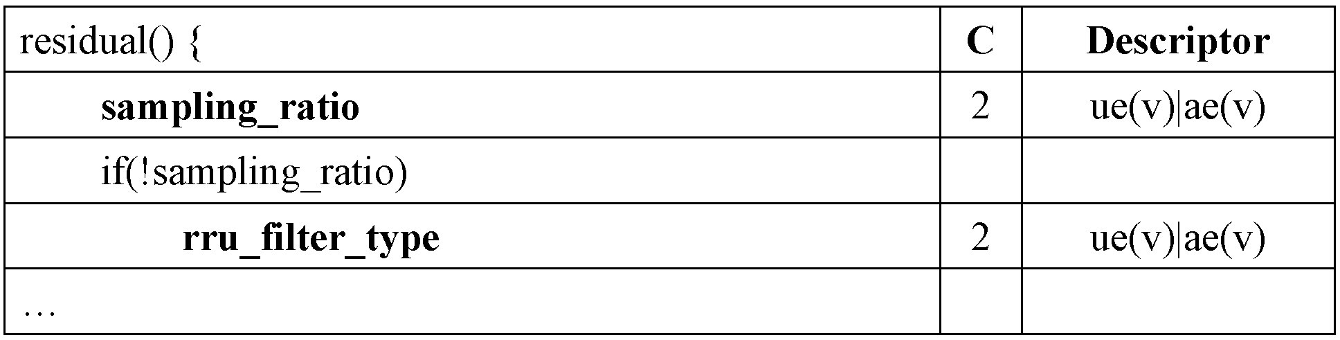
여기서, sampling_ratio 는 업 샘플링 비율 정보를 나타낼 수 있다. 이 때, sampling_ratio는 업 샘플링 비율 값 자체를 나타낼 수도 있으나, 실제 업 샘플링 비율을 도출하기 위해 사용되는 값을 나타낼 수도 있다. 일례로, 복호화기는 다음 수학식 8에 의해 실제 업 샘플링 비율을 도출할 수 있다.
[수학식 8]
Up-sampling ratio = sampling_ratio << 1
여기서, Up-sampling ratio는 업 샘플링 과정에 적용되는 실제 업 샘플링 비율을 나타낼 수 있다. 예를 들어, sampling_ratio 에 할당된 값이 2인 경우, 업 샘플링 과정에 적용되는 실제 업 샘플링 비율 값은 4일 수 있다.
또한, rru_filter_type 은 업 샘플링 필터 타입을 나타낼 수 있다. 즉, rru_filter_type 은 업 샘플링이 수행된 잔차 블록을 기반으로 생성된 복원 블록의 필터링을 위해 사용되는 업 샘플링 필터의 타입을 지시할 수 있다.
다른 실시예로, 부호화기는 상술한 실시예에서와 달리 RRU 타입을 나타내는 하나의 구문 요소를 통해 RRU 타입 정보를 복호화기로 전송할 수도 있다. 일례로, 상기 RRU 타입 정보는 구문 요소 rru_type 에 의해 나타내어질 수 있다.
이 경우, 부호화기 및 복호화기에는 RRU 타입과 업 샘플링 비율 및 RRU 필터 타입 간의 관계를 나타내는 룩업 테이블(look-up table)이 동일하게 저장되어 있을 수 있다. 상술한 바와 같이, 부호화기는 율-왜곡 최적화에 기반하여 최적의 업 샘플링 비율 및 최적의 RRU 필터 타입을 결정할 수 있다. 이 때, 부호화기는 상기 룩업 테이블을 기반으로 상기 결정된 업 샘플링 비율 및 RRU 필터 타입에 대응하는 RRU 타입을 결정할 수 있으며, 결정된 RRU 타입에 관한 정보를 하나의 구문 요소 rru_type 을 통해 복호화기로 전송할 수 있다. 복호화기는 부호화기로부터 전송된 RRU 타입 정보를 수신하여 복호화할 수 있다. 이 때, 복호화기는 상기 복호화된 RRU 타입 정보를 기반으로 현재 블록에 대한 RRU 타입을 결정할 수 있으며, 상기 결정된 RRU 타입 및 상기 저장된 룩업 테이블을 기반으로 업 샘플링 비율 및 RRU 필터 타입을 도출할 수 있다.
다시 도 7을 참조하면, 복호화기는 복호화된 RRU 타입 정보를 기반으로 상기 생성된 잔차 블록에 대해 업 샘플링을 수행할 수 있다(S740). 상기 RRU 타입 정보는 업 샘플링 비율 정보를 포함하므로, 복호화기는 상기 업 샘플링 비율 정보가 지시하는 업 샘플링 비율에 따라 잔차 블록에 대한 업 샘플링을 수행할 수 있다. 그러나, 잔차 블록에 대한 업 샘플링 비율이 1인 경우, 그 잔차 블록에 대해서는 업 샘플링이 수행되지 않을 수도 있다.
또한, 복호화기는 예측 블록 및 업 샘플링이 수행된 잔차 블록을 기반으로 복원 블록을 생성할 수 있다(S750). 이 때, 잔차 블록에 대해 업 샘플링이 수행되지 않은 경우라면, 상기 복원 블록 생성에 사용되는 잔차 블록은 업 샘플링이 수행되지 않은 잔차 블록일 수 있다.
복원 블록이 생성되면, 복호화기는 생성된 복원 블록 내의 복원 샘플 각각에 대해 필터링을 수행할 수 있다(S760). 상술한 RRU 타입 정보는 필터 타입 정보를 포함하므로, 복호화기는 상기 필터 타입 정보에 기반하여 필터링을 수행할 수 있다. 텍스쳐 영상에 대해 적용되는 필터 및 깊이 영상에 대해 적용되는 필터의 구체적인 실시예들은 상술한 바 있으므로, 여기서는 생략하기로 한다.
상술한 실시예들에 따르면, 본 발명은 RRU 타입 및/또는 RRU 모드를 기반으로 해상도 감소 갱신을 수행함으로써, 에지 등과 같은 영상의 특성들이 더 잘 유지되도록 할 수 있다. 즉, RRU 타입 정보가 사용되는 경우 영상의 특성에 따라 샘플링 비율을 달리하거나 필터 타입의 조합을 달리할 수 있으므로, 적응적인 해상도 감소 갱신이 가능해질 수 있다.
한편, 상술한 바와 같이 깊이 영상은 에지 영역을 제외한 대부분의 영역에서는 텍스쳐 영상에 비해 디테일이 중요시되지 않는 특징을 가진다. 따라서, 상술한 업 스케일링 방법 및/또는 해상도 감소 갱신 방법은, 율-왜곡 최적화 관점에서 깊이 영상에 대해 적용될 때 특히 효율적이라 할 것이다.
상술한 실시예에서, 방법들은 일련의 단계 또는 블록으로써 순서도를 기초로 설명되고 있지만, 본 발명은 단계들의 순서에 한정되는 것은 아니며, 어떤 단계는 상술한 바와 다른 단계와 다른 순서로 또는 동시에 발생할 수 있다. 또한, 당업자라면 순서도에 나타낸 단계들이 배타적이지 않고, 다른 단계가 포함되거나 순서도의 하나 또는 그 이상의 단계가 본 발명의 범위에 영향을 미치지 않고 삭제될 수 있음을 이해할 수 있을 것이다.
상술한 실시예는 다양한 양태의 예시들을 포함한다. 다양한 양태들을 나타내기 위한 모든 가능한 조합을 기술할 수는 없지만, 해당 기술 분야의 통상의 지식을 가진 자는 다른 조합이 가능합을 인식할 수 있을 것이다. 따라서, 본 발명은 이하의 특허청구범위 내에 속하는 모든 다른 교체, 수정 및 변경을 포함한다고 할 것이다.
Claims (20)
- 비트스트림을 수신하는 단계;
상기 비트스트림을 기반으로, 현재 픽쳐에 대한 예측 블록 및 잔차(residual) 블록을 생성하는 단계;
상기 비트스트림으로부터 도출된 RRU(Rrduced-Resolution Update) 타입 정보를 기반으로, 상기 잔차 블록에 대한 업 샘플링(up-sampling)을 수행하는 단계;
상기 예측 블록 및 상기 업 샘플링이 수행된 잔차 블록을 기반으로 복원 블록을 생성하는 단계; 및
상기 RRU 타입 정보를 기반으로, 상기 복원 블록에 대한 필터링을 수행하는 단계를 포함하되,
상기 RRU 타입 정보는 샘플링 비율(sampling ratio) 정보 및 필터 타입(filter type) 정보를 포함하고,
상기 업 샘플링 수행 단계에서는 상기 샘플링 비율 정보가 지시하는 샘플링 비율을 기반으로 업 샘플링을 수행하고,
상기 필터링 수행 단계에서는 상기 필터 타입 정보가 지시하는 필터를 기반으로 필터링을 수행하는 것을 특징으로 하는 영상 복호화 방법. - 제 1항에 있어서,
상기 샘플링 비율 정보는,
상기 현재 블록 내에서 상기 잔차 블록에 해당되는 영역의 주파수가 낮을수록 더 높은 값의 샘플링 비율을 지시하는 것을 특징으로 하는 영상 복호화 방법. - 제 1항에 있어서,
상기 필터링 수행 단계는,
상기 잔차 블록 내의 필터링 대상 픽셀에 대해, 소정의 크기 및 모양의 윈도우(window)를 결정하는 단계; 및
상기 윈도우 내의 픽셀을 기반으로 상기 필터링 대상 픽셀에 대한 필터링을 수행하는 단계를 더 포함하는 것을 특징으로 하는 영상 복호화 방법. - 제 3항에 있어서,
상기 현재 픽쳐가 텍스쳐 영상(texture video) 내의 픽쳐인 경우,
상기 필터 타입 정보가 지시하는 필터는 상기 윈도우 내의 픽셀을 기반으로 가중치 평균을 수행하는 양방향 가중치 필터(bi-laterally weighted filter)인 것을 특징으로 하는 영상 복호화 방법. - 제 4항에 있어서,
상기 양방향 가중치 필터는,
상기 필터링 대상 픽셀이, 에지를 포함하는 에지(edge) 영역 내의 픽셀인 경우에는 약한 스무딩(weak smoothing)을 수행하고,
상기 필터링 대상 픽셀이, 에지를 포함하지 않는 넌 에지(non-edge) 영역 내의 픽셀인 경우에는 강한 스무딩(strong smoothing)을 수행하는 것을 특징으로 하는 영상 복호화 방법. - 제 3항에 있어서,
상기 현재 픽쳐가 깊이 영상(depth video) 내의 깊이 픽쳐이고, 상기 깊이 영상에 대응하는 텍스쳐 영상(texture video) 내에서 상기 현재 픽쳐에 대응하는 텍스쳐 픽쳐가 유효(available)한 경우,
상기 필터링 수행 단계에서는,
상기 텍스쳐 픽쳐에서 상기 윈도우에 대응되는 영역 내의 텍스쳐 픽셀을 기반으로 필터링을 수행하는 것을 특징으로 하는 영상 복호화 방법. - 제 6항에 있어서,
상기 필터 타입 정보가 지시하는 필터는, 양방향 가중치 WTA 필터(bi-laterally weighted Winner_Take_All filter)이고,
상기 양방향 가중치 WTA 필터는,
상기 텍스쳐 픽셀을 기반으로 상기 윈도우 내의 깊이 픽셀 각각에 대해 가중치 스코어(weighting score)를 도출하고, 상기 깊이 픽셀 중에서 가장 높은 가중치 스코어를 갖는 깊이 픽셀의 픽셀 값을 상기 필터링 대상 픽셀에 대한 출력 값으로 결정하고,
상기 깊이 픽셀은 상기 깊이 픽쳐 내의 픽셀인 것을 특징으로 하는 영상 복호화 방법. - 제 6항에 있어서,
상기 필터 타입 정보가 지시하는 필터는 양방향 가중치 미디언 필터(bi-laterally weighted median filter)이고,
상기 양방향 가중치 미디언 필터는,
상기 텍스쳐 픽셀을 기반으로 상기 윈도우 내의 깊이 픽셀 각각에 대해 가중치 스코어(weighting score)를 도출하고, 상기 가중치 스코어를 기반으로 상기 깊이 픽셀 중에서 중간 값을 도출하고, 상기 도출된 중간 값에 해당되는 깊이 픽셀의 픽셀 값을 상기 필터링 대상 픽셀에 대한 출력 값으로 결정하고,
상기 깊이 픽셀은 상기 깊이 픽쳐 내의 픽셀인 것을 특징으로 하는 영상 복호화 방법. - 제 3항에 있어서,
상기 현재 픽쳐가 깊이 영상 내의 깊이 픽쳐이고, 상기 깊이 영상에 대응하는 텍스쳐 영상 내에서 상기 현재 픽쳐에 대응하는 텍스쳐 픽쳐가 유효하지 않은 경우,
상기 필터 타입 정보가 지시하는 필터는 양방향 가중치 미디언 필터이고,
상기 양방향 가중치 미디언 필터는,
상기 윈도우 내의 깊이 픽셀을 기반으로, 상기 깊이 픽셀 각각에 대해 가중치 스코어(weighting score)를 도출하고, 상기 가중치 스코어를 기반으로 상기 깊이 픽셀 중에서 중간 값을 도출하고, 상기 도출된 중간 값에 해당되는 깊이 픽셀의 픽셀 값을 상기 필터링 대상 픽셀에 대한 출력 값으로 결정하고,
상기 깊이 픽셀은 상기 깊이 픽쳐 내의 픽셀인 것을 특징으로 하는 영상 복호화 방법. - 제 9항에 있어서,
상기 양방향 가중치 미디언 필터는,
상기 필터링 대상 픽셀이, 에지를 포함하는 에지(edge) 영역 내의 픽셀인 경우에는 약한 스무딩을 수행하고,
상기 필터링 대상 픽셀이, 에지를 포함하지 않는 넌 에지(non-edge) 영역 내의 픽셀인 경우에는 강한 스무딩을 수행하는 것을 특징으로 하는 영상 복호화 방법. - 비트스트림을 수신하는 수신부;
상기 비트스트림을 기반으로, 현재 픽쳐에 대한 예측 블록 및 잔차(residual) 블록을 생성하는 예측 블록 및 잔차 블록 생성부;
상기 비트스트림으로부터 도출된 RRU(Rrduced-Resolution Update) 타입 정보를 기반으로, 상기 잔차 블록에 대한 업 샘플링(up-sampling)을 수행하는 업 샘플러;
상기 예측 블록 및 상기 업 샘플링이 수행된 잔차 블록을 기반으로 복원 블록을 생성하는 복원 블록 생성부; 및
상기 RRU 타입 정보를 기반으로, 상기 복원 블록에 대한 필터링을 수행하는 필터부를 포함하되,
상기 RRU 타입 정보는 샘플링 비율(sampling ratio) 정보 및 필터 타입(filter type) 정보를 포함하고,
상기 업 샘플러는 상기 샘플링 비율 정보가 지시하는 샘플링 비율을 기반으로 업 샘플링을 수행하고,
상기 필터부는 상기 필터 타입 정보가 지시하는 필터를 기반으로 필터링을 수행하는 것을 특징으로 하는 영상 복호화 장치. - 제 11항에 있어서,
상기 샘플링 비율 정보는,
상기 현재 블록 내에서 상기 잔차 블록에 해당되는 영역의 주파수가 낮을수록 더 높은 값의 샘플링 비율을 지시하는 것을 특징으로 하는 영상 복호화 장치. - 제 11항에 있어서,
상기 필터부는,
상기 잔차 블록 내의 필터링 대상 픽셀에 대해 소정의 크기 및 모양의 윈도우(window)를 결정하고, 상기 윈도우 내의 픽셀을 기반으로 상기 필터링 대상 픽셀에 대한 필터링을 수행하는 것을 특징으로 하는 영상 복호화 장치. - 제 13항에 있어서,
상기 현재 픽쳐가 텍스쳐 영상(texture video) 내의 픽쳐인 경우,
상기 필터 타입 정보가 지시하는 필터는 상기 윈도우 내의 픽셀을 기반으로 가중치 평균을 수행하는 양방향 가중치 필터(bi-laterally weighted filter)인 것을 특징으로 하는 영상 복호화 장치. - 제 14항에 있어서,
상기 양방향 가중치 필터는,
상기 필터링 대상 픽셀이, 에지를 포함하는 에지(edge) 영역 내의 픽셀인 경우에는 약한 스무딩(weak smoothing)을 수행하고,
상기 필터링 대상 픽셀이, 에지를 포함하지 않는 넌 에지(non-edge) 영역 내의 픽셀인 경우에는 강한 스무딩(strong smoothing)을 수행하는 것을 특징으로 하는 영상 복호화 장치. - 제 13항에 있어서,
상기 현재 픽쳐가 깊이 영상(depth video) 내의 깊이 픽쳐이고, 상기 깊이 영상에 대응하는 텍스쳐 영상(texture video) 내에서 상기 현재 픽쳐에 대응하는 텍스쳐 픽쳐가 유효(available)한 경우,
상기 필터부는,
상기 텍스쳐 픽쳐에서 상기 윈도우에 대응되는 영역 내의 텍스쳐 픽셀을 기반으로 필터링을 수행하는 것을 특징으로 하는 영상 복호화 장치. - 제 16항에 있어서,
상기 필터 타입 정보가 지시하는 필터는, 양방향 가중치 WTA 필터(bi-laterally weighted Winner_Take_All filter)이고,
상기 양방향 가중치 WTA 필터는,
상기 텍스쳐 픽셀을 기반으로 상기 윈도우 내의 깊이 픽셀 각각에 대해 가중치 스코어(weighting score)를 도출하고, 상기 깊이 픽셀 중에서 가장 높은 가중치 스코어를 갖는 깊이 픽셀의 픽셀 값을 상기 필터링 대상 픽셀에 대한 출력 값으로 결정하고,
상기 깊이 픽셀은 상기 깊이 픽쳐 내의 픽셀인 것을 특징으로 하는 영상 복호화 장치. - 제 16항에 있어서,
상기 필터 타입 정보가 지시하는 필터는 양방향 가중치 미디언 필터(bi-laterally weighted median filter)이고,
상기 양방향 가중치 미디언 필터는,
상기 텍스쳐 픽셀을 기반으로 상기 윈도우 내의 깊이 픽셀 각각에 대해 가중치 스코어(weighting score)를 도출하고, 상기 가중치 스코어를 기반으로 상기 깊이 픽셀 중에서 중간 값을 도출하고, 상기 도출된 중간 값에 해당되는 깊이 픽셀의 픽셀 값을 상기 필터링 대상 픽셀에 대한 출력 값으로 결정하고,
상기 깊이 픽셀은 상기 깊이 픽쳐 내의 픽셀인 것을 특징으로 하는 영상 복호화 장치. - 제 13항에 있어서,
상기 현재 픽쳐가 깊이 영상 내의 깊이 픽쳐이고, 상기 깊이 영상에 대응하는 텍스쳐 영상 내에서 상기 현재 픽쳐에 대응하는 텍스쳐 픽쳐가 유효하지 않은 경우,
상기 필터 타입 정보가 지시하는 필터는 양방향 가중치 미디언 필터이고,
상기 양방향 가중치 미디언 필터는,
상기 윈도우 내의 깊이 픽셀을 기반으로, 상기 깊이 픽셀 각각에 대해 가중치 스코어(weighting score)를 도출하고, 상기 가중치 스코어를 기반으로 상기 깊이 픽셀 중에서 중간 값을 도출하고, 상기 도출된 중간 값에 해당되는 깊이 픽셀의 픽셀 값을 상기 필터링 대상 픽셀에 대한 출력 값으로 결정하고,
상기 깊이 픽셀은 상기 깊이 픽쳐 내의 픽셀인 것을 특징으로 하는 영상 복호화 장치. - 제 19항에 있어서,
상기 양방향 가중치 미디언 필터는,
상기 필터링 대상 픽셀이, 에지를 포함하는 에지(edge) 영역 내의 픽셀인 경우에는 약한 스무딩을 수행하고,
상기 필터링 대상 픽셀이, 에지를 포함하지 않는 넌 에지(non-edge) 영역 내의 픽셀인 경우에는 강한 스무딩을 수행하는 것을 특징으로 하는 영상 복호화 장치.
Applications Claiming Priority (2)
| Application Number | Priority Date | Filing Date | Title |
|---|---|---|---|
| US201161499128P | 2011-06-20 | 2011-06-20 | |
| US61/499,128 | 2011-06-20 |
Publications (2)
| Publication Number | Publication Date |
|---|---|
| WO2012177015A2 true WO2012177015A2 (ko) | 2012-12-27 |
| WO2012177015A3 WO2012177015A3 (ko) | 2013-04-04 |
Family
ID=47423059
Family Applications (1)
| Application Number | Title | Priority Date | Filing Date |
|---|---|---|---|
| PCT/KR2012/004694 Ceased WO2012177015A2 (ko) | 2011-06-20 | 2012-06-14 | 영상 부호화/복호화 방법 및 그 장치 |
Country Status (1)
| Country | Link |
|---|---|
| WO (1) | WO2012177015A2 (ko) |
Cited By (1)
| Publication number | Priority date | Publication date | Assignee | Title |
|---|---|---|---|---|
| WO2019054561A1 (ko) * | 2017-09-15 | 2019-03-21 | 서울과학기술대학교 산학협력단 | 360도 영상 부호화 장치 및 방법, 이를 수행하기 위한 기록 매체 |
Family Cites Families (5)
| Publication number | Priority date | Publication date | Assignee | Title |
|---|---|---|---|---|
| WO2005099275A2 (en) * | 2004-04-02 | 2005-10-20 | Thomson Licensing | Complexity scalable video decoding |
| EP2014096A4 (en) * | 2006-05-04 | 2010-12-22 | Korea Electronics Telecomm | METHOD AND DEVICE FOR CODING MOBILITY IMAGES WITH MULTIPLE VIEWS |
| JPWO2009001793A1 (ja) * | 2007-06-26 | 2010-08-26 | 株式会社東芝 | 画像符号化と画像復号化の方法及び装置 |
| KR101418095B1 (ko) * | 2008-07-21 | 2014-07-11 | 에스케이 텔레콤주식회사 | 예측 방향을 이용한 영상 부호화/복호화 장치 및 방법 |
| CN105872541B (zh) * | 2009-06-19 | 2019-05-14 | 三菱电机株式会社 | 图像编码装置、图像编码方法及图像解码装置 |
-
2012
- 2012-06-14 WO PCT/KR2012/004694 patent/WO2012177015A2/ko not_active Ceased
Cited By (2)
| Publication number | Priority date | Publication date | Assignee | Title |
|---|---|---|---|---|
| WO2019054561A1 (ko) * | 2017-09-15 | 2019-03-21 | 서울과학기술대학교 산학협력단 | 360도 영상 부호화 장치 및 방법, 이를 수행하기 위한 기록 매체 |
| US10986342B2 (en) | 2017-09-15 | 2021-04-20 | Foundation For Research And Business, Seoul National University Of Science And Technology | 360-degree image encoding apparatus and method, and recording medium for performing the same |
Also Published As
| Publication number | Publication date |
|---|---|
| WO2012177015A3 (ko) | 2013-04-04 |
Similar Documents
| Publication | Publication Date | Title |
|---|---|---|
| KR20240073227A (ko) | 영상 부호화 및 복호화 장치 및 그 방법 | |
| JP5663093B2 (ja) | 参照ピクチャー処理のための最適化されたフィルタ選択 | |
| JP6100833B2 (ja) | 多視点信号コーデック | |
| JP5044057B2 (ja) | フィルタを選択する方法及び装置 | |
| CN103026707B (zh) | 使用用于视频编码的高级运动模型的参考处理 | |
| JP5529293B2 (ja) | メタデータによる時間スケーリングのためのエッジエンハンスメントのための方法 | |
| JP6245888B2 (ja) | エンコーダおよび符号化方法 | |
| JP2015057919A (ja) | 動き補償方法及び動き補償装置 | |
| CN115552905A (zh) | 用于图像和视频编码的基于全局跳过连接的cnn滤波器 | |
| CN104718761A (zh) | 视频编码/解码方法、装置、程序、记录介质 | |
| CN117041555A (zh) | 使用插值滤波器进行帧内预测的方法和装置 | |
| KR20150010903A (ko) | 모바일 단말 화면을 위한 3k해상도를 갖는 디스플레이 영상 생성 방법 및 장치 | |
| KR20120009648A (ko) | 깊이영상 부호화를 위한 율-왜곡 최적화 장치 및 방법 | |
| JP7384974B2 (ja) | 適応乗算係数を用いた画像フィルタリングのための方法および装置 | |
| JP2014171097A (ja) | 符号化装置、符号化方法、復号装置、および、復号方法 | |
| JPWO2014050741A1 (ja) | 映像符号化方法および装置、映像復号方法および装置、それらのプログラム及び記録媒体 | |
| CN116848843A (zh) | 可切换的密集运动向量场插值 | |
| KR102163477B1 (ko) | 비디오 부호화 및 복호화 방법, 그를 이용한 장치 | |
| CN103548350B (zh) | 图像编码设备和图像解码设备 | |
| KR20130037188A (ko) | 영상 부호화 방법과 영상 복호화 방법 | |
| KR20210024113A (ko) | 양방향 인트라 예측을 위한 참조 샘플 보간 방법 및 장치 | |
| WO2013051897A1 (ko) | 영상 부호화 방법과 영상 복호화 방법 | |
| WO2012177015A2 (ko) | 영상 부호화/복호화 방법 및 그 장치 | |
| KR20200004348A (ko) | 타겟 영역 수정을 통해 비디오 신호를 처리하는 방법 및 장치 | |
| KR20130098121A (ko) | 적응적 보간 필터를 이용하는 영상 부호화/복호화 장치 및 영상을 부호화/복호화하는 방법 |
Legal Events
| Date | Code | Title | Description |
|---|---|---|---|
| 121 | Ep: the epo has been informed by wipo that ep was designated in this application |
Ref document number: 12802516 Country of ref document: EP Kind code of ref document: A2 |
|
| NENP | Non-entry into the national phase |
Ref country code: DE |
|
| 122 | Ep: pct application non-entry in european phase |
Ref document number: 12802516 Country of ref document: EP Kind code of ref document: A2 |