WO2013001981A1 - ブーツバンド - Google Patents
ブーツバンド Download PDFInfo
- Publication number
- WO2013001981A1 WO2013001981A1 PCT/JP2012/064218 JP2012064218W WO2013001981A1 WO 2013001981 A1 WO2013001981 A1 WO 2013001981A1 JP 2012064218 W JP2012064218 W JP 2012064218W WO 2013001981 A1 WO2013001981 A1 WO 2013001981A1
- Authority
- WO
- WIPO (PCT)
- Prior art keywords
- claw
- end side
- engagement
- band
- tool
- Prior art date
- Legal status (The legal status is an assumption and is not a legal conclusion. Google has not performed a legal analysis and makes no representation as to the accuracy of the status listed.)
- Ceased
Links
Images






Classifications
-
- F—MECHANICAL ENGINEERING; LIGHTING; HEATING; WEAPONS; BLASTING
- F16—ENGINEERING ELEMENTS AND UNITS; GENERAL MEASURES FOR PRODUCING AND MAINTAINING EFFECTIVE FUNCTIONING OF MACHINES OR INSTALLATIONS; THERMAL INSULATION IN GENERAL
- F16B—DEVICES FOR FASTENING OR SECURING CONSTRUCTIONAL ELEMENTS OR MACHINE PARTS TOGETHER, e.g. NAILS, BOLTS, CIRCLIPS, CLAMPS, CLIPS OR WEDGES; JOINTS OR JOINTING
- F16B2/00—Friction-grip releasable fastenings
- F16B2/02—Clamps, i.e. with gripping action effected by positive means other than the inherent resistance to deformation of the material of the fastening
- F16B2/06—Clamps, i.e. with gripping action effected by positive means other than the inherent resistance to deformation of the material of the fastening external, i.e. with contracting action
- F16B2/08—Clamps, i.e. with gripping action effected by positive means other than the inherent resistance to deformation of the material of the fastening external, i.e. with contracting action using bands
-
- F—MECHANICAL ENGINEERING; LIGHTING; HEATING; WEAPONS; BLASTING
- F16—ENGINEERING ELEMENTS AND UNITS; GENERAL MEASURES FOR PRODUCING AND MAINTAINING EFFECTIVE FUNCTIONING OF MACHINES OR INSTALLATIONS; THERMAL INSULATION IN GENERAL
- F16D—COUPLINGS FOR TRANSMITTING ROTATION; CLUTCHES; BRAKES
- F16D3/00—Yielding couplings, i.e. with means permitting movement between the connected parts during the drive
- F16D3/84—Shrouds, e.g. casings, covers; Sealing means specially adapted therefor
- F16D3/843—Shrouds, e.g. casings, covers; Sealing means specially adapted therefor enclosed covers
- F16D3/845—Shrouds, e.g. casings, covers; Sealing means specially adapted therefor enclosed covers allowing relative movement of joint parts due to the flexing of the cover
-
- F—MECHANICAL ENGINEERING; LIGHTING; HEATING; WEAPONS; BLASTING
- F16—ENGINEERING ELEMENTS AND UNITS; GENERAL MEASURES FOR PRODUCING AND MAINTAINING EFFECTIVE FUNCTIONING OF MACHINES OR INSTALLATIONS; THERMAL INSULATION IN GENERAL
- F16J—PISTONS; CYLINDERS; SEALINGS
- F16J3/00—Diaphragms; Bellows; Bellows pistons
- F16J3/04—Bellows
- F16J3/041—Non-metallic bellows
- F16J3/042—Fastening details
-
- F—MECHANICAL ENGINEERING; LIGHTING; HEATING; WEAPONS; BLASTING
- F16—ENGINEERING ELEMENTS AND UNITS; GENERAL MEASURES FOR PRODUCING AND MAINTAINING EFFECTIVE FUNCTIONING OF MACHINES OR INSTALLATIONS; THERMAL INSULATION IN GENERAL
- F16D—COUPLINGS FOR TRANSMITTING ROTATION; CLUTCHES; BRAKES
- F16D3/00—Yielding couplings, i.e. with means permitting movement between the connected parts during the drive
- F16D3/16—Universal joints in which flexibility is produced by means of pivots or sliding or rolling connecting parts
- F16D3/20—Universal joints in which flexibility is produced by means of pivots or sliding or rolling connecting parts one coupling part entering a sleeve of the other coupling part and connected thereto by sliding or rolling members
- F16D3/22—Universal joints in which flexibility is produced by means of pivots or sliding or rolling connecting parts one coupling part entering a sleeve of the other coupling part and connected thereto by sliding or rolling members the rolling members being balls, rollers, or the like, guided in grooves or sockets in both coupling parts
- F16D3/223—Universal joints in which flexibility is produced by means of pivots or sliding or rolling connecting parts one coupling part entering a sleeve of the other coupling part and connected thereto by sliding or rolling members the rolling members being balls, rollers, or the like, guided in grooves or sockets in both coupling parts the rolling members being guided in grooves in both coupling parts
- F16D2003/22316—Means for fastening or attaching the bellows or gaiters
-
- Y—GENERAL TAGGING OF NEW TECHNOLOGICAL DEVELOPMENTS; GENERAL TAGGING OF CROSS-SECTIONAL TECHNOLOGIES SPANNING OVER SEVERAL SECTIONS OF THE IPC; TECHNICAL SUBJECTS COVERED BY FORMER USPC CROSS-REFERENCE ART COLLECTIONS [XRACs] AND DIGESTS
- Y10—TECHNICAL SUBJECTS COVERED BY FORMER USPC
- Y10T—TECHNICAL SUBJECTS COVERED BY FORMER US CLASSIFICATION
- Y10T24/00—Buckles, buttons, clasps, etc.
- Y10T24/14—Bale and package ties, hose clamps
Definitions
- the present invention relates to a boot band for fixing a member to be fastened to a mating member by fastening a member to be fastened such as a boot made of rubber, resin, or the like.
- the boot band is used, for example, for a constant velocity joint that transmits engine driving force from a driving shaft to a driven shaft.
- the power transmission portion is covered with a bellows-like boot, and grease is sealed inside the boot.
- the boot band is wound around the outer periphery of both ends of the boot and reduced in diameter, thereby tightening the boot and preventing the grease from leaking from the inside of the boot.
- Such a boot band is provided with a pair of tool claws so that it can be tightened by a tightening tool, and a tightening force in the reduced diameter direction is applied via the pair of tool claws.
- FIG. 12 shows a conventional boot band 1.
- the boot band 1 includes a band body 3 made of a thin metal plate, and is tightened in a state where a member to be tightened such as a boot is wound in a ring shape so as to penetrate the inside.
- the band body 3 When the band body 3 is wound, the band body 3 has an outer overlapping portion 4 and an inner overlapping portion 5 that overlap each other.
- the first tool claw 7 is formed on the distal end side of the outer overlapping portion 4 of the boot band 1, while the inner overlapping portion 5 is paired with the first tool claw 7.
- a second tool claw 6 is formed.
- the pair of tool claws 7 and 6 are tool claws for fastening the ring-shaped band main body 3 in the direction of diameter reduction, and hooks (not shown) of the fastening tool are hooked.
- the second tool nail 6 is press-molded so as to rise outward in the radial direction, whereby an opening 6b that opens toward the first tool nail 7 is formed in the second tool nail 6, and an opening is formed.
- the outer wall of the portion 6b is a presser portion 6a.
- the tip (free end) of the outer overlapping portion 4 is a terminal portion 14 that extends flatly than the first tool claw 7, and the terminal portion 14 extends from the opening 6 b to the second tool claw 6. It has come in.
- the terminal portion 14 that has entered the opening 6b is pressed from the outside by the pressing portion 6a, and is prevented from being lifted radially outward.
- Patent Document 1 describes a boot band that can be tightened in one action by pressing a terminal portion provided at the tip of an outer overlapping portion with a second tool claw as in FIG.
- FIG. 12A shows the conventional boot band, as shown in FIG. 12A, a plurality of engagement holes 12 and 13 are formed along the length direction in the outer overlapping portion 4, and the engagement holes 12 are formed in the inner overlapping portion 5. , 13 is formed.
- the engaging claw 11 rises in an inclined manner toward the distal end side of the outer overlapping portion 4.
- FIG. 12A shows the ring-shaped band main body 3 in a temporarily fixed state. In the temporarily fixed state, the engaging claw 11 is engaged with the distal end side engaging hole 12 positioned on the distal end side of the outer overlapping portion 4.
- a tightening force F see FIG.
- the conventional boot band 1 described above has a problem that the inner overlapping portion 5 buckles when the band body 3 is tightened.
- the mechanism by which buckling occurs will be described with reference to FIG.
- FIG. 12A shows a temporarily fixed state in which the band main body 3 is in a ring shape when the engaging claw 11 is engaged with the distal end side engaging hole 12.
- a tightening force F is applied to the band body 3 by the tightening tool
- the distal end side engagement hole 12 slides on the back surface 11a of the engagement claw 11 as shown in FIG. While sliding over the engaging claw 11, it slides.
- the rear side of the front end side engagement hole 12 in the outer overlapping portion 4 is twisted with the back surface 11a of the engagement claw 11, and the sliding is locked.
- Patent Document 1 discloses a boot band having a structure that enables tightening in one action by pressing a terminal portion provided at the tip of an outer overlapping portion with a second tool claw as in FIG. The structure which prevented the buckling generation
- a slit or the like is formed between the distal end side engagement hole 12 and the first tool claw 7 in the outer overlapping portion 4 to reduce the rigidity therebetween.
- the outer overlapping portion 4 can slide so as to press between the engaging claw 11 and the second tool claw 6 in the inner overlapping portion 5 when the band body is tightened.
- the load by which the outer overlapping portion presses the back surface of the engaging claw 11 in the center direction is reduced.
- Patent Document 1 discloses that a rib or the like is formed between the second tool claw 6 and the engagement claw 11 in the inner overlapping portion 5 to increase the rigidity between the second tool claw 6 and the engagement claw 11. It is described that the buckling load is increased, thereby preventing the occurrence of buckling 16 between the engaging claw 11 and the second tool claw 6 in the inner overlapping portion 5.
- a rubber boot is used in addition to a hard resin boot. Rubber boots are softer than resin boots, so the boot band used for tightening can be made thinner or narrower than the boot band used for resin boots to reduce the cross-sectional area. Therefore, there is an advantage that the weight can be reduced.
- the plate thickness is thin, but the rigidity is low, so the buckling resistance during tightening is reduced. In this case, even with the buckling prevention structure described in Patent Literature 1, the buckling load cannot be sufficiently increased, and it may be difficult to prevent the occurrence of buckling. For this reason, there is an increasing demand for a boot band having a structure capable of preventing the occurrence of buckling even when the plate thickness is thin.
- the present invention has been made in consideration of such circumstances, and is a boot band having a structure capable of being tightened with one action as in Patent Document 1, and further reducing the plate thickness or the plate width.
- An object of the present invention is to provide a boot band that can prevent buckling from occurring even when the strap is narrowed.
- the boot band of the present invention includes a band main body wound around an outer periphery of a member to be tightened in a ring state in which an outer overlapping portion and an inner overlapping portion overlap each other, and a first formed on the distal end side of the outer overlapping portion.
- a tool claw, a flat terminal portion formed in an outer overlapping portion at the tip of the first tool claw, an opening into which the terminal portion can be inserted, and a terminal portion inserted into the opening are pressed from the outside.
- a plurality of second tool claws that are formed in the inner overlapping portion with a pressing portion and that are tightened by reducing the diameter of the band main body together with the first tool claws, and a length direction of the outer overlapping portion;
- An engaging hole and an engaging claw formed on the inner overlapping part in a state of rising in an inclined manner toward the tip end side of the outer overlapping part, the engaging claw extending in the length direction of the outer overlapping part Located on the tip side
- the tightening force in the diameter reducing direction is applied to the band main body so that the front-end side engagement hole gets over the engagement claw, and the subsequent engagement hole following the front-end side engagement hole
- a boot band that engages with the engaging claw, wherein a guide means facing the engaging claw is provided at a rear end portion of the distal end side engaging hole.
- the guide means is an R portion provided on the inner overlapping portion side in the rear end portion of the distal end side engagement hole.
- the guide means has an inclined portion along the engaging claw.
- the guide means is a guide claw that rises in an inclined manner from the rear end portion of the front end side engagement hole along the rising direction of the engagement claw, and the inclined portion is opposed to the engagement claw in the guide claw. It is preferable to be provided on the surface.
- the guide means is an inner surface of a rear end portion facing the engagement claw in the front end side engagement hole, and the inclined portion is provided on an inner surface of the rear end portion.
- the guide means is able to climb over the back surface of the engaging claw by the tightening force in the diameter reducing direction, and the inclination angle of the back surface of the engaging claw is an initial angle ⁇ that is passed over and an end angle ⁇ that is passed over after this is reached. It is preferable that the relationship is ⁇ ⁇ . Further, the guide means is able to climb over the back surface of the engaging claw by the tightening force in the diameter reducing direction, and the inclination angle of the back surface of the engaging claw is an initial angle ⁇ that is passed over and an end angle ⁇ that is passed over after this is reached. It is preferable that the relationship of ⁇ ⁇ ⁇ is satisfied with respect to the angle ⁇ of the inclined portion of the guide means.
- the outer overlapping portion is bent with the engagement claw when the band body is tightened. Disappears. For this reason, the outer overlapping portion rides on the back surface of the engaging claw, further reduces the resistance when getting over, and can move smoothly and get over. As a result, an overload is not applied to the inner overlapping portion, and even when the band main body is thinned, it sits on the portion between the engaging claw of the inner overlapping portion and the second tool claw. No bending occurs.
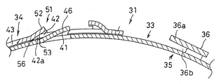
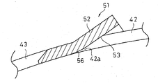
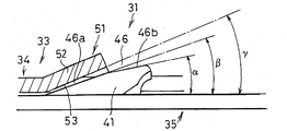
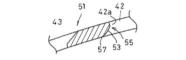
- the boot band of 1st Embodiment of this invention is shown, (a) is a top view, (b) is sectional drawing. It is a front view which shows the state which made the boot band ring shape. It is sectional drawing which shows the principal part of a boot band. It is an expanded sectional view which shows a guide means. (A), (b), (c), (d) is sectional drawing which shows the fastening operation
- (First embodiment) 1 to 7 show a first embodiment of the present invention.
- the boot band 31 is formed by a band body 33 made of a thin metal plate.
- the band main body 33 is formed in a band shape by press punching a metal thin plate, and is used for tightening a member to be tightened (not shown) such as a boot in a state of being wound from a band shape into a ring shape.
- the band main body 33 wound in a ring shape is formed with an outer overlapping portion 34 and an inner overlapping portion 35 that overlap each other, and pulls these overlapping portions 34 and 35 in the direction of diameter reduction (the direction of arrow F in FIG. 2).
- the member to be tightened is tightened.
- a first tool claw 37 is formed on the distal end side (the right end side in FIG. 1) of the outer overlapping portion 34 so as to rise radially outward.
- a flat end portion 38 is formed at the free end which is the tip (right end) further than the first tool pawl 37.
- the terminal portion 38 is formed so as to face a second tool claw 36 to be described later.
- a second tool claw 36 that is paired with the first tool claw 37 is formed in the inner overlapping portion 35.
- claw 36 is formed in the inner overlapping part 35 at the standing shape, and has the opening part 36b and the pressing part 36a.
- the opening 36b is open on the first tool claw 37 side, and thus the terminal portion 38 of the outer overlapping portion 34 can be inserted.
- the pressing portion 36a covers the outside of the opening portion 36b and acts to press the terminal portion 38 inserted into the opening portion 36b from the outside.
- the terminal portion 38 of the outer overlapping portion 34 is pressed against the pressing portion 36a of the second tool claw 36 provided on the inner overlapping portion 35, so that the outer overlapping portion 34 does not float when the band main body 33 is tightened. Therefore, an operation of pressing the outer overlapping portion 4 in the inner direction is not necessary. Therefore, the tightening can be performed only by the tightening operation in the diameter reducing direction, and the tightening can be performed by one action, so that the workability is improved.
- the engaging claw 41 is formed on the inner overlapping portion 35 by pressing and raising.
- the engaging claw 41 is formed in the inner overlapping portion 35 in a state of rising in an inclined direction facing the distal end side (the right end side in FIGS. 3 and 4) of the outer overlapping portion 34. That is, as shown in FIGS. 3 and 4, the engaging claw 41 rises with an inclination that gradually increases toward the distal end side of the outer overlapping portion 34.
- the engaging claw 41 here is an engaging claw formed on the inner overlapping portion 35 so as to correspond to the front end side of the outer overlapping portion 34, and the rear side (outer overlapping portion) of the engaging claw 41 in the inner overlapping portion 35.
- a second engagement claw 47 is further formed at a predetermined interval on the side far from the side 34. Similarly to the engagement claw 41, the second engagement claw 47 is also formed in a state of rising in an inclined shape facing the front end side (the right end side in FIGS. 3 and 4) of the outer overlapping portion 34.
- a plurality of engagement holes 42, 43, 44 are formed in the outer overlapping portion 34 along the length direction.
- the engagement hole 42 is located at the most distal end side (the right end side in FIG. 1) of the outer overlapping portion 34, thereby forming the distal end side engagement hole 42.
- the engagement hole 43 is formed on the rear side of the front end side engagement hole 42, thereby forming a subsequent engagement hole 43.
- the engagement claw 41 moves relatively from the distal end side engagement hole 42 to the subsequent engagement hole 43 and engages with the subsequent engagement hole 43.
- the engagement hole 44 is a third engagement hole and is formed further rearward than the subsequent engagement hole 43.
- guide means 51 is formed in the front end side engagement hole 42.
- the guide means 51 is formed by a guide claw 52 that rises from a rear end portion (left end portion in FIGS. 3 and 4) 42a.
- the guide claw 52 is formed by press molding or the like so as to rise in an inclined manner from the rear end portion (left end portion) 42 a of the front end side engagement hole 42 toward the engagement claw 41. . That is, the guide claw 52 rises with an inclination that gradually increases toward the engagement claw 41.
- the lower surface of the guide claw 52 is opposed to the back surface 46 of the engagement claw 41 as the guide claw 52 rises in an inclined manner.
- the lower surface of the guide claw 52 facing the back surface 46 of the engagement claw 41 is an inclined portion 53 that is inclined in the same direction as the back surface 46 of the engagement claw 41.
- the base portion of the inclined portion 53 that is, the rearmost end portion (the left end portion in the drawing) is a gentle R portion 56.
- the R portion 56 is formed on the inner overlapping portion 34 side in the rear end portion 42 a of the front end side engagement hole 42, and the inclined portion 53 is formed so as to continue from the R portion 56.
- the inclined portion 53 starts from the R portion 56 and is inclined along the inclination of the back surface 46 of the engaging claw 41.
- the inclined portion 53 smoothly runs on the back surface of the engaging claw 41. Thus, it acts so as to slide without causing the engagement claws.
- a second guide claw 57 having the same shape as the guide claw 52 is also formed in the subsequent engagement hole 43 (see FIG. 1).
- the second guide claw 57 corresponds to the second engaging claw 47, and an R portion and an inclined portion that are inclined in the same direction are formed on the lower surface of the second engaging claw 47 facing the back surface.
- Such a second guide claw 57 smoothly rides on the back surface of the second engaging claw 47 when the band main body 33 is temporarily tightened from when the band main body 33 is temporarily fixed, so that the engagement with the engaging claw is prevented. It acts to slide without occurring. Thereby, when the band main body 33 is tightened, the diameter can be reduced more smoothly.
- the second guide claw 57 can be omitted when a smooth diameter reduction can be ensured only by the action of the guide claw 52.
- FIG. 5A shows a temporarily fixed state in which the band body 33 is ring-shaped.
- the engaging claw 41 enters and engages with the engaging hole 42 on the distal end side, and the ring state of the band main body 33 is maintained by this engagement.
- FIG. 5B shows a state in which the first tool claw 37 and the second tool claw 36 are hooked with the claw portion of the tightening tool and the band main body 33 is given a tightening force F in the diameter reducing direction with respect to the state of FIG. Indicates the state of action.
- the front end side engaging hole 42 of the outer overlapping portion 34 starts to ride on the engaging claw 41 by the tightening force F in the diameter reducing direction.
- the distal end side engagement hole 42 rides on the engagement claw 41, it smoothly rides on the back surface 46 of the engagement claw 41 by the R portion 56 at the base of the inclined portion 53 of the guide claw 52 and the back surface of the engagement claw 41. 46 is slid.
- FIG. 5C shows a state where the diameter of the band body 33 is further reduced from the state of FIG.
- the inclined portion 53 of the guide claw 52 passes through the back surface 46 of the engaging claw 41, and the outer overlapping portion 34 immediately before sliding over the back surface 46 of the engaging claw 41.
- the guide claw 52 of the distal end side engagement hole 42 slides in a state where it smoothly rides on the back surface 46 of the engagement claw 41, so that the band body 33 can be smoothly reduced in diameter. it can.
- the inclined portion 53 smoothly rides on the back surface 46 of the engagement claw 41 and slides on the back surface 46 of the engagement claw 41, so that the front end side engagement hole 42 causes the engagement claw 41 to move. You can get over.
- the subsequent engagement hole 43 formed on the rear side relatively moves to the engagement claw 41, and this relative movement causes the engagement claw 41 to enter and engage with the subsequent engagement hole 43 (FIG. 5). (D)).
- the band main body 33 can be kept in the reduced diameter state further tightened from the ring state.
- the terminal portion 38 of the outer overlapping portion 34 enters the opening 36b of the second tool claw 36 and is pressed against the pressing portion 36a, so that the outer overlapping portion 34 does not float outward. .
- the operation of pressing the outer overlapping portion 34 inward is unnecessary, and the tightening can be performed with one action, and the operability of tightening is improved.
- the outer overlapping portion 33 and the engaging claw 41 may bend when the distal end side engaging hole 42 rides on the back surface 4 of the engaging claw 41.
- the band main body 33 is smoothly reduced in diameter. For this reason, an overload load does not act on the portion between the engaging claw 41 and the second tool claw 36 in the inner overlapping portion 35, and the inner overlapping is possible even when the band body 33 is thin. It is possible to prevent buckling from occurring in a portion of the portion 35 between the engaging claw 41 and the second tool claw 36.
- FIG. 6 shows the structure of the back surface 46 of the engaging claw 41 in this embodiment.
- the inclination of the rear face 46 of the engaging claw 41 is made into two steps of an initial inclined part 46a at the initial stage of getting over the engaging hole 42 and an end inclined part 46b at the final stage of getting over the following. .
- the inclination angle (overriding initial angle) ⁇ of the initial inclined portion 46a and the inclination angle (overcoming final angle) ⁇ of the final inclined portion 46b are in a relationship of ⁇ ⁇ . This makes it possible to match the inclination angles ⁇ and ⁇ with the magnitude of the reaction force from the boot. That is, in the initial stage of tightening of the band main body 33 shown in FIG. 5B, since the reaction force of the boot against the band main body 33 is small, an excessive load is applied to the band main body 33 even when the initial climb angle ⁇ is large. There is little influence.
- the inclination angle ⁇ is set to about 12 °, and the inclination angle ⁇ is set to about 19 °.
- FIG. 7 shows a form in which the inclination angle of the inclined portion 53 of the guide claw 52 is adjusted in addition to the inclination angle of the engaging claw 41 with respect to the back surface 46 of FIG.
- the back 46 of the engaging claw 41 is formed with an initial inclined portion 46a that is inclined at the overriding initial angle ⁇ and a final inclined portion 46b that follows the initial inclined portion 46a while being inclined at the overcoming final angle ⁇ .
- the relationship of ⁇ ⁇ is the same as in FIG.
- the relationship of ⁇ ⁇ ⁇ is established with respect to the inclination angle ⁇ of the inclined portion 53 of the guide claw 52 of the distal end side engagement hole 42. Since the guide claw 52 of the distal end side engagement hole 42 rises in an inclined manner toward the engagement claw 41, the inclined portion 53 is inclined in the same direction as the back surface 46 of the engagement claw 41.
- the inclined portion 53 can 46 is in a state of rising larger than the inclined portions 46a and 46b. That is, the guide claw 52 having the inclined portion 53 rises higher than the engaging claw 41 toward the distal end side, and toward the distal end side between the inclined portion 53 and the back surface 46 of the engaging claw 41. Inevitably there is a gap.
- the inclination angle ⁇ of the inclined portion 53 of the guide claw 52 is made larger than the inclination angles ⁇ and ⁇ of the back surface 46 of the engaging claw 41, so that there is a gap between the inclined portion 53 and the back surface 46 of the engaging claw 41. Therefore, when the band body 33 is subjected to the tightening force F in the diameter reducing direction, the inclined portion 53 is initially inclined to face the initial inclined portion 46a on the back surface 46 of the engaging claw 41.
- the R portion 56 of the root portion of the inclined portion 53 of the guide claw 52 contacts the initial inclined portion 46a without the tip portion (right side in the figure) of 53 contacting the initial inclined portion 46a.
- the inclination angle ⁇ of the inclined portion 53 of the guide claw 52 is set to be larger than the inclination angle (overcoming end angle) ⁇ of the engagement claw 41. Therefore, it does not come into contact with the final inclined portion 46b of the tip end portion (right side in the figure) of the guide claw 52. Further, the inclination angle 53 of the guide claw 52 and the back surface of the engagement claw 41 are set by setting the inclination angle (override end angle) ⁇ of the final inclination portion 46b to be smaller than the inclination angle (overflow initial angle) ⁇ of the initial inclination portion 46a.
- the contact pressure with 46 can be lowered, and the frictional force generated between them is also reduced. Accordingly, even in the final tightening stage, the inclined portion 53 slides smoothly in a state where it rides on the final inclined portion 46b.
- the overload does not act on the portion between the engaging claw 41 and the second tool claw 36 in the inner overlapping portion 35. Thereby, it is possible to reliably prevent buckling from occurring in a portion between the engagement claw 41 and the second tool claw 36 of the inner overlapping portion 35.
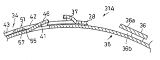
- (Second Embodiment) 8 and 9 show a boot band 31A according to the second embodiment of the present invention.
- the guide means 51 is the inner surface 55 of the rear end portion 42 a facing the engagement claw 41 in the front end side engagement hole 42, and the inclined portion 53 is provided on the inner surface 55. It is different from the embodiment, and other constituent members are the same as those of the first embodiment.
- the front side engagement hole 42 and the rear subsequent engagement hole 43 are formed along the length direction of the outer overlapping part 34 with respect to the engaging claw 41 of the inner overlapping part 35.
- the inclined portion 53 of the inner surface 55 of the front end side engagement hole 42 is formed by press molding or coining so as to be inclined in the same direction as the rear surface 46 along the inclination of the rear surface 46 of the engagement claw 41.
- an R portion 57 is formed at the root portion, that is, the end portion (the left end portion in the drawing) of the inclined portion 53.
- the R portion 57 is formed on the inner overlapping portion 34 side in the rear end portion 42 a of the front end side engagement hole 42, and the inclined portion 53 is formed so as to continue from the R portion 57.
- the inner surface 55 of the distal end side engagement hole 42 having the inclined portion 53 and the R portion 57 constitutes the guide means 51 of the present invention. That is, the inclined portion 53 is formed along the inclination of the back surface 46 of the engaging claw 41, and the base portion R portion 57 of the inclined portion 53 is formed, so that the band body 33 is tightened in the reduced diameter direction.
- the inclined portion 53 acts to smoothly ride on the back surface 46 of the engaging claw 41 by the R portion 57. As a result, the band body 33 can be smoothly tightened at the initial stage of tightening, and buckling can be reliably prevented from occurring in the portion between the engagement claw 41 and the second tool claw 36 of the inner overlapping portion 35. can do.
- the rear surface 46 of the engaging claw 41 is made up of two stages, an initial inclined part 46a and a subsequent inclined part 46b, as in FIG. 6, and the inclination angle ⁇ of the initial inclined part 46a and the final inclined part 46b.
- the inclination angle ⁇ can be in a relationship of ⁇ ⁇ .
- the relationship of ⁇ ⁇ ⁇ can be established with respect to the inclination angle ⁇ of the inclined portion 53 constituting the inner surface 55 of the distal end side engagement hole 42.
- the inclined portion 53 rises larger than the inclined portions 46a and 46b. It becomes a state.
- a gap is inevitably generated toward the distal end side between the inclined portion 53 of the inner surface 55 of the distal end side engagement hole 42 and the back surface 46 of the engagement claw 41.
- the distal end portion (the right side in the drawing) of the inner surface 55 of the distal end side engagement hole 42 does not come into contact with the engagement claw 41 in both the initial stage and the final stage when the band main body 33 is tightened in the diameter reducing direction.
- the R portion 57 at the base portion of the inclined portion 53 contacts the initial inclined portion 46 a of the engaging claw 41.
- the inclined portion 53 smoothly rides on and slides on the initial inclined portion 46a by the R portion 57 at the base portion, there is no twisting, and the overload load caused by the twisting in the initial tightening is on the inside. There is no effect on the portion of the overlapping portion 35 between the engaging claw 41 and the second tool claw 36.
- the contact pressure between the inclined portion 53 and the back surface 46 of the engaging claw 41 can be lowered, and the frictional force generated between them can also be reduced. Accordingly, since the inclined portion 53 slides smoothly in a state where it rides on the final inclined portion 46b, the inclined portion 53 and the engaging claw 41 do not turn, and the overload load caused by the turn overlaps inside. It does not act on the portion between the engaging claw 41 and the second tool claw 36 of the part 35. As described above, it is possible to more reliably prevent the buckling from occurring in the portion between the engaging claw 41 and the second tool claw 36 of the inner overlapping portion 35 in all regions from the initial tightening to the final tightening operation. Can do. Thus, even when the band main body 33 is made thin, it is possible to reliably prevent buckling from occurring in the portion between the engaging claw 41 and the second tool claw 36 of the inner overlapping portion 35. Can do.
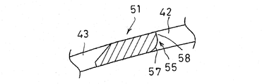
- the guide means 51 is an R portion 57 provided by press molding or coining on the inner overlapping portion 35 side of the inner surface 55 of the rear end portion 42a facing the engagement claw 41 in the front end side engagement hole 42.
- the inclined portion 53 is not provided, and other components are the same as those of the second embodiment.
- the R portion 57 in this modified embodiment is formed at the root portion of the rear end portion 42 a of the front end side engagement hole 42, and the straight portion 58 is continuously formed on the R portion 57.
- the root portion R portion 57 smoothly moves to the initial inclined portion 46a. Since it rides on and slides, it does not produce a turn, and an overload load caused by a turn at the initial stage of tightening acts on a portion between the engaging claw 41 and the second tool claw 36 of the inner overlapping portion 35. There is nothing.
- the band main body 33 when the band main body 33 is tightened, the outer overlapping portion 33 and the engaging claw 41 are bent when the distal end side engaging hole 42 rides on the back surface 4 of the engaging claw 41.
- the band main body 33 is smoothly reduced in diameter. For this reason, an overload load does not act on the portion between the engaging claw 41 and the second tool claw 36 in the inner overlapping portion 35, and the inner overlapping is possible even when the band body 33 is thin. It is possible to prevent buckling from occurring in a portion of the portion 35 between the engaging claw 41 and the second tool claw 36.
- the flat terminal portion 38 is formed at the tip of the outer overlapping portion 33, and the opening 36 b and the presser portion of the second tool claw 36 of the inner overlapping portion 35. 36a is formed, and when the band main body 33 is tightened, the terminal portion 38 is pressed against the pressing portion 36a of the second tool claw 36 to prevent the outer overlapping portion 33 from being lifted.
Landscapes
- Engineering & Computer Science (AREA)
- General Engineering & Computer Science (AREA)
- Mechanical Engineering (AREA)
- Clamps And Clips (AREA)
Abstract
Description
また、特許文献1には、内側重なり部5における第2工具爪6と係合爪11の間にリブ等を形成することにより、第2工具爪6と係合爪11の間の剛性を高くし耐座屈荷重を高め、これにより内側重なり部5における係合爪11と第2工具爪6との間の座屈16の発生を防止することが記載されている。
又、前記ガイド手段は、前記係合爪に沿った傾斜部を有していることが好ましい。
又、前記ガイド手段は、前記先端側係合孔の後端部から係合爪の立上がり方向に沿って傾斜状に立ち上がるガイド爪であり、前記傾斜部は前記ガイド爪における係合爪との対向面に設けられていることが好ましい。
又、前記ガイド手段は、前記先端側係合孔における前記係合爪と対向する後端部の内面であり、前記傾斜部は前記後端部の内面に設けられていることが好ましい。
又、前記縮径方向の締め付け力によって前記ガイド手段が前記係合爪の背面を乗り越え可能となっており、前記係合爪の背面の傾斜角度が乗り越え初期角度β及びこれに続く乗り越え終期角度αの2段に形成されると共に、α<βの関係となっていることが好ましい。
又、前記縮径方向の締め付け力によって前記ガイド手段が前記係合爪の背面を乗り越え可能となっており、前記係合爪の背面の傾斜角度が乗り越え初期角度β及びこれに続く乗り越え終期角度αの2段に形成されると共に、前記ガイド手段の傾斜部の角度γに対し、α<β<γの関係となっていることが好ましい。
図1~図7は、本発明の第1実施形態を示す。図1~図3に示すようにブーツバンド31は、金属薄板からなるバンド本体33によって形成されている。
これにより、先端側係合孔42のガイド爪52が係合爪41の背面46に円滑に乗り上げた状態でスライドするため、バンド本体33を円滑に縮径させることができる。
図8及び図9は、本発明の第2実施形態のブーツバンド31Aを示す。ブーツバンド31Aにおいては、ガイド手段51が先端側係合孔42における係合爪41と対向する後端部42aの内面55であり、傾斜部53がこの内面55に設けられている点で第1実施形態と異なっており、他の構成部材は第1実施形態と同様である。
33 バンド本体
34 外側重なり部
35 内側重なり部
36 第2工具爪
36a 開口部
36b 押え部
37 第2工具爪
38 端末部
41 係合爪
42 先端側係合孔
42a 後端部
43 後続係合孔
46 背面
51 ガイド手段
52 ガイド爪
53 傾斜部
55 内面
56,57 R部
Claims (7)
- 外側重なり部及び内側重なり部が相互に重なり合ったリング状態となって被締付部材の外周に巻き付けられるバンド本体と、
前記外側重なり部の先端側に形成された第1工具爪と、
この第1工具爪よりも先端における外側重なり部に形成された平坦状の端末部と、
この端末部が挿入可能な開口部及びこの開口部に挿入された端末部を外側から押さえる押え部を有して前記内側重なり部に形成され、前記第1工具爪と共にバンド本体を縮径させて締め付ける第2工具爪と、
前記外側重なり部の長さ方向に沿って形成された複数の係合孔と、
前記外側重なり部の先端側を向いて傾斜状に立ち上がった状態で前記内側重なり部に形成された係合爪とを備え、
前記係合爪が外側重なり部の長さ方向の先端側に位置している先端側係合孔に入り込んだ状態に対し、縮径方向の締め付け力をバンド本体に作用させることにより先端側係合孔が係合爪を乗り越え、先端側係合孔に続く後続係合孔が係合爪と係合するブーツバンドであって、
前記先端側係合孔の後端部に、前記係合爪に対向したガイド手段が設けられていることを特徴とするブーツバンド。 - 前記ガイド手段は、前記先端側係合孔の後端部における内側重なり部側に設けられるR部であることを特徴とする請求項1記載のブーツバンド。
- 前記ガイド手段は、前記係合爪に沿った傾斜部を有していることを特徴とする請求項1又は2記載のブーツバンド。
- 前記ガイド手段は、前記先端側係合孔の後端部から係合爪の立上がり方向に沿って傾斜状に立ち上がるガイド爪であり、前記傾斜部は前記ガイド爪における係合爪との対向面に設けられていることを特徴とする請求項1記載のブーツバンド。
- 前記ガイド手段は、前記先端側係合孔における前記係合爪と対向する後端部の内面であり、前記傾斜部は前記後端部の内面に設けられていることを特徴とする請求項1記載のブーツバンド。
- 前記縮径方向の締め付け力によって前記ガイド手段が前記係合爪の背面を乗り越え可能となっており、前記係合爪の背面の傾斜角度が乗り越え初期角度β及びこれに続く乗り越え終期角度αの2段に形成されると共に、α<βの関係となっていることを特徴とする請求項1~5のいずれか1項記載のブーツバンド。
- 前記縮径方向の締め付け力によって前記ガイド手段が前記係合爪の背面を乗り越え可能となっており、前記係合爪の背面の傾斜角度が乗り越え初期角度β及びこれに続く乗り越え終期角度αの2段に形成されると共に、前記ガイド手段の傾斜部の角度γに対し、α<β<γの関係となっていることを特徴とする請求項1~5のいずれか1項記載のブーツバンド。
Priority Applications (4)
| Application Number | Priority Date | Filing Date | Title |
|---|---|---|---|
| CN201280032288.XA CN103620236B (zh) | 2011-06-28 | 2012-05-31 | 套管卡箍 |
| EP12804547.3A EP2728206B1 (en) | 2011-06-28 | 2012-05-31 | Boot band |
| JP2013522551A JP5855655B2 (ja) | 2011-06-28 | 2012-05-31 | ブーツバンド |
| US14/129,371 US9624950B2 (en) | 2011-06-28 | 2012-05-31 | Boot band |
Applications Claiming Priority (2)
| Application Number | Priority Date | Filing Date | Title |
|---|---|---|---|
| JP2011142690 | 2011-06-28 | ||
| JP2011-142690 | 2011-06-28 |
Publications (1)
| Publication Number | Publication Date |
|---|---|
| WO2013001981A1 true WO2013001981A1 (ja) | 2013-01-03 |
Family
ID=47423881
Family Applications (1)
| Application Number | Title | Priority Date | Filing Date |
|---|---|---|---|
| PCT/JP2012/064218 Ceased WO2013001981A1 (ja) | 2011-06-28 | 2012-05-31 | ブーツバンド |
Country Status (5)
| Country | Link |
|---|---|
| US (1) | US9624950B2 (ja) |
| EP (1) | EP2728206B1 (ja) |
| JP (1) | JP5855655B2 (ja) |
| CN (1) | CN103620236B (ja) |
| WO (1) | WO2013001981A1 (ja) |
Cited By (2)
| Publication number | Priority date | Publication date | Assignee | Title |
|---|---|---|---|---|
| JP2014137069A (ja) * | 2013-01-15 | 2014-07-28 | Ntn Corp | ブーツバンド |
| JP2017003069A (ja) * | 2015-06-15 | 2017-01-05 | Ntn株式会社 | 等速自在継手用ブーツバンド |
Families Citing this family (3)
| Publication number | Priority date | Publication date | Assignee | Title |
|---|---|---|---|---|
| JP6295851B2 (ja) * | 2014-06-23 | 2018-03-20 | ヤマハ株式会社 | ラバー部品の位置決め構造 |
| EP3228877B1 (en) * | 2014-12-05 | 2021-04-14 | Suncall Corporation | Clamping band |
| DE102022114748A1 (de) * | 2022-06-10 | 2023-12-21 | Oetiker Schweiz Ag | Spannschelle mit verstärkten Verschlusshaken |
Citations (9)
| Publication number | Priority date | Publication date | Assignee | Title |
|---|---|---|---|---|
| JPH04138188U (ja) * | 1991-06-20 | 1992-12-24 | 株式会社大阪山幸製作所 | ホースバンド |
| JPH0510312A (ja) * | 1991-06-29 | 1993-01-19 | Mihama Seisakusho:Kk | 締付けバンド |
| JPH1137367A (ja) * | 1997-07-25 | 1999-02-12 | Nhk Spring Co Ltd | ブーツバンド |
| JPH11223287A (ja) * | 1998-02-06 | 1999-08-17 | Nhk Spring Co Ltd | ブーツバンド |
| JP2003504579A (ja) * | 1999-07-09 | 2003-02-04 | ハンス・エーテイケル・アクチエンゲゼルシヤフト・マシイネン−ウント・アパラーテフアブリーク | 開放形クランプのための機械的な連結装置 |
| JP2005003086A (ja) * | 2003-06-11 | 2005-01-06 | Nhk Spring Co Ltd | ブーツバンド |
| JP2006283842A (ja) * | 2005-03-31 | 2006-10-19 | Nhk Spring Co Ltd | ブーツバンド |
| WO2009152832A1 (de) * | 2008-06-18 | 2009-12-23 | Hans Oetiker Ag Maschinen Und Apparatefabrik | Schlauchklemme |
| JP4744640B1 (ja) * | 2010-10-15 | 2011-08-10 | 株式会社ミハマ | 締付けバンド |
Family Cites Families (7)
| Publication number | Priority date | Publication date | Assignee | Title |
|---|---|---|---|---|
| FR2516181A1 (fr) * | 1981-11-06 | 1983-05-13 | Caillau Ets | Collier de serrage |
| CA1274069A (en) * | 1984-06-20 | 1990-09-18 | Hans Oetiker | Hose clamp |
| JPH07107434B2 (ja) | 1987-12-28 | 1995-11-15 | 日本発条株式会社 | 締付け用バンド |
| JPH0355873A (ja) | 1989-07-25 | 1991-03-11 | Ibiden Co Ltd | 電子部品搭載用基板 |
| JP3571118B2 (ja) * | 1995-07-26 | 2004-09-29 | 豊田工機株式会社 | バンド式締結部材 |
| JP4045537B2 (ja) * | 2002-06-06 | 2008-02-13 | 日本発条株式会社 | ブーツバンド |
| JP2010007752A (ja) * | 2008-06-26 | 2010-01-14 | Jtekt Corp | ブーツバンド |
-
2012
- 2012-05-31 US US14/129,371 patent/US9624950B2/en active Active
- 2012-05-31 WO PCT/JP2012/064218 patent/WO2013001981A1/ja not_active Ceased
- 2012-05-31 CN CN201280032288.XA patent/CN103620236B/zh active Active
- 2012-05-31 EP EP12804547.3A patent/EP2728206B1/en active Active
- 2012-05-31 JP JP2013522551A patent/JP5855655B2/ja active Active
Patent Citations (9)
| Publication number | Priority date | Publication date | Assignee | Title |
|---|---|---|---|---|
| JPH04138188U (ja) * | 1991-06-20 | 1992-12-24 | 株式会社大阪山幸製作所 | ホースバンド |
| JPH0510312A (ja) * | 1991-06-29 | 1993-01-19 | Mihama Seisakusho:Kk | 締付けバンド |
| JPH1137367A (ja) * | 1997-07-25 | 1999-02-12 | Nhk Spring Co Ltd | ブーツバンド |
| JPH11223287A (ja) * | 1998-02-06 | 1999-08-17 | Nhk Spring Co Ltd | ブーツバンド |
| JP2003504579A (ja) * | 1999-07-09 | 2003-02-04 | ハンス・エーテイケル・アクチエンゲゼルシヤフト・マシイネン−ウント・アパラーテフアブリーク | 開放形クランプのための機械的な連結装置 |
| JP2005003086A (ja) * | 2003-06-11 | 2005-01-06 | Nhk Spring Co Ltd | ブーツバンド |
| JP2006283842A (ja) * | 2005-03-31 | 2006-10-19 | Nhk Spring Co Ltd | ブーツバンド |
| WO2009152832A1 (de) * | 2008-06-18 | 2009-12-23 | Hans Oetiker Ag Maschinen Und Apparatefabrik | Schlauchklemme |
| JP4744640B1 (ja) * | 2010-10-15 | 2011-08-10 | 株式会社ミハマ | 締付けバンド |
Non-Patent Citations (1)
| Title |
|---|
| See also references of EP2728206A4 * |
Cited By (2)
| Publication number | Priority date | Publication date | Assignee | Title |
|---|---|---|---|---|
| JP2014137069A (ja) * | 2013-01-15 | 2014-07-28 | Ntn Corp | ブーツバンド |
| JP2017003069A (ja) * | 2015-06-15 | 2017-01-05 | Ntn株式会社 | 等速自在継手用ブーツバンド |
Also Published As
| Publication number | Publication date |
|---|---|
| JP5855655B2 (ja) | 2016-02-09 |
| JPWO2013001981A1 (ja) | 2015-02-23 |
| CN103620236B (zh) | 2016-05-04 |
| EP2728206B1 (en) | 2016-08-10 |
| CN103620236A (zh) | 2014-03-05 |
| EP2728206A1 (en) | 2014-05-07 |
| EP2728206A4 (en) | 2015-04-08 |
| US20140201955A1 (en) | 2014-07-24 |
| US9624950B2 (en) | 2017-04-18 |
Similar Documents
| Publication | Publication Date | Title |
|---|---|---|
| JP5855655B2 (ja) | ブーツバンド | |
| JP4744640B1 (ja) | 締付けバンド | |
| EP1867881B1 (en) | Boot band | |
| US8424167B2 (en) | Hose clamps | |
| WO2002002953A1 (en) | Boot band | |
| JP4403728B2 (ja) | ブーツバンド | |
| JP4706923B2 (ja) | ブーツバンド | |
| JP2015137732A (ja) | トルクリミッター | |
| JP5937675B2 (ja) | ブーツバンド | |
| JPH11223287A (ja) | ブーツバンド | |
| JP5877764B2 (ja) | ブーツバンド | |
| JP2003194221A (ja) | ブーツバンド | |
| WO2015011789A1 (ja) | ブーツバンド | |
| JP5546180B2 (ja) | 締付けころ型ワンウェイクラッチ | |
| JP2013238271A (ja) | クランパ | |
| JP5796715B2 (ja) | 環状部材の締結構造及び締結方法 | |
| JP2019002550A (ja) | 等速自在継手用ブーツバンド | |
| JP2020051495A (ja) | 等速自在継手用ブーツバンド |
Legal Events
| Date | Code | Title | Description |
|---|---|---|---|
| WWE | Wipo information: entry into national phase |
Ref document number: 201280032288.X Country of ref document: CN |
|
| 121 | Ep: the epo has been informed by wipo that ep was designated in this application |
Ref document number: 12804547 Country of ref document: EP Kind code of ref document: A1 |
|
| ENP | Entry into the national phase |
Ref document number: 2013522551 Country of ref document: JP Kind code of ref document: A |
|
| NENP | Non-entry into the national phase |
Ref country code: DE |
|
| REEP | Request for entry into the european phase |
Ref document number: 2012804547 Country of ref document: EP |
|
| WWE | Wipo information: entry into national phase |
Ref document number: 2012804547 Country of ref document: EP |
|
| WWE | Wipo information: entry into national phase |
Ref document number: 14129371 Country of ref document: US |