WO2013002154A1 - 電磁継電器 - Google Patents
電磁継電器 Download PDFInfo
- Publication number
- WO2013002154A1 WO2013002154A1 PCT/JP2012/066085 JP2012066085W WO2013002154A1 WO 2013002154 A1 WO2013002154 A1 WO 2013002154A1 JP 2012066085 W JP2012066085 W JP 2012066085W WO 2013002154 A1 WO2013002154 A1 WO 2013002154A1
- Authority
- WO
- WIPO (PCT)
- Prior art keywords
- movable contact
- terminal
- base
- coil
- electromagnetic relay
- Prior art date
- Legal status (The legal status is an assumption and is not a legal conclusion. Google has not performed a legal analysis and makes no representation as to the accuracy of the status listed.)
- Ceased
Links
Images




Classifications
-
- H—ELECTRICITY
- H01—ELECTRIC ELEMENTS
- H01H—ELECTRIC SWITCHES; RELAYS; SELECTORS; EMERGENCY PROTECTIVE DEVICES
- H01H50/00—Details of electromagnetic relays
- H01H50/12—Ventilating; Cooling; Heating
-
- H—ELECTRICITY
- H01—ELECTRIC ELEMENTS
- H01H—ELECTRIC SWITCHES; RELAYS; SELECTORS; EMERGENCY PROTECTIVE DEVICES
- H01H50/00—Details of electromagnetic relays
- H01H50/02—Bases; Casings; Covers
-
- H—ELECTRICITY
- H01—ELECTRIC ELEMENTS
- H01H—ELECTRIC SWITCHES; RELAYS; SELECTORS; EMERGENCY PROTECTIVE DEVICES
- H01H50/00—Details of electromagnetic relays
- H01H50/02—Bases; Casings; Covers
- H01H50/023—Details concerning sealing, e.g. sealing casing with resin
-
- H—ELECTRICITY
- H01—ELECTRIC ELEMENTS
- H01H—ELECTRIC SWITCHES; RELAYS; SELECTORS; EMERGENCY PROTECTIVE DEVICES
- H01H50/00—Details of electromagnetic relays
- H01H50/16—Magnetic circuit arrangements
- H01H50/36—Stationary parts of magnetic circuit, e.g. yoke
-
- H—ELECTRICITY
- H01—ELECTRIC ELEMENTS
- H01H—ELECTRIC SWITCHES; RELAYS; SELECTORS; EMERGENCY PROTECTIVE DEVICES
- H01H50/00—Details of electromagnetic relays
- H01H50/16—Magnetic circuit arrangements
- H01H50/36—Stationary parts of magnetic circuit, e.g. yoke
- H01H50/42—Auxiliary magnetic circuits, e.g. for maintaining armature in, or returning armature to, position of rest, for damping or accelerating movement
-
- H—ELECTRICITY
- H01—ELECTRIC ELEMENTS
- H01H—ELECTRIC SWITCHES; RELAYS; SELECTORS; EMERGENCY PROTECTIVE DEVICES
- H01H50/00—Details of electromagnetic relays
- H01H50/54—Contact arrangements
-
- H—ELECTRICITY
- H01—ELECTRIC ELEMENTS
- H01H—ELECTRIC SWITCHES; RELAYS; SELECTORS; EMERGENCY PROTECTIVE DEVICES
- H01H9/00—Details of switching devices, not covered by groups H01H1/00 - H01H7/00
- H01H9/02—Bases, casings, or covers
- H01H9/04—Dustproof, splashproof, drip-proof, waterproof, or flameproof casings
- H01H9/047—Dustproof, splashproof, drip-proof, waterproof, or flameproof casings provided with venting means
Definitions
- the present invention relates to an electromagnetic relay mounted on, for example, a vehicle.
- This application claims priority based on Japanese Patent Application No. 2011-142815 filed in Japan on June 28, 2011, the contents of which are incorporated herein by reference.
- an electromagnetic relay mounted on a vehicle or the like has a base and a box-shaped cover that is open on the base side.
- a sealed space is formed by the base and the cover.
- the sealed space includes a coil wound around the coil bobbin, an iron core inserted into the coil bobbin, a yoke that forms a magnetic path with the iron core, and a contact portion that opens and closes based on excitation and demagnetization of the iron core.
- the contact portion includes a movable contact connected to the movable contact terminal and a fixed contact connected to the fixed contact terminal.
- the movable contact terminal and the fixed contact terminal protrude to the outside through a slit formed in the base.
- the movable contact terminal and the fixed contact terminal are connected to an external load.
- the movable contact abuts (turns on) or separates (off) the fixed contact based on the excitation and demagnetization of the coil.
- a current from an external power source (not shown) is supplied to or interrupted from the load (see, for example, Patent Document 1).
- a contact portion and a coil that excites and demagnetizes an iron core are provided adjacent to each other on a base.
- the contact portion is composed of a movable contact connected to the movable contact terminal and a fixed contact connected to the fixed contact terminal. Then, the movable contact contacts or separates from the fixed contact based on the demagnetization and excitation of the coil.
- the movable contact is provided on one end of a leaf spring-like movable contact plate, and the other end of the leaf spring is supported by a yoke that forms a magnetic path together with the iron core.
- the base end of the movable contact terminal is also attached to the yoke. In this way, the movable contact and the movable contact terminal are connected via the working contact plate and the yoke. Furthermore, the movable contact and the fixed contact are provided in a state of being separated from each other.
- the movable contact When the coil is energized in this state, the movable contact is attracted to and contacts the fixed contact by the electromagnetic force generated in the coil, and both are electrically connected to energize the fixed contact terminal and the movable contact terminal.
- the energization to the coil is interrupted, the movable contact is separated from the fixed contact by the elastic action of the leaf spring provided with the movable contact, and the energization of the fixed contact terminal and the movable contact terminal is interrupted (for example, patent document). 1).
- the energy of arc discharge generated between the contacts when the contacts are turned on / off is large. Therefore, the amount of nitrogen oxide (NOx) generated is increased as compared with other resistive loads and capacitive loads.
- the coil bobbin is made of resin. Therefore, moisture absorbed by the resin is generated as water vapor in the sealed space formed by the base and the cover when the electromagnetic relay is operated. At this time, nitrogen oxides and water vapor react to generate nitric acid in the sealed space.
- the base and the cover are made of expensive resin such as LCP with low oxygen permeability, and the sealing performance around the movable contact terminal and fixed contact terminal of the base is maintained. Adhesive technology that can be used is necessary. For this reason, the manufacturing cost of an electromagnetic relay may increase. Moreover, when slight airtight leakage occurs, oxygen and moisture are supplied into the sealed space from the outside of the cover, and the amount of nitric acid generated increases. For this reason, the life of the electromagnetic relay may be shortened.
- the movable contact plate rebounds due to an impact when the movable contact comes into contact with the fixed contact, and the contact and separation between the movable contact and the fixed contact are repeatedly bounced.
- the phenomenon occurs.
- the arc energy generated while this bounce is generated promotes contact wear by repeatedly turning on and off energization. As a result, the product life of the electromagnetic relay may be shortened.
- the present invention has been made in view of the above-described circumstances, and an object thereof is to provide an electromagnetic relay capable of extending the life at a low cost. It is another object of the present invention to provide an electromagnetic relay capable of suppressing the occurrence of bounce, suppressing the promotion of contact wear, and extending the product life.
- an iron core in which a coil is wound in an internal space formed by a base and a cover attached to the base, and excitation and demagnetization of the iron core.
- a fixed contact that opens and closes and a movable contact are provided, and a coil terminal connected to the coil, a fixed contact terminal to which the fixed contact is attached, and the movable contact are electrically connected to the base Terminal slits for inserting the movable contact terminals are formed.
- a vent for exhausting gas generated in the internal space and draining water vapor generated in the internal space is formed in the base, and the vent is formed so as to be connected to the terminal slit. Is done.
- the vent By forming the vent as described above, nitrogen oxides and water vapor generated in the internal space can be discharged to the outside through the vent. That is, by forming the internal space as a complete ventilation structure that communicates with the outside, it is possible to suppress the generation of nitric acid by the reaction of nitrogen oxides and water vapor in the internal space. For this reason, it is not necessary to maintain the airtightness of the internal space with high accuracy, and the life of the electromagnetic relay can be extended at a low cost. Moreover, it can form easily with the slit for terminals, and also can reduce manufacturing cost.
- At least two vent holes are formed in the base.
- a recess is formed in the base along the periphery of the terminal slit, and the vent is The opening is surrounded by the recess, the fixed contact terminal inserted through the terminal slit in which the recess is formed, and the movable contact terminal.
- the electromagnetic relay in the electromagnetic relay according to the first aspect or the second aspect of the present invention, it corresponds to the terminal slit of at least one of the fixed contact terminal and the movable contact terminal.
- a recess is formed at a position, and the vent is configured by an opening surrounded by the recess and the periphery of the terminal slit.
- the vent in the electromagnetic relay according to any one of the first to fourth aspects of the present invention, has an opening area A of the vent of A ⁇ 1. It is formed so as to satisfy .4 mm2, and a sphere whose diameter is set to 0.15 mm cannot be passed.
- the opening area A of the vent is A ⁇ 1.4mm2 (1)
- fill nitrogen oxide and water vapor
- the vent in the electromagnetic relay according to any one of the first to fifth aspects of the present invention, is formed in a rectangular shape in plan view,
- the width W in the direction orthogonal to the longitudinal direction of the vent is set to satisfy W ⁇ 0.15 mm.
- the vent can be easily formed. In addition to this, it is possible to easily form a vent hole through which a sphere whose diameter is set to 0.15 mm cannot pass.
- nitrogen oxides and water vapor generated in the internal space can be discharged to the outside through the vent. That is, by forming the internal space as a complete ventilation structure that communicates with the outside, it is possible to suppress the generation of nitric acid by the reaction of nitrogen oxides and water vapor in the internal space. For this reason, it is not necessary to maintain the airtightness of the internal space with high accuracy, and the life of the electromagnetic relay can be extended at a low cost. Moreover, it can form easily with the slit for terminals, and also can reduce manufacturing cost.
- FIG. 3 is a sectional view taken along line BB in FIG. 2.
- FIG. 10 is a cross-sectional view taken along line BB in FIG. 9. It is operation
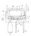
- FIG. 1 is a side view of the electromagnetic relay 1
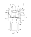
- FIG. 2 is a view taken along arrow A in FIG. 1
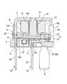
- FIG. 3 is a cross-sectional view taken along line BB in FIG. 2, and FIG. .
- the electromagnetic relay 1 is a device used to turn on and off an inductive load such as a magnet clutch for an air conditioner mounted on a vehicle, for example.
- the electromagnetic relay 1 is disposed between an inner space K formed by a base 2 and a cover 17 attached to the base 2, the base 2 and the coil 4, a movable contact 21, and A contact portion 3 including a fixed contact 22.
- a silver-tin oxide-indium oxide system contact is used for the contact on the anode forming side, and silver is used for the contact on the side forming the cathode.
- -Zinc oxide based contacts are used.
- the cover 17 is formed in a box shape with an opening on the base 2 side, using an insulating resin.
- the opening of the cover 17 is formed so as to correspond to the outer shape of the base 2, and the base 2 is attached so as to close the opening of the cover 17.
- the base 2 and the cover 17 are fixed to each other by fitting or bonding.
- the base 2 is formed in a substantially rectangular flat plate shape with an insulating resin.
- slits 7 and 7 for coil terminals are formed on both sides in the direction orthogonal to the longitudinal direction.
- Each of the coil terminal slits 7 is formed in a substantially rectangular shape in plan view so as to be elongated along the longitudinal direction of the base 2.
- the coil terminals 8 and 8 are inserted into the respective coil terminal slits 7 and 7 thus formed.
- the coil terminal slit 7 is configured such that almost no gap is formed between the coil terminal slit 7 and the coil terminal 8 when the coil terminal 8 is inserted through the coil terminal slit 7. Yes.
- the coil terminal 8 inserted through the coil terminal slit 7 protrudes from one surface of the base 2 (the lower surface in FIGS. 1 to 3).
- the coil 4 is connected to the coil terminal 8, and the coil 4 is energized through the coil terminal 8.
- the base 2 has a movable contact terminal slit 9 formed at the other end in the longitudinal direction (the right end in FIGS. 1 and 4 and the left end in FIG. 3).
- the movable contact terminal slit 9 is formed in a substantially rectangular shape in plan view so as to be elongated along a direction orthogonal to the longitudinal direction of the base 2.
- the movable contact terminal 10 described later is inserted into the movable contact terminal slit 9 formed in this manner. Further, the movable contact terminal slit 9 has almost no gap between the movable contact terminal slit 9 and the movable contact terminal 10 when the movable contact terminal 10 is inserted into the movable contact terminal slit 9. It is configured as follows.
- the base 2 is formed with a fixed contact terminal slit 11 substantially at the center in the longitudinal direction.
- the fixed contact terminal slit 11 is formed in a substantially rectangular shape in plan view so as to be elongated along a direction orthogonal to the longitudinal direction of the base 2.
- a fixed contact terminal 12 (described later) is inserted into the fixed contact terminal slit 11 thus formed. Further, the fixed contact terminal slit 11 has almost no gap between the fixed contact terminal slit 11 and the fixed contact terminal 12 when the fixed contact terminal 12 is inserted into the fixed contact terminal slit 11. It is configured as follows.
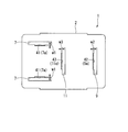
- vent holes 41 to 43 are configured to discharge nitrogen oxides and water vapor generated in the internal space K formed by the base 2 and the cover 17 to the outside when the electromagnetic relay 1 is operated.
- Each of the vent holes 41 to 43 is formed in a substantially rectangular shape in plan view so as to extend along the longitudinal direction of the terminal slits 7, 9, 11 formed respectively.
- the air vent 41 is formed at the inner edge on the opposite side.
- the vent hole 41 is formed in a substantially longitudinal shape in plan view so as to extend along the longitudinal direction of the coil terminal slit 7.
- the movable contact terminal slit 9 is formed with a vent 42 at the inner edge on the inner side in the longitudinal direction of the base 2.
- the vent 42 is formed in a substantially rectangular shape in plan view so as to extend along the longitudinal direction of the movable contact terminal slit 9.
- the fixed contact terminal slit 11 is formed with a vent 43 at the inner edge on the side where the coil terminal slit 7 is formed.
- the vent hole 43 is formed in a substantially rectangular shape in plan view so as to extend along the longitudinal direction of the fixed contact terminal slit 11.
- each of the vent holes 41 to 43 has a width W1 to W3 in a direction perpendicular to the longitudinal direction so that W1 ⁇ 0.15 mm (2) W2 ⁇ 0.15mm (3) W3 ⁇ 0.15mm (4) It is formed to satisfy. Further, the total opening area Aa, which is the sum of the opening areas A (areas of the shaded portions in FIG. 4) of the vents 41 to 43, Aa ⁇ 1.4 mm 2 (5) It is set to satisfy.
- first support column 5 is provided on one end side in the longitudinal direction of the base 2 so as to protrude toward the side opposite to the protruding direction of the terminals 8, 10, 12 (upper side in FIGS. 1 and 3). Further, on the other end side in the longitudinal direction of the base 2, the second support column 6 is provided so as to protrude toward the opposite side to the protruding direction of the terminals 8, 10, 12.
- a yoke 19 having a substantially L-shaped cross section is supported on the first support column 5 and the second support column 6.
- the yoke 19 is configured so that a magnetic path is formed, and is formed by bending a metal plate by pressing.
- the yoke 19 has an upper wall 19a facing the base 2 at a predetermined interval, and a vertical wall that is bent and extended substantially perpendicularly to the upper wall 19a from the end of the upper wall 19a on the second support column 6 side. 19b. Furthermore, the yoke 19 is formed so that the direction in which the upper wall 19a and the vertical wall 19b are continuous becomes longer.
- pillar 5 provided in the base 2 is formed in the cross-sectional substantially C shape.
- an engagement piece 19c that can be inserted inside the first support column 5 is bent and extended at the end of the first support column 5 side. Thereby, one end of the yoke 19 is supported by the first support column 5.
- the second support columns 6 are disposed at both ends in the direction orthogonal to the longitudinal direction of the base 2.
- pillar 6 supports the vertical wall 19b of the yoke 19 so that it may be clamped from the both sides of the direction orthogonal to the longitudinal direction.
- the iron core 18 formed in a rod shape with a magnetic material is fixed to the upper wall 19a of the yoke 19 at the center.
- the iron core 18 is provided vertically from the upper wall 19 a of the yoke 19 toward the base 2.
- the coil 4 is fitted and fixed to the iron core 18 from the outside. That is, the coil 4 is provided in a state of being disposed on the base 2. Further, a flange portion 18a is formed at the tip of the iron core 18, and the coil 4 is prevented from coming off from the iron core 18.
- the coil 4 includes a coil bobbin 14 formed in a cylindrical shape from an insulating resin, and a coil wire 15 wound around the coil bobbin 14.
- the coil wire 15 is wound in a clockwise direction when viewed from the upper wall 19 a side of the yoke 19 in the iron core 18.
- the winding start end and the winding end end of the coil wire 15 are respectively connected to the coil terminal 8 by fusing.
- a resistor 16 is provided between the coil terminals 8 and 8 so as to straddle both.
- the resistor 16 is a member for absorbing the counter electromotive voltage of the coil 4.
- a movable contact spring 20 is attached to the vertical wall 19 b of the yoke 19.
- the movable contact spring 20 is a member for supporting the movable contact 21 constituting one of the contact portions 3.
- the movable contact spring 20 is a conductive leaf spring material and has a substantially L-shaped cross section.
- the movable contact spring 20 is bent and extended so as to be interposed between the base 2 and the coil 4 from the base 2 side end of the mounting seat 31 and the mounting seat 31 attached to the vertical wall 19b of the yoke 19. And an operating piece 32.
- the mounting seat 31 is formed in a large portion at the center of the vertical wall 19b of the yoke 19 and is formed in a substantially U shape in plan view. That is, the mounting seat 31 extends in the longitudinal direction and is opposed to the pair of arm portions 31a and 31a facing each other in the direction orthogonal to the longitudinal direction, and the ends of the arm portions 31a and 31a on the opposite side to the base 2.
- the connecting portion 31b extends so as to straddle and connects the arm portions 31a and 31a.
- welding points P1 are respectively set at both ends forming connection portions with the arm portions 31a and 31a. By performing spot welding or the like on these welding points P1, the movable contact spring 20 is attached to the vertical wall 19b of the yoke 19.
- the operating piece 32 is bent from the tips of the arm portions 31a and 31a and extends from the tips of the support pieces 32a and 32a.
- the plate width is such that the support pieces 32a and 32a can be connected.
- the main body 32b set to the above.
- the movable contact 21 is attached to the front-end
- the iron piece 25 is provided in the surface at the side of the coil 4 of the main-body part 32b.
- the operating piece 32 is provided such that the iron piece 25 is separated from the flange portion 18 a of the iron core 18. When the iron core 18 is excited by energizing the coil wire 15, the operating piece 32 is elastically deformed, and the iron piece 25 is attracted to the iron core 18.
- the movable contact terminal 10 is attached to the vertical wall 19b of the yoke 19.
- the movable contact terminal 10 is integrally formed with a mounting seat 33 attached to the vertical wall 19b and an external connection portion 34 extending from the mounting seat 33 toward the opposite side of the yoke 19 with the base 2 interposed therebetween. It is a member made.
- the mounting seat 33 of the movable contact terminal 10 is formed in a substantially L shape in plan view. That is, the mounting seat 33 is one of the two arm portions 31a, 31a of the mounting seat 31 constituting the operating piece 32, that is, the arm portion 31a located on the right side in FIG. 2 and the longitudinal length of the vertical wall 19b. It has the 1st arm part 33a which opposes in the direction orthogonal to a direction. Moreover, the 1st arm part 33a is long formed along the longitudinal direction of the vertical wall 19b.
- a second arm portion 33b that is bent and extended so as to be substantially orthogonal to the first arm portion 33a is integrally formed at the tip of the first arm portion 33a.
- the welding point P2 is set to the 1st arm part 33a at the base end on the opposite side to the 2nd arm part 33b.
- the movable contact terminal 10 is attached to the vertical wall 19b of the yoke 19 by performing spot welding or the like on the welding point P2.
- the external connection portion 34 is connected to the tip of the second arm portion 33b.
- the external connection portion 34 is inserted into the movable contact terminal slit 9 formed in the base 2. Thereby, the external connection part 34 protrudes from the surface on the opposite side to the coil 4 of the base 2, and is electrically connected to load (not shown, for example, magnet clutch for air conditioners).
- the fixed contact terminal 12 that is electrically connected to the load (not shown) together with the movable contact terminal 10 has an external connection portion 35 that is inserted into the slit 11 for the fixed contact terminal.
- the base end of the external connection portion 35 protrudes toward the coil 4 side of the base 2, and the internal contact portion 36 is bent and extended toward the movable contact 21 side at the protruding base end.
- the tip of the internal contact portion 36 is interposed between the movable contact 21 and the coil 4.
- the fixed contact 22 is attached to the tip of the internal contact portion 36. Thereby, the movable contact 21 and the fixed contact 22 are arranged to face each other with a predetermined interval.
- the movable contact spring 20 is elastically deformed, the iron piece 25 is attracted to the iron core 18, and the movable contact 21 comes into contact with the fixed contact 22 (contact ON). Then, the movable contact spring 20 and the fixed contact terminal 12 are electrically connected via the movable contact 21 and the fixed contact 22. Since the movable contact spring 20 is electrically connected to the movable contact terminal 10 via the vertical wall 19b of the yoke 19, the movable contact terminal 10 and the fixed contact terminal 12 are electrically connected. Thereby, the electric current of an external power supply (not shown) is supplied to a load (not shown, for example, a magnet clutch for an air conditioner).
- the iron core 18 is demagnetized.
- the iron piece 25 is separated from the iron core 18 by the elastic action of the movable contact spring 20 (contact off). Accordingly, the movable contact 21 is separated from the fixed contact 22.
- the movable contact terminal 10 and the fixed contact terminal 12 are electrically disconnected, and the supply of current to a load (not shown) is stopped.
- an arc discharge may occur between the fixed contact 22 and the movable contact 21 as the contact is turned on / off.
- nitrogen oxides are generated in the internal space K formed by the base 2 and the cover 17.
- moisture absorbed by the resin coil bobbin 14 is generated in the internal space K as water vapor.
- the vent holes 41 to 43 are formed in the base 2, nitrogen oxides and water vapor generated in the internal space K are discharged to the outside through the vent holes 41 to 43.
- the vent holes 41 to 43 are set so that the total opening area Aa obtained by adding up these opening areas (areas of the shaded portions in FIG. 4) satisfies the formula (5). Product and water vapor are discharged.
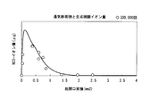
- the vertical axis represents the amount of nitrate ion produced [ ⁇ g] generated by the reaction of nitrogen oxides and water vapor in the internal space K of the electromagnetic relay 1, and the horizontal axis represents the ventilation ports 41 to 43.
- the total opening area Aa of the vent holes 41 to 43 is 1.4 mm 2 when the vertical axis indicates the concentration [ppm] of nitrogen oxide (NOx) and the horizontal axis indicates the elapsed time [minute].
- vent holes 41 to 43 are formed in the base 2, ants may enter from the vent holes 41 to 43.
- the widths W1 to W3 in the direction perpendicular to the longitudinal direction of the vent holes 41 to 43 are set so as to satisfy the expressions (2) to (4), respectively.
- Various ants can be prevented from entering.
- the smallest width of the ant's head which is said to be the smallest in the world, is larger than 0.15 mm. It was issued.
- the vent holes 41 to 43 are formed in a substantially rectangular shape in plan view, and the widths W1 to W3 in the direction orthogonal to the longitudinal direction are set so as to satisfy the expressions (2) to (4). Has been. Therefore, it is possible to reliably prevent the ants from entering the internal space K through the vent holes 41 to 43.
- vent holes 41 to 43 are formed in the terminal slits 7, 9, and 11, respectively. That is, since a plurality of (two or more) vent holes 41 to 43 are formed, nitrogen oxides and water vapor can be discharged reliably and promptly. Further, vent holes 41 to 43 are formed at the inner edges of the terminal slits 7, 9, 11 formed in the base 2. That is, the respective vent holes 41 to 43 are formed in communication with the respective terminal slits 7, 9, 11. Therefore, the manufacturing cost of the base 2 can be reduced as compared with the case where the vent holes 41 to 43 are formed so as to be separated from the terminal slits 7, 9 and 11.
- the terminal slits 7, 9, 11 of the base 2 are formed in a substantially rectangular shape in plan view so as to be long along the longitudinal direction of the base 2, and in the longitudinal direction of these terminal slits 7, 9, 11.
- the widths W1 to W3 in the orthogonal direction are set so as to satisfy the expressions (2) to (4), respectively. Therefore, the vent holes 41 to 43 have a simple shape, and ants can be prevented from entering the internal space K from the vent holes 41 to 43.
- the present invention is not limited to the first embodiment described above, and includes a configuration in which various modifications are added to the first embodiment described above without departing from the spirit of the present invention.
- the terminal slits 7, 9, 11 of the base 2 are formed in a substantially rectangular shape in plan view so as to be long along the longitudinal direction of the base 2, and these terminal slits 7 , 9, and 11 have been described in the case where the widths W1 to W3 in the direction orthogonal to the longitudinal direction are set so as to satisfy the expressions (2) to (4), respectively.
- the configuration is not limited to the above, and each of the terminal slits 7, 9, and 11 may be formed so that a sphere having a diameter of 0.15 mm cannot pass through.
- each of the terminal slits 7, 9, and 11 is formed in a substantially rectangular shape in plan view, and the widths W1 to W3 in the direction orthogonal to the respective longitudinal directions satisfy the expressions (2) to (4), respectively. In this way, a sphere whose diameter is set to 0.15 mm cannot be passed through the terminal slits 7, 9, 11.
- vent holes 41 to 43 are formed in communication with the inner edges of the terminal slits 7, 9, 11 formed in the base 2 .
- the present invention is not limited to the above configuration, and vent holes 41 to 43 may be formed at positions separated from the terminal slits 7, 9, 11 of the base 2. Further, it is not necessary to form the vent holes 41 to 43 in the terminal slits 7, 9, and 11, and it is sufficient that at least one vent hole is formed in the base 2.
- the air inlets 41 to 43 are not formed on the inner edges of the terminal slits 7, 9, 11 of the base 2, but the coil terminals 8 inserted into the terminal slits 7, 9, 11 and the movable contacts are formed.
- the vent holes 141 to 143 may be formed in the base 2.
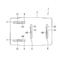
- FIG. 7 is a plan view of the base 2 showing a modification of the electromagnetic relay 1 according to the first embodiment of the present invention.
- the same reference numerals are given to the same forms as those in the first embodiment, and the description thereof is omitted.
- a coil terminal 8, a movable contact terminal 10, and a fixed contact terminal 12 are inserted through the terminal slits 7, 9, 11 of the base 2, respectively.
- a recess 51 is formed along the insertion direction of the coil terminal 8 at a position corresponding to the coil terminal slit 7 of the coil terminal 8.
- An opening surrounded by the recess 51 and the inner edge of the coil terminal slit 7 functions as a vent hole 141. That is, the vent 141 is formed in the base 2.
- a concave portion 52 is formed in the external connection portion 34 of the movable contact terminal 10 at a position corresponding to the movable contact terminal slit 9 along the insertion direction of the external connection portion 34.
- An opening surrounded by the recess 52 and the inner edge of the movable contact terminal slit 9 functions as a vent 142. That is, the vent hole 142 is formed in the base 2.
- a concave portion 53 is formed in the external connection portion 35 of the fixed contact terminal 12 at a position corresponding to the fixed contact terminal slit 11 along the insertion direction of the external connection portion 35.
- An opening surrounded by the recess 53 and the inner edge of the movable contact terminal slit 9 functions as a vent 143. That is, the vent hole 143 is formed in the base 2. Even if it is a case where it is comprised as mentioned above, there can exist an effect similar to the above-mentioned 1st embodiment.
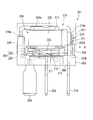
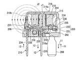
- FIG. 8 is a side view of the electromagnetic relay 201
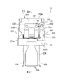
- FIG. 9 is a view taken along arrow A in FIG. 8
- FIG. 10 is a cross-sectional view taken along line BB in FIG.
- the electromagnetic relay 201 is a device used to turn on / off a lamp (Lamp) mounted on a vehicle, for example.
- the electromagnetic relay 201 includes a coil 204 on a base 202.
- a contact portion 203 including a movable contact 221 and a fixed contact 222 is disposed between the base 202 and the coil 204.
- the contact portions 203 and the coil 204 are covered with a cover 217.
- the base 202 is formed in a substantially rectangular flat plate shape with an insulating resin.
- coil terminal slits 207 and 207 are formed on both sides in the short direction.
- the coil terminals 208 and 208 are inserted into the coil terminal slits 207 and 207, respectively, and the coil terminals 208 and 208 protrude from one surface of the base 202 (the lower surface in FIGS. 8 to 10).
- a coil 204 is connected to the coil terminal 208, and the coil 204 is energized via the coil terminal 208.
- first support column 205 is provided on one end side in the longitudinal direction of the base 202 so as to protrude toward the opposite side (upper side in FIGS. 8 and 10) from the protruding direction of the terminals 208, 210, and 212.
- second support column 206 is provided on the other end side in the longitudinal direction of the base 202 so as to protrude toward the opposite side to the protruding direction of the terminals 208, 210, and 212.
- a yoke 219 having a substantially L-shaped cross section is supported on the first support column 205 and the second support column 206.
- the yoke 219 is configured to form a magnetic path, and is formed by bending a metal plate by pressing.
- the yoke 219 has an upper wall 219a facing the base 202 with a predetermined interval, and a vertical wall extending from the end of the upper wall 219a on the second support column 206 side by being bent substantially perpendicularly to the upper wall 219a. 219b. Further, the yoke 219 is formed so that the direction in which the upper wall 219a and the vertical wall 219b are continuous becomes longer.
- the first support column 205 provided so as to stand up with respect to the base 202 has a substantially C-shaped cross section.
- an engagement piece 219c that can be inserted inside the first support column 205 is bent and extended at the end of the first support column 205.
- one end of the yoke 219 is supported by the first support column 205.
- the second support columns 206 are disposed at both ends of the base 202 in the short direction. The second support column 206 supports the vertical wall 219b of the yoke 219 so as to be sandwiched from both sides in the short direction.
- An iron core 218 formed in a bar shape with a magnetic material is fixed to the upper wall 219a of the yoke 219.
- the iron core 218 is provided vertically from the upper wall 219 a of the yoke 219 toward the base 202.
- a coil 204 is fitted and fixed to the iron core 218 from the outside. That is, the coil 204 is provided in a state of being disposed on the base 202. Further, a flange portion 218a is formed at the tip of the iron core 218, and the coil 204 is prevented from coming off from the iron core 218.
- the coil 204 includes a cylindrical coil bobbin 214 and a coil wire 215 wound around the coil bobbin 214.
- the coil wire 215 is wound in a clockwise direction when viewed from the upper wall 219a side of the yoke 219 in the iron core 218.
- the winding start end and winding end of the coil wire 215 are connected to the coil terminal 208 by fusing.
- a register 216 is provided between the coil terminals 208 and 208 so as to straddle both.
- the resistor 216 is a member for absorbing the counter electromotive voltage of the coil 204.
- a movable contact spring 220 is attached to the vertical wall 219b of the yoke 219.
- the movable contact spring 220 is a member for supporting the movable contact 221 that constitutes one of the contact portions 203.
- the movable contact spring 220 is a conductive leaf spring material and has a substantially L-shaped cross section.
- the movable contact spring 220 is bent and extended from a mounting seat 231 attached to the vertical wall 219b of the yoke 219 and the base 202 side end of the mounting seat 231 so as to be interposed between the base 202 and the coil 204. And an operating piece 232.
- the mounting seat 231 is formed in the most part of the center of the vertical wall 219b of the yoke 219, and is formed in a substantially U shape in plan view. In other words, the mounting seat 231 extends in the longitudinal direction and straddles a pair of arm portions 231a and 231a facing each other in the short-side direction and ends opposite to the base 202 of the arm portions 231a and 231a.
- the connecting portion 231b extends and connects both arm portions 231a and 231a.
- connection points P201 for caulking or welding are set at both ends forming connection portions with the arm portions 231a and 231a, respectively. By performing spot welding or the like on these connection points P201, the movable contact spring 220 is attached to the vertical wall 219b of the yoke 219.
- the actuating piece 232 is bent from the tips of the arm portions 231a and 231a and extends from the tips of the support pieces 232a and 232a. It is comprised by the main-body part 232b set to. And the movable contact 221 is attached to the front-end
- the movable contact terminal 210 is attached to the vertical wall 219b of the yoke 219.
- the movable contact terminal 210 is integrally formed with a mounting seat 233 attached to the vertical wall 219b and an external connection portion 234 extending from the mounting seat 233 toward the opposite side of the yoke 219 across the base 202. It is a member made.
- the mounting seat 233 of the movable contact terminal 210 is formed in a substantially L shape in plan view. That is, the mounting seat 233 is one of the two arm portions 231a and 231a of the mounting seat 231 constituting the operating piece 232, that is, the short of the arm portion 231a and the vertical wall 219b located on the right side in FIG. It has the 1st arm part 133a which opposes by a hand direction.
- the first arm portion 233a is formed long along the longitudinal direction of the vertical wall 219b.
- a second arm portion 233b that is bent and extended so as to be substantially orthogonal to the first arm portion 233a is integrally formed at the tip of the first arm portion 233a.
- a connection point P202 for caulking or welding is set at the base end opposite to the second arm portion 233b.
- the movable contact terminal 210 is attached to the vertical wall 219b of the yoke 219.
- an external connection portion 234 is connected to the tip of the second arm portion 233b.
- the base 202 has a movable contact terminal slit 209 formed on the other end in the longitudinal direction (the right end in FIG. 8 and the left end in FIG. 10).
- the external contact portion 234 of the movable contact terminal 210 is inserted through the movable contact terminal slit 209. Thereby, the external connection part 234 of the movable contact terminal 210 protrudes from the surface of the base 202 opposite to the coil 204.
- a fixed contact terminal slit 211 is formed substantially at the center in the longitudinal direction of the base 202.
- the fixed contact terminal 212 is inserted into the fixed contact terminal slit 211.
- the fixed contact terminal 212 has an external connection portion 235 inserted through the fixed contact terminal slit 211.
- the base end of the external connection portion 235 protrudes toward the coil 204 side of the base 202, and the internal contact portion 236 is bent and extended toward the movable contact 221 side at the protruding base end.
- the tip of the internal contact portion 236 is interposed between the movable contact 221 and the coil 204.
- a fixed contact 222 is attached to the tip of the internal contact portion 236. Thereby, the movable contact 221 and the fixed contact 222 are arranged to face each other with a predetermined interval.
- FIGS. 9, 10, 11A, and 11B are explanatory diagrams of the operation of the electromagnetic relay 201 and correspond to FIG.
- FIG. 11A shows a state where the coil wire 215 of the coil 204 is not energized.
- FIG. 11B shows a state where the coil wire 215 of the coil 204 is energized.
- the movable contact 221 and the fixed contact 222 constituting the contact portion 203 are separated from each other.
- the current supplied to the coil terminal 208 is referred to as a primary current
- the current flows to the coil wire 215 via the coil terminal 208,
- the iron core 218 is excited.
- the coil wire 215 is wound in a clockwise direction when viewed from the upper wall 219a side of the yoke 219 in the iron core 218. Therefore, the direction of the magnetic field J1 formed by energizing the coil wire 215 is the direction from the upper wall 219a of the yoke 219 toward the flange portion 218a of the iron core 218.
- the current I202 of the external power supply (not shown) is supplied to the load (not shown, for example, a lamp).
- the current supplied to the movable contact terminal 210 and the fixed contact terminal 212 is referred to as a secondary current.
- FIGS. 9 and 11B As shown in FIGS. 9 and 11B, when the movable contact terminal 210 and the fixed contact terminal 212 are electrically connected, a current flows from the movable contact terminal 210 to the fixed contact terminal 212 via the movable contact spring 220. . At this time, the movable contact terminal 210 and the movable contact spring 220 are disposed to face each other in the short direction on the vertical wall 219b of the yoke 219. Therefore, in FIG. 9, a current flows from right to left, that is, from the connection point P202 to the connection point P201 (see arrow Y1 in FIG. 9). In FIG. 11B, a current flows on the vertical wall 219b of the yoke 219 from the front side to the back side.
- the magnetic field J2 in the clockwise direction in FIG. 11B is generated on the vertical wall 219b of the yoke 219.
- the direction of the magnetic field J2 is the same as the direction of the magnetic field J1 formed when the coil wire 215 is energized on the iron core 218. Therefore, the magnetic field J2 is superimposed on this magnetic field J1. For this reason, the attractive force with respect to the iron piece 225 of the excited iron core 218 increases.
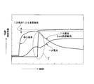
- the vertical axis indicates the primary current, the secondary current, and the magnetic flux density of the magnetic field J1 generated in the iron core 218, and the horizontal axis indicates time, and the changes in the primary current, the secondary current, and the magnetic flux.
- the movable contact 221 contacts the fixed contact 222, and a secondary current is supplied to the movable contact terminal 210 and the fixed contact terminal 212.
- this secondary current generates a magnetic field J2 on the vertical wall 219b of the yoke 219, and this magnetic field J2 is superimposed on the magnetic field J1.
- the primary current is reduced by superimposing the magnetic field J2 on the magnetic field J1 (see part C in FIG. 12).
- the magnetic flux density of the magnetic field generated in the iron core 218 becomes a magnitude obtained by adding the magnetic flux density of the magnetic field J2 to the magnetic flux density of the magnetic field J1.
- the magnetic force generated in the iron core 218 increases as the magnetic field J2 is superimposed, and the attractive force with respect to the iron piece 225 increases. Therefore, the iron piece 225 is reliably adsorbed to the iron core 218, and the movable contact 221 contacts the fixed contact 222 with certainty.
- the iron core 218 is demagnetized. Then, the iron piece 225 is separated from the iron core 218 by the elastic action of the movable contact spring 220. Accordingly, the movable contact 221 is separated from the fixed contact 222. Thereby, the movable contact terminal 210 and the fixed contact terminal 212 are electrically disconnected, and the supply of the secondary current is stopped.
- the mounting seat 231 of the movable contact spring 220 is attached to the vertical wall 219b of the yoke 219, and the arm portion 231a of the mounting seat 231 and the vertical wall 219b are arranged in the short direction.
- a magnetic field J2 generated in the yoke 219 due to the secondary current flowing between the mounting seats 231 and 233 is generated in the coil 204 by the primary current. It can be superimposed on the magnetic field J1.
- produces in the iron core 218 increases, and the attraction
- the mounting seat 231 of the movable contact spring 220 is formed in most of the longitudinal direction of the vertical wall 219b of the yoke 219, whereby the rigidity of the movable contact spring 220 can be increased. That is, the mounting space of the mounting seat 231 of the movable contact spring 220 that repeats elastic deformation is secured larger than the movable contact terminal 210 that does not move after being mounted on the yoke 219, thereby increasing the rigidity of the movable contact spring 220. Can be increased. For this reason, damage due to metal fatigue of the movable contact spring 220 can be reliably prevented, and the life of the electromagnetic relay 201 can be extended.
- the present invention is not limited to the second embodiment described above, and includes various modifications made to the second embodiment described above without departing from the spirit of the present invention.
- the mounting seat 231 of the movable contact spring 220 is attached to the vertical wall 219b of the yoke 219, and the arm portion 231a of the mounting seat 231 is opposed to the vertical wall 219b in the short direction.
- the case where the mounting seat 233 of the movable contact terminal 210 is mounted has been described.
- the present invention is not limited to the above configuration, and the mounting position of the mounting seat 231 of the movable contact spring 220 and the mounting seat 233 of the movable contact terminal 210 with respect to the yoke 219 is such that the secondary current flows between the mounting seats 231 and 233. Any position may be used as long as the magnetic field J2 generated in 219 is superimposed on the magnetic field J1 generated in the coil 204.
- the direction of the current flowing in the coil wire 215 is opposite to the direction in the second embodiment described above, or the winding direction of the coil wire 215 around the coil bobbin 214 is opposite to the direction in the second embodiment described above.
- the case where the direction of the magnetic field J1 generated in the coil 204 is the direction from the flange portion 218a of the iron core 218 toward the upper wall 219a of the yoke 219 will be described.
- the direction of the magnetic field J1 is a counterclockwise direction that is opposite to the direction in the second embodiment described above.
- the mounting seat 233 of the movable contact terminal 210 faces the arm portion 231a located on the left side in FIG. 9 among the two arm portions 231a and 231a constituting the mounting seat 231 of the movable contact spring 220. Placed in.
- the mounting seat 231 of the movable contact spring 220 is formed in the most part of the center of the vertical wall 219b of the yoke 219 and is formed in a substantially U shape in plan view. explained.
- the configuration is not limited to this, and it is only necessary to form the magnetic field J2 in a predetermined direction.
- the magnetic field J2 changes from the connection point P202 set on the mounting seat 233 of the movable contact terminal 210 to the connection point P201 set on the mounting seat 231 of the movable contact spring 220 on the vertical wall 219b of the yoke 219. It is formed by the current flowing in the direction. For this reason, if the distance between these connection points P201 and P202 can be secured long, the magnetic flux density of the magnetic field J2 can be increased accordingly. Therefore, it is desirable that the mounting seat 231 of the movable contact spring 220 is formed so as to ensure the distance between the connection points P201 and P202 as long as possible while ensuring this rigidity.
- the mounting seat 233 of the movable contact terminal 210 may be disposed inside the mounting seat 231 of the movable contact spring 220. This will be described in more detail with reference to FIG.
- FIG. 13 is a front view showing a modification of the electromagnetic relay 101 according to the second embodiment of the present invention, and corresponds to FIG.
- the same reference numerals are given to the same forms as those of the second embodiment described above, and the description thereof is omitted.
- the mounting seat 331 of the movable contact spring 220 is formed in a substantially U shape in plan view so as to be along the outer peripheral portion of the vertical wall 219b of the yoke 219.
- the mounting seat 331 extends in the longitudinal direction, and a pair of arm portions 331a and 331a disposed on both sides in the short side direction of the vertical wall 219b, and ends opposite to the base 202 of the arm portions 331a and 331a. And a connecting portion 331b that connects both arm portions 331a and 331a.
- connection point P201 is set to each arm part 331a and 331a at the connection part 331b side, respectively. By performing spot welding or the like on these connection points P201, the movable contact spring 220 is attached to the vertical wall 219b of the yoke 219.
- the mounting seat 333 of the movable contact terminal 210 is formed in a strip shape along the longitudinal direction of the vertical wall 219b of the yoke 219, and is disposed inside the mounting seat 331 of the movable contact spring 220.
- a connection point P202 is set at the tip of the mounting seat 333. By performing spot welding or the like on the connection point P202, the movable contact terminal 210 is attached to the vertical wall 219b of the yoke 219.
- the mounting seat 333 of the movable contact terminal 210 is not positioned at the approximate center between the pair of arm portions 331a and 331a constituting the mounting seat 331 of the movable contact spring 220, that is, closer to one arm portion 331a, that is, In FIG. 13, it is located slightly to the right of the center. Therefore, compared with the distance L1 between one arm portion 331a, that is, the right arm portion 331a in FIG. 13 and the mounting seat 333 of the movable contact terminal 210, the other arm portion 331a, that is, in FIG. The distance L2 between the left arm portion 331a is set long.
- the primary contact current is supplied to the coil 204, whereby the movable contact terminal 210 and the fixed contact terminal 212 are electrically connected. Then, current flows between the arm portions 331 a and 331 a of the movable contact spring 220 and the mounting seat 333 of the movable contact terminal 210 on the vertical wall 219 b of the yoke 219. More specifically, a current flows from the mounting seat 333 toward one arm portion 331a, that is, in the right direction in FIG. 13 (see arrow Y2 in FIG. 13). Further, a current flows from the mounting seat 333 toward the other arm portion 3231a, that is, in the left direction in FIG. 13 (see arrow Y3 in FIG. 13).
- the direction of the current flowing from the mounting seat 333 toward the one arm portion 331a and the direction of the current flowing from the mounting seat 333 toward the other arm portion 331a are opposite to each other. Form. For this reason, the magnetic fields formed by both cancel each other.
- the distance L2 between the mounting seat 333 and the other arm portion 331a is set longer than the distance L1 between the mounting seat 333 and the one arm portion 331a. Therefore, the magnetic field formed by the current (see arrow Y3 in FIG. 13) flowing from the mounting seat 333 toward the other arm portion 331a remains. This magnetic field is in the same direction as the magnetic field J2 in the second embodiment described above. For this reason, it is superimposed on the magnetic field J1 generated in the coil 204, and the attractive force of the iron core 218 to the iron piece 225 increases.
- nitrogen oxide and water vapor generated in the internal space can be discharged to the outside through the vent, so that it is not necessary to maintain the airtightness of the internal space with high accuracy.
- the life of the electromagnetic relay can be extended at low cost.
Landscapes
- Physics & Mathematics (AREA)
- Electromagnetism (AREA)
- Contacts (AREA)
- Switch Cases, Indication, And Locking (AREA)
Abstract
Description
本願は、2011年6月28日に、日本に出願された特願2011-142815号に基づき優先権を主張し、その内容をここに援用する。
上記の構成において、コイルの励磁及び消磁に基づいて、固定接点に対して可動接点が当接(オン)したり離反(オフ)したりする。この接点のオン・オフに伴って、不図示の外部電源の電流が負荷へ供給されたり、遮断されたりする(例えば、特許文献1参照)。
しかしながら、気密性を維持するためには、ベース、及びカバーに、例えば酸素透過性の低いLCP等の高価な樹脂を採用したり、ベースの可動接点端子、及び固定接点端子周りのシール性を維持することができる接着技術を採用したりする必要がある。このため、電磁継電器の製造コストが増加する可能性がある。
また、僅かな気密漏れが生じると、カバー外部から酸素や水分が密閉空間内に供給され、硝酸生成量が増加する。このため、電磁継電器の寿命が縮まる可能性がある。
また、端子用スリットと共に容易に形成することができ、さらに製造コストを減少させることができる。
A≧1.4mm2・・・(1)
を満たすように設定することにより、確実に窒素酸化物、及び水蒸気を排出することができる。
ここで、蟻の侵入を防止するために、世界最小の頭部を持つ蟻を調査した結果、世界最小といわれるアリの頭部の最小幅が0.15mmよりも大きいことが見出された。このため、ベースに形成される通気口を、直径が0.15mmに設定されている球体が通過できないように形成することにより、内部空間へのさまざまな蟻の侵入を防止できる。
また、端子用スリットと共に容易に形成することができ、さらに製造コストを減少させることができる。
(電磁継電器)
次に、本発明の第一実施形態を図面に基づいて説明する。
図1は、電磁継電器1の側面図、図2は、図1のA矢視図、図3は、図2のB-B線に沿う断面図、図4は、ベース2の平面図である。
図1~図4に示すように、電磁継電器1は、例えば車両に搭載されているエアコン用マグネットクラッチ等の誘導性負荷のON、OFFを行うために用いられる装置である。電磁継電器1は、ベース2と、このベース2に取付けられるカバー17とにより形成される内部空間Kに設けられたコイル4と、ベース2とコイル4との間に配置され、可動接点21、及び固定接点22から構成される接点部3と、を備える。
可動接点21、及び固定接点22の接点材料としては、例えば、陽極を形成する側の接点には、銀-酸化スズ-酸化インジウム系接点が使用され、陰極を形成する側の接点には、銀-酸化亜鉛系接点が使用される。
ベース2は、絶縁性を有する樹脂により、略長方形の平板形状に形成されている。ベース2の長手方向一端側(図1、図4における左端、図3における右端)には、長手方向に直交する方向の両側にそれぞれコイル端子用スリット7,7が形成されている。各コイル端子用スリット7は、ベース2の長手方向に沿って長くなるように平面視略長方形状に形成されている。このように形成された各コイル端子用スリット7,7に、それぞれコイル端子8,8が挿通される。
さらに、可動接点端子用スリット9は、この可動接点端子用スリット9に可動接点端子10が挿通された状態において、これら可動接点端子用スリット9と可動接点端子10との間に殆ど隙間が形成されないように構成されている。
さらに、固定接点端子用スリット11は、この固定接点端子用スリット11に固定接点端子12が挿通された状態において、これら固定接点端子用スリット11と固定接点端子12との間に殆ど隙間が形成されないように構成されている。
また、可動接点端子用スリット9には、ベース2の長手方向内側の内側縁に、通気口42が形成されている。通気口42は、可動接点端子用スリット9の長手方向に沿うように、平面視略長方形状に形成されている。
さらに、固定接点端子用スリット11には、コイル端子用スリット7が形成されている側の内側縁に、通気口43が形成されている。通気口43は、固定接点端子用スリット11の長手方向に沿うように、平面視略長方形状に形成されている。
W1<0.15mm・・・(2)
W2<0.15mm・・・(3)
W3<0.15mm・・・(4)
を満たすように、形成されている。
さらに、各通気口41~43の各開口面積A(図4における網掛け部の面積)を合計した総開口面積Aaは、
Aa≧1.4mm2・・・(5)
を満たすように設定されている。
一方、第2支柱6はベース2の長手方向に直交する方向の両端にそれぞれ配置されている。第2支柱6は、ヨーク19の縦壁19bを、その長手方向に直交する方向の両側から挟持するように支持する。
連結部31bには、各アーム部31a,31aとの接続部分を形成する両端に、それぞれ溶接ポイントP1が設定されている。これら溶接ポイントP1にスポット溶接等を施すことにより、ヨーク19の縦壁19bに、可動接点バネ20が取付けられる。
そして、第1アーム部33aには、第2アーム部33bとは反対側の基端に、溶接ポイントP2が設定されている。この溶接ポイントP2にスポット溶接等を施すことにより、ヨーク19の縦壁19bに可動接点端子10が取付けられる。また、第2アーム部33bの先端に、外部接続部34が接続されている。
この外部接続部34がベース2に形成されている可動接点端子用スリット9に挿通されている。これにより、外部接続部34は、ベース2のコイル4とは反対側の面から突出し、負荷(不図示、例えばエアコン用マグネットクラッチ)に電気的に接続される。
次に、図1、図4~図6に基づいて、電磁継電器1の作用について説明する。
図1、図4に示すように、コイル4のコイル線材15に通電を行っていない状態では、接点部3を構成している可動接点21と固定接点22とが離反している。
一方、コイル端子8を介してコイル線材15が通電されると、鉄心18が励磁される。
鉄心18が励磁されると、可動接点バネ20に設けられている鉄片25に、鉄心18側に向かう吸引力が作用する。
可動接点バネ20は、ヨーク19の縦壁19bを介して可動接点端子10と電気的に接続されているので、可動接点端子10と固定接点端子12とが電気的に接続される。これにより、外部電源(不図示)の電流が負荷(不図示、例えばエアコン用マグネットクラッチ)に供給される。
ここで、通気口41~43は、これらの開口面積(図4における網掛け部の面積)を合計した総開口面積Aaが式(5)を満たすように設定されているので、確実に窒素酸化物、及び水蒸気が排出される。
図5は、縦軸が、電磁継電器1の内部空間K内において窒素酸化物と水蒸気との反応により生成される硝酸イオンの生成量[μg]を示し、横軸が、通気口41~43の総開口面積[mm2]としたときの硝酸イオンの生成量の変化を示すグラフである。図6は、縦軸が窒素酸化物(NOx)の濃度[ppm]を示し、横軸が経過時間[分]を示すときの、通気口41~43の総開口面積Aaが1.4mm2である場合の窒素酸化物の濃度の変化を示すグラフである。
これは、図6に示すように、通気口41~43の総開口面積Aaが1.4mm2である場合、電磁継電器1の内部空間K内で発生した窒素酸化物が通気口41~43を介して速やかに排出され、窒素酸化物が発生してから約3分後には、内部空間K内にほとんど窒素酸化物が残留していないからである。
したがって、上述の第一実施形態によれば、ベース2とカバー17とにより形成される内部空間Kにおいて、窒素酸化物と水蒸気とが反応し硝酸が生成されることを確実に抑制できる。また、内部空間Kの気密性を高精度に維持する必要がなく、通気口41~43を形成するだけで安価に電磁継電器1の延命化を図ることができる。
また、通気口41~43を介して内部空間Kへさまざまな蟻が侵入することを防止でき、この蟻の侵入による電磁継電器1の損傷を防止できる。よって、電磁継電器1の延命化を図ることができる。
そして、ベース2に形成されている各端子用スリット7,9,11の内側縁に、通気口41~43が形成されている。すなわち、各端子用スリット7,9,11に、それぞれの通気口41~43が連通して形成されている。そのため、各端子用スリット7,9,11と離間するように通気口41~43が形成される場合と比較してベース2の製造コストを低減することができる。
例えば、上述の第一実施形態では、ベース2の各端子用スリット7,9,11は、ベース2の長手方向に沿って長くなるように平面視略長方形状に形成され、これら端子用スリット7,9,11の長手方向に直交する方向の幅W1~W3が、それぞれ式(2)~式(4)を満たすように設定されている場合について説明した。しかしながら、上記の構成に限られず、各端子用スリット7,9,11は、直径が0.15mmに設定されている球体が通過することができないように形成されていればよい。
ここで、各端子用スリット7,9,11を平面視略長方形状に形成し、各々の長手方向に直交する方向の幅W1~W3を、それぞれ式(2)~式(4)を満たすように形成することで、各端子用スリット7,9,11に、直径が0.15mmに設定されている球体を通過させることはできない。
より具体的に、図7に基づいて、本発明の第一実施形態に係る通気口41~43の変形例について説明する。
図7は、本発明の第一実施形態に係る電磁継電器1の変形例を示すベース2の平面図である。尚、以下の説明において、上述の第一実施形態と同一形態については、同一符号を付して説明を省略する。
同図に示すように、ベース2の各端子用スリット7,9,11には、それぞれコイル端子8、可動接点端子10、及び固定接点端子12が挿通されている。
また、可動接点端子10の外部接続部34には、可動接点端子用スリット9に対応する位置に、外部接続部34の挿通方向に沿って凹部52が形成されている。そして、これら凹部52と可動接点端子用スリット9の内側縁とによって囲まれた開口部が、通気口142として機能する。つまり、ベース2に、通気口142が形成される。
上記のように構成した場合であっても、上述の第一実施形態と同様の効果を奏することができる。
次に、本発明の第二実施形態を図面に基づいて説明する。
図8は、電磁継電器201の側面図、図9は、図8のA矢視図、図10は、図9のB-B線に沿う断面図である。
図8~図10に示すように、電磁継電器201は、例えば車両に搭載されているランプ(Lamp)の点灯・消灯を行うために用いられる装置である。電磁継電器201は、ベース202上に、コイル204を備える。そして、電磁継電器201には、これらベース202とコイル204との間に、可動接点221、及び固定接点222から構成される接点部203が配置されている。そして、これら接点部203とコイル204とがカバー217で覆われている。
一方、第2支柱206はベース202の短手方向両端にそれぞれ配置されている。第2支柱206は、ヨーク219の縦壁219bを、その短手方向両側から挟持するように支持する。
連結部231bには、各アーム部231a,231aとの接続部分を形成する両端に、それぞれカシメ、又は溶接を行うための接続ポイントP201が設定されている。これら接続ポイントP201にスポット溶接等を施すことにより、ヨーク219の縦壁219bに、可動接点バネ220が取付けられる。
そして、第1アーム部233aには、第2アーム部233bとは反対側の基端に、カシメ、又は溶接を行うための接続ポイントP202が設定されている。この接続ポイントP202にスポット溶接等を施すことにより、ヨーク219の縦壁219bに可動接点端子210が取付けられる。また、第2アーム部233bの先端に、外部接続部234が接続されている。
また、ベース202の長手方向略中央には、固定接点端子用スリット211が形成されている。この固定接点端子用スリット211に、固定接点端子212が挿通されている。
次に、図9、図10、図11A及び図11Bに基づいて、電磁継電器201の動作について説明する。
図11A及び図11Bは、電磁継電器201の動作説明図であって、図10に対応している。そして、図11Aは、コイル204のコイル線材215に通電を行っていない状態を示す。図11Bは、コイル204のコイル線材215に通電を行っている状態を示す。
図11Aに示すように、コイル204のコイル線材215に通電を行っていない状態では、接点部203を構成している可動接点221と固定接点222とが離反している。
図9、図11Bに示すように、可動接点端子210と固定接点端子212とが電気的に接続されると、可動接点端子210から可動接点バネ220を介し、固定接点端子212へと電流が流れる。このとき、可動接点端子210と可動接点バネ220とは、ヨーク219の縦壁219b上の短手方向において対向して配置されている。そのため、図9において、右から左に向かって、つまり、接続ポイントP202から接続ポイントP201に向かって電流が流れる(図9における矢印Y1参照)。また、図11Bにおいて、ヨーク219の縦壁219b上で紙面手前から奥に向かって電流が流れる。
ここで、磁界J2は、この向きが鉄心218上でコイル線材215が通電されることによって形成される磁界J1の向きと同じになる。そのため、磁界J2は、この磁界J1に重畳する。このため、励磁された鉄心218の鉄片225に対する吸引力が増大する。
図12は、縦軸が一次電流、二次電流、及び鉄心218に生じる磁界J1の磁束密度の大きさを示し、横軸が時間を示すときの、一次電流、二次電流、及び磁束の変化を示すグラフである。
図11B、図12に示すように、コイル線材215に一次電流を供給すると、鉄心218に磁界J1が発生する。この磁界J1の磁束密度は、一次電流が供給されてから急激に増大する。そして、磁界J1の磁束密度が所定値に近づくと、磁束密度の増加率は急激に減少する。磁界J1の磁束密度がほぼ所定値になると、鉄心218の鉄片225への吸引力により、鉄心218に鉄片225が吸着される。
ここで、さらに詳述すると、二次電流の立ち上がりの瞬間が一次電流の立ち上がりの途中で発生すると、一次電流により磁気回路が飽和していないので、二次電流による磁界J2が一次電流による磁界J1に重畳される。このとき、磁界J1に磁界J2が重畳されることにより、一次電流が減少する(図12におけるC部参照)。
したがって、上述の第二実施形態によれば、ヨーク219の縦壁219bに、可動接点バネ220の取付け座231が取付けられると共に、この取付け座231のアーム部231aと縦壁219bの短手方向で対向するように、可動接点端子210の取付け座233が取付けられることによって、二次電流が取付け座231,233間に流れることによりヨーク219に発生する磁界J2を、一次電流によりコイル204に発生する磁界J1に重畳させることができる。このため、磁界J1に磁界J2が重畳しない場合と比較して、鉄心218に発生する磁力が増大し、励磁された鉄心218の鉄片225に対する吸引力が従来よりも増大する。よって、可動接点221と固定接点222との間に生じるバウンスを抑制することができる。この結果、接点摩耗の促進を抑制して電磁継電器201の製品寿命の延命化を図ることができる。
例えば、上述の第二実施形態では、ヨーク219の縦壁219bに、可動接点バネ220の取付け座231が取付けられ、この取付け座231のアーム部231aと縦壁219bの短手方向で対向するように、可動接点端子210の取付け座233が取付けられた場合について説明した。しかしながら、上記の構成に限られず、可動接点バネ220の取付け座231、及び可動接点端子210の取付け座233のヨーク219に対する取付け位置は、二次電流が取付け座231,233間に流れることによりヨーク219に発生する磁界J2が、コイル204に発生する磁界J1に重畳される位置であればよい。
より詳しく、図13に基づいて説明する。
図13は、本発明の第二実施形態に係る電磁継電器101の変形例を示す正面図であって、図9に対応している。尚、以下の説明において、上述の第二実施形態と同一形態については、同一符号を付して説明を省略する。
同図に示すように、可動接点バネ220の取付け座331は、ヨーク219の縦壁219bの外周部に沿うように大きく平面視略コの字状に形成されている。つまり、取付け座331は、長手方向に延在し、縦壁219bの短手方向両側に配置された一対のアーム部331a,331aと、これらアーム部331a,331aのベース202とは反対側端同士に跨るように延在し、両アーム部331a,331aを連結する連結部331bとにより構成されている。そして、各アーム部331a,331aには、連結部331b側にそれぞれ接続ポイントP201が設定されている。これら接続ポイントP201にスポット溶接等を施すことにより、ヨーク219の縦壁219bに、可動接点バネ220が取付けられる。
そして、取付け座333の先端に、接続ポイントP202が設定されている。この接続ポイントP202にスポット溶接等を施すことにより、ヨーク219の縦壁219bに可動接点端子210が取付けられる。
より具体的には、取付け座333から一方のアーム部331aに向かって、つまり、図13において、右方向に向かって電流が流れる(図13における矢印Y2参照)。また、取付け座333から他方のアーム部3231aに向かって、つまり、図13において、左方向に向かって電流が流れる(図13における矢印Y3参照)。
2 ベース
3 接点部
4,204 コイル
7a,9a,11a コイル端子用スリット(端子用スリット)
51,52,53 凹部
9 可動接点端子用スリット(端子用スリット)
11 固定接点端子用スリット(端子用スリット)
15,215 コイル線材(コイル)
17 カバー
18,218 鉄心
21,221 可動接点
22,222 固定接点
41,42,43,141,142,143 通気口
A 開口面積
Aa 総開口面積(開口面積)
K 内部空間
210 可動接点端子
212 固定接点端子
219 ヨーク
219a 上壁(壁面)
219b 縦壁(壁面)
220 可動接点バネ
225 鉄片
J1,J2 磁界
Claims (6)
- ベースと、このベースに取付けられるカバーとによって形成される内部空間に、コイルが巻装されている鉄心と、この鉄心の励磁及び消磁に基づいて開閉動作する固定接点、及び可動接点とが設けられ、
前記ベースに、前記コイルに接続されるコイル端子、前記固定接点が取り付けられている固定接点端子、及び前記可動接点に電気的に接続された可動接点端子をそれぞれ挿通するための端子用スリットが形成され、
前記ベースに、前記内部空間に発生したガスの排気、及び前記内部空間に発生した水蒸気の排水を行うための通気口が形成され、
前記端子用スリットに連なるように、前記通気口が形成される電磁継電器。 - 前記ベースに、少なくとも2つの前記通気口が形成される請求項1に記載の電磁継電器。
- 前記ベースに、前記端子用スリットの周縁に沿う凹部が形成され、
前記通気口は、前記凹部と、この凹部が形成されている端子用スリットに挿通された固定接点端子、及び可動接点端子とにより囲まれた開口部により構成される請求項1又は請求項2に記載の電磁継電器。 - 固定接点端子、及び可動接点端子の少なくとも何れか一方の前記端子用スリットに対応する位置に凹部が形成され、
前記通気口は、前記凹部と、前記端子用スリットの周縁とにより囲まれた開口部により構成される請求項1又は請求項2に記載の電磁継電器。 - 前記通気口は、
この通気口の開口面積Aが
A≧1.4mm2
を満たすように形成されていると共に、
直径が0.15mmに設定されている球体が通過できないように形成されている請求項1~請求項4の何れかに記載の電磁継電器。 - 前記通気口は、平面視長方形状に形成されており、
前記通気口の短手方向の幅Wは、
W<0.15mm
を満たすように設定されている請求項1~請求項5の何れかに記載の電磁継電器。
Priority Applications (5)
| Application Number | Priority Date | Filing Date | Title |
|---|---|---|---|
| US14/123,967 US9741516B2 (en) | 2011-06-28 | 2012-06-22 | Electromagnetic relay for vehicle |
| EP12804091.2A EP2728604A4 (en) | 2011-06-28 | 2012-06-22 | Electromagnetic relay |
| CN201280030877.4A CN103620722A (zh) | 2011-06-28 | 2012-06-22 | 电磁继电器 |
| JP2013522827A JP5806311B2 (ja) | 2011-06-28 | 2012-06-22 | 電磁継電器 |
| EP16185815.4A EP3128529B1 (en) | 2011-06-28 | 2012-06-22 | Electromagnetic relay |
Applications Claiming Priority (2)
| Application Number | Priority Date | Filing Date | Title |
|---|---|---|---|
| JP2011-142815 | 2011-06-28 | ||
| JP2011142815 | 2011-06-28 |
Publications (1)
| Publication Number | Publication Date |
|---|---|
| WO2013002154A1 true WO2013002154A1 (ja) | 2013-01-03 |
Family
ID=47424049
Family Applications (1)
| Application Number | Title | Priority Date | Filing Date |
|---|---|---|---|
| PCT/JP2012/066085 Ceased WO2013002154A1 (ja) | 2011-06-28 | 2012-06-22 | 電磁継電器 |
Country Status (5)
| Country | Link |
|---|---|
| US (1) | US9741516B2 (ja) |
| EP (2) | EP3128529B1 (ja) |
| JP (1) | JP5806311B2 (ja) |
| CN (2) | CN103620722A (ja) |
| WO (1) | WO2013002154A1 (ja) |
Cited By (5)
| Publication number | Priority date | Publication date | Assignee | Title |
|---|---|---|---|---|
| WO2018123782A1 (ja) * | 2016-12-28 | 2018-07-05 | 株式会社ミツバ | 電磁継電器 |
| JP2018107070A (ja) * | 2016-12-28 | 2018-07-05 | 株式会社ミツバ | 電磁継電器 |
| KR20220128936A (ko) * | 2021-03-15 | 2022-09-22 | 오므론 가부시키가이샤 | 전자 계전기 |
| JP2023159463A (ja) * | 2019-10-07 | 2023-10-31 | パナソニックIpマネジメント株式会社 | 電磁継電器 |
| EP4576150A1 (en) | 2023-12-20 | 2025-06-25 | Toyota Jidosha Kabushiki Kaisha | Electromagnetic relay |
Families Citing this family (6)
| Publication number | Priority date | Publication date | Assignee | Title |
|---|---|---|---|---|
| DE102013114663A1 (de) * | 2013-12-20 | 2015-06-25 | Eaton Industries Austria Gmbh | Schaltgerät |
| CN104124105A (zh) * | 2014-07-29 | 2014-10-29 | 国家电网公司 | 一种防风型瓦斯继电器防雨罩 |
| CN104576216B (zh) * | 2015-01-21 | 2017-01-18 | 安徽江淮汽车股份有限公司 | 一种汽车继电器 |
| JP2017201593A (ja) * | 2016-05-02 | 2017-11-09 | 富士通コンポーネント株式会社 | 電磁継電器 |
| CN105788959B (zh) * | 2016-05-03 | 2018-04-03 | 国网山东省电力公司青州市供电公司 | 瓦斯继电器防雨罩 |
| CN111564337B (zh) * | 2020-03-13 | 2025-11-18 | 厦门宏发汽车电子有限公司 | 一种低高度卧式电磁继电器 |
Citations (7)
| Publication number | Priority date | Publication date | Assignee | Title |
|---|---|---|---|---|
| JPS5476940U (ja) * | 1977-11-11 | 1979-05-31 | ||
| JPS585264U (ja) * | 1981-07-01 | 1983-01-13 | 日本電気株式会社 | 電磁継電器 |
| JPH0379148U (ja) * | 1989-12-04 | 1991-08-12 | ||
| JPH0425143U (ja) * | 1990-06-26 | 1992-02-28 | ||
| JPH0741943U (ja) * | 1993-12-24 | 1995-07-21 | 株式会社三ツ葉電機製作所 | 電磁継電器 |
| JP2007323883A (ja) * | 2006-05-31 | 2007-12-13 | Mitsuba Corp | 電磁継電器 |
| JP2010108661A (ja) | 2008-10-28 | 2010-05-13 | Panasonic Electric Works Co Ltd | 電磁継電器 |
Family Cites Families (16)
| Publication number | Priority date | Publication date | Assignee | Title |
|---|---|---|---|---|
| US3656073A (en) * | 1970-09-25 | 1972-04-11 | Teledyne Inc | Electrical relay with magnetic armature retention means |
| JPS6244922A (ja) | 1985-08-23 | 1987-02-26 | オムロン株式会社 | 密封型電気機器 |
| JPH0379149U (ja) | 1989-12-04 | 1991-08-12 | ||
| JP3948091B2 (ja) * | 1998-01-27 | 2007-07-25 | 松下電工株式会社 | 電磁継電器 |
| JP4307182B2 (ja) * | 2003-08-22 | 2009-08-05 | 富士通コンポーネント株式会社 | 電磁継電器 |
| JP2005203290A (ja) | 2004-01-19 | 2005-07-28 | Daiichi Denki Kk | 小型リレー |
| CN2706856Y (zh) * | 2004-06-15 | 2005-06-29 | 厦门宏美电子有限公司 | 一种低干扰电磁继电器 |
| JP4466505B2 (ja) * | 2005-08-12 | 2010-05-26 | オムロン株式会社 | リレー |
| JP4811435B2 (ja) | 2008-08-04 | 2011-11-09 | パナソニック電工株式会社 | 接点開閉装置 |
| JP2010062042A (ja) * | 2008-09-04 | 2010-03-18 | Fujitsu Component Ltd | リレー |
| JP5131218B2 (ja) * | 2008-09-12 | 2013-01-30 | アンデン株式会社 | 電磁継電器 |
| JP5131219B2 (ja) | 2009-02-02 | 2013-01-30 | アンデン株式会社 | 電磁継電器 |
| CN201402758Y (zh) * | 2009-04-10 | 2010-02-10 | 无锡韩光电器有限公司 | 一种散热透气装置 |
| CN201608119U (zh) * | 2009-12-31 | 2010-10-13 | 宁波天波纬业电器有限公司 | 超小型继电器 |
| CN201608111U (zh) * | 2010-01-14 | 2010-10-13 | 中国振华集团群英无线电器材厂 | 大电流小型汽车继电器 |
| CN201663105U (zh) * | 2010-03-10 | 2010-12-01 | 泰科电子(深圳)有限公司 | 应用于电子元件外壳上的气孔结构 |
-
2012
- 2012-06-22 CN CN201280030877.4A patent/CN103620722A/zh active Pending
- 2012-06-22 CN CN201610058260.3A patent/CN105632841B/zh not_active Expired - Fee Related
- 2012-06-22 WO PCT/JP2012/066085 patent/WO2013002154A1/ja not_active Ceased
- 2012-06-22 US US14/123,967 patent/US9741516B2/en not_active Expired - Fee Related
- 2012-06-22 EP EP16185815.4A patent/EP3128529B1/en not_active Not-in-force
- 2012-06-22 EP EP12804091.2A patent/EP2728604A4/en not_active Withdrawn
- 2012-06-22 JP JP2013522827A patent/JP5806311B2/ja not_active Expired - Fee Related
Patent Citations (7)
| Publication number | Priority date | Publication date | Assignee | Title |
|---|---|---|---|---|
| JPS5476940U (ja) * | 1977-11-11 | 1979-05-31 | ||
| JPS585264U (ja) * | 1981-07-01 | 1983-01-13 | 日本電気株式会社 | 電磁継電器 |
| JPH0379148U (ja) * | 1989-12-04 | 1991-08-12 | ||
| JPH0425143U (ja) * | 1990-06-26 | 1992-02-28 | ||
| JPH0741943U (ja) * | 1993-12-24 | 1995-07-21 | 株式会社三ツ葉電機製作所 | 電磁継電器 |
| JP2007323883A (ja) * | 2006-05-31 | 2007-12-13 | Mitsuba Corp | 電磁継電器 |
| JP2010108661A (ja) | 2008-10-28 | 2010-05-13 | Panasonic Electric Works Co Ltd | 電磁継電器 |
Non-Patent Citations (1)
| Title |
|---|
| See also references of EP2728604A4 * |
Cited By (11)
| Publication number | Priority date | Publication date | Assignee | Title |
|---|---|---|---|---|
| WO2018123782A1 (ja) * | 2016-12-28 | 2018-07-05 | 株式会社ミツバ | 電磁継電器 |
| JP2018107070A (ja) * | 2016-12-28 | 2018-07-05 | 株式会社ミツバ | 電磁継電器 |
| WO2018123810A1 (ja) * | 2016-12-28 | 2018-07-05 | 株式会社ミツバ | 電磁継電器 |
| JP2018110053A (ja) * | 2016-12-28 | 2018-07-12 | 株式会社ミツバ | 電磁継電器 |
| JP2023159463A (ja) * | 2019-10-07 | 2023-10-31 | パナソニックIpマネジメント株式会社 | 電磁継電器 |
| JP7523033B2 (ja) | 2019-10-07 | 2024-07-26 | パナソニックIpマネジメント株式会社 | 電磁継電器 |
| KR20220128936A (ko) * | 2021-03-15 | 2022-09-22 | 오므론 가부시키가이샤 | 전자 계전기 |
| JP2022141414A (ja) * | 2021-03-15 | 2022-09-29 | オムロン株式会社 | 電磁継電器 |
| KR102853879B1 (ko) * | 2021-03-15 | 2025-09-01 | 오므론 가부시키가이샤 | 전자 계전기 |
| JP7739731B2 (ja) | 2021-03-15 | 2025-09-17 | オムロン株式会社 | 電磁継電器 |
| EP4576150A1 (en) | 2023-12-20 | 2025-06-25 | Toyota Jidosha Kabushiki Kaisha | Electromagnetic relay |
Also Published As
| Publication number | Publication date |
|---|---|
| US20140118097A1 (en) | 2014-05-01 |
| EP2728604A1 (en) | 2014-05-07 |
| JP5806311B2 (ja) | 2015-11-10 |
| JPWO2013002154A1 (ja) | 2015-02-23 |
| US9741516B2 (en) | 2017-08-22 |
| EP3128529A1 (en) | 2017-02-08 |
| EP3128529B1 (en) | 2019-06-05 |
| CN105632841B (zh) | 2018-04-13 |
| EP2728604A4 (en) | 2015-03-18 |
| CN103620722A (zh) | 2014-03-05 |
| CN105632841A (zh) | 2016-06-01 |
Similar Documents
| Publication | Publication Date | Title |
|---|---|---|
| JP5806311B2 (ja) | 電磁継電器 | |
| JP5163318B2 (ja) | 電磁石装置 | |
| US8847714B2 (en) | Relay | |
| EP2717287B1 (en) | Electromagnetic relay | |
| US20190035585A1 (en) | Electromagnetic relay | |
| EP2650899B1 (en) | Electromagnetic relay | |
| CN106716589A (zh) | 电磁继电器 | |
| JP6631068B2 (ja) | 接点機構およびこれを用いた電磁継電器 | |
| JP2014063675A (ja) | 電磁継電器 | |
| CN106688071A (zh) | 电磁继电器 | |
| US11309154B2 (en) | Contact device and electromagnetic relay | |
| JP5120162B2 (ja) | 電磁継電器 | |
| US12261005B2 (en) | Electromagnetic relay and electromagnetic device | |
| EP2650900B1 (en) | Electromagnetic relay | |
| JP2014044837A (ja) | 電磁石装置およびそれを用いた電磁継電器 | |
| JP2014044837A5 (ja) | ||
| JP5549642B2 (ja) | 継電器 | |
| JP5635456B2 (ja) | 電磁継電器 | |
| JP6734772B2 (ja) | 電磁継電器 | |
| CN113168999A (zh) | 电磁继电器 |
Legal Events
| Date | Code | Title | Description |
|---|---|---|---|
| 121 | Ep: the epo has been informed by wipo that ep was designated in this application |
Ref document number: 12804091 Country of ref document: EP Kind code of ref document: A1 |
|
| ENP | Entry into the national phase |
Ref document number: 2013522827 Country of ref document: JP Kind code of ref document: A |
|
| REEP | Request for entry into the european phase |
Ref document number: 2012804091 Country of ref document: EP |
|
| WWE | Wipo information: entry into national phase |
Ref document number: 2012804091 Country of ref document: EP |
|
| WWE | Wipo information: entry into national phase |
Ref document number: 14123967 Country of ref document: US |
|
| NENP | Non-entry into the national phase |
Ref country code: DE |