WO2013008749A1 - 電動モータ - Google Patents
電動モータ Download PDFInfo
- Publication number
- WO2013008749A1 WO2013008749A1 PCT/JP2012/067338 JP2012067338W WO2013008749A1 WO 2013008749 A1 WO2013008749 A1 WO 2013008749A1 JP 2012067338 W JP2012067338 W JP 2012067338W WO 2013008749 A1 WO2013008749 A1 WO 2013008749A1
- Authority
- WO
- WIPO (PCT)
- Prior art keywords
- motor case
- electric motor
- conductor
- frame
- rotating shaft
- Prior art date
- Legal status (The legal status is an assumption and is not a legal conclusion. Google has not performed a legal analysis and makes no representation as to the accuracy of the status listed.)
- Ceased
Links
Images



Classifications
-
- H—ELECTRICITY
- H02—GENERATION; CONVERSION OR DISTRIBUTION OF ELECTRIC POWER
- H02K—DYNAMO-ELECTRIC MACHINES
- H02K11/00—Structural association of dynamo-electric machines with electric components or with devices for shielding, monitoring or protection
- H02K11/40—Structural association with grounding devices
-
- H—ELECTRICITY
- H02—GENERATION; CONVERSION OR DISTRIBUTION OF ELECTRIC POWER
- H02K—DYNAMO-ELECTRIC MACHINES
- H02K5/00—Casings; Enclosures; Supports
- H02K5/04—Casings or enclosures characterised by the shape, form or construction thereof
- H02K5/12—Casings or enclosures characterised by the shape, form or construction thereof specially adapted for operating in liquid or gas
- H02K5/124—Sealing of shafts
-
- H—ELECTRICITY
- H02—GENERATION; CONVERSION OR DISTRIBUTION OF ELECTRIC POWER
- H02K—DYNAMO-ELECTRIC MACHINES
- H02K5/00—Casings; Enclosures; Supports
- H02K5/04—Casings or enclosures characterised by the shape, form or construction thereof
- H02K5/16—Means for supporting bearings, e.g. insulating supports or means for fitting bearings in the bearing-shields
- H02K5/167—Means for supporting bearings, e.g. insulating supports or means for fitting bearings in the bearing-shields using sliding-contact or spherical cap bearings
- H02K5/1672—Means for supporting bearings, e.g. insulating supports or means for fitting bearings in the bearing-shields using sliding-contact or spherical cap bearings radially supporting the rotary shaft at both ends of the rotor
-
- H—ELECTRICITY
- H02—GENERATION; CONVERSION OR DISTRIBUTION OF ELECTRIC POWER
- H02K—DYNAMO-ELECTRIC MACHINES
- H02K5/00—Casings; Enclosures; Supports
- H02K5/04—Casings or enclosures characterised by the shape, form or construction thereof
- H02K5/16—Means for supporting bearings, e.g. insulating supports or means for fitting bearings in the bearing-shields
- H02K5/173—Means for supporting bearings, e.g. insulating supports or means for fitting bearings in the bearing-shields using bearings with rolling contact, e.g. ball bearings
- H02K5/1732—Means for supporting bearings, e.g. insulating supports or means for fitting bearings in the bearing-shields using bearings with rolling contact, e.g. ball bearings radially supporting the rotary shaft at both ends of the rotor
-
- H—ELECTRICITY
- H02—GENERATION; CONVERSION OR DISTRIBUTION OF ELECTRIC POWER
- H02K—DYNAMO-ELECTRIC MACHINES
- H02K5/00—Casings; Enclosures; Supports
- H02K5/04—Casings or enclosures characterised by the shape, form or construction thereof
- H02K5/20—Casings or enclosures characterised by the shape, form or construction thereof with channels or ducts for flow of cooling medium
- H02K5/203—Casings or enclosures characterised by the shape, form or construction thereof with channels or ducts for flow of cooling medium specially adapted for liquids, e.g. cooling jackets
-
- H—ELECTRICITY
- H02—GENERATION; CONVERSION OR DISTRIBUTION OF ELECTRIC POWER
- H02K—DYNAMO-ELECTRIC MACHINES
- H02K9/00—Arrangements for cooling or ventilating
- H02K9/19—Arrangements for cooling or ventilating for machines with closed casing and closed-circuit cooling using a liquid cooling medium, e.g. oil
- H02K9/20—Arrangements for cooling or ventilating for machines with closed casing and closed-circuit cooling using a liquid cooling medium, e.g. oil wherein the cooling medium vaporises within the machine casing
-
- H—ELECTRICITY
- H02—GENERATION; CONVERSION OR DISTRIBUTION OF ELECTRIC POWER
- H02K—DYNAMO-ELECTRIC MACHINES
- H02K9/00—Arrangements for cooling or ventilating
- H02K9/24—Protection against failure of cooling arrangements, e.g. due to loss of cooling medium or due to interruption of the circulation of cooling medium
-
- H—ELECTRICITY
- H02—GENERATION; CONVERSION OR DISTRIBUTION OF ELECTRIC POWER
- H02K—DYNAMO-ELECTRIC MACHINES
- H02K2205/00—Specific aspects not provided for in the other groups of this subclass relating to casings, enclosures, supports
- H02K2205/09—Machines characterised by drain passages or by venting, breathing or pressure compensating means
Definitions
- the present invention relates to an electric motor that operates by changing the rotation speed.
- fiber conductors [fiber-like conductors] are implanted from the inner surface of the annular frame toward the rotation axis, and the tips of the fiber conductors are in contact with the rotation axis. With such a configuration, the charge accumulated on the rotating shaft flows through the fibrous conductor to the motor case.
- the electric motor Since the electric motor becomes high temperature due to long-time operation or a heavy load, it may have a cooling mechanism that cools the inside.
- a cooler is known in which liquid refrigerant (refrigerant liquid) is sprayed into a motor and cooled by heat of vaporization.
- the internal pressure of the electric motor becomes higher than the external pressure due to evaporation of the liquid refrigerant, and from the gap between the motor case and the rotating shaft or the gap between the rotating shaft and the bearing.
- the evaporated gas refrigerant may leak to the outside.
- the above-described fibrous conductor as the ground conductor is fluttered by the flow of the external leakage of the gas refrigerant, and the [Flutter] deterioration is promoted to fall off.
- the dropped fibrous conductor not only does not perform its original function, but also causes problems such as clogging of the bearing and contamination as an impurity in the lubricating oil.
- An object of the present invention is to provide an electric motor capable of cooling the inside without damaging a ground conductor.
- a feature of the present invention is an electric motor, in which a motor case having an internal space formed therein, a bearing disposed so as to penetrate a wall surface of the motor case, and a rotation rotatably supported by the bearing A shaft, and a grounding conductor having a frame and a conductor provided on the frame, the frame being fixed to the motor case, and the frame having an annular or arcuate inner periphery along the outer periphery of the rotating shaft
- the conductor is fixed to the motor case, and the conductor is disposed on the inner peripheral surface of the frame so that a tip of the conductor is in sliding contact with the rotating shaft, and the ground conductor and
- a bypass flow path is provided between the motor case and the internal space communicates with the outside of the motor case via the bypass flow path.
- the fluid used for internal cooling becomes a pressure higher than the external pressure due to heat, and the motor case passes through the bypass flow path, not the gap between the ground conductor having a large ventilation resistance and the rotating shaft. It flows out to the outside. Therefore, when the inside of the electric motor (motor case) is cooled, the electric motor can be inverter-controlled (variable frequency control) without damaging the conductor of the ground conductor.
- the fluid described above changes from a liquid refrigerant to a gas refrigerant inside the electric motor (motor case).
- the outflow of the gas refrigerant from the inside of the motor case to the outside is remarkable.
- the gas refrigerant flows out of the motor case through the bypass passage, not the gap between the ground conductor having a large airflow resistance and the rotating shaft, so that the conductor of the ground conductor is damaged.
- the effect that the electric motor can be inverter-controlled without any problem is remarkably obtained.
- the cross-sectional area of the bypass flow path is set to be larger than the cross-sectional area of the gap between the frame and the rotating shaft.
- the motor case has a cylindrical seal member, a labyrinth seal is formed on the inner surface of the seal member, a cylindrical one end portion of the seal member is fixed to the motor case, and the rotating shaft is the seal It is preferable that the grounding conductor is fixed to the motor case by being inserted into a member and attached to the other cylindrical end of the seal member.
- bypass flow path is formed as a groove in at least one of the frame and the motor case at a joint surface between the frame and the motor case of the ground conductor.
- the electric motor 1 is an AC motor, and includes a motor case 10, a stator 20, and a rotor 30 as shown in FIG. 1.
- the motor case 10 includes a cylindrical peripheral wall 11, an end wall 12 that closes both ends of the peripheral wall 11, and a through-wall 13.
- An internal space 14 is formed inside the motor case 10 (the peripheral wall 11, the end wall 12, and the through wall 13).
- a stator 20 is disposed on the inner peripheral surface of the peripheral wall 11.
- the stator 20 is configured by winding a coil around a cylindrical fixed iron core 21.
- a support cylinder 12 [support ⁇ cylinder] 12 a is projected toward the internal space 14.
- a ball bearing [ball bearing] 40A and an end seal member [sealing end member] 50A are attached to the end of the bearing tube portion 12a.
- a cylindrical hole 13 a is provided at the center of the through wall 13.
- a roller bearing [roller bearing] 40B and a cylindrical seal member [cylindrical sealing member] 50B are attached to the cylindrical hole 13a.
- the gaseous refrigerant mentioned later can flow through the roller bearing 40B.
- the seal members 50A and 50B are made of a conductive material (metal). Therefore, electrically, the seal members 50A and 50B can be regarded as a part of the motor case 10.
- the seal members 50A and 50B have a substantially cylindrical shape, and a labyrinth seal [labyrinth seal] 52 (FIGS. 2 and 3) configured by a plurality of annular protrusions 51 having a substantially triangular cross section formed on the inner peripheral surface thereof. Each).
- the wall side end [wall-side end] 53 of the end seal member 50A is fixed to the support tube portion 12a without any gap.
- the wall-side end portion (cylindrical end portion [cylindrical end] end) 54 of the cylindrical seal member 50B is fixed to the cylindrical hole 13a without a gap.
- a ground conductor 60 is fixed by a screw 63 to an end portion (cylindrical another end) 55 of the cylindrical seal member 50 ⁇ / b> B on the inner space 14 side. .
- the exact position of the screw 63 is indicated by a screw hole 64a in FIG. 4 and a screw hole 64b in FIG.
- the ground conductor 60 includes an annular conductive frame 61, and a large number of fiber conductors [fiber-like conductors] (conductors [electrical conductors] are provided on the inner peripheral surface 61 a of the annular conductive frame 61. ]: A conductive brush 62) is implanted inward.
- the rotor 30 is composed of a cylindrical rotating coil [rotor coil] 31 and a rotating shaft 32.
- the rotating coil 31 is configured by winding a coil around a cylindrical iron core.
- a rotary shaft 32 is inserted into and fixed to the rotary coil 31.
- the rotor 30 is rotatably supported by the end wall 12 and the through wall 13 via bearings 40A and 40B in a state where the rotating coil 31 is located inside the stator 20.
- a bypass flow path 56 is formed as a groove on the joint surface of the end 55 of the cylindrical seal member 50B with the ground conductor 60.
- the bypass flow path may be formed as a groove on the ground conductor 60. Alternatively, it may be formed as a groove in both the cylindrical seal member 50B and the ground conductor 60. If the bypass channel is formed as a groove on the joint surface, the bypass channel can be formed by easy processing.
- the total cross-sectional area of the bypass channel 56 (total channel cross-sectional area) is the gap (the annular conductive frame 61 and the rotating shaft 32 between which the fibrous conductor 62 is provided). It is made larger than the cross-sectional area of the gap. That is, the flow resistance of the bypass channel 56 is smaller than the flow resistance of the gap in which the fibrous conductor 62 is provided (the gap between the annular conductive frame 61 and the rotating shaft 32).
- the electric motor 1 includes a refrigerant flow path [coolingcoolflow paths] 15 as a cooling mechanism.
- the refrigerant flow path 15 is a path through which the refrigerant supplied from the outside of the electric motor 1 circulates in the motor case 10.
- the refrigerant flow path 15 is formed between the peripheral wall 11 and the fixed iron core 21.
- the liquid refrigerant supplied from the outside cools the fixed iron core 21 while passing through the refrigerant flow path 15, and a part of the liquid refrigerant becomes a gas refrigerant.
- the refrigerant that has cooled the fixed iron core 21 is discharged to the end wall 12 side of the internal space 14 in a gas-liquid mixed state, and cools the coil end 22. Almost all of the refrigerant that has cooled the coil end 22 is gas refrigerant.
- the pressure on the end wall 12 side of the internal space 14 rises, and the gas refrigerant passes through the gap between the fixed iron core 21 and the rotating coil 31, and the internal space 14 has a low pressure. It moves to the through wall 13 side.
- the gas refrigerant that has moved to the through wall 13 side of the internal space 14 is discharged to a refrigerant circulation path outside the motor case 10 through a discharge port (not shown) provided in the motor case 10. Further, the gas refrigerant that has moved to the through wall 13 side of the internal space 14 flows out of the motor case 10 having a low pressure through the bypass channel 56 and the channel 70 (see FIG. 2) outside the roller bearing 40B.
- the gas refrigerant can pass through not only the flow path 70 outside the roller bearing 40B but also the roller bearing 40B itself.
- the internal pressure of the motor case 10 becomes higher than the external pressure, and the gas refrigerant passes through the flow path 70 outside the roller bearing 40B to the outside of the motor case 10. leak.
- the gas refrigerant passes through the bypass channel 56 instead of the fibrous conductor 62 before reaching the channel 70 outside the roller bearing 40B.
- the gas refrigerant hardly passes through the fibrous conductor 62 and does not damage the fibrous conductor 62, and the charge (axial current) charged on the rotating shaft 32 passes through the fibrous conductor 62. And stably removed.
- the flow passage cross-sectional area of the bypass flow passage 56 is larger than the cross-sectional area of the gap (gap between the annular conductive frame 61 and the rotating shaft 32) in which the fibrous conductor 62 is provided.
- the refrigerant flows out of the motor case 10 through the bypass passage 56 having a small flow resistance. For this reason, damage to the fibrous conductor 62 is further avoided, and the charge (axial current) charged on the rotating shaft 32 is more stably removed via the fibrous conductor 62.
- a small amount of the gas refrigerant can pass through the fibrous conductor 62, but the refrigerant that flows out of the electric motor 1 by arranging the ground conductor 60 at the end 55 on the inner space 14 side of the cylindrical seal member 50B. Since the amount is reduced, the flow rate of the gas refrigerant is lowered, and the damage to the fibrous conductor 62 is further avoided, and the charge (axial current) charged in the rotating shaft 32 is more stable via the fibrous conductor 62. Removed.
- bypass flow path 56 can be formed in the cylindrical seal member 50B by relatively simple processing such as cutting by an end mill, and the bypass flow path 56 does not affect the charge removal performance of the ground conductor 60.
- the ground conductor 60 is provided with the annular frame 61 and formed in an annular shape.
- the ground conductor is not limited to an annular shape.
- the grounding conductor may be formed in a partial arc shape such as a semicircular arc shape along a part of the outer peripheral surface of the rotating shaft 32, and can take various shapes.
- the fibrous conductors (conductors) 62 are densely planted on the inner peripheral surface 61 a of the annular frame 61 of the ground conductor 60.
- the conductor is not limited to the fibrous member.
- the conductor may be configured such that the sheet member is disposed on the inner peripheral surface 61a along the axial direction of the rotation shaft 32, and the surface of the sheet member is in contact with the surface of the rotation shaft 32. Can be taken.
- the gas refrigerant that has passed through the bypass flow path 56 flows out of the motor case 10 through the flow path 70 outside the roller bearing 40B (and the roller bearing 40B itself).
- a gas refrigerant channel may be provided.
Landscapes
- Engineering & Computer Science (AREA)
- Power Engineering (AREA)
- Motor Or Generator Frames (AREA)
- Motor Or Generator Cooling System (AREA)
Abstract
電動モータは、内部に内部空間が形成されたモータケースと、モータケースの壁面を貫通するように配置された軸受と、軸受に回転可能に支持された回転軸と、モータケースに固定された、フレーム及びフレームに設けられた導電体を有する接地導体とを備えている。フレームは、回転軸の外周に沿った環状又は円弧状の内周面を有し、かつ、モータケースに固定されている。導電体は、その先端が回転軸に摺接するように、フレームの前記内周面に配設されている。接地導体とモータケースとの間には、バイパス流路が設けられている。バイパス流路を介して、内部空間とモータケースの外部とが連通されている。上記電動モータによれば、接地導体を損傷させることなく内部を冷却することができる。
Description
本発明は、回転速度を変動させて稼働する電動モータ[electrical motor]に関する。
従来から、電動モータの回転速度をインバータを用いて制御することが行われている。しかし、インバータからの出力電圧のパルス波に起因して電動モータの回転軸に軸電流[shaft current]が流れ、軸電流が軸受を通って接地されたモータケースに流れる際に軸受内で放電が起こる。この放電によって軸受が電食するという問題がある。このような電食を防止するために、接地導体[earth conductor]を用いて回転軸に貯まった電荷を軸受を通さずにモータケースに流すことが行われる。下記の特許文献1及び2は、このような接地導体を開示している。その接地導体では、その環状枠体[annular frame]がモータケースに固定され、回転軸が環状枠体に挿通されている。また、環状枠体の内面から多数の繊維状導体[fiber-like conductors]が回転軸に向けて植設されており、繊維状導体の先端が回転軸と接触している。このような構成によって、回転軸に貯まった電荷は、繊維状導体を通ってモータケースに流れる。
電動モータは、長時間稼働や大負荷によって高温になるため、内部を冷却する冷却機構[cooling mechanism]を備えている場合がある。モータ内に液冷媒[refrigerant liquid]を吹きかけて、気化熱で冷却する冷却器が知られている。このような冷却器を用いた場合、液冷媒の蒸発によって電動モータの内部圧力が外部圧力よりも高くなり、モータケースと回転軸との間の隙間や、回転軸と軸受との間の隙間から蒸発した気冷媒が外部へ漏出する場合がある。上述した接地導体としての繊維状導体は、気冷媒の外部漏出の流れによってなびいて[Flutter]劣化が促進されて脱落してしまう。脱落した繊維状導体は、本来の機能を果たさないだけでなく、軸受に詰まったり、潤滑油に不純物として混入するという問題を生じさせる。
本発明の目的は、接地導体を損傷させることなく内部を冷却することができる電動モータを提供することである。
本発明の特徴は、電動モータであって、内部に内部空間が形成されたモータケースと、前記モータケースの壁面を貫通するように配置された軸受と、前記軸受に回転可能に支持された回転軸と、前記モータケースに固定された、フレーム及び前記フレームに設けられた導電体を有する接地導体とを備えており、前記フレームが、前記回転軸の外周に沿った環状又は円弧状の内周面を有し、かつ、前記モータケースに固定され、前記導電体は、当該導電体の先端が前記回転軸に摺接するように、前記フレームの前記内周面に配設され、前記接地導体と前記モータケースとの間にバイパス流路が設けられ、前記バイパス流路を介して、前記内部空間と前記モータケースの外部とが連通されている、ことを特徴とする電動モータを提供する。
上記電動モータによれば、内部の冷却に用いられる流体は、熱によって外部圧力より高い圧力となり、通気抵抗の大きな接地導体と回転軸との間の隙間ではなく、バイパス流路を通ってモータケース外部に流出する。従って、電動モータ(モータケース)の内部を冷却する際には、接地導体の導電体を損傷させることなく電動モータをインバータ制御(可変周波数制御)できる。
ここで、前記モータケースの外部よりも高圧のガスが前記内部空間に充填されていると、上述した流体は、電動モータ(モータケース)の内部で液冷媒から気冷媒になるので、電動モータ(モータケース)の内部から外部への気冷媒の流出は顕著である。しかし、上述したように、気冷媒は通気抵抗の大きな接地導体と回転軸との間の隙間ではなく、バイパス流路を通ってモータケース外部に流出するので、接地導体の導電体を損傷させることなく電動モータをインバータ制御できるという効果が顕著に得られる。
また、前記バイパス流路の流路断面積が、前記フレームと前記回転軸との間の隙間の断面積よりも大きく設定されていることが好ましい。
また、前記モータケースが筒状シール部材を有しており、前記シール部材の内面にラビリンスシールが形成され、前記シール部材の筒状一端部が前記モータケースに固定され、前記回転軸が前記シール部材に挿通され、前記接地導体が、前記シール部材の筒状他端部に取り付けられることで前記モータケースに固定されていることが好ましい。
また、前記バイパス流路が、前記接地導体の前記フレームと前記モータケースとの接合面において前記フレーム及び前記モータケースの少なくとも一方に溝として形成されていることが好ましい。
電動モータ1の実施形態を図面を参照しつつ説明する。電動モータ1は、交流モータであり、図1に示されるように、モータケース10と固定子[stator]20と回転子[rotor]30とを備えている。
モータケース10は、円筒状の周壁[circumferential wall]11と、周壁11の両端を塞ぐ端壁[end wall]12及び貫通壁[pass-through wall]13とで構成されている。モータケース10(周壁11、端壁12及び貫通壁13)の内部には、内部空間14が形成されている。周壁11の内周面上に固定子20が配置されている。固定子20は、筒状の固定鉄心21にコイルが巻かれて構成されている。
端壁12の中央からは、内部空間14に向けて支承筒部[support cylinder]12aが突設されている。支承筒部12aの端部には、玉軸受[ball bearing]40Aと端部シール部材[sealing end member]50Aとが取り付けられている。一方、貫通壁13の中央には、筒孔[cylindrical hole]13aが設けられている。筒孔13aには、コロ軸受[roller bearing]40Bと筒状シール部材[cylindrical sealing member]50Bとが取り付けられている。また、後述する気冷媒は、コロ軸受40Bを通って流れることができる。なお、シール部材50A,50Bは導電性の材質(金属)で形成されている。従って、電気的には、シール部材50A,50Bはモータケース10の一部とみなせる。
シール部材50A,50Bは、略筒状形状を有し、その内周面上に形成された略三角形断面の複数の環状突起51によって構成されたラビリンスシール[labyrinth seal]52(図2及び図3参照)をそれぞれ備えている。端部シール部材50Aの壁側端部[wall-side end]53は、支承筒部12aに隙間なく固定されている。同様に、筒状シール部材50Bの壁側端部(筒状一端部[cylindrical one end])54は、筒孔13aに隙間なく固定されている。
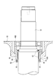
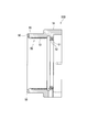
また、図2に示されるように、筒状シール部材50Bの内部空間14側の端部(筒状他端部[cylindrical another end])55には、接地導体60がネジ63によって固定されている。なお、ネジ63の正確な位置は、図4中のネジ穴64a及び図5中のネジ孔64bによって示されている。接地導体60は、図5に示されるように、環状導電フレーム61を備えており、環状導電フレーム61の内周面61a上に多数の繊維状導体[fiber-like conductors](導電体[electrical conductors]:導電ブラシ[conductive brush])62が内方に向けて植設されている。回転軸32が接地導体60及び筒状シール部材50Bに挿通されると、繊維状導体62の先端は、回転軸32の外周面に接する。
回転子30は、筒状の回転コイル[rotor coil]31と回転軸[rotor shaft]32とで構成されている。回転コイル31は、筒状の鉄心にコイルが巻かれて構成されている。回転コイルに31に回転軸32が挿通されて固定されている。また、回転子30は、回転コイル31が固定子20の内部に位置する状態で、軸受40A及び40Bを介して端壁12及び貫通壁13に回転可能に支持されている。
図3及び図4に示されるように、筒状シール部材50Bの端部55の接地導体60との接合面には、溝としてバイパス流路56が形成されている。なお、バイパス流路は、接地導体60上に溝として形成されても良い。あるいは、筒状シール部材50B及び接地導体60の双方に溝として形成されても良い。バイパス流路を接合面に溝として形成すると、容易な加工でバイパス流路を形成することができる。
ここで、回転軸32の軸方向から見て、バイパス流路56の総断面積(総流路断面積)は、繊維状導体62が設けられている隙間(環状導電フレーム61と回転軸32との間の隙間)の断面積よりも大きくされている。即ち、バイパス流路56の流通抵抗は、繊維状導体62が設けられている隙間(環状導電フレーム61と回転軸32との間の隙間)の流通抵抗よりも小さい。
また、電動モータ1は、冷却機構として冷媒流路[cooling flow paths]15を備えている。冷媒流路15は、電動モータ1の外部から供給された冷媒がモータケース10内を循環するための経路である。冷媒流路15は、周壁11と固定鉄心21との間に形成されている。外部から供給された液冷媒は、冷媒流路15を通過する間に固定鉄心21を冷却し、液冷媒の一部は気冷媒になる。固定鉄心21を冷却した冷媒は、気液混合状態で内部空間14の端壁12側に排出されて、コイルエンド22を冷却する。コイルエンド22を冷却した冷媒はそのほとんど全てが気冷媒となる。
液冷媒の気冷媒への変化によって、内部空間14の端壁12側の圧力が上昇し、気冷媒は、固定鉄心21と回転コイル31との間の隙間を通って、圧力が低い内部空間14の貫通壁13側に移動する。内部空間14の貫通壁13側に移動した気冷媒は、モータケース10に設けられた排出口(図示せず)を通ってモータケース10外部の冷媒循環路に排出される。また、内部空間14の貫通壁13側に移動した気冷媒は、バイパス流路56及びコロ軸受40Bの外側の流路70(図2参照)を通って圧力の低いモータケース10外部に流出する。なお、気冷媒は、コロ軸受40Bの外側の流路70だけでなく、コロ軸受40B自体も通過し得る。
上述したように、液冷媒の気冷媒への変化によって、モータケース10の内部圧力が外部圧力よりも高くなり、気冷媒がコロ軸受40Bの外側の流路70を通ってモータケース10の外部に流出する。この際、気冷媒は、コロ軸受40Bの外側の流路70に達する前に、繊維状導電体62ではなくバイパス流路56を通過する。このため、気冷媒は、繊維状導電体62をほとんど通過せず、繊維状導電体62に損傷を与えることはなく、回転軸32に帯電した電荷(軸電流)が繊維状導電体62を介して安定的に除去される。
また、バイパス流路56の流路断面積が、繊維状導体62が設けられている隙間(環状導電フレーム61と回転軸32との間の隙間)の断面積よりも大きくされているので、気冷媒は、流通抵抗の小さいバイパス流路56を通ってモータケース10の外部に流出する。このため、繊維状導電体62の損傷がより一層回避され、回転軸32に帯電した電荷(軸電流)が繊維状導電体62を介してより安定的に除去される。
さらに、少量の気冷媒は繊維状導体62を通過し得るが、接地導体60が筒状シール部材50Bの内部空間14側の端部55に配置されることで電動モータ1の外部に流出する冷媒量が低減されるので、気冷媒の流速が低下して繊維状導体62の損傷がより一層回避され、回転軸32に帯電した電荷(軸電流)が繊維状導電体62を介してより安定的に除去される。
また、エンドミルによる切削等の比較的簡単な加工によって筒状シール部材50Bにバイパス流路56を形成することができ、バイパス流路56は接地導体60の電荷除去性能に影響を及ぼすこともない。
なお、上記実施形態では、接地導体60は、環状フレーム61を備えて環状に形成された。しかし、接地導体は環状に限定されない。例えば、接地導体は、回転軸32の外周面の一部に沿った半円弧状などの部分円弧状に形成されても良く、種々の形状を採ることができる。
また、上記実施形態では、接地導体60の環状フレーム61の内周面61aに繊維状導体(導電体)62が密集して植設された。しかし、導電体は繊維状部材に限定されない。例えば、導電体は、シート部材を回転軸32の軸方向に沿って内周面61a上に配置し、シート部材の表面が回転軸32の表面と接するように構成されても良く、種々の形状を採ることができる。
また、本実施形態では、バイパス流路56を通った気冷媒は、コロ軸受40Bの外側の流路70(及びコロ軸受40B自体)を通って、モータケース10の外部に流出する。しかし、上述した流路70以外に、気冷媒の流路が設けられても良い。
Claims (5)
- 電動モータであって、
内部に内部空間が形成されたモータケースと、
前記モータケースの壁面を貫通するように配置された軸受と、
前記軸受に回転可能に支持された回転軸と、
前記モータケースに固定された、フレーム及び前記フレームに設けられた導電体を有する接地導体とを備えており、
前記フレームが、前記回転軸の外周に沿った環状又は円弧状の内周面を有し、かつ、前記モータケースに固定され、
前記導電体は、当該導電体の先端が前記回転軸に摺接するように、前記フレームの前記内周面に配設され、
前記接地導体と前記モータケースとの間にバイパス流路が設けられ、
前記バイパス流路を介して、前記内部空間と前記モータケースの外部とが連通されている、ことを特徴とする電動モータ。 - 請求項1記載の電動モータであって、
前記モータケースの外部よりも高圧のガスが前記内部空間に充填されている、ことを特徴とする電動モータ。 - 請求項1又は2記載の電動モータであって、
前記バイパス流路の流路断面積が、前記フレームと前記回転軸との間の隙間の断面積よりも大きく設定されている、ことを特徴とする電動モータ。 - 請求項1~3のいずれか1項に記載の電動モータであって、
前記モータケースが筒状シール部材を有しており、
前記シール部材の内面にラビリンスシールが形成され、
前記シール部材の筒状一端部が前記モータケースに固定され、
前記回転軸が前記シール部材に挿通され、
前記接地導体が、前記シール部材の筒状他端部に取り付けられることで前記モータケースに固定されている、ことを特徴とする電動モータ。 - 請求項1~請求項4のいずれか1項に記載の電動モータであって、
前記バイパス流路が、前記接地導体の前記フレームと前記モータケースとの接合面において前記フレーム及び前記モータケースの少なくとも一方に溝として形成されている、ことを特徴とする電動モータ。
Priority Applications (3)
| Application Number | Priority Date | Filing Date | Title |
|---|---|---|---|
| EP12811726.4A EP2733827B1 (en) | 2011-07-13 | 2012-07-06 | Electrical motor |
| CN201280034178.7A CN103650300B (zh) | 2011-07-13 | 2012-07-06 | 电动马达 |
| US14/104,005 US9276451B2 (en) | 2011-07-13 | 2013-12-12 | Electrical motor |
Applications Claiming Priority (2)
| Application Number | Priority Date | Filing Date | Title |
|---|---|---|---|
| JP2011-154720 | 2011-07-13 | ||
| JP2011154720A JP5704002B2 (ja) | 2011-07-13 | 2011-07-13 | 電動モータ |
Related Child Applications (1)
| Application Number | Title | Priority Date | Filing Date |
|---|---|---|---|
| US14/104,005 Continuation US9276451B2 (en) | 2011-07-13 | 2013-12-12 | Electrical motor |
Publications (1)
| Publication Number | Publication Date |
|---|---|
| WO2013008749A1 true WO2013008749A1 (ja) | 2013-01-17 |
Family
ID=47506039
Family Applications (1)
| Application Number | Title | Priority Date | Filing Date |
|---|---|---|---|
| PCT/JP2012/067338 Ceased WO2013008749A1 (ja) | 2011-07-13 | 2012-07-06 | 電動モータ |
Country Status (5)
| Country | Link |
|---|---|
| US (1) | US9276451B2 (ja) |
| EP (1) | EP2733827B1 (ja) |
| JP (1) | JP5704002B2 (ja) |
| CN (1) | CN103650300B (ja) |
| WO (1) | WO2013008749A1 (ja) |
Cited By (1)
| Publication number | Priority date | Publication date | Assignee | Title |
|---|---|---|---|---|
| JP2018063050A (ja) * | 2017-12-14 | 2018-04-19 | 光洋シーリングテクノ株式会社 | シール部材 |
Families Citing this family (15)
| Publication number | Priority date | Publication date | Assignee | Title |
|---|---|---|---|---|
| US9917491B2 (en) | 2014-03-07 | 2018-03-13 | Nidec Motor Corporation | Ground ring and enclosure in an electric motor |
| JP6097720B2 (ja) * | 2014-04-23 | 2017-03-15 | 本田技研工業株式会社 | 導電性接続体 |
| JP6127308B2 (ja) * | 2015-05-01 | 2017-05-17 | 株式会社明電舎 | 回転機 |
| US20180087521A1 (en) * | 2016-08-15 | 2018-03-29 | Luraco Technologies, Inc. | Fluid sealing member and fluid pump and motor having fluid sealing member |
| US11698079B2 (en) * | 2017-09-09 | 2023-07-11 | Luraco, Inc. | Fluid sealing member and fluid pump and motor having fluid sealing member |
| CN106253589A (zh) * | 2016-08-16 | 2016-12-21 | 中车永济电机有限公司 | 易维护接地装置 |
| JP6330893B2 (ja) * | 2016-12-05 | 2018-05-30 | 株式会社明電舎 | 回転機 |
| KR20190068972A (ko) * | 2017-12-11 | 2019-06-19 | 현대자동차주식회사 | 구동모터의 접지 구조체 |
| CN111211648A (zh) * | 2018-11-21 | 2020-05-29 | 苏州加拉泰克动力有限公司 | 无刷电机 |
| US11754186B2 (en) * | 2020-11-17 | 2023-09-12 | Rolls-Royce North American Technologies, Inc. | Grounding brush seals |
| CN113922599A (zh) * | 2021-11-16 | 2022-01-11 | 浙江极氪智能科技有限公司 | 一种电机轴电压的柔性接地结构 |
| DE102022101754B4 (de) | 2022-01-26 | 2026-03-26 | Schaeffler Technologies AG & Co. KG | Elektrische Rotationsmaschine, elektrisches Antriebssystem und Getriebemotoreinheit |
| CN114454721B (zh) * | 2022-03-30 | 2024-07-19 | 广汽埃安新能源汽车有限公司 | 电动汽车降低电机轴承电腐蚀方法及电动汽车 |
| DE102023201006A1 (de) * | 2023-02-08 | 2024-08-08 | Zf Friedrichshafen Ag | Anordnung zur Erdung einer Welle |
| SE547520C2 (en) * | 2024-02-16 | 2025-10-07 | Traton Ab | Electric machine with grounding ring and method for assembling the electric machine |
Citations (5)
| Publication number | Priority date | Publication date | Assignee | Title |
|---|---|---|---|---|
| JPS5612456U (ja) * | 1979-07-05 | 1981-02-02 | ||
| JPS5694156U (ja) * | 1979-12-21 | 1981-07-27 | ||
| JP2008537469A (ja) * | 2005-04-20 | 2008-09-11 | イリノイ トゥール ワークス インコーポレイティド | 軸電流コントロールブラシリング組立体 |
| JP4485897B2 (ja) | 2003-10-06 | 2010-06-23 | イリノイ トゥール ワークス インコーポレイティド | モーターシャフト上の電流を緩和するための接地ブラシ |
| JP2010525787A (ja) | 2007-04-23 | 2010-07-22 | イリノイ トゥール ワークス インコーポレイティド | 回転シャフトの電流を低減するための改良された接地ブラシシステム |
Family Cites Families (16)
| Publication number | Priority date | Publication date | Assignee | Title |
|---|---|---|---|---|
| JPS5922861B2 (ja) | 1979-07-09 | 1984-05-29 | タキロン株式会社 | 採光用ド−ムの施工方法 |
| JPS5694156A (en) | 1979-12-27 | 1981-07-30 | Matsushita Electric Ind Co Ltd | Process for making solar energy selective absorption film |
| US4739204A (en) * | 1986-01-30 | 1988-04-19 | Mitsubishi Denki Kabushiki Kaisha | Liquid cooled a.c. vehicle generator |
| US5402023A (en) * | 1992-08-07 | 1995-03-28 | Nippon Densan Corporation | Spindle motor and magnetic fluid seal apparatus used therefor |
| US8199453B2 (en) | 2003-03-17 | 2012-06-12 | Illinois Tool Works Inc. | Shaft current control brush ring assembly |
| US7136271B2 (en) | 2003-03-17 | 2006-11-14 | Illinois Tool Works Inc | Static charge neutralizing assembly for use on rollers and shafts |
| CN100536285C (zh) * | 2003-10-06 | 2009-09-02 | 伊利诺斯器械工程公司 | 用于缓和马达轴上的电流的接地刷 |
| CN1259765C (zh) * | 2003-11-28 | 2006-06-14 | 湖南大学 | 可预防电机定转子静电放电的装置 |
| US7207774B2 (en) * | 2004-03-17 | 2007-04-24 | Japan Servo Co., Ltd. | Centrifugal fan and casing thereof |
| US8664812B2 (en) * | 2006-03-17 | 2014-03-04 | Inpro/Seal Llc | Current diverter ring |
| US20110204734A1 (en) * | 2005-06-25 | 2011-08-25 | Orlowski David C | Motor Grounding Seal |
| US7528513B2 (en) * | 2005-08-17 | 2009-05-05 | Illinois Tool Works Inc. | Shaft current control brush assembly with drainage |
| JP2007143207A (ja) * | 2005-11-14 | 2007-06-07 | Asmo Co Ltd | 回転電機及び車両用送風機 |
| US8421286B2 (en) * | 2008-07-03 | 2013-04-16 | Nidec Motor Corporation | Kit and method for attaching a grounding ring to an electrical motor |
| US8183727B2 (en) * | 2008-11-24 | 2012-05-22 | Caterpillar Inc. | Grounding mechanism for electric motor |
| WO2010118270A2 (en) * | 2009-04-09 | 2010-10-14 | Inpro/Seal Llc | Current diverter ring |
-
2011
- 2011-07-13 JP JP2011154720A patent/JP5704002B2/ja not_active Expired - Fee Related
-
2012
- 2012-07-06 WO PCT/JP2012/067338 patent/WO2013008749A1/ja not_active Ceased
- 2012-07-06 EP EP12811726.4A patent/EP2733827B1/en active Active
- 2012-07-06 CN CN201280034178.7A patent/CN103650300B/zh active Active
-
2013
- 2013-12-12 US US14/104,005 patent/US9276451B2/en active Active
Patent Citations (5)
| Publication number | Priority date | Publication date | Assignee | Title |
|---|---|---|---|---|
| JPS5612456U (ja) * | 1979-07-05 | 1981-02-02 | ||
| JPS5694156U (ja) * | 1979-12-21 | 1981-07-27 | ||
| JP4485897B2 (ja) | 2003-10-06 | 2010-06-23 | イリノイ トゥール ワークス インコーポレイティド | モーターシャフト上の電流を緩和するための接地ブラシ |
| JP2008537469A (ja) * | 2005-04-20 | 2008-09-11 | イリノイ トゥール ワークス インコーポレイティド | 軸電流コントロールブラシリング組立体 |
| JP2010525787A (ja) | 2007-04-23 | 2010-07-22 | イリノイ トゥール ワークス インコーポレイティド | 回転シャフトの電流を低減するための改良された接地ブラシシステム |
Non-Patent Citations (1)
| Title |
|---|
| See also references of EP2733827A4 |
Cited By (1)
| Publication number | Priority date | Publication date | Assignee | Title |
|---|---|---|---|---|
| JP2018063050A (ja) * | 2017-12-14 | 2018-04-19 | 光洋シーリングテクノ株式会社 | シール部材 |
Also Published As
| Publication number | Publication date |
|---|---|
| US20140097714A1 (en) | 2014-04-10 |
| EP2733827A1 (en) | 2014-05-21 |
| EP2733827A4 (en) | 2016-01-20 |
| EP2733827B1 (en) | 2017-09-06 |
| CN103650300A (zh) | 2014-03-19 |
| JP5704002B2 (ja) | 2015-04-22 |
| US9276451B2 (en) | 2016-03-01 |
| JP2013021860A (ja) | 2013-01-31 |
| CN103650300B (zh) | 2016-01-06 |
Similar Documents
| Publication | Publication Date | Title |
|---|---|---|
| WO2013008749A1 (ja) | 電動モータ | |
| JP6098136B2 (ja) | 回転電機 | |
| US10180271B2 (en) | Multiple cylinder rotary compressor and refrigeration cycle apparatus | |
| US9520756B2 (en) | Linear electromechanical actuator | |
| US20080042363A1 (en) | Electric rotating machine | |
| US9929526B2 (en) | Contact type power feeding apparatus | |
| CN203933231U (zh) | 电动机、负载结合体以及具备负载结合体的空气调节机 | |
| JP6111912B2 (ja) | ターボ圧縮機及びターボ冷凍機 | |
| US20060043682A1 (en) | Self-cooling ferrfluid seal | |
| US20190128321A1 (en) | Journal device and rotary machine | |
| US6377658B1 (en) | Seal for liquid metal bearing assembly | |
| JP5953933B2 (ja) | ステータおよび圧縮機 | |
| BR112023013936A2 (pt) | Máquina elétrica | |
| JP2019173911A (ja) | 軸受装置の冷却構造 | |
| US20120138519A1 (en) | Cooling device for spindle sealing and/or bearing means | |
| CN104047958B (zh) | 轴承套 | |
| JP2014050281A (ja) | ステータおよび圧縮機 | |
| JP2012231584A (ja) | 容積形圧縮機 | |
| CN108071591B (zh) | 制冷剂压缩机 | |
| US10514062B2 (en) | Journal device and rotary machine | |
| CN104047956B (zh) | 轴承套 | |
| JP2016180311A (ja) | 電動コンプレッサ | |
| JP2008082279A (ja) | 電動コンプレッサ | |
| JP5034476B2 (ja) | 圧縮機および空気調和機および給湯機 | |
| CN110581615B (zh) | 超高速电机的转子结构 |
Legal Events
| Date | Code | Title | Description |
|---|---|---|---|
| 121 | Ep: the epo has been informed by wipo that ep was designated in this application |
Ref document number: 12811726 Country of ref document: EP Kind code of ref document: A1 |
|
| NENP | Non-entry into the national phase |
Ref country code: DE |
|
| REEP | Request for entry into the european phase |
Ref document number: 2012811726 Country of ref document: EP |
|
| WWE | Wipo information: entry into national phase |
Ref document number: 2012811726 Country of ref document: EP |