WO2013011581A1 - Capsule anti-égouttement - Google Patents
Capsule anti-égouttement Download PDFInfo
- Publication number
- WO2013011581A1 WO2013011581A1 PCT/JP2011/066476 JP2011066476W WO2013011581A1 WO 2013011581 A1 WO2013011581 A1 WO 2013011581A1 JP 2011066476 W JP2011066476 W JP 2011066476W WO 2013011581 A1 WO2013011581 A1 WO 2013011581A1
- Authority
- WO
- WIPO (PCT)
- Prior art keywords
- cap
- flow path
- flange
- spout
- auxiliary flow
- Prior art date
- Legal status (The legal status is an assumption and is not a legal conclusion. Google has not performed a legal analysis and makes no representation as to the accuracy of the status listed.)
- Ceased
Links
Images
Classifications
-
- B—PERFORMING OPERATIONS; TRANSPORTING
- B65—CONVEYING; PACKING; STORING; HANDLING THIN OR FILAMENTARY MATERIAL
- B65D—CONTAINERS FOR STORAGE OR TRANSPORT OF ARTICLES OR MATERIALS, e.g. BAGS, BARRELS, BOTTLES, BOXES, CANS, CARTONS, CRATES, DRUMS, JARS, TANKS, HOPPERS, FORWARDING CONTAINERS; ACCESSORIES, CLOSURES, OR FITTINGS THEREFOR; PACKAGING ELEMENTS; PACKAGES
- B65D47/00—Closures with filling and discharging, or with discharging, devices
- B65D47/36—Closures with frangible parts adapted to be pierced, torn or removed, to provide discharge openings
-
- B—PERFORMING OPERATIONS; TRANSPORTING
- B65—CONVEYING; PACKING; STORING; HANDLING THIN OR FILAMENTARY MATERIAL
- B65D—CONTAINERS FOR STORAGE OR TRANSPORT OF ARTICLES OR MATERIALS, e.g. BAGS, BARRELS, BOTTLES, BOXES, CANS, CARTONS, CRATES, DRUMS, JARS, TANKS, HOPPERS, FORWARDING CONTAINERS; ACCESSORIES, CLOSURES, OR FITTINGS THEREFOR; PACKAGING ELEMENTS; PACKAGES
- B65D47/00—Closures with filling and discharging, or with discharging, devices
- B65D47/40—Closures with filling and discharging, or with discharging, devices with drip catchers or drip-preventing means
Definitions
- the present invention relates to a cap for preventing dripping.
- a cap provided with a spout is attached to the opening of a bottle container that often pours the content liquid into a palm or a small container like a container for storing lotion.
- a cap for example, a cap provided with various functions such as one configured to be able to dispense a predetermined amount has been proposed (for example, see Patent Document 1).
- the present invention has been made in view of such circumstances, and provides a dripping prevention cap capable of effectively preventing dripping.
- a cap having a spout can be detachably attached to an opening of a container for storing liquid,
- An openable obstruction formed in the middle of the liquid flow path, a sagging prevention flange formed in a direction perpendicular to the end portion end surface of the flow path, and a flow gap between the flow path and the end of the flow path
- a separate auxiliary flow path cap that can be fitted, and a spout flange that extends a top plate of the auxiliary flow path cap to form a constant pouring space between the sagging prevention flange; did.
- the spout has a flow passage communicating with the container and an open end formed at the end of the flow passage. And an upper flange and a lower flange project from the upper end edge and the lower end edge of the opening end portion in a direction perpendicular to the flow passage.
- a partition wall is projected from a portion facing the flow gap of the auxiliary flow path cap.
- the lower end of the partition wall is characterized by being configured to open a closing body formed in the middle of the liquid flow path when the auxiliary flow path cap is fitted to the lower end of the cap flow path.
- a cap having a spout can be detachably attached to an opening of a container for storing a liquid, and the cap is an openable blockage formed in the middle of a liquid flow path.
- the top plate of the auxiliary flow path cap is extended to form a spout flange that forms a constant pour space between the sagging prevention flange, it is possible to effectively prevent dripping. .
- the spout includes a flow passage communicating with the container and an opening end formed at a terminal end of the flow passage, and an upper end edge and a lower end edge of the opening end portion. Since the upper flange and the lower flange project in a direction perpendicular to the flow path, liquid dripping can be more effectively prevented.
- the partition wall protrudes from the portion facing the flow gap of the auxiliary flow path cap, and the lower end of the partition wall is fitted to the lower end of the cap flow path.
- the closed body formed in the middle of the liquid flow path is opened, the dripping can be more effectively prevented.
- FIG. 3 is a cross-sectional view taken along line AA in FIG. It is explanatory drawing which showed the auxiliary
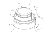
- FIG. 1 is an explanatory view showing an appearance of a cap A as a liquid dripping prevention cap according to the present embodiment.
- the cap A is attached to the opening 12 of the bottle 11 of the bottled lotion 10 containing the lotion therein, and the inside of the cap A from the spout 13 provided in the cap A.
- the lotion can be taken out through the flow passage formed in the.
- the cap A is composed of a cap main body 15 attached to the opening 12 of the bottle 11 and an auxiliary flow path cap 17 detachably attached to the cap main body 15.
- Reference numeral 16 in the figure denotes a cover body 16 that covers the upper portion of the cap body 15.
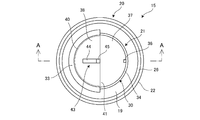
- FIG. 2 is an explanatory view showing the cap main body 15 in a top view
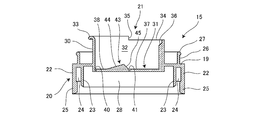
- FIG. 3 is a cross-sectional view taken along the line AA in FIG.
- the cap body 15 includes a base 20 that is fitted into the opening 12 of the bottle 11 and an auxiliary flow path cap mounting portion 21 to which the auxiliary flow path cap 17 is mounted. Yes.
- the base 20 has a circular intermediate wall 19 that extends in the horizontal direction above the opening 12 when attached to the bottle 11, and an outer diameter of the opening 12 that hangs downward from the outer edge of the intermediate wall 19.
- a base peripheral wall 22 having an inner diameter of the same diameter, and an outer diameter that is substantially the same as the inner diameter of the opening 12 that extends concentrically inwardly from the intermediate wall 19 inside the base peripheral wall 22.
- An inner wall body 23 is provided, and a fitting groove 24 for fitting the peripheral wall of the opening 12 of the bottle 11 is formed between the base peripheral wall body 22 and the inner wall body 23.
- the inner side of the inner wall body 23 is a base circulation space 28 in which the lotion contained in the bottle 11 circulates.
- a huge portion 25 bulging inward of the base peripheral wall body 22 is formed, and a thin portion (not shown) provided on the peripheral wall of the opening 12.
- the cap body 15 is detachable from the bottle 11 and the cap body 15 is not easily detached from the bottle 11.
- cover body mounting wall 26 In the vicinity of the outer edge of the upper surface of the intermediate wall 19, there is provided a peripheral wall-like cover body mounting wall 26 that is formed to rise upward.
- the cover body mounting wall 26 is a part for locking the cover body 16, and the outer diameter thereof is substantially the same as the inner diameter of the cover body 16.
- a peripheral protrusion 27 bulging outward is formed at the upper end of the cover body mounting wall 26 and is engaged with a groove (not shown) formed on the inner peripheral surface of the cover body 16.
- the cover body 16 can be locked so as to be freely opened and closed.
- the auxiliary flow path cap mounting portion 21 includes a mounting portion peripheral wall body 30 disposed concentrically with the inner wall body 23 and penetrating the intermediate wall 19, and a bottom wall portion blocking the lower portion of the mounting portion peripheral wall body 30.
- the auxiliary flow path cap mounting space 32 is formed on the inner side.
- the mounting portion peripheral wall body 30 has a cylindrical shape with an outer diameter smaller than the inner diameter of the inner wall body 23, and as shown in FIG. 2, the substantially half portion of the upper edge is substantially perpendicular to the outer side in the radial direction.
- a sagging prevention flange 33 is provided that is curved while projecting in a direction, and further has a tip curved downward.
- the remaining half of the upper peripheral edge of the mounting portion peripheral wall body 30 is a low edge portion 34 formed slightly lower than the upper edge of the sagging prevention flange 33, and the sagging prevention flange 33 and the low edge portion 34 are interposed between them. Is provided with a stepped portion 35.
- the inner peripheral wall surface of the mounting portion peripheral wall body 30 provided with the low edge portion 34 is a protrusion that regulates the rotation of the auxiliary flow path cap 17 mounted on the auxiliary flow path cap mounting portion 21 in the circumferential direction.
- the strip portion 36 is formed in the vertical direction, and the upper end thereof is formed with a taper inclined in the downward direction toward the inside of the mounting portion peripheral wall body 30.
- the bottom wall portion 31 is a part having a role of partitioning the content liquid (in the present embodiment, lotion) contained in the bottle 11 from the outside of the bottle 11, and is a fixed-side bottom wall formed on the low edge portion 34 side. 37 and a rocking side bottom wall 38 formed on the sagging prevention flange 33 side.
- the fixed-side bottom wall 37 is a semicircular portion in a top view and is connected to the mounting portion peripheral wall body 30 with sufficient strength. As will be described in detail later, when the auxiliary flow path cap 17 is pressed down, It functions as one of the contact seats that contact the lower portion of the flow path cap 17 and restrict further movement downward.
- the swing-side bottom wall 38 is a semicircular portion when viewed from above, and a semicircular arc-shaped cutting groove 40 cut along the mounting portion peripheral wall body 30 at the periphery thereof and a fixed-side bottom wall 37. And a linear rocking coupling groove 41 carved in an adjacent portion.
- the cutting groove 40 is a groove that is easily cut when the rocking side bottom wall 38 is pressed from above, and the rocking connection groove 41 is a groove that serves as a folding groove. Therefore, when the swinging side bottom wall 38 is pressed from above, the swinging side bottom wall 38 falls to the base circulation space 28 side in a state where it is connected to the fixed side bottom wall 37 by the swinging connection groove 41. Thus, the auxiliary flow path cap mounting space 32 and the base circulation space 28 are communicated and opened. That is, the rocking side bottom wall 38 functions as an openable closing body.
- an abutting projection 43 formed by extending in a direction substantially orthogonal to the extending direction of the swing connecting groove 41 is provided at a substantially central portion of the swing side bottom wall 38.
- the contact protrusion 43 is a part having a role of assisting the dropping of the rocking side bottom wall 38 or holding the rocking side bottom wall 38 in an open state when the auxiliary flow path cap 17 is pushed.
- the first oblique portion 44 is formed more gently than the second oblique portion 45, and the second oblique portion 45 has an angle of approximately 45 degrees.
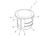
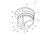
- FIGS. 4 is an explanatory view showing the auxiliary flow path cap 17 as viewed from obliquely above
- FIG. 5 is an explanatory view showing the auxiliary flow path cap 17 as viewed from obliquely below
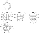
- FIG. It is explanatory drawing which showed the front surface, the rear surface, and the right side surface.
- the auxiliary flow path cap 17 includes a substantially cylindrical body wall body 50 having an outer diameter substantially the same as the inner diameter of the mounting portion peripheral wall body 30, and an upper surface of the body wall body 50.
- the top plate 51 is provided.
- the top plate 51 is a plate-like member having a substantially circular shape when viewed from above, and includes a spout flange 56 as an upper flange formed by extending forward at the front portion thereof.
- the trunk wall body 50 is configured such that the lower rear half is configured horizontally, and the lower front half is configured to be inclined downward toward the front.
- the trunk wall body 50 includes two flow grooves 52 that are substantially U-shaped in cross-section and extend in the vertical direction below the spout flange 56, and a partition wall 53 is formed between the flow grooves 52. Is formed.
- the flow groove 52 is a groove for flowing the content liquid when the swinging side bottom wall 38 is dropped and is in an open state, and is formed from the lower part of the auxiliary flow path cap 17 to the back surface of the top plate 51. Is formed.
- the partition wall 53 is a plate-like member that is formed between the two flow grooves 52 and extends in the up-down direction, and a lower end portion thereof (hereinafter referred to as a partition wall lower end portion 54) is the auxiliary flow path cap 17. It is set as the site
- the partition wall lower end portion 54 will be described in detail later in the description of the operation, the partition wall lower end portion 54 is responsible for separating the swing-side bottom wall 38 from the mounting portion peripheral wall body 30 and the initial pushing operation in the cutting groove 40 portion.
- a partition wall oblique portion 55 that is inclined toward the back side of the trunk wall body 50 is formed on the upper portion of the partition wall 53, and the liquid flowing through the left and right flow grooves 52 can be in contact with each other. is doing.
- a low edge contact body 57 is provided in which the wall of the body wall body 50 is formed in a thick plate shape outward in the radial direction.
- a sliding groove 58 that fits with the above-described protruding strip portion 36 is provided from the lower portion of the auxiliary flow path cap 17 toward the low edge portion. Up to the lower end of the contact body 57, it is formed in the vertical direction.
- a projecting piece support plate 59 having a surface spread in the front-rear and up-down directions is disposed inside the body wall body 50, and the projecting piece support plate 59 side of the projecting piece support plate 59 A locking protrusion 60 is provided below the end.
- the locking protrusion 60 is disposed at a position where it can come into contact with the contact protrusion 43 when the auxiliary flow path cap 17 is mounted on the auxiliary flow path cap mounting portion 21 and pressed down.
- the locking projection piece 60 includes a projection piece tip portion 61 and a projection piece oblique portion 62.
- the projecting piece tip 61 is a portion having a substantially horizontal surface, and will be described in detail later in the description of the operation, and is responsible for the pushing operation of the middle plate of the rocking side bottom wall 38 separated from the mounting portion peripheral wall body 30. .
- the projecting piece inclined portion 62 is a part having a surface inclined upward at an angle of about 45 degrees from the projecting tip end portion 61 to the rear surface direction, and is separated from the mounting portion peripheral wall body 30 on the swinging side bottom. Responsible for locking and fixing the wall 38.
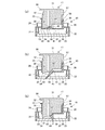
- FIG. 7A shows a state where the auxiliary flow path cap 17 is mounted on the auxiliary flow path cap mounting portion 21 of the cap body 15 and the plug opening operation is not performed.
- the top plate 51 of the auxiliary flow path cap 17 is pressed down, and the auxiliary flow path cap 17 is directed downward in the auxiliary flow path cap mounting space 32 along the mounting portion peripheral wall body 30. Move.
- the auxiliary flow path cap 17 is pushed in straightly with the rotation in the circumferential direction being suppressed by the sliding groove 58 and the protrusion 36 being fitted and sliding.
- the partition wall lower end portion 54 of the auxiliary flow path cap 17 comes into contact with the vicinity of the cutting groove 40 of the swing side bottom wall 38 and the pressing force is concentrated, so that the cutting groove 40 is cut and the swing side bottom wall 38 is In other words, in a state where it is pivotally supported by the swing connecting groove 41, in other words, the string portion of the semicircular swing side bottom wall 38 is dropped while functioning like a hinge. That is, the partition wall lower end portion 54 performs the separation and initial pushing operation of the rocking side bottom wall 38 from the mounting portion peripheral wall body 30 in the cutting groove 40 portion.
- the left and right end portions of the low edge portion contact body 57 and the stepped portion 35 formed on the mounting portion peripheral wall body 30 are in contact with each other, whereby the rotation of the auxiliary flow path cap 17 in the circumferential direction is restricted.
- the base circulation space 28 and the circulation groove 52 communicate with each other to form a flow passage, and the spout 13 is formed.
- the spout 13 includes a flow passage communicating with the bottle 11 and an opening end formed at the end of the flow passage, and the upper end edge and the lower end edge of the opening end portion are in circulation.
- the spout flange 56 and the sagging prevention flange 33 are projected in a direction perpendicular to the road. In other words, a constant pouring space is formed between the spout flange 56 and the sagging prevention flange 33, and the spout 13 functions.
- the partition wall 53 is formed with the partition wall oblique portion 55, the lotion that has reached the vicinity of the spout 13 through the flow groove 52 is not blocked by the partition wall 53, so It can come into wide contact with the back surface, and the surface tension and viscosity of the skin lotion can cause the liquid retention effect in the spout 13 to be strong, and the liquid breakage can be improved.
- the sagging prevention flange 33 is formed in a substantially arc shape in cross-section, the liquid runs out well, and the dripping can be further prevented.
- a cap having a spout can be detachably attached to an opening of a container for storing liquid, and the cap is a liquid flow path.
- An openable closing body formed in the middle, a sagging prevention flange formed in a direction perpendicular to the end face of the end portion of the flow passage, and a flow gap between the flow passages to be fitted to the end of the flow passage. Since it consists of a separate auxiliary flow path cap and a spout flange that extends the top plate of the auxiliary flow path cap and forms a constant pouring space between the sagging prevention flange, it is effective for dripping liquid Can be prevented.
Landscapes
- Engineering & Computer Science (AREA)
- Mechanical Engineering (AREA)
- Closures For Containers (AREA)
Abstract
L'invention porte sur une capsule anti-égouttement, laquelle capsule est apte à empêcher efficacement des égouttements. Cette capsule anti-égouttement permet de monter une capsule, qui présente un bec de versage, de façon à être librement attachable et détachable sur l'ouverture d'un récipient qui contient des liquides. La capsule est configurée à partir de : un corps d'occlusion pouvant être librement ouvert qui est formé à mi-chemin dans le canal d'écoulement de liquide ; une bride anti-égouttement formée sur la face d'extrémité terminale du canal d'écoulement dans une direction orthogonale à celui-ci ; une capsule de canal d'écoulement auxiliaire séparée qui peut être librement adaptée dans l'extrémité du canal d'écoulement, maintenant un espace d'écoulement entre ladite capsule et le canal d'écoulement ; et une bride de bec verseur qui est une extension de la plaque supérieure de la capsule de canal d'écoulement auxiliaire et qui forme un espace de versage fixe entre ladite bride et la bride anti-égouttement.
Priority Applications (4)
| Application Number | Priority Date | Filing Date | Title |
|---|---|---|---|
| PCT/JP2011/066476 WO2013011581A1 (fr) | 2011-07-20 | 2011-07-20 | Capsule anti-égouttement |
| CN201180072414.XA CN103826983B (zh) | 2011-07-20 | 2011-07-20 | 用于防止液体滴落的盖 |
| JP2013524556A JP5852651B2 (ja) | 2011-07-20 | 2011-07-20 | 液垂れ防止用キャップ |
| TW101114690A TWI534046B (zh) | 2011-07-20 | 2012-04-25 | Anti-drip with cap |
Applications Claiming Priority (1)
| Application Number | Priority Date | Filing Date | Title |
|---|---|---|---|
| PCT/JP2011/066476 WO2013011581A1 (fr) | 2011-07-20 | 2011-07-20 | Capsule anti-égouttement |
Publications (1)
| Publication Number | Publication Date |
|---|---|
| WO2013011581A1 true WO2013011581A1 (fr) | 2013-01-24 |
Family
ID=47557788
Family Applications (1)
| Application Number | Title | Priority Date | Filing Date |
|---|---|---|---|
| PCT/JP2011/066476 Ceased WO2013011581A1 (fr) | 2011-07-20 | 2011-07-20 | Capsule anti-égouttement |
Country Status (4)
| Country | Link |
|---|---|
| JP (1) | JP5852651B2 (fr) |
| CN (1) | CN103826983B (fr) |
| TW (1) | TWI534046B (fr) |
| WO (1) | WO2013011581A1 (fr) |
Cited By (1)
| Publication number | Priority date | Publication date | Assignee | Title |
|---|---|---|---|---|
| JP2017171313A (ja) * | 2016-03-22 | 2017-09-28 | 英政 箱石 | 開栓具付ペットボトル |
Families Citing this family (1)
| Publication number | Priority date | Publication date | Assignee | Title |
|---|---|---|---|---|
| CN106241024A (zh) * | 2016-08-30 | 2016-12-21 | 江苏德旺化工工业有限公司 | 一种化学防菌瓶 |
Citations (6)
| Publication number | Priority date | Publication date | Assignee | Title |
|---|---|---|---|---|
| JPS4827475Y1 (fr) * | 1970-12-31 | 1973-08-13 | ||
| JPS4827476Y1 (fr) * | 1970-12-31 | 1973-08-13 | ||
| JPS55126053A (en) * | 1979-06-16 | 1980-09-29 | Yoshino Kogyosho Co Ltd | Structure of liquid pouring port edge |
| JPH0323065U (fr) * | 1989-07-11 | 1991-03-11 | ||
| JP2002302146A (ja) * | 2001-04-02 | 2002-10-15 | Okura Ind Co Ltd | 液切れの良好な注出口栓、及び、その用途 |
| JP2003175957A (ja) * | 2001-12-12 | 2003-06-24 | Toyo Seikan Kaisha Ltd | 液切れ促進液体注出キャップ |
Family Cites Families (6)
| Publication number | Priority date | Publication date | Assignee | Title |
|---|---|---|---|---|
| US2715480A (en) * | 1953-03-09 | 1955-08-16 | Jay G Livingstone | Container adapter provided with pouring spout, drip return, and cap |
| CH669575A5 (fr) * | 1985-08-20 | 1989-03-31 | Alfatechnic Ag | |
| CN2249219Y (zh) * | 1996-03-08 | 1997-03-12 | 林山鸿 | 带有导片的瓶盖 |
| JP4251345B2 (ja) * | 1999-07-30 | 2009-04-08 | 株式会社吉野工業所 | 注出キャップ |
| CN201010122Y (zh) * | 2006-12-04 | 2008-01-23 | 林华 | 不滴漏瓶盖 |
| CA2703134C (fr) * | 2007-10-22 | 2012-04-03 | Rene Wilhelm | Perce-feuille pour fermeture de recipient |
-
2011
- 2011-07-20 JP JP2013524556A patent/JP5852651B2/ja not_active Expired - Fee Related
- 2011-07-20 WO PCT/JP2011/066476 patent/WO2013011581A1/fr not_active Ceased
- 2011-07-20 CN CN201180072414.XA patent/CN103826983B/zh not_active Expired - Fee Related
-
2012
- 2012-04-25 TW TW101114690A patent/TWI534046B/zh not_active IP Right Cessation
Patent Citations (6)
| Publication number | Priority date | Publication date | Assignee | Title |
|---|---|---|---|---|
| JPS4827475Y1 (fr) * | 1970-12-31 | 1973-08-13 | ||
| JPS4827476Y1 (fr) * | 1970-12-31 | 1973-08-13 | ||
| JPS55126053A (en) * | 1979-06-16 | 1980-09-29 | Yoshino Kogyosho Co Ltd | Structure of liquid pouring port edge |
| JPH0323065U (fr) * | 1989-07-11 | 1991-03-11 | ||
| JP2002302146A (ja) * | 2001-04-02 | 2002-10-15 | Okura Ind Co Ltd | 液切れの良好な注出口栓、及び、その用途 |
| JP2003175957A (ja) * | 2001-12-12 | 2003-06-24 | Toyo Seikan Kaisha Ltd | 液切れ促進液体注出キャップ |
Cited By (1)
| Publication number | Priority date | Publication date | Assignee | Title |
|---|---|---|---|---|
| JP2017171313A (ja) * | 2016-03-22 | 2017-09-28 | 英政 箱石 | 開栓具付ペットボトル |
Also Published As
| Publication number | Publication date |
|---|---|
| TWI534046B (zh) | 2016-05-21 |
| CN103826983A (zh) | 2014-05-28 |
| JP5852651B2 (ja) | 2016-02-03 |
| JPWO2013011581A1 (ja) | 2015-02-23 |
| CN103826983B (zh) | 2015-07-08 |
| TW201305022A (zh) | 2013-02-01 |
Similar Documents
| Publication | Publication Date | Title |
|---|---|---|
| JP5819595B2 (ja) | 詰め替え容器 | |
| CN102389246B (zh) | 饮料用容器的栓体 | |
| US9321565B2 (en) | Container closure | |
| JP4203912B1 (ja) | 飲料用容器の栓体 | |
| CN102310967B (zh) | 饮料用容器的栓体 | |
| JP5852651B2 (ja) | 液垂れ防止用キャップ | |
| JP2014196135A (ja) | 容器用注出キャップ | |
| JP6108866B2 (ja) | ヒンジキャップ | |
| JP6682145B2 (ja) | ヒンジキャップ | |
| JP5758215B2 (ja) | 詰め替え容器 | |
| JP2016159935A (ja) | 二重容器 | |
| JP2018154373A (ja) | キャップの封止構造 | |
| JP3170795U (ja) | 液垂れ防止用キャップ | |
| JP3178393U (ja) | 飲料容器の栓体 | |
| JP6510825B2 (ja) | キャップ | |
| JP7051277B2 (ja) | ヒンジキャップ | |
| JP7296797B2 (ja) | ヒンジキャップ | |
| KR200407277Y1 (ko) | 배출양 조절이 되는 푸어러 캡 | |
| JP7511531B2 (ja) | 注出キャップ | |
| JP4493924B2 (ja) | ヒンジキャップ | |
| JP5518640B2 (ja) | 注出キャップ | |
| JP7845819B2 (ja) | ヒンジキャップ | |
| JP5990483B2 (ja) | 詰め替え容器 | |
| JP6051118B2 (ja) | 詰め替え容器 | |
| JP7407548B2 (ja) | ヒンジキャップ |
Legal Events
| Date | Code | Title | Description |
|---|---|---|---|
| 121 | Ep: the epo has been informed by wipo that ep was designated in this application |
Ref document number: 11869696 Country of ref document: EP Kind code of ref document: A1 |
|
| DPE1 | Request for preliminary examination filed after expiration of 19th month from priority date (pct application filed from 20040101) | ||
| ENP | Entry into the national phase |
Ref document number: 2013524556 Country of ref document: JP Kind code of ref document: A |
|
| NENP | Non-entry into the national phase |
Ref country code: DE |
|
| 122 | Ep: pct application non-entry in european phase |
Ref document number: 11869696 Country of ref document: EP Kind code of ref document: A1 |