WO2013011916A1 - Guide-chaîne et pignon d'entraînement de chaîne - Google Patents
Guide-chaîne et pignon d'entraînement de chaîne Download PDFInfo
- Publication number
- WO2013011916A1 WO2013011916A1 PCT/JP2012/067808 JP2012067808W WO2013011916A1 WO 2013011916 A1 WO2013011916 A1 WO 2013011916A1 JP 2012067808 W JP2012067808 W JP 2012067808W WO 2013011916 A1 WO2013011916 A1 WO 2013011916A1
- Authority
- WO
- WIPO (PCT)
- Prior art keywords
- chain
- roller
- guide
- chain guide
- timing
- Prior art date
- Legal status (The legal status is an assumption and is not a legal conclusion. Google has not performed a legal analysis and makes no representation as to the accuracy of the status listed.)
- Ceased
Links
Images



Classifications
-
- F—MECHANICAL ENGINEERING; LIGHTING; HEATING; WEAPONS; BLASTING
- F16—ENGINEERING ELEMENTS AND UNITS; GENERAL MEASURES FOR PRODUCING AND MAINTAINING EFFECTIVE FUNCTIONING OF MACHINES OR INSTALLATIONS; THERMAL INSULATION IN GENERAL
- F16H—GEARING
- F16H7/00—Gearings for conveying rotary motion by endless flexible members
- F16H7/18—Means for guiding or supporting belts, ropes, or chains
-
- F—MECHANICAL ENGINEERING; LIGHTING; HEATING; WEAPONS; BLASTING
- F16—ENGINEERING ELEMENTS AND UNITS; GENERAL MEASURES FOR PRODUCING AND MAINTAINING EFFECTIVE FUNCTIONING OF MACHINES OR INSTALLATIONS; THERMAL INSULATION IN GENERAL
- F16H—GEARING
- F16H7/00—Gearings for conveying rotary motion by endless flexible members
- F16H7/08—Means for varying tension of belts, ropes or chains
-
- F—MECHANICAL ENGINEERING; LIGHTING; HEATING; WEAPONS; BLASTING
- F16—ENGINEERING ELEMENTS AND UNITS; GENERAL MEASURES FOR PRODUCING AND MAINTAINING EFFECTIVE FUNCTIONING OF MACHINES OR INSTALLATIONS; THERMAL INSULATION IN GENERAL
- F16C—SHAFTS; FLEXIBLE SHAFTS; ELEMENTS OR CRANKSHAFT MECHANISMS; ROTARY BODIES OTHER THAN GEARING ELEMENTS; BEARINGS
- F16C33/00—Parts of bearings; Special methods for making bearings or parts thereof
- F16C33/30—Parts of ball or roller bearings
- F16C33/58—Raceways; Race rings
- F16C33/62—Selection of substances
-
- F—MECHANICAL ENGINEERING; LIGHTING; HEATING; WEAPONS; BLASTING
- F16—ENGINEERING ELEMENTS AND UNITS; GENERAL MEASURES FOR PRODUCING AND MAINTAINING EFFECTIVE FUNCTIONING OF MACHINES OR INSTALLATIONS; THERMAL INSULATION IN GENERAL
- F16C—SHAFTS; FLEXIBLE SHAFTS; ELEMENTS OR CRANKSHAFT MECHANISMS; ROTARY BODIES OTHER THAN GEARING ELEMENTS; BEARINGS
- F16C13/00—Rolls, drums, discs, or the like; Bearings or mountings therefor
- F16C13/006—Guiding rollers, wheels or the like, formed by or on the outer element of a single bearing or bearing unit, e.g. two adjacent bearings, whose ratio of length to diameter is generally less than one
-
- F—MECHANICAL ENGINEERING; LIGHTING; HEATING; WEAPONS; BLASTING
- F16—ENGINEERING ELEMENTS AND UNITS; GENERAL MEASURES FOR PRODUCING AND MAINTAINING EFFECTIVE FUNCTIONING OF MACHINES OR INSTALLATIONS; THERMAL INSULATION IN GENERAL
- F16C—SHAFTS; FLEXIBLE SHAFTS; ELEMENTS OR CRANKSHAFT MECHANISMS; ROTARY BODIES OTHER THAN GEARING ELEMENTS; BEARINGS
- F16C19/00—Bearings with rolling contact, for exclusively rotary movement
- F16C19/22—Bearings with rolling contact, for exclusively rotary movement with bearing rollers essentially of the same size in one or more circular rows, e.g. needle bearings
- F16C19/44—Needle bearings
- F16C19/46—Needle bearings with one row or needles
- F16C19/466—Needle bearings with one row or needles comprising needle rollers and an outer ring, i.e. subunit without inner ring
-
- F—MECHANICAL ENGINEERING; LIGHTING; HEATING; WEAPONS; BLASTING
- F16—ENGINEERING ELEMENTS AND UNITS; GENERAL MEASURES FOR PRODUCING AND MAINTAINING EFFECTIVE FUNCTIONING OF MACHINES OR INSTALLATIONS; THERMAL INSULATION IN GENERAL
- F16C—SHAFTS; FLEXIBLE SHAFTS; ELEMENTS OR CRANKSHAFT MECHANISMS; ROTARY BODIES OTHER THAN GEARING ELEMENTS; BEARINGS
- F16C2202/00—Solid materials defined by their properties
- F16C2202/02—Mechanical properties
- F16C2202/04—Hardness
-
- F—MECHANICAL ENGINEERING; LIGHTING; HEATING; WEAPONS; BLASTING
- F16—ENGINEERING ELEMENTS AND UNITS; GENERAL MEASURES FOR PRODUCING AND MAINTAINING EFFECTIVE FUNCTIONING OF MACHINES OR INSTALLATIONS; THERMAL INSULATION IN GENERAL
- F16C—SHAFTS; FLEXIBLE SHAFTS; ELEMENTS OR CRANKSHAFT MECHANISMS; ROTARY BODIES OTHER THAN GEARING ELEMENTS; BEARINGS
- F16C2361/00—Apparatus or articles in engineering in general
- F16C2361/63—Gears with belts and pulleys
-
- F—MECHANICAL ENGINEERING; LIGHTING; HEATING; WEAPONS; BLASTING
- F16—ENGINEERING ELEMENTS AND UNITS; GENERAL MEASURES FOR PRODUCING AND MAINTAINING EFFECTIVE FUNCTIONING OF MACHINES OR INSTALLATIONS; THERMAL INSULATION IN GENERAL
- F16C—SHAFTS; FLEXIBLE SHAFTS; ELEMENTS OR CRANKSHAFT MECHANISMS; ROTARY BODIES OTHER THAN GEARING ELEMENTS; BEARINGS
- F16C2361/00—Apparatus or articles in engineering in general
- F16C2361/71—Chains
-
- F—MECHANICAL ENGINEERING; LIGHTING; HEATING; WEAPONS; BLASTING
- F16—ENGINEERING ELEMENTS AND UNITS; GENERAL MEASURES FOR PRODUCING AND MAINTAINING EFFECTIVE FUNCTIONING OF MACHINES OR INSTALLATIONS; THERMAL INSULATION IN GENERAL
- F16H—GEARING
- F16H7/00—Gearings for conveying rotary motion by endless flexible members
- F16H7/08—Means for varying tension of belts, ropes or chains
- F16H2007/0863—Finally actuated members, e.g. constructional details thereof
- F16H2007/0865—Pulleys
-
- F—MECHANICAL ENGINEERING; LIGHTING; HEATING; WEAPONS; BLASTING
- F16—ENGINEERING ELEMENTS AND UNITS; GENERAL MEASURES FOR PRODUCING AND MAINTAINING EFFECTIVE FUNCTIONING OF MACHINES OR INSTALLATIONS; THERMAL INSULATION IN GENERAL
- F16H—GEARING
- F16H7/00—Gearings for conveying rotary motion by endless flexible members
- F16H7/08—Means for varying tension of belts, ropes or chains
- F16H2007/0863—Finally actuated members, e.g. constructional details thereof
- F16H2007/0872—Sliding members
-
- F—MECHANICAL ENGINEERING; LIGHTING; HEATING; WEAPONS; BLASTING
- F16—ENGINEERING ELEMENTS AND UNITS; GENERAL MEASURES FOR PRODUCING AND MAINTAINING EFFECTIVE FUNCTIONING OF MACHINES OR INSTALLATIONS; THERMAL INSULATION IN GENERAL
- F16H—GEARING
- F16H7/00—Gearings for conveying rotary motion by endless flexible members
- F16H7/08—Means for varying tension of belts, ropes or chains
- F16H2007/0889—Path of movement of the finally actuated member
- F16H2007/0893—Circular path
-
- F—MECHANICAL ENGINEERING; LIGHTING; HEATING; WEAPONS; BLASTING
- F16—ENGINEERING ELEMENTS AND UNITS; GENERAL MEASURES FOR PRODUCING AND MAINTAINING EFFECTIVE FUNCTIONING OF MACHINES OR INSTALLATIONS; THERMAL INSULATION IN GENERAL
- F16H—GEARING
- F16H7/00—Gearings for conveying rotary motion by endless flexible members
- F16H7/08—Means for varying tension of belts, ropes or chains
- F16H7/10—Means for varying tension of belts, ropes or chains by adjusting the axis of a pulley
- F16H7/12—Means for varying tension of belts, ropes or chains by adjusting the axis of a pulley of an idle pulley
- F16H7/1254—Means for varying tension of belts, ropes or chains by adjusting the axis of a pulley of an idle pulley without vibration damping means
- F16H7/1281—Means for varying tension of belts, ropes or chains by adjusting the axis of a pulley of an idle pulley without vibration damping means where the axis of the pulley moves along a substantially circular path
-
- F—MECHANICAL ENGINEERING; LIGHTING; HEATING; WEAPONS; BLASTING
- F16—ENGINEERING ELEMENTS AND UNITS; GENERAL MEASURES FOR PRODUCING AND MAINTAINING EFFECTIVE FUNCTIONING OF MACHINES OR INSTALLATIONS; THERMAL INSULATION IN GENERAL
- F16H—GEARING
- F16H7/00—Gearings for conveying rotary motion by endless flexible members
- F16H7/18—Means for guiding or supporting belts, ropes, or chains
- F16H7/20—Mountings for rollers or pulleys
Definitions
- the present invention relates to a chain guide used for adjusting the chain tension or for guiding the movement of the chain, and a chain transmission device using the chain guide.
- the chain transmission device for driving the camshaft in which the timing chain is spanned between the drive sprocket attached to the crankshaft and the driven sprocket attached to the camshaft, the chain can swing to one side of the slack side chain of the timing chain.
- a guide is provided, and the adjustment force of the chain tensioner is applied to the swing side end of the chain guide to tension the timing chain to prevent the chain from loosening and fluttering.
- the chain guide is fixed to the tight chain of the timing chain, and the movement of the timing chain is guided by the fixed chain guide to suppress the flutter.
- both ends of a plurality of roller shafts arranged in a curved shape are supported by a guide base that extends in the moving direction of the timing chain.
- a chain guide is proposed in which a roller comprising a roller bearing is rotatably supported by each of the rollers, and the timing chain is supported by the plurality of rollers so as to be movable.
- the above chain guide is characterized in that the timing chain is guided by rolling of a plurality of rollers, and therefore, the timing chain has a low movement resistance and a small transmission torque cross.
- An object of the present invention is to extend the life of the chain guide by suppressing the wear of the outer surface of the chain guide roller.
- a guide base having a side plate portion that is disposed on a part of the outer periphery of the timing chain and extends long in the moving direction of the timing chain, and the guide base A plurality of roller shafts supported by a shaft support portion formed on the side plate portion and spaced apart in the length direction of the side plate portion, and a chain rotatably supported on each of the plurality of roller shafts
- a configuration is adopted in which the surface hardness of the roller is set to 4 or more points in terms of Rockwell hardness with respect to the surface hardness of the timing chain.
- the swingable chain that guides the movement of the timing chain over one side of the slack side chain of the timing chain, spanning the timing chain between the drive sprocket and the driven sprocket.
- the adjustment force of the chain tensioner is applied to the swing side end portion of the chain guide, and the swing side end portion is pressed against the timing chain.
- the above-described chain guide is adopted.
- a fixed chain guide for guiding the movement of the timing chain is provided on one side of the tight chain of the timing chain, and the chain guide according to the present invention is used as the fixed chain guide.
- the wear of the outer surface of the roller is suppressed by making the surface hardness of the roller at least 4 points in terms of Rockwell hardness with respect to the surface hardness of the timing chain. be able to.
- the surface hardness of the plate that is flexibly connected by the pin is about HRC 50 to 54 in terms of Rockwell hardness. Therefore, the surface hardness of the roller should be higher than that of HRC 58 in terms of Rockwell hardness. Is preferred.
- the surface hardness of the roller is the Rockwell hardness. HRC64 or less is preferable.
- roller material When forming a roller with high surface hardness as described above, high carbon steel is used as the roller material, and after forming the roller, induction hardening or bright quenching is used, or low carbon steel is used as the roller material, and after forming the roller A processing method of carburizing and quenching or carbonitriding and quenching can be employed.
- the roller made of high carbon steel is induction-quenched, or the roller made of low carbon steel is carburized or carbonitrided and hardened to lock against the surface hardness of the timing chain.
- the toughness of the roller is increased compared to the case where the whole is hardened by bright quenching. This can be effective in preventing damage to the roller.
- the roller By adopting a needle roller bearing or a cylindrical roller bearing having an outer ring and a plurality of rollers incorporated inside as the roller, the roller can be smoothly rotated by contact with the chain, and the movement resistance of the chain can be reduced. It can be greatly reduced.
- the hardened layer depth is 0. About 1 to 0.3 mm is preferable.
- the surface hardness of the roller is set at 4 points or more in terms of Rockwell hardness with respect to the surface hardness of the chain, thereby suppressing wear on the outer surface of the roller and extending the service life. Can be planned.
- FIG. 1 Schematic showing the embodiment of the chain transmission according to the present invention
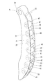
- the perspective view of the chain guide which concerns on this invention 2 is a longitudinal sectional view Right side view of FIG. Sectional view along line VV in FIG. Cross section of the roller shown in FIG. Exploded front view showing part of guide base and rollers Sectional view showing another example of needle roller bearing
- FIG. 1 shows a chain transmission for driving a camshaft, between a drive sprocket 2 attached to the end of a crankshaft 1 and a driven sprocket 4 attached to each of the ends of two camshafts 3.
- the timing chain 5 is spanned.
- the timing chain 5 may be a roller chain or a silent chain.
- the crankshaft 1 rotates in the direction indicated by the arrow in FIG.
- the rotation of the crankshaft 1 moves the timing chain 5 in the direction indicated by the arrow in the figure, and the part from the drive sprocket 2 to one driven sprocket 4 located on the left side in the figure is the slack side, portion from the driven sprocket 4 on the driving sprocket 2 is a tight side, the chain guide a 1 is provided on one side of the slack side chain 5a.
- the chain guide A 1 extends long in the moving direction of the timing chain 5, and its upper end is supported by a fulcrum shaft 14 projecting from the engine block, and can swing about the fulcrum shaft 14. An adjustment force of the chain tensioner 15 is applied to the swing side end portion and is pressed toward the slack side chain 5a.
- a chain guide A 2 is provided on the other side of the tension chain 5 b in the timing chain 5.
- the chain guide A 2 extends in the moving direction of the timing chain 5 in the same manner as the swingable chain guide A 1, and both ends thereof are fixed by tightening bolts 16 screwed into the engine block. It is supposed to guide the movement of.
- the pivotable chain guide A 1 and chain guide A 2 fixed, the same configuration, the insertion hole 24 for shaft insertion is formed on one end portion pivotable chain guide A 1 while there, the chain guide a 2 fixed is only different in that the insertion hole for the bolt inserted into both end portions are formed.
- the chain guide A 1 includes a guide base 21 extending long in the moving direction of the timing chain 5 and a plurality of roller shafts provided at intervals in the length direction of the guide base 21. 31 and a plurality of chain guide rollers 41 rotatably supported on each of the plurality of roller shafts 31.
- the guide base 21 has a configuration in which a plurality of interval holding plates 23 are formed at intervals in the length direction between a pair of opposed side plate portions 22.
- the pair of side plate portions 22 has a bow shape, and an insertion hole 24 into which the fulcrum shaft 14 is inserted is formed at the upper end portion thereof.
- a plurality of bearing recesses 25 that support the shaft end portion of the roller shaft 31 are formed on the opposing inner surfaces of the pair of side plate portions 22 at intervals in the length direction of the side plate portion 22.
- the bearing recess 25 has a tapered groove portion 25 a that faces in the width direction of the side plate portion 22 from the outer surface portion facing the timing chain 5 of the side plate portion 22, and the opening end of the outer surface portion is wide.
- a circular concave portion 25b as a shaft support portion communicating with the narrow end of the tapered groove portion 25a.
- the roller shaft 31 is fitted into the circular recess 25b from the taper groove 25a, and is supported by the circular recess 25b.
- D 1 the width of the narrow portion of the tapered groove 25a, the inner diameter of D 2 of the circular recess 25b, when the outer diameter of the roller shaft 31 is d, and the dimensional relationship of the relationship of d> D 2> D 1 is satisfied
- the roller shaft 31 is pushed into the circular recess 25b from the taper groove 25a, and is fitted and supported with a tightening margin in the circular recess 25b.
- the plurality of bearing recesses 25 have an arcuate arrangement in which a line connecting the centers of the circular recesses 25b draws a convex arcuate line, but may be a curved arrangement.
- the guide base 21 having the above configuration is a synthetic resin molded product. It is preferable to use a resin excellent in oil resistance, weather resistance and strength as a synthetic resin. Examples of such a resin include polyamide 46 (PA46) and polyamide 66 (PA66). In order to further improve the mechanical strength, it is preferable to mix reinforced glass fibers in these resins.
- the guide base 21 may be cast using a light metal such as an aluminum alloy or a magnesium alloy, or may be die-cast.
- the plurality of roller shafts 31 are fitted in the plurality of bearing recesses 25, respectively.
- the roller shaft 31 is made of SUJ2 or SC material.
- the roller shaft 31 is heat treated to increase its hardness in order to improve wear resistance.
- bright quenching is employed as the heat treatment, but induction quenching or carburizing quenching may be performed. Alternatively, carbonitriding and quenching may be performed.
- the outer ring 42 is made of low-carbon steel such as SPC or SCM, and is formed by drawing to be a shell type, and is hardened by heat treatment to have a surface height of about HRC 58 to 64.
- heat treatment carburizing quenching or carbonitriding quenching can be employed.
- bright quenching or induction quenching can be employed using high carbon steel such as SUJ2 or SC material.
- the outer ring 42 has a surface hardness of 4 points or more according to the hardness of the timing chain 5 employed in the chain transmission.
- the outer ring 42 may be formed by cutting. Further, a cylindrical roller bearing may be employed instead of the needle roller bearing. The needle roller bearing and the cylindrical roller bearing may be of a full roller type without a cage.
- the chain transmission shown in the embodiment has the above-described structure, and in a torque transmission state in which the rotation of the crankshaft 1 is transmitted to the camshaft 3 by the movement of the timing chain 5 spanned between the driving sprocket 2 and the driven sprocket 4.
- the chain tensioner 15 is actuated to absorb the change in tension and prevent loosening and fluttering.
- the roller 41 consisting of the respective roller bearing pivotable chain guide A 1 and the fixed chain guide A 2 is in contact with the timing chain 5 to fast moving And the timing chain 5 is guided to roll.
- timing chain 5 is guided by the rolling of the roller 41, there is little wear on the guide surface. Further, the movement resistance of the timing chain is small, the timing chain 5 moves smoothly, and torque is transmitted without loss.
- Each of the plurality of rollers 41 of the chain guide A 1 and the fixed chain guide A 2 is rotated by contact with the timing chain 5 as described above, and the roller 41 having a surface hardness lower than necessary is employed. Then, contact with the timing chain 5 that moves at a high speed causes the outer diameter surface to wear early, causing a problem in durability.
- the roller 41 As the roller 41, the roller 41 whose surface hardness is hardened by 4 points or more in terms of Rockwell hardness with respect to the surface hardness of the timing chain 5 is adopted. However, there is no inconvenience of early wear due to contact with the timing chain 5, and wear of the outer diameter surface of the roller 41 can be suppressed to extend the life.
- FIG. 8 shows another example of the roller 41.
- a separate outer cylinder 50 is press-fitted into the outer diameter surface of the shell-shaped outer ring 42 of the needle roller bearing, and the movement of the timing chain 5 is guided by the outer cylinder 50.
- the outer cylindrical body 50 is made of steel such as SUJ2 or SCM, and is hardened by heat treatment so that its surface hardness is about HRC 58 to 64, and the surface hardness depends on the hardness of the timing chain 5, and the surface hardness is Rockwell hardness. Now, try to use 4 or more points.
- HRCs 58 to 64 are formed on the outer cylinder 50 and the outer layer of the outer ring 42.
- a hardened layer of a degree can be formed, and a soft layer can be provided inside the hardened layer. For this reason, compared with the case where the whole is hardened by bright quenching, the toughness of the outer cylindrical body 50 and the outer ring 42 can be increased, and the effect of preventing damage to the roller 41 can be obtained.
- the hardened layer depth is about 0.1 to 0.3 mm.
Landscapes
- Engineering & Computer Science (AREA)
- General Engineering & Computer Science (AREA)
- Mechanical Engineering (AREA)
- Devices For Conveying Motion By Means Of Endless Flexible Members (AREA)
Abstract
L'invention concerne un guide-chaîne. Elle vise à prolonger la durée de vie des surfaces circonférentielles extérieures des galets de guide-chaîne (41) dans des guide-chaînes en limitant l'usure due au frottement. Les extrémités respectives de multiples arbres de galet (31) sont supportées par deux plaques latérales opposées (22) de bases de guide (21), les bases de guide étant disposées face à face sur un côté d'une chaîne de distribution de transmission de couple (5). Les multiples arbres de galet (31) supportent respectivement les multiples galets de guide-chaîne (41) qui sont des roulements à rouleaux de sorte qu'ils tournent librement. L'usure précoce par frottement des surfaces circonférentielles extérieures des galets (41) qui est due au contact avec la chaîne de distribution (5) est évitée par utilisation de galets dont la dureté de surface est plus dure que la dureté de surface de la chaîne de distribution (5), avec 4 ou plus de 4 points de dureté Rockwell pour les galets (41).
Priority Applications (3)
| Application Number | Priority Date | Filing Date | Title |
|---|---|---|---|
| EP12814760.0A EP2735769A4 (fr) | 2011-07-20 | 2012-07-12 | Guide-chaîne et pignon d'entraînement de chaîne |
| US14/232,920 US9206887B2 (en) | 2011-07-20 | 2012-07-12 | Chain guide and chain transmission device |
| CN201280035391.XA CN103732946B (zh) | 2011-07-20 | 2012-07-12 | 链引导件以及链传动装置 |
Applications Claiming Priority (4)
| Application Number | Priority Date | Filing Date | Title |
|---|---|---|---|
| JP2011-158983 | 2011-07-20 | ||
| JP2011-158989 | 2011-07-20 | ||
| JP2011158983A JP5706259B2 (ja) | 2011-07-20 | 2011-07-20 | チェーンガイドおよびチェーン伝動装置 |
| JP2011158989A JP5706260B2 (ja) | 2011-07-20 | 2011-07-20 | チェーンガイドおよびチェーン伝動装置 |
Publications (1)
| Publication Number | Publication Date |
|---|---|
| WO2013011916A1 true WO2013011916A1 (fr) | 2013-01-24 |
Family
ID=47558094
Family Applications (1)
| Application Number | Title | Priority Date | Filing Date |
|---|---|---|---|
| PCT/JP2012/067808 Ceased WO2013011916A1 (fr) | 2011-07-20 | 2012-07-12 | Guide-chaîne et pignon d'entraînement de chaîne |
Country Status (4)
| Country | Link |
|---|---|
| US (1) | US9206887B2 (fr) |
| EP (1) | EP2735769A4 (fr) |
| CN (1) | CN103732946B (fr) |
| WO (1) | WO2013011916A1 (fr) |
Families Citing this family (3)
| Publication number | Priority date | Publication date | Assignee | Title |
|---|---|---|---|---|
| JP2015059577A (ja) * | 2013-09-17 | 2015-03-30 | Ntn株式会社 | チェーン伝動装置 |
| JP6265810B2 (ja) | 2014-03-27 | 2018-01-24 | Ntn株式会社 | チェーンガイドおよびチェーン伝動装置 |
| US20260008517A1 (en) * | 2022-07-07 | 2026-01-08 | Sergey Vladimirovich Koynov | Snowmobile transmission |
Citations (5)
| Publication number | Priority date | Publication date | Assignee | Title |
|---|---|---|---|---|
| JPH08105499A (ja) * | 1995-04-21 | 1996-04-23 | Nissan Motor Co Ltd | 内燃機関のカムチェーンガイド装置 |
| JPH10184828A (ja) * | 1996-12-19 | 1998-07-14 | Tsubakimoto Chain Co | ローラチェーンの走行案内シュー |
| JP2000266141A (ja) * | 1999-03-16 | 2000-09-26 | Suzuki Motor Corp | チェーンテンショナ |
| JP2008260995A (ja) * | 2007-04-11 | 2008-10-30 | Honda Motor Co Ltd | 摺動部品 |
| WO2010090139A1 (fr) | 2009-02-03 | 2010-08-12 | Ntn株式会社 | Guide-chaîne et tendeur de chaîne |
Family Cites Families (10)
| Publication number | Priority date | Publication date | Assignee | Title |
|---|---|---|---|---|
| JP2001187948A (ja) * | 1999-12-28 | 2001-07-10 | Unitta Co Ltd | 駆動伝達装置 |
| JP4486411B2 (ja) * | 2003-06-05 | 2010-06-23 | Ntn株式会社 | ローラ付きカムフォロア |
| JP4629385B2 (ja) * | 2004-08-16 | 2011-02-09 | Ntn株式会社 | 針状ころ軸受 |
| US7611289B2 (en) * | 2004-09-24 | 2009-11-03 | Ntn Corporation | Rollers with retainer |
| US8100483B2 (en) * | 2007-10-18 | 2012-01-24 | Caterpillar Inc. | Machine and track assembly for use therewith |
| CN102027235A (zh) * | 2008-05-12 | 2011-04-20 | Ntn株式会社 | 泵用挺杆 |
| JP5214475B2 (ja) * | 2009-01-08 | 2013-06-19 | 株式会社椿本チエイン | タイミングチェーンドライブ装置 |
| DE102009004618A1 (de) * | 2009-01-15 | 2010-07-22 | Schaeffler Technologies Gmbh & Co. Kg | Spannschiene für Zugmitteltriebe an Brennkraftmaschinen |
| JP5328545B2 (ja) * | 2009-07-31 | 2013-10-30 | 日本パーカライジング株式会社 | 窒素化合物層を有する鉄鋼部材、及びその製造方法 |
| WO2011114775A1 (fr) * | 2010-03-16 | 2011-09-22 | 新日本製鐵株式会社 | Acier pour nitrocarburation, composants nitrocarburés, et leur procédé de production |
-
2012
- 2012-07-12 WO PCT/JP2012/067808 patent/WO2013011916A1/fr not_active Ceased
- 2012-07-12 CN CN201280035391.XA patent/CN103732946B/zh not_active Expired - Fee Related
- 2012-07-12 US US14/232,920 patent/US9206887B2/en not_active Expired - Fee Related
- 2012-07-12 EP EP12814760.0A patent/EP2735769A4/fr not_active Withdrawn
Patent Citations (5)
| Publication number | Priority date | Publication date | Assignee | Title |
|---|---|---|---|---|
| JPH08105499A (ja) * | 1995-04-21 | 1996-04-23 | Nissan Motor Co Ltd | 内燃機関のカムチェーンガイド装置 |
| JPH10184828A (ja) * | 1996-12-19 | 1998-07-14 | Tsubakimoto Chain Co | ローラチェーンの走行案内シュー |
| JP2000266141A (ja) * | 1999-03-16 | 2000-09-26 | Suzuki Motor Corp | チェーンテンショナ |
| JP2008260995A (ja) * | 2007-04-11 | 2008-10-30 | Honda Motor Co Ltd | 摺動部品 |
| WO2010090139A1 (fr) | 2009-02-03 | 2010-08-12 | Ntn株式会社 | Guide-chaîne et tendeur de chaîne |
Non-Patent Citations (1)
| Title |
|---|
| See also references of EP2735769A4 |
Also Published As
| Publication number | Publication date |
|---|---|
| EP2735769A1 (fr) | 2014-05-28 |
| US9206887B2 (en) | 2015-12-08 |
| EP2735769A4 (fr) | 2014-05-28 |
| CN103732946B (zh) | 2016-08-17 |
| US20140162820A1 (en) | 2014-06-12 |
| CN103732946A (zh) | 2014-04-16 |
Similar Documents
| Publication | Publication Date | Title |
|---|---|---|
| JP5706261B2 (ja) | カム軸駆動用のチェーン伝動装置 | |
| WO2012114959A1 (fr) | Guide chaîne et dispositif tendeur de chaîne | |
| WO2013136956A1 (fr) | Guide de chaîne et dispositif d'entraînement de chaîne | |
| WO2013011916A1 (fr) | Guide-chaîne et pignon d'entraînement de chaîne | |
| US9593750B2 (en) | Chain guide and chain transmission device | |
| WO2012115126A1 (fr) | Dispositif d'entraînement de chaîne de distribution | |
| JP5706260B2 (ja) | チェーンガイドおよびチェーン伝動装置 | |
| WO2013105448A1 (fr) | Guide-chaîne et dispositif de transmission par chaîne | |
| JP5706259B2 (ja) | チェーンガイドおよびチェーン伝動装置 | |
| JP5933349B2 (ja) | チェーンガイドおよびチェーン伝動装置 | |
| JP6034567B2 (ja) | チェーンガイドおよびチェーン伝動装置 | |
| JP6059586B2 (ja) | チェーンガイドおよびチェーン伝動装置 | |
| JP2013142421A (ja) | チェーンガイドおよびチェーン伝動装置 | |
| CN105705832A (zh) | 链条引导件以及链条传动装置 | |
| JP2013024297A (ja) | チェーンガイドおよびチェーン伝動装置 | |
| JP2012189200A (ja) | チェーンガイド及びチェーンテンショナ装置 | |
| JP5662198B2 (ja) | チェーンガイド及びチェーンテンショナ装置 | |
| JP5893884B2 (ja) | チェーンガイドおよびチェーン伝動装置 | |
| JP5894017B2 (ja) | チェーンガイドおよびチェーン伝動装置 | |
| JP2013002468A (ja) | チェーンガイド及びチェーンテンショナ装置 | |
| JP2012172806A (ja) | チェーンガイド及びチェーンテンショナ装置 | |
| JP2014020438A (ja) | チェーンガイドおよびチェーン伝動装置 | |
| WO2017047491A1 (fr) | Guide de chaîne et dispositif tendeur de chaîne | |
| JP2012177391A (ja) | チェーンガイド及びチェーンテンショナ装置 |
Legal Events
| Date | Code | Title | Description |
|---|---|---|---|
| 121 | Ep: the epo has been informed by wipo that ep was designated in this application |
Ref document number: 12814760 Country of ref document: EP Kind code of ref document: A1 |
|
| WWE | Wipo information: entry into national phase |
Ref document number: 14232920 Country of ref document: US |
|
| NENP | Non-entry into the national phase |
Ref country code: DE |
|
| WWE | Wipo information: entry into national phase |
Ref document number: 2012814760 Country of ref document: EP |