WO2013011991A1 - Cartouche d'agent volatile - Google Patents
Cartouche d'agent volatile Download PDFInfo
- Publication number
- WO2013011991A1 WO2013011991A1 PCT/JP2012/068139 JP2012068139W WO2013011991A1 WO 2013011991 A1 WO2013011991 A1 WO 2013011991A1 JP 2012068139 W JP2012068139 W JP 2012068139W WO 2013011991 A1 WO2013011991 A1 WO 2013011991A1
- Authority
- WO
- WIPO (PCT)
- Prior art keywords
- core material
- volatilizer
- cartridge
- core
- holding
- Prior art date
- Legal status (The legal status is an assumption and is not a legal conclusion. Google has not performed a legal analysis and makes no representation as to the accuracy of the status listed.)
- Ceased
Links
Images


Classifications
-
- A—HUMAN NECESSITIES
- A01—AGRICULTURE; FORESTRY; ANIMAL HUSBANDRY; HUNTING; TRAPPING; FISHING
- A01M—CATCHING, TRAPPING OR SCARING OF ANIMALS; APPARATUS FOR THE DESTRUCTION OF NOXIOUS ANIMALS OR NOXIOUS PLANTS
- A01M1/00—Stationary means for catching or killing insects
- A01M1/20—Poisoning, narcotising, or burning insects
- A01M1/2022—Poisoning or narcotising insects by vaporising an insecticide
- A01M1/2061—Poisoning or narcotising insects by vaporising an insecticide using a heat source
- A01M1/2077—Poisoning or narcotising insects by vaporising an insecticide using a heat source using an electrical resistance as heat source
-
- A—HUMAN NECESSITIES
- A61—MEDICAL OR VETERINARY SCIENCE; HYGIENE
- A61L—METHODS OR APPARATUS FOR STERILISING MATERIALS OR OBJECTS IN GENERAL; DISINFECTION, STERILISATION OR DEODORISATION OF AIR; CHEMICAL ASPECTS OF BANDAGES, DRESSINGS, ABSORBENT PADS OR SURGICAL ARTICLES; MATERIALS FOR BANDAGES, DRESSINGS, ABSORBENT PADS OR SURGICAL ARTICLES
- A61L9/00—Disinfection, sterilisation or deodorisation of air
- A61L9/015—Disinfection, sterilisation or deodorisation of air using gaseous or vaporous substances, e.g. ozone
- A61L9/02—Disinfection, sterilisation or deodorisation of air using gaseous or vaporous substances, e.g. ozone using substances evaporated in the air by heating or combustion
- A61L9/03—Apparatus therefor
-
- A—HUMAN NECESSITIES
- A61—MEDICAL OR VETERINARY SCIENCE; HYGIENE
- A61L—METHODS OR APPARATUS FOR STERILISING MATERIALS OR OBJECTS IN GENERAL; DISINFECTION, STERILISATION OR DEODORISATION OF AIR; CHEMICAL ASPECTS OF BANDAGES, DRESSINGS, ABSORBENT PADS OR SURGICAL ARTICLES; MATERIALS FOR BANDAGES, DRESSINGS, ABSORBENT PADS OR SURGICAL ARTICLES
- A61L2209/00—Aspects relating to disinfection, sterilisation or deodorisation of air
- A61L2209/10—Apparatus features
- A61L2209/13—Dispensing or storing means for active compounds
- A61L2209/133—Replaceable cartridges, refills
Definitions
- the present invention relates to a volatilizer cartridge used in a volatilizer that heats and volatilizes the volatilizer.
- Patent Document 1 discloses a liquid medicine, an absorption core that absorbs the medicine, a cartridge having a liquid container that contains the medicine and holds the absorption core, a heating element that heats the absorption core, and a support that supports the cartridge.
- a heating vaporizer having a body having a portion is disclosed. In this heating evaporator, when the absorption core is heated by the energized heating element, the medicine impregnated in the absorption core evaporates.
- Patent Document 2 is attached to a perfume oil, a glass fiber that absorbs the perfume oil, a cartridge that contains the perfume oil and holds the glass fiber, a incense holder that supports the cartridge, and an upper part of the incense holder.
- a perfume oil evaporator having an upper lid, a fume tube fixed to the upper lid and having a glass fiber disposed inside thereof and having an outer shape resembling an incense stick, and a coil portion for heating the upper end of the glass fiber is disclosed. ing.
- the cartridge of the heat evaporation device described in Patent Document 1 has an absorption core protruding from a liquid container containing a liquid medicine, and its shape is completely different from that of an incense stick. Furthermore, since the liquid container has a size that accommodates the liquid medicine and the absorption core, it is not easy to replace the cartridge.
- the present invention has been made to solve the above-described problems, and an object of the present invention is to provide a volatilizing agent cartridge for use in a volatilizer that can be easily exchanged while making the outer shape resemble an incense stick.
- the present invention comprises a volatilizing agent cartridge having a volatilizing agent that volatilizes when heated, a support unit that supports the volatilizing agent cartridge, and a heating unit that heats the volatilizing agent.
- a volatilizing agent cartridge is provided.
- the core material holding body has a main body portion extending in a specific direction from the core material holding portion that holds the core material, so that the outer shape of the volatile material cartridge can be made to resemble an incense stick. it can. Further, since the main body portion can be gripped and the supported portion can be attached to and detached from the support portion of the container, the volatilizing agent cartridge can be easily replaced. Further, the core material holder is supported by the support portion at the end opposite to the side on which the core material holding portion for holding the core material impregnated with the volatile agent that volatilizes when heated.
- the support portion is configured, when the volatile agent cartridge is attached to the support portion of the container, an operation of actually raising the incense stick can be embodied.
- the core material is a part of the volatilizer cartridge, and the shape other than the core material in the volatilizer cartridge is determined by the core material holder, so the length of the core material and the amount of the volatilizer impregnated are adjusted. As a result, the use time of the volatilizer cartridge can be adjusted so as to be comparable to that of the incense stick, for example.
- the main body has a shape extending so as to include a center line of the core material.
- volatilizer cartridge exhibits a linear shape as a whole, it can be further shaped to resemble an incense stick.
- the core material is formed of a fiber bundle, and the fiber direction thereof is parallel to the longitudinal direction of the main body portion, and is held by the core material holding portion so that the end portion of the core material is exposed. It is preferable.
- the amount of the volatile agent impregnated in the core material can be increased and the retention of the volatile agent by the core material can be improved. Can do. Moreover, since the edge part of the core material is exposed when the core material is heated, it is possible to easily generate smoke by evaporating the volatile agent from the core material.
- the core material holding portion includes a core material placement portion on which one end of the core material is placed, and the core so as to be disposed around the core material from the core material placement portion. It is preferable to have a wall portion extending toward the other end of the material and a plurality of protrusions provided intermittently in the circumferential direction of the inner surface so as to contact the core material from the inner surface of the wall portion.
- the contact between the outer peripheral surface of the core member and the inner peripheral surface of the wall portion becomes a point contact through the protrusion, and a gap is formed between the outer peripheral surface of the core member and the inner peripheral surface of the wall portion. Therefore, when air enters the core material placement portion side through this gap, the volatilizer in the core material can be promoted to move to the other end of the core material.
- the wall portion stands upright from the core material placement portion toward the other end of the core material, and surrounds the entire circumference of the end portion of the core material on the core material placement portion side. And a plurality of flexures that extend toward the other end of the core material and are flexibly displaced toward the core material side so as to be disposed intermittently surrounding the core material from the cylindrical portion. It is preferable that the protrusion is provided so as to come into contact with the core member from the inner surface of each of the plurality of bending pieces.
- the core material on the side of the core material mounting portion is surrounded by the cylindrical portion.
- leakage of the volatilizing agent that has exuded from the core material from the core material holding portion can be prevented.
- the protrusion is provided on the bent piece, the pressure contact of the protrusion with the core material can be facilitated.
- the core material holding portion is a core material placement portion on which one end of the core material is placed, and is upright from the core material placement portion toward the other end of the core material, It is preferable to have a cylindrical portion that surrounds the entire circumference of the end portion on the core material placement portion side of the core material.
- the core material on the side of the core material mounting portion is surrounded by the cylindrical portion, the core material can be stably held.
- leakage of the volatilizing agent that has exuded from the core material from the core material holding portion can be prevented.
- a clamping member attached to the core material holding portion so as to maintain a state in which the protrusion is pressed against the core material.
- the core material holding portion can stably hold the core material.
- this invention is a volatilizer, Comprising: It has the core material impregnated with the volatilizing agent, and the core material holding body holding this core material, The said core material holding body hold
- a volatilizing agent cartridge having a core material holding part and a main body part extending in a specific direction from the core material holding part, and the core material holding body of the volatilizing agent cartridge is directed in the vertical direction, and the core material at the upper end thereof
- the volatilizer is provided with a container having a heating part for heating the volatilizer of the volatilizer cartridge supported by the apparatus.
- the volatilizer of the present invention since the core material holder has a main body portion extending in the vertical direction from the core material holding portion that holds the core material, the outer shape of the volatilizer cartridge can be made to resemble an incense stick. . Further, since the main body portion can be gripped and the supported portion can be attached to and detached from the support portion of the container, the volatilizing agent cartridge can be easily replaced. Furthermore, by adjusting the length of the core material and the amount of impregnation of the volatilizing agent, the usage time of the volatilizing agent cartridge can be adjusted to be the same as that of the incense stick.
- the core material holding body is provided with a core material holding part for holding a core material impregnated with a volatilizing agent that volatilizes when heated at the upper end, and the lower end of the core material holding body is supported by the support part. Since the support portion is provided, when the volatile agent cartridge is attached to the support portion of the container, an operation of actually raising an incense stick can be realized.
- the support portion surrounds a hole opened upward, and has a cylindrical portion in which the supported portion of the main body portion can be inserted from above.
- volatilizing agent cartridge for use in a volatilizer that has an outer shape resembling an incense stick and can be easily replaced.
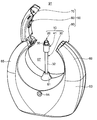
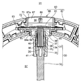
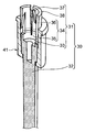
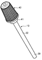
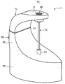
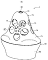
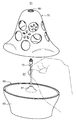
- FIG. 1 It is a perspective view of the volatilizer of 1st Embodiment of this invention. It is a perspective view of the state which the heating part holding body of the volatilizer shown in FIG. 1 is located in a separation position. It is an expanded sectional view of the upper part of a volatilizer cartridge, and a heating part. It is the cross-sectional perspective view which expanded the upper part of the core material holding body, and the clamping member. It is a sectional view of the volatilizer shown in FIG. It is a perspective view of the expanded sectional view shown in FIG. It is a perspective view in the state where a cap was attached to a volatilizer cartridge. It is a perspective view of the volatilizer of 2nd Embodiment of this invention. It is a perspective view of the volatilizer of 3rd Embodiment of this invention. It is an exploded view of the volatilizer shown in FIG.
- the volatilizer 1 in this embodiment has the volatilizer cartridge 10 as a volatilizer holder, and the container 50, and volatilizes the volatilizer of the volatilizer cartridge 10.
- FIG. 1 shows a use state of the volatilizer 1 in this embodiment. In this state, a pilot lamp 94 which will be described later is lit, and smoke (not shown) rises from above the volatilizer cartridge 10.
- FIG. 2 shows the volatilizer 1 in a state when the volatilizer cartridge 10 is replaced.
- the volatilizer cartridge 10 can be easily replaced by moving the heating unit holder 70 described later upward.
- the longitudinal direction of the volatilizer cartridge 10 is the vertical direction
- the longitudinal direction of the heating unit holder 70 is the left-right direction
- the short direction of the heating unit holder 70 is the front-rear direction.
- the volatile agent cartridge 10 includes a core material 20 impregnated with a volatile agent (not shown), a core material holder 30 that holds the core material 20, and a clamp attached to the core material holder 30. Member 41.
- the core material 20 is made of a fiber bundle of glass fibers and is impregnated with a volatilizing agent. Specifically, the volatilizing agent is held in a fine air layer formed between the fibers of the fiber bundle of the core material 20.
- the volatilizer include fragrances, deodorants, insecticides, acaricides, bactericides, and repellents. In this embodiment, fragrances are used.
- This volatilizing agent evaporates and volatilizes by being heated by the heating unit 80 described later, and is visually recognized as smoke rising from the core material 20. At the same time, the aromatic component contained in the volatilizing agent is volatilized.
- the core material holding body 30 includes a core material holding portion 31 that holds the core material 20 (not shown in the figure), and a main body portion 32 that extends below the core material holding portion 31. Have.
- the core material holding portion 31 includes a core material placement portion 33 for placing the lower end of the core material 20, and a wall portion 34 extending upward from the core material placement portion 33 so as to be disposed around the core material 20. And a protrusion 37 provided so as to protrude inwardly on the upper portion of the wall portion 34, the fiber direction of the core member 20 is directed in the vertical direction, and the upper end portion of the core member 20 is exposed.
- the core material 20 is held in the state of being made to be.
- the wall 34 rises upward from the peripheral edge of the core material mounting portion 33, and surrounds the entire periphery of the lower portion of the core material 20, and the periphery of the core material 20 from the cylindrical portion 35.
- a plurality of flexure pieces 36 extending upward are provided so as to be intermittently surrounded in the circumferential direction.
- a plurality of protrusions 37 are provided so as to protrude inward from the respective upper portions of these bending pieces 36 toward the core member 20.
- the upper end of each bending piece 36 is an abutting portion 38 that abuts a positioning portion 85 described later.
- the cylindrical portion 35 holds the core material 20 so that the fiber bundle is not scattered by surrounding the lower portion of the core material 20.
- Each bending piece 36 presses each projection 37 against the core member 20 by its own flexibility or by being sandwiched between clamping members 41 described later.
- the protrusion 37 has a contact point between the wall 34 and the core member 20 as a point contact, and a gap 40 connected to the space outside the wall 34 between the inner peripheral surface of the wall 34 and the outer peripheral surface of the core member 20. Is formed.
- the main body portion 32 has a columnar shape that is long in the vertical direction, and is provided so as to extend downward from the core material holding portion 31 so as to include the center line of the core material 20.
- a supported portion 39 supported by the support portion 61 is provided.
- the main body 32 has a shape resembling an incense stick, with the volatile agent cartridge 10 extending in the vertical direction.
- the holding member 41 has a cylindrical shape, and is inserted from below the main body portion 32 and attached to the core material holding portion 31 so as to surround the core material holding portion 31 from the outside.
- the bending piece 36 is clamped so as to be pressed against the core 20 side.
- the clamping member 41 is designed so that the inner diameter of the upper end thereof is smaller than the outer diameter of the circle defined by each of the bending pieces 36 in the mounting state where the bottom portion is located at the boundary between the core material holding portion 31 and the main body portion 32. Has been.
- the upper end of the clamping member 41 presses the projection 37 against the core material 20 via the bending piece 36, and the core material holding portion 31 is in contact with the core material 20. Is stably held.
- the main body 32 and the clamping member 41 have a shape in which a lower space 67 described later is formed around the volatile agent cartridge 10 supported by the support 61.
- the cap 42 is attached to the holding member 41 so as to cover the core member 20 from above, and suppresses volatilization of the volatilizing agent.
- the cap 42 is not illustrated in the volatilizer cartridge 10 shown in FIGS.
- the container body 50 includes a container body 60, a heating unit holder 70 that is movably attached to the container body 60, and a heating unit 80 that is held by the heating unit holder 70.
- the container body 60 includes a container lower part 63 having a support part 61, a first connection part 65 and a second connection part 66.
- the support part 61 has a cylindrical part surrounding a hole 62 penetrating in the vertical direction.
- the hole 62 opens upward, and has a diameter that allows the supported portion 39 of the main body portion 32 of the volatile agent cartridge 10 to be inserted from above.
- the support part 61 supports the volatilizer cartridge 10 while holding the inserted supported part 39.
- the container lower part 63 is located in the lower part of the container main body 60, has a support part 61 in the upper part, and accommodates the board
- the container lower part 63 has a back cover 64 that closes an opening formed in the bottom of the container lower part 63. The back cover 64 is opened and closed when the battery of the power supply unit 95 is attached or detached.
- the first connecting part 65 connects the left end of the lower part 63 and the left end of the heating part holding body 70 to support the heating part holding body 70 above the lower part 63. It has a shape that spreads outward (left side) as it goes upward from the connecting portion, and curves so as to narrow again inward (right side) at the connecting portion with the heating unit holder 70. Since the 2nd connection part 66 is a shape symmetrical with the 1st connection part 65, it abbreviate
- a lower space 67 that is a substantially cylindrical open space opened in the front-rear direction (opened on the side) is formed around the sandwiching member 41 and the main body 32. Is. In this way, the lower space 67 can be easily formed simply by specifying the shapes of the first connecting portion 65 and the second connecting portion 66.
- the lower space 67 is connected to the upper space 91 via a surrounding space 90 around the core member 20 described later.
- the heating unit holder 70 holds the heating unit 80 described later, and the left end thereof is connected to the upper end of the first connecting unit 65 by an axis extending in the front-rear direction. With this axis as the center, the right end of the heating unit holding body 70 has a locking position (the position shown in FIG. 1) locked with the upper end of the second connecting portion 66 and an open position (the position shown in FIG. 2) where it is not locked. It is possible to move between.
- a through hole penetrating in the vertical direction is provided vertically above the support 61 in the heating unit holder 70, and the volatilizer cartridge 10 is formed on the inner peripheral surface 71 surrounding the through hole so as to form the through hole.
- a heating unit holding unit 72 that holds a heating unit 80 that heats the volatilizing agent is provided.
- the heating unit 80 includes a heating element 81 as a heating element in which a conductive wire is wound in a coil shape, a base member 82 that holds the heating element 81, and a hold member 86 that is placed on the base member 82.
- the base member 82 and the hold member 86 constitute a heating element holding part as a heating element holding part that holds the heating element 81.
- the heating element 81 is formed by winding a part of a conducting wire (not shown) connected to the substrate 92 in a coil shape, and generates heat when energized to heat the volatile agent.
- a conducting wire not shown
- nichrome wire is used as the conducting wire.
- the base member 82 engages and holds the linear portions at both ends of the heating element 81 in the notches 83 provided at both ends in the left-right direction. Further, the base member 82 has a base member inner peripheral surface 84a surrounding the center member so as to form a base member opening 84 penetrating in the vertical direction, and the heating element 81 faces the base member opening 84. Is mounted on the base member 82. The base member 82 is provided with a positioning portion 85 so as to protrude from the base member inner peripheral surface 84a into the base member opening 84.
- the positioning portion 85 is provided on a surface of the base member 82 that is one step lower than the surface on which the notch 83 is formed, and comes into contact with the contact portion 38 at the upper end of the flexure piece 36, so that the front and rear of the volatilizer cartridge 10. And the position of the left-right direction and the relative position of the core material 20 and the heat generating body 81 are determined.
- the positioning portion 85 is also a portion that presses the contact portion 38 downward when the heating portion holding body 70 is positioned at the locking position.
- the vertical dimension between the lower surface of the heating element 81 and the positioning portion 85 is less than or equal to the vertical dimension between the upper end of the core member 20 and the contact portion 38 in the volatile agent cartridge 10. Designed. The design is such that when the heating part holder 70 is in the locking position with the volatilizer cartridge 10 supported by the support part 61, the heating element 81 held by the heating part holder 70 is cored. This is because the upper end of the material 20 is brought into contact.
- the core member 20 is formed of a fiber bundle and is held so that the fiber direction thereof is directed in the vertical direction, in the state where the heating unit holder 70 is in the locking position, a part of the heating element 81 is At the upper end of 20, the fibers come into contact with the gaps between the fibers.
- the heating element 81 and the core member 20 are in contact with each other, and when the heating unit holder 70 is in the open position, The heating element 81 and the core member 20 are spaced apart from each other.
- the hold member 86 is placed above the base member 82 and sandwiches the heating element 81 together with the base member 82. Similarly to the base member 82, the hold member 86 also has a hold member inner circumferential surface 87 a that surrounds the center of the hold member 86 so as to form a hold member opening 87 penetrating in the vertical direction. In addition, at both ends in the left and right direction of the hold member 86, the heating element 81 is arranged so that when the heating element 81 is pushed upward from below by the core member 20, the intermediate portion of the heating element 81 is easily displaced. Concave portions 88 that allow upward displacement of both end portions are provided.
- the shape of the holding member 86 having the recess 88 and the shape of the through hole of the heating unit holder 70 are similar to each other.
- the hold member 86 is provided with a plurality of inward ribs 89 for preventing a finger or the like from entering the hold member opening 87.
- an upper space 91 is secured in which the volatilizing agent that has evaporated to become smoke rises.
- the base member 82 and the hold member 86 which are heating element holding portions (heating body holding portions), have a base member inner peripheral surface 84a that opens the base member opening 84 and the hold member opening 87 only in the vertical direction.
- the inner peripheral surface 87a has a hollow shape, and the inner peripheral surfaces 84a and 87a define a surrounding space 90 inside thereof.
- the heating element holding part (heating element holding part) holds a heating element 81 as a heating element above the core member 20 in the peripheral space 90 inside the inner peripheral surfaces 84a and 87a.
- the heating element 81 prevents at least a part of the upper end surface of the core member 20 so as not to hinder the smooth rise of the evaporated volatile agent. Is shaped to be exposed upward.
- the lower space 67 is connected to the upper space 91 via the surrounding space 90 that is open only in the vertical direction.
- the heating element 81 is held between the base member 82 and the holding member 86, that is, in the surrounding space 90, and the high temperature portion is not exposed to the lower space 67 and the upper space 91, so There is no risk of burns when touching the heating element 81.
- the board 92 is housed in the lower part 63 of the vessel, and has a switch 93 that is pressed at the lower end of the main body 32, a pilot lamp 94, and a conductor (not shown) connected to the coiled heating element 81. .
- the switch 93 is pressed to start energization of the heating element 81.
- the switch 93 is pressed at the lower end of the main body 32 when the heating unit holder 70 is positioned at the locking position and the contact unit 38 is pressed by the positioning unit 85. Since the switch 93 has an urging force that urges the lower end of the main body portion 32 upward, the contact portion 38 is moved to the positioning portion 85 in a state where the heating portion holder 70 is located at the locking position. Can be brought into contact with each other so as to have a predetermined contact pressure. In addition, since the switch 93 has an overstroke, it is possible to absorb variations in the amount of pressing due to a molding error in the vertical direction of the core material holder 30.
- the switch 93 is not limited to being pressed at the lower end of the main body portion 32, and may be configured to be operated by an operation portion provided so as to protrude from the side surface of the main body 60.
- the pilot lamp 94 is turned on while the heating element 81 is energized, and is mounted on the substrate 92 so as to be exposed from a hole provided in front of the lower body 63.
- the substrate 92 is provided with a program that is turned off in 10 minutes after the energization of the heating element 81 is started, the pilot lamp 94 is turned off after 10 minutes.
- the power supply unit 95 applies a voltage for causing a current to flow through the heating element 81 when the switch 93 is turned on, and has a battery as a supply source of the voltage.
- the lower surface of the power supply unit 95 has an exposed shape for battery replacement, and the exposed surface is covered with a back cover 64 of the lower part 63 of the body.
- the right end of the heating unit holding body 70 is lifted upward to place the heating unit holding body 70 in an open position (a position where the heating element 81 and the core member 20 are separated). Then, the supported portion 39 of the main body portion 32 of the volatile agent cartridge 10 is inserted into the hole 62 of the support portion 61. At this time, the main body 32 has a shape that is long in the vertical direction, and the lower portion of the main body 32 is raised on the support 61, so that it is possible to embody the action of actually raising an incense stick. At this time, since the lower end of the main body portion 32 is only in contact with the switch 93 and the switch 93 is not depressed, energization of the heating element 81 has not yet started.
- the heating unit holder 70 is returned to the locking position (contact position between the heating element 81 and the core member 20).
- the positioning portion 85 of the base member 82 comes into contact with the contact portion 38 of the core material holding portion 31 to position the core material holding body 30 in the front-rear and left-right directions, and to the upper side of the switch 93.
- the abutting portion 38 is pushed downward against the urging force.
- the switch 93 is turned on, energization of the heating element 81 is started, and the pilot lamp 94 is lit.
- the core member 20 is in contact with the heating element 81 from below, and a part of the heating element 81 is in contact with the fibers while being positioned between the fibers of the core member 20.
- the energized heating element 81 generates heat and transfers heat to the fibers above the core member 20 in contact with the heating element 81.
- the upper part of the core material 20 becomes high temperature, and the volatilizing agent evaporates mainly from the high temperature contact portion to generate smoke.
- the aroma component contained in the volatilizing agent is also volatilized.
- the generated smoke rises from the surrounding space 90 where the core member 20 is located toward the upper space 91 above it. Then, when 10 minutes have elapsed from the start of energization, the energization to the heating element 81 is stopped, and the evaporation of the volatile agent is completed.
- the volatilizing agent cartridge 10 has the main body portion 32 having an outer shape extending long in the vertical direction, and thus can be shaped like an incense stick. .
- the supported portion 39 can be attached to and detached from the support portion 61 of the container 50 by grasping the main body portion 32, the volatilizing agent cartridge 10 can be easily replaced.
- the volatile agent cartridge 10 has a core material 20 containing a volatile agent that is visually recognized as smoke when evaporated on the upper end side in a state of being supported by the container body 50, and has a supported portion 39 on the lower end side.
- the support portion 61 supports the supported portion 39 below the main body portion 32 extending in the vertical direction, so that the incense stick is actually raised.
- the core material 20 is a part of the volatilizer cartridge 10 and the shape other than the core material 20 in the volatilizer cartridge 10 is determined by the core material holder 30, the length of the core material 20 and the volatilizer It is possible to adjust the usage time of the volatilizer cartridge 10 to be approximately the same as that of the incense stick, for example, only by adjusting the amount of impregnation.
- the core material 20 consists of a fiber bundle
- a volatile agent is hold
- maintenance part 31 has the cylindrical part 35, the volatile agent cartridge 10 can hold
- the heating element 81 when the heating element 81 is energized and the heating element 81 generates heat, the air existing in the surrounding space 90 around the heating element 81 and the core member 20 is heated and rises toward the upper space 91.
- the surrounding space 90 is a space that is surrounded by the base member 82 and the holding member 86 and is opened only in the vertical direction, air is supplied to the surrounding space 90 from the lower space 67 below the surrounding space 90. . That is, air is supplied from the lower space 67 to the surrounding space 90 around the heating element 81 and the core member 20, and the air is heated by the heating element 81 and travels toward the upper space 91.
- the heating element 81 when the heating element 81 is energized, an upward air flow from the lower space 67 to the upper space 91 through the surrounding space 90 is generated. Therefore, the evaporated volatile agent does not diffuse in the vicinity of the heating element 81, and can be visually recognized as smoke that rises thinly and straight like an incense stick at least immediately above the core material 20.
- the surrounding space 90 surrounded by the base member 82 and the holding member 86 has a smaller cross-sectional area in the horizontal direction than the lower space 67 and the upper space 91, so that the rising air current in the surrounding space 90 is Is larger than the flow velocity of the updraft in the lower space 67 and the flow velocity of the updraft in the upper space 91, so that the evaporated volatilizing agent is not diffused in the vicinity of the heating element 81 and at least in the portion directly above the core material 20.
- the smoke in the thin state at the time of generation can be led to the upper space 91.
- volatilizer cartridge 10 supported by the support part 61 is made into the shape in which the surrounding space 90 is formed between the container bodies 50, it passes from the lower space 67 through the surrounding space 90 to the upper space 91 reliably. Ascending airflow toward the
- the heating element 81 in the heating unit 80 has a coil shape and is held by the base member 82 so that the longitudinal direction thereof is the left-right direction, so that an intermediate portion thereof can be deflected and displaced in the vertical direction. Yes. Furthermore, since the heating part 80 can fix the position of the core material holding part 30 in the volatile agent cartridge 10 with respect to the heating part 80 by the positioning part 85, the shape of the surrounding space 90 can be made constant.
- the contact location with the heat generating body 81 in the core material 20 is made into high temperature by making the core material 20 and the heat generating body 81 contact, and volatilization agent is mainly evaporated from the contact location used as this high temperature.
- volatilization agent is mainly evaporated from the contact location used as this high temperature.
- the core member 20 is made of a fiber bundle and a part of the heating element 81 is in contact with the fiber while entering the gap between the fibers at the upper end of the core member 20, the contact area between the heating element 81 and the fiber is sufficiently large. The amount of evaporation of the volatilizer can be increased, and smoke can be clearly seen.
- the core material 20 is contacting with the heat generating body 81 from right under, the generated smoke can be raised smoothly, without being disturbed by the fiber itself.
- the heating element 81 and the upper end of the core member 20 are in contact with each other, the upper end of the core member 20 is heated to evaporate the volatilizing agent from the upper end of the core member 20.
- the gap 40 is secured between the inner peripheral surface of the wall portion 34 and the outer peripheral surface of the core member 20, air enters the lower portion of the core member 20 through the gap 40, thereby The movement of the volatilizing agent to the upper end of the core material 20 is promoted, and the volatilizing agent can be efficiently supplied to the upper end of the core material 20.
- the relative position between the core member 20 and the heating element 81 is determined by the contact between the positioning portion 85 and the contact portion 38, but the intermediate portion of the heating element 81 can be deflected upward and displaced. It is possible to absorb a dimensional error in the amount of protrusion of the core material 20 from the core material holding portion 31 when the material 20 contacts the heat generator 81 from below the heat generator 81.
- the heat generating body 81 is positioned so as to be in contact with the core member 20, the surrounding space 90 can be secured widely, and the ascending air current can be made smooth.
- volatilizer 1 of the present embodiment a plurality of volatilizer cartridges 10 having volatilizers of different fragrance components are prepared, and they are replaced to change according to the user's preference, use place, environment, and the like.
- a volatilizing agent having an aromatic component can be volatilized.
- it since it does not have the container which accommodates a liquid volatilizer like the past, there is no possibility of the liquid leakage by the fall of the volatilizer 1, etc.
- FIG. 8 shows the configuration of the volatilizer 1 according to the second embodiment of the present invention.
- the second embodiment only the parts different from the first embodiment will be described, and the description of the same configurations, operations, and effects as those in the first embodiment will be omitted.
- the difference of the volatilizer 1 of the second embodiment from the volatilizer 1 of the first embodiment is the shape of the lower space 67 due to the omission of the second connecting portion 66 of the main body 60.
- FIG. 9 and 10 show the configuration of the volatilizer 1 according to the third embodiment of the present invention.
- the third embodiment only the parts different from the first embodiment will be described, and the description of the same configuration, operation, and effect as in the first embodiment will be omitted.
- the volatilizer 1 of the third embodiment is different from the volatilizer 1 of the first embodiment in the configuration of the vessel 50. That is, the 1st connection part 65 and the 2nd connection part 66 of the volatilizer 1 in 1st Embodiment are abbreviate
- FIG. 1st connection part 65 and the 2nd connection part 66 of the volatilizer 1 in 1st Embodiment are abbreviate
- the heating part holding body 70 itself becomes a structure which can be attached or detached with respect to the container lower part 63.
- the heating unit holder 70 includes a heating unit holding unit 72 that holds the heating unit 80 in a vertically upper portion of the support unit 61, and a cylindrical unit 73 that gradually increases in diameter from the upper end to the lower end. .
- a plurality of openings 74 are provided on the side surface of the cylindrical portion 73 so that the inside and outside of the heating portion holding body 70 are communicated.
- the lower end portion of the heating part holder 70 has substantially the same shape as the upper end part of the container lower part 63, and the heating part holder 70 is supported by the support part 61 of the container lower part 63. Is connected to the lower part 63 of the vessel so as to cover.
- the heating unit holder 70 In the state where the heating unit holder 70 is connected to the lower part 63 of the volatilizer, the side of the sandwiching member 41 and the main body 32 of the volatile agent cartridge 10 is communicated with the outside of the heating unit holder 70. Is opened, and a space connected to the upper space 91 through the surrounding space 90 around the core member 20, that is, a lower space 67 is formed.
- the core material 20 is made of a fiber bundle of glass fibers
- the fibers used for the core material 20 are not limited to glass fibers.
- the core material 20 is not limited to one made of fiber such as glass fiber, but may be a porous medium or the like.
- the core material 20 containing fibers may be made of a cotton-like material whose fiber direction is not specified, or a member other than the fiber and a fiber bundle provided at the upper end of the member.
- the core material 20, the core material holding portion 31, and the main body portion 32 are each shown in a columnar shape, but these may be a prismatic shape instead of a cylindrical shape. Furthermore, the core material may be spherical or elliptical.
- the core material holding portion 31 has been described as an example including the core material placement portion 33, the wall portion 34 having the cylindrical portion 35 and the bending piece 36, and the protrusion 37. May be omitted, and a plurality of bending pieces 36 may be erected directly from the core material placement portion 33. Alternatively, the bending piece 36 and the protrusion 37 may be omitted, and the core material placement portion 33 and the cylindrical portion 35 may be included.
- a core material placement portion 33 a cylindrical body standing upright from the core material placement portion 33 so as to surround the entire circumference of the core material 20, and an inner surface of the cylinder body It may have a protrusion that protrudes intermittently in the circumferential direction so as to contact the core member 20.
- the position where the protrusion is provided may be a position where the gap 40 can be secured between the inner peripheral surface of the wall 34 or the inner peripheral surface of the cylindrical body and the outer peripheral surface of the core member 20.
- the upper part of the bending piece 36 and the upper part of the cylinder are not limited.
- the external shape of the main-body part 32 of the volatile agent cartridge 10 is made into the column shape long to an up-down direction, and the support part 61 is a hole which can insert the to-be-supported part 39 of the main-body part 32 which has a cylindrical external shape.
- the example which has 62 was shown, even if a support part has the column-shaped external shape extended upwards from the container lower part 63, and a to-be-supported part is a recessed part engaged with the column-shaped support part, Good.
- the core material holding body 30 may be omitted, and the core material 20 itself may be directly supported by the support portion 61 as a volatilizing agent cartridge extending in the vertical direction.
- the support part 61 in the container lower part 63 was shown, as a place which provides the support part 61, not only the container lower part 63 but a connection part or a heating part holding body. Moreover, the support part 61 does not necessarily need to support so that the volatile agent cartridge 10 may face an up-down direction.
- the heating element 81 in which a conducting wire is wound in a coil shape is used as the heating element.
- the heating element may be a semiconductor or a ceramic heater.
- the heating element 81 may be brought into contact.
- the holding member 41 is inserted from below the main body portion 32 to hold each bending piece 36 is shown.
- the shape is not limited to such a shape as long as the bending piece 36 can be held.
- a band or the like wound around the wall 34 may be used.
- the heating element 81 is held in the surrounding space 90 that is the inner region of the heating body holding portion has been described, but either the upper space 91 or the lower space 67 from the surrounding space 90 is shown.
- a configuration in which the heating element 81 is held so as to be somewhat exposed to the space may be employed.
- the hold member 86 may be omitted, and the rib may be provided directly on the inner peripheral surface of the heating unit holder 70.
- the heating part 80 showed about the example hold
- the heating part holding body 70 was abbreviate
- the heating element 81 may be held.
- the support portion 61 is shown as an example in which the hole 62 is fixed to the upper portion of the lower body 63 so that the hole 62 faces in the vertical direction.
- the support portion extends in the left-right direction. It may have an axis, and the hole 62 may be supported by the lower part 63 of the vessel so that the hole 62 can be rotated forward by a predetermined angle from vertically upward.
- the support part 39 is tilted forward, the supported part 39 of the volatile agent cartridge 10 is inserted into the hole 62, and the volatile agent cartridge 10 is attached to the container 50 by returning the hole 62 to be vertically upward. Is completed.
- the heating unit holder 70 and the heating unit 80 are provided with a slit through which the upper part of the volatile agent cartridge 10 can be passed, or the heating unit holder 70 is provided as described above.
- the heating element 81 needs to be held so as to be in contact with the core member 20, for example, by omitting and holding the heating element 81 at the upper end of the connecting portion. In this case, the heating element 81 comes into contact with the side surface of the core member 20.
- the heating part holding body 70 was shown about the example supported rotatably with respect to the container main body 60 by the axis
- the heating unit holding body 70 may be supported so as to be rotatable in the front-rear direction with respect to the main body 60 in the up-down direction orthogonal to the front-rear direction. Or both are connected so that either one of the upper end of the 1st connection part 65 and the left end of the heating part holding body 70 may enter in the other end part, and the heating part holding body 70 is the container main body 60. May be slidably supported.
- the thin part extended in the front-back direction is provided in a part of connection part, and the heating part 80 moves to an up-down direction by bending this thin part. It may be.
Landscapes
- Life Sciences & Earth Sciences (AREA)
- Pest Control & Pesticides (AREA)
- Health & Medical Sciences (AREA)
- General Health & Medical Sciences (AREA)
- Toxicology (AREA)
- Public Health (AREA)
- Veterinary Medicine (AREA)
- Animal Behavior & Ethology (AREA)
- Epidemiology (AREA)
- Engineering & Computer Science (AREA)
- Insects & Arthropods (AREA)
- Wood Science & Technology (AREA)
- Zoology (AREA)
- Environmental Sciences (AREA)
- Catching Or Destruction (AREA)
- Disinfection, Sterilisation Or Deodorisation Of Air (AREA)
Abstract
L'invention vise à créer une cartouche d'agent volatile dont la forme extérieure ressemble à un bâton d'encens et qui est utilisée dans un évaporateur dans lequel ladite cartouche peut être fixée de manière similaire à un bâton d'encens. A cet effet, la cartouche d'agent volatile selon l'invention est utilisée dans un évaporateur qui comprend une cartouche d'agent volatile contenant un agent volatile qui s'évapore sous l'effet de la chaleur, et un corps de dispositif présentant une partie support qui supporte la cartouche d'agent volatile et une partie chauffante qui chauffe l'agent volatile. La cartouche d'agent volatile comprend un matériau central imprégné de l'agent volatile et un corps contenant le matériau central. Le corps contenant le matériau central comporte une partie support qui contient le matériau central et une partie corps principal qui s'étend dans une direction spécifique à partir de la partie support contenant le matériau central. L'extrémité de la partie corps principal, sur la face opposée à la face où se trouve la partie support contenant le matériau central, forme une partie qui est supportée par la partie support.
Applications Claiming Priority (2)
| Application Number | Priority Date | Filing Date | Title |
|---|---|---|---|
| JP2011158348A JP5819662B2 (ja) | 2011-07-19 | 2011-07-19 | 揮散剤カートリッジ |
| JP2011-158348 | 2011-07-19 |
Publications (1)
| Publication Number | Publication Date |
|---|---|
| WO2013011991A1 true WO2013011991A1 (fr) | 2013-01-24 |
Family
ID=47558168
Family Applications (1)
| Application Number | Title | Priority Date | Filing Date |
|---|---|---|---|
| PCT/JP2012/068139 Ceased WO2013011991A1 (fr) | 2011-07-19 | 2012-07-18 | Cartouche d'agent volatile |
Country Status (2)
| Country | Link |
|---|---|
| JP (1) | JP5819662B2 (fr) |
| WO (1) | WO2013011991A1 (fr) |
Families Citing this family (3)
| Publication number | Priority date | Publication date | Assignee | Title |
|---|---|---|---|---|
| JP6280825B2 (ja) * | 2014-03-26 | 2018-02-14 | 小林製薬株式会社 | 容器 |
| JP6609416B2 (ja) * | 2015-03-31 | 2019-11-20 | 小林製薬株式会社 | 揮散器 |
| JP7269030B2 (ja) * | 2019-02-28 | 2023-05-08 | キヤノン電子株式会社 | アロマディフューザー |
Citations (3)
| Publication number | Priority date | Publication date | Assignee | Title |
|---|---|---|---|---|
| JPS59183247U (ja) * | 1983-05-23 | 1984-12-06 | 株式会社資生堂 | 芳香装置 |
| JPH0223480U (fr) * | 1988-07-29 | 1990-02-16 | ||
| JP2002272830A (ja) * | 2001-03-16 | 2002-09-24 | Keisaku Okuno | 香油蒸散器 |
Family Cites Families (2)
| Publication number | Priority date | Publication date | Assignee | Title |
|---|---|---|---|---|
| JP2578731Y2 (ja) * | 1991-06-05 | 1998-08-13 | フマキラー株式会社 | 加熱蒸散装置における薬液蒸散体 |
| JP2595028Y2 (ja) * | 1992-06-30 | 1999-05-24 | フマキラー株式会社 | 加熱蒸散装置 |
-
2011
- 2011-07-19 JP JP2011158348A patent/JP5819662B2/ja not_active Expired - Fee Related
-
2012
- 2012-07-18 WO PCT/JP2012/068139 patent/WO2013011991A1/fr not_active Ceased
Patent Citations (3)
| Publication number | Priority date | Publication date | Assignee | Title |
|---|---|---|---|---|
| JPS59183247U (ja) * | 1983-05-23 | 1984-12-06 | 株式会社資生堂 | 芳香装置 |
| JPH0223480U (fr) * | 1988-07-29 | 1990-02-16 | ||
| JP2002272830A (ja) * | 2001-03-16 | 2002-09-24 | Keisaku Okuno | 香油蒸散器 |
Also Published As
| Publication number | Publication date |
|---|---|
| JP5819662B2 (ja) | 2015-11-24 |
| JP2013022165A (ja) | 2013-02-04 |
Similar Documents
| Publication | Publication Date | Title |
|---|---|---|
| JP7157224B2 (ja) | レーザによるエアロゾル生成装置 | |
| CN101039704B (zh) | 用于扩散挥发性物质的装置 | |
| JP7275194B2 (ja) | エアロゾル生成装置 | |
| JP4824818B2 (ja) | 複数の揮発性物質を散布するための散布装置 | |
| EP2673008B1 (fr) | Élément d'émanation pour liquides volatils et son application | |
| US20170049153A1 (en) | Electronic cigarette/vaporizer and atomizer thereof | |
| BRPI0709664A2 (pt) | dispensador de material volátil | |
| US20080315005A1 (en) | Active material emitting device and method of dispensing an active material | |
| JP5819662B2 (ja) | 揮散剤カートリッジ | |
| JP5819660B2 (ja) | 揮散器 | |
| JP5819661B2 (ja) | 揮散器 | |
| JP2022511680A (ja) | 蒸気供給システム用の構成要素 | |
| JPS62164466A (ja) | 加熱型有煙蒸散器 | |
| JP2006527992A (ja) | 蒸気の放散を可能にする装置 | |
| JP2021115084A (ja) | 発香装置 | |
| JP3414584B2 (ja) | 加熱蒸散器 | |
| JP5835619B2 (ja) | 吸液芯 | |
| ES2862901T3 (es) | Dispositivo de evaporación de sustancias volátiles | |
| JP3232017U (ja) | 芳香剤容器 | |
| JP3880053B2 (ja) | 加熱蒸散器 | |
| JP2003199473A (ja) | 携帯用蚊取り器 | |
| JP2006519628A (ja) | 活性物質放出用電気的装置 | |
| JP2023163265A (ja) | アロマキャンドル | |
| JP2005229931A (ja) | 薬剤拡散装置 | |
| JPS6315956A (ja) | 蒸散器 |
Legal Events
| Date | Code | Title | Description |
|---|---|---|---|
| 121 | Ep: the epo has been informed by wipo that ep was designated in this application |
Ref document number: 12814308 Country of ref document: EP Kind code of ref document: A1 |
|
| NENP | Non-entry into the national phase |
Ref country code: DE |
|
| 122 | Ep: pct application non-entry in european phase |
Ref document number: 12814308 Country of ref document: EP Kind code of ref document: A1 |