WO2013012034A1 - 車両の制御装置 - Google Patents
車両の制御装置 Download PDFInfo
- Publication number
- WO2013012034A1 WO2013012034A1 PCT/JP2012/068329 JP2012068329W WO2013012034A1 WO 2013012034 A1 WO2013012034 A1 WO 2013012034A1 JP 2012068329 W JP2012068329 W JP 2012068329W WO 2013012034 A1 WO2013012034 A1 WO 2013012034A1
- Authority
- WO
- WIPO (PCT)
- Prior art keywords
- engine
- restart
- control
- pressure
- increase
- Prior art date
- Legal status (The legal status is an assumption and is not a legal conclusion. Google has not performed a legal analysis and makes no representation as to the accuracy of the status listed.)
- Ceased
Links
Images





Classifications
-
- B—PERFORMING OPERATIONS; TRANSPORTING
- B60—VEHICLES IN GENERAL
- B60T—VEHICLE BRAKE CONTROL SYSTEMS OR PARTS THEREOF; BRAKE CONTROL SYSTEMS OR PARTS THEREOF, IN GENERAL; ARRANGEMENT OF BRAKING ELEMENTS ON VEHICLES IN GENERAL; PORTABLE DEVICES FOR PREVENTING UNWANTED MOVEMENT OF VEHICLES; VEHICLE MODIFICATIONS TO FACILITATE COOLING OF BRAKES
- B60T7/00—Brake-action initiating means
- B60T7/12—Brake-action initiating means for automatic initiation; for initiation not subject to will of driver or passenger
-
- F—MECHANICAL ENGINEERING; LIGHTING; HEATING; WEAPONS; BLASTING
- F02—COMBUSTION ENGINES; HOT-GAS OR COMBUSTION-PRODUCT ENGINE PLANTS
- F02D—CONTROLLING COMBUSTION ENGINES
- F02D29/00—Controlling engines, such controlling being peculiar to the devices driven thereby, the devices being other than parts or accessories essential to engine operation, e.g. controlling of engines by signals external thereto
- F02D29/02—Controlling engines, such controlling being peculiar to the devices driven thereby, the devices being other than parts or accessories essential to engine operation, e.g. controlling of engines by signals external thereto peculiar to engines driving vehicles; peculiar to engines driving variable pitch propellers
-
- F—MECHANICAL ENGINEERING; LIGHTING; HEATING; WEAPONS; BLASTING
- F02—COMBUSTION ENGINES; HOT-GAS OR COMBUSTION-PRODUCT ENGINE PLANTS
- F02N—STARTING OF COMBUSTION ENGINES; STARTING AIDS FOR SUCH ENGINES, NOT OTHERWISE PROVIDED FOR
- F02N11/00—Starting of engines by means of electric motors
- F02N11/08—Circuits specially adapted for starting of engines
- F02N11/0814—Circuits specially adapted for starting of engines comprising means for controlling automatic idle-start-stop
- F02N11/0818—Conditions for starting or stopping the engine or for deactivating the idle-start-stop mode
- F02N11/0825—Conditions for starting or stopping the engine or for deactivating the idle-start-stop mode related to prevention of engine restart failure, e.g. disabling automatic stop at low battery state
-
- F—MECHANICAL ENGINEERING; LIGHTING; HEATING; WEAPONS; BLASTING
- F02—COMBUSTION ENGINES; HOT-GAS OR COMBUSTION-PRODUCT ENGINE PLANTS
- F02N—STARTING OF COMBUSTION ENGINES; STARTING AIDS FOR SUCH ENGINES, NOT OTHERWISE PROVIDED FOR
- F02N11/00—Starting of engines by means of electric motors
- F02N11/08—Circuits specially adapted for starting of engines
- F02N11/0814—Circuits specially adapted for starting of engines comprising means for controlling automatic idle-start-stop
- F02N11/0818—Conditions for starting or stopping the engine or for deactivating the idle-start-stop mode
- F02N11/0833—Vehicle conditions
- F02N11/084—State of vehicle accessories, e.g. air condition or power steering
-
- B—PERFORMING OPERATIONS; TRANSPORTING
- B60—VEHICLES IN GENERAL
- B60T—VEHICLE BRAKE CONTROL SYSTEMS OR PARTS THEREOF; BRAKE CONTROL SYSTEMS OR PARTS THEREOF, IN GENERAL; ARRANGEMENT OF BRAKING ELEMENTS ON VEHICLES IN GENERAL; PORTABLE DEVICES FOR PREVENTING UNWANTED MOVEMENT OF VEHICLES; VEHICLE MODIFICATIONS TO FACILITATE COOLING OF BRAKES
- B60T2201/00—Particular use of vehicle brake systems; Special systems using also the brakes; Special software modules within the brake system controller
- B60T2201/06—Hill holder; Start aid systems on inclined road
-
- F—MECHANICAL ENGINEERING; LIGHTING; HEATING; WEAPONS; BLASTING
- F02—COMBUSTION ENGINES; HOT-GAS OR COMBUSTION-PRODUCT ENGINE PLANTS
- F02N—STARTING OF COMBUSTION ENGINES; STARTING AIDS FOR SUCH ENGINES, NOT OTHERWISE PROVIDED FOR
- F02N2200/00—Parameters used for control of starting apparatus
- F02N2200/08—Parameters used for control of starting apparatus said parameters being related to the vehicle or its components
- F02N2200/0807—Brake booster state
-
- F—MECHANICAL ENGINEERING; LIGHTING; HEATING; WEAPONS; BLASTING
- F02—COMBUSTION ENGINES; HOT-GAS OR COMBUSTION-PRODUCT ENGINE PLANTS
- F02N—STARTING OF COMBUSTION ENGINES; STARTING AIDS FOR SUCH ENGINES, NOT OTHERWISE PROVIDED FOR
- F02N2200/00—Parameters used for control of starting apparatus
- F02N2200/08—Parameters used for control of starting apparatus said parameters being related to the vehicle or its components
- F02N2200/0809—Electrical loads
-
- Y—GENERAL TAGGING OF NEW TECHNOLOGICAL DEVELOPMENTS; GENERAL TAGGING OF CROSS-SECTIONAL TECHNOLOGIES SPANNING OVER SEVERAL SECTIONS OF THE IPC; TECHNICAL SUBJECTS COVERED BY FORMER USPC CROSS-REFERENCE ART COLLECTIONS [XRACs] AND DIGESTS
- Y02—TECHNOLOGIES OR APPLICATIONS FOR MITIGATION OR ADAPTATION AGAINST CLIMATE CHANGE
- Y02T—CLIMATE CHANGE MITIGATION TECHNOLOGIES RELATED TO TRANSPORTATION
- Y02T10/00—Road transport of goods or passengers
- Y02T10/10—Internal combustion engine [ICE] based vehicles
- Y02T10/40—Engine management systems
Definitions
- the present invention relates to a control device mounted on a vehicle having a function of automatically stopping an engine and restarting the engine automatically.
- a braking system mounted on such a vehicle is provided with a booster having a constant pressure chamber communicating with an intake manifold which generates a negative pressure when the engine is driven.
- This booster utilizes the pressure difference between the negative pressure generated in the constant pressure chamber and the atmospheric pressure (hereinafter also referred to as "booster pressure") to boost the operation force of the brake pedal by the driver.
- the negative pressure in the constant pressure chamber of the booster may approach the atmospheric pressure when the engine is stopped, for example, by the driver's fine brake operation.
- the booster pressure decreases, the operation force of the brake pedal by the driver can not be properly boosted by the booster.
- the braking force that can be applied to the wheels becomes smaller as the driver operates the brake pedal.
- the negative pressure in the constant pressure chamber is detected at predetermined intervals while the engine is automatically stopped.
- the negative pressure in the constant pressure chamber is closer to the atmospheric pressure than a preset value, it is determined that the driver can not apply a sufficient braking force to the wheels by the operation of the brake pedal.
- the braking control for increasing the braking force on the wheels is started, and the engine restart control for restarting the engine is started.
- the braking control suppresses the movement of the driver's unintended vehicle during the restart of the engine, and the engine restart control restarts the engine to recover the negative pressure in the constant pressure chamber.
- the braking control and the engine restart control are simultaneously started while the engine is stopped, the following problems occur. That is, in the braking control, a high pressure brake fluid is supplied into the wheel cylinder by operating a pump provided in the braking device, and a braking force corresponding to the brake fluid pressure in the wheel cylinder is applied to the wheel. At this time, in the braking device, the amount of power consumption increases to operate the pump. On the other hand, in the engine restart control, the starter motor is driven to perform the cranking operation. At this time, on the engine side, the amount of power consumption increases to drive the starter motor. That is, when the braking control and the engine restart control are simultaneously performed, a period in which the amount of power consumption by the vehicle becomes excessive occurs instantaneously.
- An object of the present invention is to provide a control device of a vehicle that can suppress an excessive amount of power consumption in the vehicle when restarting the engine with a decrease in negative pressure in the booster.
- the present invention increases a brake operating force by a driver by using a negative pressure (Pb) generated when driving a vehicle engine (12) to increase a booster (26).
- a brake fluid pressure (Pmc, Pwc) corresponding to the increased brake operating force is generated in the master cylinder (25) and the wheel cylinders (32a, 32b, 32c, 32d), and the wheel cylinders (32a, 32b, 32c, 32d) mounted on a vehicle having a braking device (16) for applying a braking force corresponding to the brake fluid pressure (Pwc) in the wheels (FR, FL, RR, RL), the engine (12) is automatically A control device for a vehicle for stopping or automatically restarting the engine (12), wherein the boot acquired while the engine (12) is stopped
- the negative pressure (Pb) of the engine (26) is closer to the atmospheric pressure than the restart reference value (Pbth1) set as the judgment standard of whether or not the engine (12) is to be restarted.
- the gist of the present invention is the
- the brake fluid pressure in the wheel cylinder is held and the braking force on the wheel is maintained.
- Hold control is performed to hold the That is, while the engine is being restarted, the braking force on the wheels is not reduced.
- the power consumption in the braking device is not required since the actuation of the power source to operate to increase the braking force for the wheel is not required. The amount is reduced. Therefore, when the engine is restarted with a decrease in negative pressure in the booster, it is possible to suppress an excessive amount of power consumption in the vehicle.
- the negative pressure (Pb) of the booster (26) acquired during restart of the engine (12) is a value closer to the atmospheric pressure than the restart reference value (Pbth1).
- the increase control unit (55, S28, and 28) performs increase control to increase the braking force on the wheels (FR, FL, RR, and RL) after the pressure becomes closer to the atmospheric pressure than the increase start reference value (Pbth2) set in It is preferable to further comprise S51).
- the negative pressure in the booster may gradually approach atmospheric pressure. Therefore, in the present invention, the increase control is performed when the negative pressure of the booster is closer to the atmospheric pressure than the increase start reference value, even when the holding control is performed during the restart of the engine. There is. Even if the increase control is started when the negative pressure of the booster is closer to the atmospheric pressure than the increase start reference value or after that point, the increase control is from the start of the engine restart control that restarts the engine. It also starts late. That is, there is a high possibility that the increase control is not performed at the beginning of the engine restart control that consumes the most power. Therefore, when the engine is restarted with a decrease in negative pressure in the booster, it is possible to suppress an excessive amount of power consumption in the vehicle.
- the increase control unit determines that the elapsed time (T1) after the restart of the engine (12) is started is higher than the increase control. It is preferable not to perform the increase control when it is less than the restart priority time (T1th) set so as to preferentially perform the restart of.
- the control apparatus for a vehicle acquires the change gradient ( ⁇ Pb) of the negative pressure (Pb) of the booster (26) when the engine (12) is restarted. And a time setting unit (55, S15) for setting the restart priority time (T1th) to a shorter time than when the acquired change gradient ( ⁇ Pb) is a steep gradient than when it is a steep gradient; It is preferable to further comprise
- the driver's braking operation is applied to the wheels when the gradient of the negative pressure change of the booster is steeper than when the gradient of the change is steeper than when the gradient is gradual.
- the maximum braking force that can be generated is small. Therefore, the restart priority time is set to a shorter time than when the change gradient is a slow gradient. That is, when the maximum value of the braking force that can be applied to the wheel by the driver's brake operation is small, the increase control can be started promptly.
- the control that can be applied to the wheel by the driver's brake operation is more effective when the negative pressure change gradient of the booster is slower than when the change gradient is steep.
- the maximum power is large. Therefore, the restart priority time is set to a longer time than when the change gradient is steep. As a result, it is possible to increase the probability of success in restarting the engine, as the time when the electric power stored in the battery mounted on the vehicle can be preferentially used for restarting the engine is extended.
- the increase control unit determines that an elapsed time (T1) after the restart of the engine (12) is started is the restart priority time (T1th) or more. In some cases, when the engine (12) is restarted, the increase control is not performed, while the engine (12) is not restarted, and the negative pressure (Pb) of the booster (26) is increased It is preferable to perform the increase control when the pressure is closer to the atmospheric pressure than the start reference value (Pbth2).
- the increase control is performed.
- the driving of the engine recovers the negative pressure in the booster. Therefore, since sufficient braking force can be applied to the wheels by the driver's braking operation, the increase control is not performed. Therefore, compared with the case where the increase control is performed even when the engine restart is successful, it is possible to reduce the power consumption of the vehicle at the time of the engine restart.
- the control device for a vehicle acquires the amount of electric power usable by the braking device (16) as the usable electric energy (Pa) when restarting the engine (12).
- S24, S48), and the increase control unit (55, S28, S51) can be used by the power amount acquisition unit (55, S24, S48) during restart of the engine (12).
- the electric energy (Pa) is equal to or higher than the reference electric energy (Path 1) set as the determination criterion of whether to permit the execution of the increase control, and the negative pressure (Pb) of the booster (26) is It is preferable to perform the increase control when all of the conditions closer to the atmospheric pressure than the increase start reference value (Pbth2) are satisfied.
- the increase control can be performed during the restart of the engine. Therefore, as compared with the case where the increase control is performed after the end of the engine restart control, the braking force on the wheels can be rapidly increased.
- the negative pressure (Pb) of the booster (26) acquired during restart of the engine (12) is closer to the atmospheric pressure than the increase start reference value (Pbth2).
- the speed of increase of the braking force on the wheel (FR, FL, RR, RL) based on the elapsed time (T2) until the increase control by the increase control unit (55, S28) is started.
- the control content of the increase control is set based on the elapsed time from when the negative pressure of the booster becomes closer to the atmospheric pressure than the increase start reference value and the increase control is started. .
- the increasing speed is set to a higher speed when the elapsed time is longer than when it is short.
- the increase amount is set based on the elapsed time, the increase amount is set to be longer when the elapsed time is long than when it is short.
- the increase control is performed, the braking force on the wheel is increased based on the set content (at least one of the increase speed and the increase amount).
- the increase control unit (55, S28, S51) can be used by the power amount acquisition unit (55, S24, S48) acquired during the restart of the engine (12).
- the power amount (Pa) is less than the reference power amount (Path 1), it is preferable not to perform the increase control.
- the increase control is performed even if the negative pressure of the booster approaches the atmospheric pressure than the increase start reference value. It does not happen. Therefore, an increase in the amount of power consumption in the vehicle can be suppressed. Even in such a case, the increase control may be performed when the engine restart control ends and the available power amount returns to the reference power amount or more.
- FIG. 1 is a block diagram showing a braking system in a first embodiment.
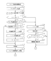
- 5 is a flowchart (first half) illustrating an engine restart braking process routine according to the first embodiment.
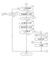
- 6 is a flowchart (second half part) illustrating an engine restart braking process routine according to the first embodiment. 6 is a timing chart showing changes in booster pressure, engine speed, battery voltage, detection signal of a brake switch, and brake hydraulic pressure in restarting the engine in the first embodiment.
- FIG. 6 is a timing chart showing changes in booster pressure, engine speed, battery voltage, detection signal of a brake switch, and brake hydraulic pressure in restarting the engine in the first embodiment.
- 6 is a timing chart showing changes in booster pressure, engine speed, battery voltage, detection signal of a brake switch, and brake hydraulic pressure in restarting the engine in the first embodiment.
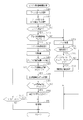
- the flowchart which demonstrates the engine restart damping
- FIG. 10 is a timing chart showing changes in booster pressure, engine speed, battery voltage, detection signal of a brake switch, and brake hydraulic pressure in restarting the engine in the second embodiment.
- FIG. 10 is a timing chart showing changes in booster pressure, engine speed, battery voltage, detection signal of a brake switch, and brake hydraulic pressure in restarting the engine in the second embodiment.
- First Embodiment A first embodiment of the present invention will be described below with reference to FIGS. 1 to 7.
- the traveling direction (forward direction) of the vehicle will be described as the front (vehicle front).
- the vehicle according to the present embodiment automatically stops the engine according to the establishment of a predetermined stop condition during traveling of the vehicle in order to improve the fuel efficiency performance and the emission performance, and then the engine according to the establishment of the predetermined start condition Has a so-called idle stop function that automatically restarts the Therefore, in this vehicle, the engine is automatically stopped during deceleration or stop by the driver's brake operation.
- the front wheels FR, FL are drive wheels. It is a so-called front wheel drive car that functions as In such a vehicle, a driving force generator 13 having an engine 12 that generates a driving force corresponding to the amount of operation of the accelerator pedal 11 by the driver, and the driving force generated by the driving force generator 13 And a driving force transmission device 14 for transmitting. Further, the vehicle is provided with a braking device 16 for applying a braking force corresponding to the operation force of the brake pedal 15 by the driver, that is, the brake operation force to each of the wheels FR, FL, RR, and RL.
- the driving force generation device 13 is provided with a fuel injection device (not shown) which is disposed in the vicinity of an intake port (not shown) of the engine 12 and has an injector for injecting fuel to the engine 12.
- the driving force generator 13 is driven based on control of an engine ECU 17 (also referred to as an “engine electronic control device”) having a CPU, a ROM, a RAM, and the like (not shown).
- the engine ECU 17 includes an accelerator opening sensor SE1 for outputting to the engine ECU 17 a detection signal corresponding to an operation amount of the accelerator pedal 11 by the driver, ie, an accelerator opening, and a rotational speed of the engine 12 (hereinafter referred to as “engine And a rotational speed sensor SE2 that outputs a detection signal corresponding to the rotational speed to the engine ECU 17 is electrically connected. Then, the engine ECU 17 calculates the accelerator opening degree and the engine rotational speed based on the detection signals from the respective sensors SE1 and SE2, and controls the driving force generation device 13 based on the calculated accelerator opening degree and the engine rotational speed. .
- the driving force transmission device 14 controls the automatic transmission 18, the differential gear 19 for appropriately distributing the driving force transmitted from the output shaft of the automatic transmission 18 and transmitting it to the front wheels FR and FL, and the automatic transmission 18 And an AT ECU (not shown).
- the automatic transmission 18 includes a hydraulic drive power transmission mechanism 20 having a torque converter 20 a as an example of a fluid coupling, and a transmission mechanism 21.
- the braking device 16 includes a hydraulic pressure generating device 28 having a master cylinder 25, a booster 26 and a reservoir 27, and a brake actuator 31 having two hydraulic circuits 29, 30 (in FIG. 2). (Indicated by a two-dot chain line).
- the respective hydraulic circuits 29, 30 are connected to the master cylinder 25 of the hydraulic pressure generating device 28, respectively.
- a wheel cylinder 32a for the right front wheel FR and a wheel cylinder 32d for the left rear wheel RL are connected to the first hydraulic circuit 29, and a wheel for the left front wheel FL is connected to the second hydraulic circuit 30.
- a cylinder 32b and a wheel cylinder 32c for the right rear wheel RR are connected.
- the booster 26 is connected to an intake manifold (not shown) that generates negative pressure when the engine 12 is driven. Then, the booster 26 boosts (increases) the brake operation force by the driver using the pressure difference between the negative pressure generated in the intake manifold and the atmospheric pressure.
- boost pressure the pressure difference between the negative pressure generated in the intake manifold and the atmospheric pressure
- the booster pressure becomes smaller as the negative pressure generated in the intake manifold approaches atmospheric pressure.
- the vehicle of the present embodiment is provided with a booster pressure sensor SE3 for detecting a booster pressure generated by the booster 26.
- a detection signal corresponding to the negative pressure generated in the intake manifold is output from the booster pressure sensor SE3 to a brake ECU 55 described later.
- Master cylinder 25 generates a brake fluid pressure corresponding to the brake operating force by the driver.
- the brake fluid pressure generated by the master cylinder 25 is a fluid pressure corresponding to the brake operating force by the driver boosted by the booster 26.
- the brake fluid is supplied from the master cylinder 25 into the wheel cylinders 32a to 32d via the hydraulic circuits 29, 30 based on the internally generated brake hydraulic pressure.
- a braking force corresponding to the brake fluid pressure in the wheel cylinders 32a to 32d is applied to the wheels FR, FL, RR, and RL.
- the brake fluid pressure in the master cylinder 25 is referred to as "master cylinder pressure”
- the brake fluid pressure in the wheel cylinders 32a to 32d is referred to as "wheel cylinder pressure”.
- each hydraulic circuit 29, 30 is connected to the master cylinder 25 via connection paths 33, 34, and the connection paths 33, 34 are normally open linear solenoid valves (difference Pressure adjustment valves) 35a and 35b are respectively provided.
- the linear solenoid valves 35a and 35b include a valve seat, a valve body, an electromagnetic coil, and a biasing member (eg, a coil spring) for biasing the valve body away from the valve seat, and the valve body is for a brake It displaces according to the current value supplied to an electromagnetic coil from ECU55. That is, when the brake pedal 15 is operated, the wheel cylinder pressure in the wheel cylinders 32a to 32d is maintained at a hydraulic pressure corresponding to the value of the current supplied to the linear solenoid valves 35a, 35b.
- connection paths 33 and 34 are provided with check valves 60a and 60b arranged in parallel with the linear solenoid valves 35a and 35b. These check valves 60a and 60b restrict the flow of brake fluid from the wheel cylinders 32a to 32d to the master cylinder 25 while permitting the flow of brake fluid from the master cylinder 25 to the wheel cylinders 32a to 32d.
- One-way valve is provided.
- connection paths 33 and 34 and the paths 36a to 36d constitute a flow path connecting the master cylinder 25 and the wheel cylinders 32a to 32d.
- pressure increasing valves 37a, 37b, 37c, and 37d which are normally open solenoid valves that operate when regulating the pressure increase of the wheel cylinder pressure in the wheel cylinders 32a to 32d, are arranged in the paths 36a to 36d.
- Pressure reducing valves 38a, 38b, 38c and 38d which are normally closed solenoid valves that operate when the pressure is reduced, are provided.
- reservoirs 39, 40 for temporarily storing the brake fluid which has flowed out from the wheel cylinders 32a-32d via the pressure reducing valves 38a-38d, and a pump operated based on the rotation of the motor 41. 42 and 43 are connected.
- the reservoirs 39 and 40 are connected to the pumps 42 and 43 through the suction flow channels 44 and 45, and connected to the connection paths 33 and 34 through the master flow channels 46 and 47 more than the linear solenoid valves 35a and 35b. It is connected to the master cylinder 25 side.
- the pumps 42 and 43 are connected to connection portions 50 and 51 between the pressure increasing valves 37a to 37d and the linear solenoid valves 35a and 35b in the hydraulic circuits 29 and 30 through the supply flow paths 48 and 49, respectively. There is. Then, when the motor 41 is rotated, the pumps 42 and 43 suck the brake fluid from the reservoirs 39 and 40 and the master cylinder 25 through the suction flow paths 44 and 45 and the master side flow paths 46 and 47, The brake fluid is discharged into the supply channels 48, 49.
- brake ECU 55 also referred to as “brake electronic control device” that controls the drive of the brake actuator 31 will be described.
- a rotation speed sensor SE ⁇ b> 2 and a booster pressure sensor SE ⁇ b> 3 are electrically connected to the input side interface of the brake ECU 55 as an example of a control device for a vehicle.
- wheel speed sensors SE4, SE5, SE6, SE7 for detecting the wheel speeds of the respective wheels FR, FL, RR, RL and an acceleration sensor for detecting the acceleration in the longitudinal direction of the vehicle in the input side interface (Also referred to as "G sensor”) SE8 is electrically connected to a brake switch SW1 for detecting whether the brake pedal 15 is operated.
- the acceleration sensor SE8 outputs a signal that gives a positive value when the vehicle stops on an uphill road, and outputs a signal that gives a negative value when the vehicle stops on a downhill road Be done.
- valves 35a, 35b, 37a to 37d, 38a to 38d and the motor 41 are electrically connected to the output side interface of the brake ECU 55. Furthermore, the brake ECU 55 can transmit and receive various types of information via the bus 56 and each ECU such as the engine ECU 17.
- the brake ECU 55 is a digital computer including a CPU, a ROM, and a RAM (not shown), a valve driver circuit (not shown) for operating the valves 35a, 35b, 37a to 37d and 38a to 38d, and a motor 41. (Not shown) for driving the motor.
- Various control processes (such as engine restart braking process described later) and various threshold values are stored in advance in the ROM of the digital computer.
- the RAM stores various types of information that can be appropriately rewritten.
- the engine restart braking process routine of the present embodiment is a process routine that sets the execution timing of the braking control (holding control, increase control) based on the booster pressure when restarting the engine 12.
- the engine restart braking process routine is a process routine executed every predetermined period (for example, 10 milliseconds) set in advance.
- the brake ECU 55 calculates the booster pressure Pb based on the detection signal from the booster pressure sensor SE3 (step S10). Subsequently, the brake ECU 55 obtains a change gradient ⁇ Pb of the booster pressure Pb by performing time differentiation on the calculated booster pressure Pb. Therefore, in the present embodiment, the brake ECU 55 also functions as a change gradient acquisition unit.
- And ECU55 for brakes determines whether engine 12 is stopping from engine-speed Ne (refer FIG. 5) detected based on the detection signal from rotation speed sensor SE2 (step S12). For example, when the engine rotational speed Ne is less than a reference value Neth (see FIG. 5) set to a value slightly smaller than the engine rotational speed at the time of idling, the brake ECU 55 assumes that the engine 12 is stopping. judge. In step S12, the brake ECU 55 requests the engine ECU 17 for information for specifying the state of the engine 12, and the engine 12 is stopped based on the information received from the engine ECU 17 as a response to the request. It may be determined whether or not the restart of the engine 12 has failed.
- step S12 NO
- step S12: NO the brake ECU 55 determines that the engine 12 is in operation or restart of the engine 12 is successful, and shifts the process to step S30 described later.
- step S12: YES the brake ECU 55 determines that the engine 12 has not been restarted or is being restarted.
- step S13 the brake ECU 55 determines whether the booster pressure Pb calculated in step S10 is less than a preset restart reference value Pbth1 (step S13).
- the booster pressure Pb approaches the atmospheric pressure, the maximum value of the braking force that can be applied to each of the wheels FR, FL, RR, and RL by the brake operation by the driver decreases. Therefore, when the booster pressure Pb approaches the atmospheric pressure, it is preferable to restart the engine 12 to recover the booster pressure Pb.
- restart reference value Pbth1 is set as a judgment standard of a start for making engine 12 restart.
- step S13: NO If the booster pressure Pb is equal to or greater than the restart reference value Pbth1 (step S13: NO), the brake ECU 55 applies a sufficiently large braking force to the wheels FR, FL, RR, and RL by the driver's brake operation. It is determined that the process can be performed, and the process proceeds to step S30 described later.
- step S13: YES when the booster pressure Pb is less than the restart reference value Pbth1 (step S13: YES), the brake ECU 55 applies a sufficient braking force to the wheels FR, FL, RR, and RL by the brake operation by the driver. It is determined that the restart request flag FLG1 is off (step S14).
- the restart request flag FLG1 is a flag for specifying whether the engine ECU 17 has already been requested to restart the engine 12 or not.
- step S14: NO When the restart request flag FLG1 is on (step S14: NO), the brake ECU 55 has requested the engine ECU 17 to restart the engine 12, so the process proceeds to step S18 described later.
- step S14: YES when the restart request flag FLG1 is off (step S14: YES), the brake ECU 55 controls the electric power stored in the battery (not shown) mounted on the vehicle more than the braking control by the braking device 16 A restart priority time T1th is set which specifies a period to be preferentially used in the restart control in step S15.
- the restart priority time T1th is set to a larger value in the case where the change gradient ⁇ Pb of the booster pressure calculated in step S11 is a steep gradient than in the case of a gentle gradient.
- the brake ECU 55 determines that the change gradient ⁇ Pb is a steep gradient, and the preset reference priority time (For example, 3 seconds).
- the reference priority time is a minimum time or it is assumed that the engine 12 can be successfully restarted when sufficient power is supplied to a starter motor (not shown) included in the driving force generator 13.
- the time is set to be slightly longer than the time.
- the brake ECU 55 determines that the change gradient ⁇ Pb is a gentle gradient, and a margin value preset for the reference priority time. It sets to the value which added (for example, 2 seconds). Therefore, in the present embodiment, the brake ECU 55 also functions as a time setting unit.
- the brake ECU 55 requests the engine ECU 17 to restart the engine 12 (step S16). At this time, the brake ECU 55 also transmits information for specifying the restart priority time T1th set in step S15 to the engine ECU 17. Then, the brake ECU 55 sets the restart request flag FLG1 on (step S17), and then shifts the process to the next step S18.
- step S18 the brake ECU 55 performs holding control to hold the braking force on each of the wheels FR, FL, RR, and RL. Specifically, the brake ECU 55 operates the linear solenoid valves 35a and 35b to hold the wheel cylinder pressures of the wheel cylinders 32a to 32d. At this time, the brake ECU 55 closes the linear solenoid valves 35a and 35b. Therefore, in the present embodiment, the brake ECU 55 also functions as a holding control unit. Then, ECU55 for brakes transfers to step S19 which mentions the process later.
- the booster pressure Pb is equal to or higher than the restart reference value Pbth1, and the brake switch SW1 is on, so the automatic stop state of the engine 12 is maintained. Thereafter, with the brake switch SW1 turned on, when the booster pressure Pb gradually approaches the atmospheric pressure, the master cylinder pressure Pmc and the wheel cylinder pressure Pwc are reduced so as to follow the booster pressure Pb. Then, at the second timing t12 when the booster pressure Pb becomes less than the restart reference value Pbth1, the restart condition of the engine 12 is satisfied, and thus the starter motor starts driving to restart the engine 12.
- the driving time of the starter motor at this time is the restart priority time T1th set by the brake ECU 55. That is, the engine 12 performs the cranking operation until the restart priority time T1th elapses from the second timing t12.
- the holding control is started, and the braking forces on the respective wheels FR, FL, RR, and RL are held by the braking forces at that time.
- the linear solenoid valves 35a and 35b are in the closed state. Therefore, while the holding control is being performed after the second timing t12, the wheel cylinder pressure Pwc of each of the wheel cylinders 32a to 32d is maintained regardless of the change in the booster pressure Pb and the change in the brake operating force by the driver. Be pressed.
- the master cylinder pressure Pmc of the master cylinder 25 changes along with the change of the booster pressure Pb even if the brake operation force by the driver does not change.
- the linear solenoid valves 35a and 35b may not be completely closed due to an assembly error or the like at the time of manufacture.
- the wheel cylinder pressure Pwc is gradually reduced even when holding control is performed, that is, the braking force on the wheels FR, FL, RR, and RL is gradually reduced. It is also possible. However, even if the braking force gradually decreases, the decreasing speed becomes a very small value as compared with the case where the linear solenoid valves 35a and 35b are in the open state.
- step S19 the brake ECU 55 detects the remaining charge amount Pz of the battery.
- the brake ECU 55 determines whether the booster pressure Pb calculated in step S10 is less than a predetermined pressure start reference value (increase start reference value) Pbth2 (step S20).
- the pressurization start reference value Pbth2 is set to a value smaller than the restart reference value Pbth1, that is, a value close to the atmospheric pressure.
- step S20 If the booster pressure Pb is less than the pressurization start reference value Pbth2 (step S20: YES), the brake ECU 55 controls the wheels FR, FL, RR, and RL only by the driver's brake operation due to the decrease of the booster pressure Pb. It is determined that sufficient braking force can not be applied. And ECU55 for brakes acquires restart elapsed time T1 as elapsed time after restart of the engine 12 is started (step S21).
- the restart elapsed time T1 of the present embodiment is a time when the restart of the engine 12 is requested, that is, an elapsed time from the time when the process of step S16 is performed.
- the brake ECU 55 determines whether the acquired restart elapsed time T1 is equal to or greater than the restart priority time T1th set in step S15 (step S22). If the restart elapsed time T1 is equal to or greater than the restart priority time T1th, the brake ECU 55 determines that the restart of the engine 12 has failed. That is, in the present embodiment, when the determination result in step S22 is YES before the determination result in step S12 is YES, it is determined that the restart of the engine 12 has failed. If the restart elapsed time T1 is equal to or greater than the restart priority time T1th (step S22: YES), the brake ECU 55 shifts the process to step S26 described later.
- step S22 when the restart elapsed time T1 is less than the restart priority time T1th (step S22: NO), the brake ECU 55 determines that the booster pressure Pb has become less than the pressurization start reference value Pbth2 as the elapsed time from the present time
- the pressurization waiting time T2 is acquired (step S23).
- the acquisition of the pressurization standby time T2 is stopped when the increase control is started. That is, when the increase control is started, the pressurization standby time T2 is held by an elapsed time from when the booster pressure Pb becomes less than the pressurization start reference value Pbth2 until the increase control is started.
- the brake ECU 55 acquires the usable electric energy Pa usable by the braking device 16 based on the remaining charge amount Pz detected in step S19 (step S24).
- the brake ECU 55 sets a value obtained by subtracting a preset setting value Ps from the detected remaining charge amount Pz as the usable power amount Pa.
- the set value Ps is set to a value slightly larger than the amount of electric power assumed for use other than the restart of the engine 12 and the braking control in the braking device 16 during the restart of the engine 12 There is. Therefore, in the present embodiment, the brake ECU 55 also functions as an electric energy acquisition unit.
- the brake ECU 55 determines whether the acquired available power amount Pa is less than a preset reference power amount Path 1 (step S25).
- the reference power amount Path1 is set as a determination reference of whether or not a preset specified voltage value can be applied to the motor 41 of the braking device 16 in order to increase the wheel cylinder pressure Pwc. It is a value. If the available electric energy Pa is less than the reference electric energy Path 1 (step S25: YES), the brake ECU 55 prohibits the execution of the increase control for increasing the braking force on the wheels FR, FL, RR, and RL The engine restart braking process routine is temporarily ended. On the other hand, when the available power amount Pa is equal to or greater than the reference power amount Path 1 (step S25: NO), the brake ECU 55 shifts the process to the next step S26.
- step S26 the brake ECU 55 sets the pressurization flag FLG2 to ON. Subsequently, the brake ECU 55 sets a pressure condition for performing the increase control based on the pressure standby time T2 acquired in step S23 (step S27).
- the application speed of the wheel cylinder pressure Pwc i.e., the increase speed of the braking force to the wheels FR, FL, RR, and RL
- the application quantity of the wheel cylinder pressure Pwc i.e., the increase quantity of the braking force
- the pressurizing speed is set to be higher when the pressurizing standby time T2 is longer than when it is short, and the pressurizing amount is shorter than when the pressurizing standby time T2 is long. It is set too much. Therefore, in the present embodiment, the brake ECU 55 also functions as a control content setting unit. Then, ECU55 for brakes transfers the process to following step S28.
- step S28 the brake ECU 55 performs the increase control based on the pressure condition (pressure speed and pressure amount) set in step S27. Specifically, the brake ECU 55 maintains the operating state (that is, the closed state) of the linear solenoid valves 35a and 35b that were in operation by execution of the holding control, while the motor 41 (that is, the pumps 42 and 43) Activate.
- the control mode of the motor 41 at this time is a mode according to the set pressure condition. Therefore, in the present embodiment, the brake ECU 55 also functions as an increase control unit. Thereafter, the brake ECU 55 temporarily terminates the engine restart braking process routine.
- step S29 determines whether the pressurization flag FLG2 is on (step S29). That is, in step S29, it is determined whether or not the increase control is being executed. If the pressurization flag FLG2 is on (step S29: YES), the brake ECU 55 shifts the process to step S28 described above. On the other hand, when the pressurization flag FLG2 is off (step S29: NO), the brake ECU 55 once ends the engine restart braking process routine.
- step S30 the brake ECU 55 performs a reset process to turn off the flags FLG1 and FLG2 and reset the restart elapsed time T1 and the pressurization standby time T2 to "0 (zero)". Subsequently, the brake ECU 55 determines whether the braking control is being performed by the braking device 16, that is, whether the holding control or the increase control is being performed (step S31). When the braking control is not being performed (step S31: NO), the brake ECU 55 temporarily ends the engine restart braking process routine.
- step S31 when braking control is in progress (step S31: YES), the brake ECU 55 performs the first condition that the booster pressure Pb calculated in step S10 exceeds the restart reference value Pbth1 or the brake switch SW1 is off. It is determined whether a second condition of being present is satisfied (step S32).
- the first condition and the second condition are conditions for ending the braking control. That is, in step S32, it is determined whether the braking control termination condition is satisfied.
- step S32: NO when the termination condition of the braking control is not satisfied (step S32: NO), since both the first condition and the second condition are not satisfied, the braking ECU 55 performs the engine restart braking processing routine. It will end once.
- step S32: YES when the termination condition of the braking control is satisfied (step S32: YES), the brake ECU 55 performs the releasing process of the braking control because the first condition or the second condition is satisfied (step S33). That is, when the holding control is being performed, the brake ECU 55 gradually reduces the amount of power supplied to the linear solenoid valves 35a and 35b, and finally sets the amount of power to "0 (zero)".
- the brake ECU 55 temporarily terminates the engine restart braking process routine.
- the timing chart shown in FIG. 5 shows a case where the restart of the engine 12 is successful and the restartable amount of the engine 12 is successful that the available power amount Pa is less than the reference power amount Path1. Further, in the timing chart shown in FIG. 6, when the restart of the engine 12 fails and the available power amount Pa is less than the reference power amount Path 1 while the restart elapsed time T1 is less than the restart priority time T1th. Is shown. Furthermore, in the timing chart shown in FIG. 7, when the restart of the engine 12 is successful and the available power amount Pa becomes equal to or greater than the reference power amount Path 1 while the restart elapsed time T1 is less than the restart priority time T1th. Is shown.
- the electric power stored in the battery (hereinafter also referred to as "battery electric power Pig") is It fluctuates according to the amount of power supplied to the starter motor.
- the power consumption amount Pm of the starter motor becomes maximum at the third timing t13 at which the drive starts, for example, due to the inrush current at the time of start-up and the inertial resistance of the engine rotating unit (crankshaft etc.).
- the power consumption Pm does not exceed the power consumption at the third timing t13.
- the booster pressure Pb becomes less than the pressurization start reference value Pbth2.
- the restart elapsed time T1 which is an elapsed time after the restart of the engine 12 is started, is less than the restart priority time T1th, and the available power amount Pa is It is less than the reference power amount Path1. Therefore, the battery power Pig is preferentially used for restarting the engine 12 over the increase control. As a result, sufficient power is supplied to the starter motor.
- the booster pressure Pb becomes equal to or higher than the restart reference value Pbth1.
- holding pressure control is ended and the wheel cylinder pressure Pwc is gradually reduced.
- the wheel cylinder pressure Pwc becomes a fluid pressure corresponding to the brake operation force by the driver. That is, the wheel cylinder pressure Pwc is substantially equal to the master cylinder pressure Pmc (eighth timing t18).
- the brake switch SW1 is turned off at the subsequent ninth timing t19, the master cylinder pressure Pmc and the wheel cylinder pressure Pwc are reduced. As a result, no braking force from the braking device 16 is applied to the wheels FR, FL, RR, and RL.
- the first timing t21 before the restart and retention control of the engine 12 is started is the same as that of the timing chart shown in FIG. 5, and hence the description prior to the first timing t21 is omitted. .
- the restart of the engine 12 fails. Then, when the booster pressure Pb becomes less than the pressurization start reference value Pbth2 at the second timing t22 after that, the measurement of the pressurization standby time T2 is started. At this point, the restart control is not started because the restart elapsed time T1 is less than the restart priority time T1th and the available power amount Pa is less than the reference power amount Path1.
- the process for restarting the engine 12 is temporarily ended.
- the booster pressure Pb since the restart of the engine 12 has failed, the booster pressure Pb remains below the pressurization start reference value Pbth2. Therefore, the pressurizing speed and the pressurizing amount Pup of the wheel cylinder pressure Pwc are set in accordance with the pressurizing standby time T2, which is the time from the second timing t22 to the third timing t23.
- the braking control is changed from the holding control to the increase control.
- execution of the increase control causes the wheel cylinder pressure Pwc to be pressurized, which in turn increases the braking force applied to the wheels FR, FL, RR, and RL.
- the power supply to the starter motor for restarting the engine 12 is stopped. Therefore, the battery power Pig is a sufficient amount of power to cause the braking device 16 to perform the increase control. As a result, appropriate increase control is performed based on the set pressure speed and the pressure amount Pup. In the increase control, when the wheel cylinder pressure Pwc is pressurized by the set pressurization amount Pup, the operation of the pumps 42 and 43 is stopped.
- restart and retention control of the engine 12 is started. Then, when the booster pressure Pb becomes less than the pressurization start reference value Pbth2 at the second timing t32 thereafter, measurement of the pressurization waiting time T2 is started. At this point, the restart control is not started because the restart elapsed time T1 is less than the restart priority time T1th and the available power amount Pa is less than the reference power amount Path1.
- the available electric energy Pa is the reference electric energy although the process of restarting the engine 12 is continuously performed. It becomes Path 1 or more. That is, the battery stores a sufficient amount of power for causing the braking device 16 to perform the increase control even while power is supplied to the starter motor. Further, at the third timing t33, it is not determined that the restart of the engine 12 is successful because the engine speed Ne is less than the reference value Neth. Therefore, at the third timing t33, the braking control is changed from the holding control to the increase control.
- the pressurizing speed and the pressurizing amount Pup of the wheel cylinder pressure Pwc are set in accordance with the pressurizing standby time T2 which is the time from the second timing t32 to the third timing t33. Then, by execution of the increase control, the wheel cylinder pressure Pwc is pressurized, and thus the braking force on each of the wheels FR, FL, RR, and RL is increased.
- the braking device 16 performs holding control. That is, while the engine 12 is being restarted, the braking forces on the wheels FR, FL, RR, and RL are not reduced. Moreover, in the holding control, compared with the case where the increase control of increasing the wheel cylinder pressure Pwc to increase the braking force to the wheels FR, FL, RR, and RL is performed, the braking device is not used because the pumps 42 and 43 are not operated. Power consumption at 16 is reduced. Therefore, when the engine 12 is restarted with the decrease of the booster pressure Pb, it is possible to suppress an excessive amount of power consumption in the vehicle.
- the booster pressure Pb may gradually approach the atmospheric pressure. Therefore, in the present embodiment, even when the holding control is performed during the restart of the engine 12, if the booster pressure Pb is closer to the atmospheric pressure than the pressurization start reference value Pbth2, the increase control is performed. It may be done. In this case, the increase control is started late from the start of the process of restarting the engine 12. That is, the increase control is not performed at the initial stage (for example, between the first timing t31 and the second timing t32 shown in FIG. 7) which consumes the most power in the engine restart control. Therefore, when the engine 12 is restarted with the decrease of the booster pressure Pb, it is possible to suppress an excessive amount of power consumption in the vehicle.
- the maximum value of the braking force that can be applied to RR and RL is small. Therefore, the restart priority time T1th is set to a shorter time when the change gradient ⁇ Pb is steep than when it is gentle. As a result, quick increase control can be performed.
- an elapsed time from when the booster pressure Pb becomes closer to the atmospheric pressure than the pressurization start reference value Pbth2 until the increase control is started ie, pressurization is performed
- the pumps 42 and 43 are controlled based on the control content (pressing speed and pressing amount Pup) set based on the waiting time T2). For example, when it is desired to quickly increase the braking force, the pressurizing speed is set to a high speed and the pressurizing amount Pup is set to a relatively large value. Therefore, when the vehicle is stopped on a slope, the occurrence of unintended vehicle movement (so-called slip) caused by a decrease in booster pressure Pb can be suppressed or the amount of movement can be reduced. .
- the pressurizing speed is set to a low speed and the pressurizing amount Pup is set to a smaller value. Therefore, compared to the case where the control content is constant regardless of the pressurization standby time T2, it is possible to reduce the amount of power consumption in the braking device 16 accompanying the increase control.
- the distribution of the battery power Pig is adjusted such that the process of restarting the engine 12 and the increase control do not overlap in time, or even if they overlap, the overlap period becomes as short as possible. . Therefore, in a vehicle equipped with a battery with a relatively small storage capacity, restarting the engine 12 and braking control can be appropriately performed by executing the engine restart braking process routine.
- restarting the engine 12 and braking control can be appropriately performed by executing the engine restart braking process routine.
- the engine restart braking process routine in a vehicle equipped with a battery with a relatively large storage capacity, it is possible to avoid that the time when the power consumption amount in the vehicle becomes excessive is instantaneously generated. .
- step S42 the brake ECU 55 sequentially executes the processes of steps S40, S41, and S42 that are equivalent to the above-described steps S10, S11, and S12.
- step S42 NO
- the brake ECU 55 shifts the process to step S53 described later.
- step S43 the brake ECU 55 determines whether the booster pressure Pb calculated in step S40 is less than the restart reference value Pbth1 (step S43).
- step S43: NO If the booster pressure Pb is equal to or higher than the restart reference value Pbth1 (step S43: NO), the brake ECU 55 shifts the process to step S53 described later. On the other hand, when the booster pressure Pb is less than the restart reference value Pbth1 (step S43: YES), the brake ECU 55 requests the engine ECU 17 to restart the engine 12 (step S44). Subsequently, the brake ECU 55 performs holding control (step S45), and detects the remaining charge amount Pz of the battery (step S46). Therefore, in the present embodiment, the brake ECU 55 also functions as a holding control unit.
- step S47: YES the brake ECU 55 acquires the usable electric energy Pa (step S47). S48). Then, when the acquired available electric energy Pa is equal to or greater than the reference electric energy Path 1 (step S 49: YES), the brake ECU 55 sets the pressurization flag FLG 2 on (step S 50), and performs increase control (step S 50) S51), the engine restart braking process routine is temporarily ended. Therefore, in the present embodiment, the brake ECU 55 also functions as an increase control unit.
- step S49: NO the brake ECU 55 temporarily ends the engine restart braking process routine without performing the increase control.
- step S47: NO when the booster pressure Pb is equal to or higher than the pressurization start reference value Pbth2 (step S47: NO), when the pressurization flag FLG2 is on (step S52: YES), the brake ECU 55 increases. Control is performed (step S51), and the engine restart braking process routine is temporarily ended. Further, even if the determination result in step S47 is NO, when the pressurization flag FLG2 is off (step S52: NO), the brake ECU 55 once ends the engine restart braking process routine.
- step S53 the brake ECU 55 performs the same reset process as step S30. And ECU55 for brakes performs each process of step S54, S55, S56 equivalent to each process of said step S31, S32, S33, and once complete
- the timing chart shown in FIG. 9 shows the case where the restart of the engine 12 is successful.
- the booster pressure Pb is less than the restart reference value Pbth1, and the brake switch SW1 remains on. Therefore, the increase control is continued.
- the brake switch SW1 is turned off at the subsequent fourth timing t44, the increase control is ended. Then, the wheel cylinder pressure Pwc is reduced, and as a result, the braking force from the braking device 16 is not applied to the wheels FR, FL, RR, and RL.
- the time period in which the restart of the engine 12 and the increase control overlap in time is longer than in the first embodiment.
- the engine restart braking process routine is preferably performed by a vehicle equipped with a battery with a relatively large storage capacity. That is, since the increase control is promptly started during the restart of the engine 12, the occurrence of the unintended vehicle movement of the driver can be suppressed during the restart of the engine 12, or the movement amount can be reduced as much as possible. .
- the increase control may be performed whenever the booster pressure Pb approaches the atmospheric pressure than the pressurization start reference value Pbth2 during the restart of the engine 12.
- the available power amount Pa is less than the reference power amount Path1
- the pressurizing speed of the wheel cylinder pressure Pwc is slower when the available power amount Pa is smaller than when it is large.
- the wheels FR and FL can be swiftly compared to the case where the increase control is not performed until the process of restarting the engine 12 is completed. , RR and RL can be increased. Moreover, the pumps 42 and 43 at this time are controlled such that the amount of power consumption by the braking device 16 does not exceed the usable amount of power Pa. Therefore, the braking force on the wheels FR, FL, RR, and RL can be increased while suppressing an excessive amount of power consumption in the vehicle.
- the braking control is changed from the increase control to the holding control. You may In addition, when it is determined that the restart of the engine 12 is successful, the braking control itself may be ended. Even with this configuration, since the booster pressure Pb is recovered by the successful restart of the engine 12, the brake fluid pressure increased by the driver's brake operation force is in the open state at the end of control. It is transmitted to the wheel cylinders 32a to 32d through the valves 35a, 35b, and is transmitted to the wheel cylinders 32a to 32d through check valves 60a, 60b provided in parallel with the linear solenoid valves 35a, 35b during holding control. . As a result, it is possible to apply sufficient braking force to the wheels FR, FL, RR, and RL.
- the pressurization amount Pup of the wheel cylinder pressure Pwc is increased when the pressurization standby time T2 is long. While setting is larger than in the short case, the pressurizing speed may be set to a constant value regardless of the length of the pressurizing standby time T2.
- the pressurization speed of the wheel cylinder pressure Pwc is increased when the pressurization standby time T2 is long.
- the pressurizing amount Pup may be set to a constant value regardless of the length of the pressurizing standby time T2 while setting the speed to a higher speed than in the case of a short time.
- the pressurization speed and the pressurization amount Pup of the wheel cylinder pressure Pwc are set to the pressurization standby time. It may be a constant value regardless of the length of T2.
- the booster pressure Pb is less than the pressurization start reference value Pbth2 during the restart of the engine 12, the available power amount Pa is less than the reference power amount Path1, and the engine 12 is restarted. If it is not determined that the start has been successful yet, increase control is performed to operate the pumps 42 and 43 within the range where the amount of power consumption by the braking device 16 does not exceed the available power amount Pa. It is also good. In this case, the pressurizing speed of the wheel cylinder pressure Pwc is higher as the available power amount Pa at that time is larger.
- the braking control is changed from the holding control to the increase control regardless of the success or failure of the restart of the engine 12 You may
- the restart priority time T1th may be a smaller value as the booster pressure change gradient ⁇ Pb is larger.
- the restart priority time T1th may be set using a linear function or a quadratic function with the change gradient ⁇ Pb as a parameter.
- the restart priority time T1th is never set to less than the reference priority time.
- the margin value may be set to a larger value as the difference between the change gradient ⁇ Pb of the booster pressure and the reference gradient value is larger.
- the restart priority time T1th may be a constant value regardless of the change pressure ⁇ Pb of the booster pressure.
- the execution of the increase control may be prohibited regardless of the amount of the usable power amount Pa.
- the brake ECU 55 requests the engine ECU 17 to restart the engine 12, from the timing when the brake ECU 55 receives information from the engine ECU 17 that processing for restarting the engine 12 has started.
- the elapsed time of may be taken as the restart elapsed time T1.
- the pressurizing speed may be set to a higher speed when the value of the wheel speed or the wheel acceleration is large than when the value is small.
- the pressurization amount Pup may be set to a larger value when the value of the wheel speed or the wheel acceleration is large than that when the value is small.
- At the time of performing the increase control at least one of the pressing speed of the wheel cylinder pressure Pwc and the pressing amount Pup may be changed according to the gradient of the road surface on which the vehicle is positioned.
- the pressing speed may be set to a higher speed when the slope of the road surface is steep than when it is gentle.
- the pressurization amount Pup may be set to a larger value when the slope of the road surface is a steep slope than when the slope is a slow slope.
- the first method is a time-differentiated value of the vehicle speed calculated based on detection signals from the wheel speed sensors SE4 to SE7 (also referred to as “vehicle speed derivative value”), and a detection signal from the acceleration sensor SE8.
- the difference with the acceleration also referred to as “G sensor value”
- the second method is a method of acquiring gradient information from an information processing device (for example, a navigation device) mounted on a vehicle.
- restart reference value Pbth1 and the pressurization start reference value Pbth2 may be set to larger values when the slope of the road surface where the vehicle is located is steep than when the slope is steep. .
- the electric parking brake when the electric parking brake is mounted on the vehicle, the electric parking brake may be used to increase the braking force on the wheels when the increase control is performed.
- both the brake actuator 31 and the electric parking brake may be operated, or the brake actuator 31 may not be operated.
- the electronic control unit that controls the electric parking brake functions as an increase control unit.
- the increase control unit (55, S28, S51)
- the available power (Pa) acquired by the power acquisition unit (55, S24, S48) during restart of the engine (12) is less than the reference power (Path 1);
- Pb negative pressure
- the braking device (16) is driven in a range in which the power consumption of the braking device (16) does not exceed the available power (Pa) acquired by the power acquisition unit (55, S24, S48)
- the control apparatus for a vehicle according to claim 6, wherein the increase control is performed.
- the braking system when the negative pressure of the booster is closer to the atmospheric pressure than the increase start reference value when the available power amount acquired during engine restart is less than the reference power amount, the braking system The braking force on the wheels is increased as long as the power consumption of the vehicle does not exceed the available power. Therefore, it is possible to increase the braking force on the wheels while suppressing excessive power consumption in the vehicle.
- the power acquisition unit acquires the power of the battery mounted on the vehicle as the remaining power (Pz), and the available power (Pa) is obtained based on the remaining power (Pz).
- the control device of the vehicle characterized by acquiring.
- the braking device (16) is a difference between the brake fluid pressure (Pmc) in the master cylinder (25) and the brake fluid pressure (Pwc) in the wheel cylinders (32a, 32b, 32c, 32d)
- a differential pressure control valve (35a, 35b) that operates to adjust the pressure
- a pump (42, 43) that operates to supply brake fluid into the wheel cylinders (32a, 32b, 32c, 32d)
- the holding control holds the inside of the wheel cylinder (32a, 32b, 32c, 32d) by operating the differential pressure adjusting valve (35a, 35b)
- the increase control is characterized in that the pressure in the wheel cylinder (32a, 32b, 32c, 32d) is increased by operating both the differential pressure adjusting valve (35a, 35b) and the pump (42, 43). Control device for vehicles.
Landscapes
- Engineering & Computer Science (AREA)
- Mechanical Engineering (AREA)
- Chemical & Material Sciences (AREA)
- Combustion & Propulsion (AREA)
- General Engineering & Computer Science (AREA)
- Transportation (AREA)
- Control Of Vehicle Engines Or Engines For Specific Uses (AREA)
- Regulating Braking Force (AREA)
- Valves And Accessory Devices For Braking Systems (AREA)
Abstract
ブレーキ用ECUは、エンジンの停止中に演算したブースタ圧(Pb)が、エンジンを再始動させるか否かの判断基準として設定された再始動基準値(Pbth1)よりも大気圧に近づいたことによりエンジンが再始動される場合に、ホイールシリンダのホイールシリンダ圧(Pwc)を保圧させることにより、車輪に対する制動力を保持させる保持制御を行う(第2のタイミングt12)。
Description
本発明は、エンジンを自動的に停止させたり、エンジンを自動的に再始動させたりする機能を有する車両に搭載される制御装置に関する。
近年、車両の燃費向上などを目的として、車両の停止中又は停止直前にエンジンを自動的に停止させると共に、運転者による発進操作を契機にエンジンを自動的に再始動させる所謂アイドルストップ機能を有する車両の開発が進められている(特許文献1参照)。こうした車両に搭載される制動装置には、エンジン駆動時に負圧が発生するインテークマニホールドに連通する定圧室を有するブースタが設けられている。このブースタは、定圧室内に発生する負圧と大気圧との圧力差(以下、「ブースタ圧」ともいう。)を利用し、運転手によるブレーキペダルの操作力を倍力するものである。
ところで、ブースタの定圧室内の負圧は、運転手による細やかなブレーキ操作などにより、エンジンの停止時に大気圧に近づくことがある。このようにブースタ圧が小さくなると、運転手によるブレーキペダルの操作力がブースタによって適切に倍力されなくなる。その結果、運転手によるブレーキペダルの操作によって車輪に付与できる制動力が小さくなっていく。
そのため、特許文献1に記載の制御装置では、エンジンの自動停止中に、定圧室内の負圧が所定周期毎に検出される。そして、定圧室内の負圧が予め設定された設定値よりも大気圧に近くなった場合には、運転手によるブレーキペダルの操作によって十分な制動力を車輪に付与できないと判断する。すると、車輪に対する制動力を増大させるための制動制御が開始されると共に、エンジンを再始動させるためのエンジン再始動制御が開始される。その結果、制動制御によってエンジンの再始動中における運転手の意図しない車両の移動が抑制されると共に、エンジン再始動制御によってエンジンが再始動されることにより定圧室内の負圧が回復される。
ところで、エンジンの停止中に上記制動制御とエンジン再始動制御とが同時に開始されると、以下に示す問題が発生する。すなわち、制動制御では、制動装置に設けられるポンプを作動させることによりホイールシリンダ内に高圧のブレーキ液が供給され、該ホイールシリンダ内のブレーキ液圧に応じた制動力が車輪に付与される。この際、制動装置では、ポンプを作動させるために消費電力量が多くなる。一方、エンジン再始動制御では、スタータモータが駆動され、クランキング動作が行われる。この際、エンジン側では、スタータモータを駆動させるために消費電力量が多くなる。つまり、上記制動制御及びエンジン再始動制御を同時に行わせると、車両での電力消費量が過大となる期間が瞬間的に生じてしまう。
本発明の目的は、ブースタ内の負圧低下に伴ってエンジンを再始動させる場合に、車両での電力消費量が過大となることを抑制できる車両の制御装置を提供することにある。
上記目的を達成するために、本発明は、運転手によるブレーキ操作力を、車両のエンジン(12)の駆動時に発生する負圧(Pb)を利用してブースタ(26)が増大させることにより、マスタシリンダ(25)及びホイールシリンダ(32a,32b,32c,32d)内に増大後のブレーキ操作力に応じたブレーキ液圧(Pmc、Pwc)を発生させ、該ホイールシリンダ(32a,32b,32c,32d)内のブレーキ液圧(Pwc)に応じた制動力を車輪(FR,FL,RR,RL)に付与する制動装置(16)を有する車両に搭載され、前記エンジン(12)を自動的に停止させたり、前記エンジン(12)を自動的に再始動させたりするための車両の制御装置であって、前記エンジン(12)の停止中に取得された前記ブースタ(26)の負圧(Pb)が、前記エンジン(12)を再始動させるか否かの判断基準として設定された再始動基準値(Pbth1)よりも大気圧に近づいたことにより前記エンジン(12)が再始動される場合に、前記車輪(FR,FL,RR,RL)に対する制動力を保持させる保持制御を行う保持制御部(55、S18、S45)を備えることを要旨とする。
上記構成によれば、ブースタの負圧が再始動基準値よりも大気圧に近づいたことを契機にエンジンの再始動が行われると、ホイールシリンダ内のブレーキ液圧を保圧して車輪に対する制動力を保持させる保持制御が行われる。つまり、エンジンを再始動させている間では、車輪に対する制動力が減少されない。しかも、保持制御では、車輪に対する制動力を増大させる増大制御が行われる場合と比較して、車輪に対する制動力を増大させるべく作動する動力源の作動を必要としない分、制動装置での電力消費量が少なくなる。したがって、ブースタ内の負圧低下に伴ってエンジンを再始動させる場合に、車両での電力消費量が過大となることを抑制できる。
本発明の車両の制御装置は、前記エンジン(12)の再始動中に取得された前記ブースタ(26)の負圧(Pb)が、前記再始動基準値(Pbth1)よりも大気圧に近い値に設定された増大開始基準値(Pbth2)よりも大気圧に近くなってから、前記車輪(FR,FL,RR,RL)に対する制動力を増大させる増大制御を行う増大制御部(55、S28、S51)をさらに備えることが好ましい。
エンジンの再始動中であっても、ブースタ内の負圧が徐々に大気圧に近づいていくこともある。そこで、本発明では、エンジンの再始動中に保持制御が行われる場合であっても、ブースタの負圧が増大開始基準値よりも大気圧に近くなった場合には、増大制御が行われることがある。ブースタの負圧が増大開始基準値よりも大気圧に近くなった時点又は該時点以降に増大制御が開始されたとしても、該増大制御は、エンジンを再始動させるエンジン再始動制御の開始時点よりも遅れて開始される。つまり、エンジン再始動制御において最も電力を消費する初期では、増大制御が行われない可能性が高い。したがって、ブースタ内の負圧低下に伴ってエンジンを再始動させる場合に、車両での電力消費量が過大となることを抑制できる。
本発明の車両の制御装置において、前記増大制御部(55、S28)は、前記エンジン(12)の再始動が開始されてからの経過時間(T1)が、前記増大制御よりも前記エンジン(12)の再始動を優先的に行わせるために設定された再始動優先時間(T1th)未満である場合には、前記増大制御を行わないことが好ましい。
上記構成によれば、ブースタの負圧が再始動基準値よりも大気圧に近づいたことを契機にエンジンの再始動が開始されてからの経過時間が再始動優先時間未満である場合には、車輪に対する制動力を増大させることよりも、エンジンを再始動させること、即ちブースタ内の負圧を回復させることが優先的に行われる。そのため、エンジン再始動制御と増大制御との時間的な重複を避けることができる、又は重複する期間を短くすることができる。
本発明の車両の制御装置は、前記エンジン(12)が再始動される際に前記ブースタ(26)の負圧(Pb)の変化勾配(ΔPb)を取得する変化勾配取得部(55、S11)と、取得された変化勾配(ΔPb)が急勾配である場合には緩勾配である場合よりも、前記再始動優先時間(T1th)を短い時間に設定する時間設定部(55、S15)と、をさらに備えることが好ましい。
上記構成によれば、エンジンの再始動中においては、ブースタの負圧の変化勾配が急勾配である場合のほうが、変化勾配が緩勾配である場合よりも、運転手によるブレーキ操作によって車輪に付与できる制動力の最大値が小さい。そのため、再始動優先時間は、変化勾配が緩勾配である場合よりも短い時間に設定される。つまり、運転手によるブレーキ操作によって車輪に付与できる制動力の最大値が小さい場合には、増大制御を速やかに開始させることが可能となる。
その一方で、エンジンの再始動中においては、ブースタの負圧の変化勾配が緩勾配である場合のほうが、変化勾配が急勾配である場合よりも、運転手によるブレーキ操作によって車輪に付与できる制動力の最大値が大きい。そのため、再始動優先時間は、変化勾配が急勾配である場合よりも長い時間に設定される。その結果、車両に搭載されるバッテリに蓄電される電力をエンジンの再始動に優先的に使用できる時間が長くなる分、エンジンの再始動の成功確率を高くすることができる。
本発明の車両の制御装置において、前記増大制御部(55、S28)は、前記エンジン(12)の再始動が開始されてからの経過時間(T1)が前記再始動優先時間(T1th)以上である場合において、前記エンジン(12)が再始動したときには前記増大制御を行わない一方で、前記エンジン(12)が再始動していないと共に、前記ブースタ(26)の負圧(Pb)が前記増大開始基準値(Pbth2)よりも大気圧に近いときには前記増大制御を行うことが好ましい。
上記構成によれば、エンジンの再始動が失敗した場合には、ブースタ内の負圧が回復しないため、増大制御が行われる。その一方で、エンジンの再始動が成功した場合には、エンジンの駆動によってブースタ内の負圧が回復する。そのため、運転手によるブレーキ操作によって、車輪に対して十分な制動力を付与することができることから、増大制御を行わない。したがって、エンジンの再始動が成功した場合にも増大制御が行われる場合と比較して、エンジンの再始動時における車両での電力消費量を少なくすることができる。
本発明の車両の制御装置は、前記エンジン(12)を再始動させる場合に、前記制動装置(16)で使用可能な電力量を使用可能電力量(Pa)として取得する電力量取得部(55、S24、S48)をさらに備え、前記増大制御部(55、S28、S51)は、前記エンジン(12)の再始動中に前記電力量取得部(55、S24、S48)によって取得された使用可能電力量(Pa)が、前記増大制御の実行を許可するか否かの判定基準として設定された基準電力量(Path1)以上であること、及び、前記ブースタ(26)の負圧(Pb)が前記増大開始基準値(Pbth2)よりも大気圧に近いこと、が全て成立した場合に、前記増大制御を行うことが好ましい。
上記構成によれば、エンジン再始動制御の実行中であっても、取得された使用可能電力量が基準電力量以上である場合には、増大制御を行っても、車両に搭載されるバッテリの蓄電量不足にはならないと判断される。つまり、増大制御を行うのに十分な電力残量が車載のバッテリにある場合には、エンジンの再始動中に増大制御を行うことができる。そのため、エンジン再始動制御の終了後から増大制御を行う場合と比較して、車輪に対する制動力を速やかに増大させることができる。
本発明の車両の制御装置は、前記エンジン(12)の再始動中に取得された前記ブースタ(26)の負圧(Pb)が前記増大開始基準値(Pbth2)よりも大気圧に近い値になってから、前記増大制御部(55、S28)による前記増大制御が開始されるまでの経過時間(T2)に基づいて、前記車輪(FR,FL,RR,RL)に対する制動力の増大速度及び増大量のうち少なくとも一方を設定する制御内容設定部(55、S27)をさらに備え、前記増大制御部(55、S28)は、前記増大制御を行う場合には、前記制御内容設定部(55、S27)によって設定された内容に基づき前記制動装置(16)を制御することが好ましい。
上記構成によれば、ブースタの負圧が増大開始基準値よりも大気圧に近い値になってから増大制御が開始されるまでの経過時間に基づいて、当該増大制御の制御内容が設定される。例えば、経過時間に基づいて増大速度を設定する場合、増大速度は、経過時間が長い場合には短い場合よりも高速度に設定される。また、経過時間に基づいて増大量を設定する場合、増大量は、経過時間が長い場合には短い場合よりも多めに設定される。そして、増大制御を行う場合には、設定された内容(増大速度及び増大量の少なくとも一方)に基づき車輪に対する制動力が増大される。
本発明の車両の制御装置において、前記増大制御部(55、S28、S51)は、前記エンジン(12)の再始動中に前記電力量取得部(55、S24、S48)によって取得された使用可能電力量(Pa)が前記基準電力量(Path1)未満である場合には、前記増大制御を行わないことが好ましい。
上記構成によれば、エンジンの再始動中に取得された使用可能電力量が基準電力量未満である場合には、ブースタの負圧が増大開始基準値よりも大気圧に近づいても増大制御が行われない。そのため、車両での消費電力量の増大を抑制することができる。なお、こうした場合でも、エンジン再始動制御が終了し、使用可能電力量が基準電力量以上に戻った場合には、増大制御が行われることもある。
なお、本発明をわかりやすく説明するために実施形態を示す図面の符号に対応づけて説明したが、本発明が実施形態に限定されるものではないことは言うまでもない。
(第1の実施形態)
以下、本発明を具体化した第1の実施形態を図1~図7に従って説明する。なお、以下における本明細書中の説明においては、車両の進行方向(前進方向)を前方(車両前方)として説明する。
以下、本発明を具体化した第1の実施形態を図1~図7に従って説明する。なお、以下における本明細書中の説明においては、車両の進行方向(前進方向)を前方(車両前方)として説明する。
本実施形態の車両は、燃費性能やエミッション性能を向上させるべく、車両走行中に所定の停止条件の成立に応じてエンジンを自動的に停止させ、その後、所定の始動条件の成立に応じてエンジンを自動的に再始動させる所謂アイドルストップ機能を有している。そのため、この車両では、運転手によるブレーキ操作による減速中又は停車中に、エンジンが自動的に停止される。
次に、アイドルストップ機能を有する車両の一例について説明する。
図1に示すように、車両は、複数(本実施形態では4つ)ある車輪(右前輪FR、左前輪FL、右後輪RR及び左後輪RL)のうち、前輪FR,FLが駆動輪として機能する所謂前輪駆動車である。こうした車両には、運転手によるアクセルペダル11の操作量に応じた駆動力を発生するエンジン12を有する駆動力発生装置13と、該駆動力発生装置13で発生した駆動力を前輪FR,FLに伝達する駆動力伝達装置14とを備えている。また、車両には、運転手によるブレーキペダル15の操作力、即ちブレーキ操作力に応じた制動力を各車輪FR,FL,RR,RLに付与するための制動装置16が設けられている。
駆動力発生装置13は、エンジン12の吸気ポート(図示略)近傍に配置され、且つ該エンジン12に燃料を噴射するインジェクタを有する燃料噴射装置(図示略)を備えている。こうした駆動力発生装置13は、図示しないCPU、ROM及びRAMなどを有するエンジン用ECU17(「エンジン用電子制御装置」ともいう。)の制御に基づき駆動する。このエンジン用ECU17には、運転手によるアクセルペダル11の操作量、即ちアクセル開度に応じた検出信号をエンジン用ECU17に出力するアクセル開度センサSE1と、エンジン12の回転数(以下、「エンジン回転数」ともいう。)に応じた検出信号をエンジン用ECU17に出力する回転数センサSE2とが電気的に接続されている。そして、エンジン用ECU17は、各センサSE1,SE2からの検出信号に基づきアクセル開度及びエンジン回転数を演算し、該演算したアクセル開度及びエンジン回転数などに基づき駆動力発生装置13を制御する。
駆動力伝達装置14は、自動変速機18と、該自動変速機18の出力軸から伝達された駆動力を適宜配分して前輪FR,FLに伝達するディファレンシャルギヤ19と、自動変速機18を制御する図示しないAT用ECUとを備えている。自動変速機18は、流体継手の一例としてのトルクコンバータ20aを有する流体式駆動力伝達機構20と、変速機構21とを備えている。
制動装置16は、図1及び図2に示すように、マスタシリンダ25、ブースタ26及びリザーバ27を有する液圧発生装置28と、2つの液圧回路29,30を有するブレーキアクチュエータ31(図2では二点鎖線で示す。)とを備えている。各液圧回路29,30は、液圧発生装置28のマスタシリンダ25にそれぞれ接続されている。そして、第1液圧回路29には、右前輪FR用のホイールシリンダ32a及び左後輪RL用のホイールシリンダ32dが接続されると共に、第2液圧回路30には、左前輪FL用のホイールシリンダ32b及び右後輪RR用のホイールシリンダ32cが接続されている。
液圧発生装置28においてブースタ26は、エンジン12の駆動時に負圧が発生する図示しないインテークマニホールドに接続されている。そして、ブースタ26は、インテークマニホールド内に発生する負圧と大気圧との圧力差を利用し、運転手によるブレーキ操作力を倍力(増大)する。なお、本実施形態では、「インテークマニホールド内に発生する負圧と大気圧との圧力差」のことを「ブースタ圧」という。このブースタ圧は、インテークマニホールド内に発生する負圧が大気圧に近づくほど小さな値となる。
本実施形態の車両には、ブースタ26で発生したブースタ圧を検出するためのブースタ圧センサSE3が設けられている。このブースタ圧センサSE3からは、インテークマニホールド内に発生した負圧に応じた検出信号が後述するブレーキ用ECU55に出力される。
マスタシリンダ25は、運転手によるブレーキ操作力に応じたブレーキ液圧を発生する。マスタシリンダ25で発生するブレーキ液圧は、ブースタ26によって倍力された運転手によるブレーキ操作力に応じた液圧である。そして、マスタシリンダ25からは、内部で発生したブレーキ液圧に基づき、ブレーキ液が液圧回路29,30を介してホイールシリンダ32a~32d内に供給される。すると、車輪FR,FL,RR,RLには、ホイールシリンダ32a~32d内のブレーキ液圧に応じた制動力が付与される。なお、本実施形態では、マスタシリンダ25内のブレーキ液圧を「マスタシリンダ圧」というと共に、ホイールシリンダ32a~32d内のブレーキ液圧を「ホイールシリンダ圧」という。
ブレーキアクチュエータ31において各液圧回路29,30は、連結経路33,34を介してマスタシリンダ25にそれぞれ接続されており、該各連結経路33,34には、常開型のリニア電磁弁(差圧調整弁)35a,35bがそれぞれ設けられている。リニア電磁弁35a,35bは、弁座、弁体、電磁コイル及び弁体を弁座から離間する方向に付勢する付勢部材(例えば、コイルスプリング)を備えており、弁体は、ブレーキ用ECU55から電磁コイルに供給される電流値に応じて変位する。すなわち、ブレーキペダル15が操作される場合、ホイールシリンダ32a~32d内のホイールシリンダ圧は、リニア電磁弁35a,35bに供給される電流値に応じた液圧で維持される。
また、連結経路33,34には、リニア電磁弁35a,35bと並列となるように配置されたチェック弁60a,60bが設けられている。これらチェック弁60a,60bは、ホイールシリンダ32a~32d側からマスタシリンダ25側へのブレーキ液の流動を規制する一方で、マスタシリンダ25側からホイールシリンダ32a~32d側へのブレーキ液の流動を許容する一方向弁である。
第1液圧回路29には、ホイールシリンダ32aに接続される右前輪用経路36aと、ホイールシリンダ32dに接続される左後輪用経路36dとが形成されている。また、第2液圧回路30には、ホイールシリンダ32bに接続される左前輪用経路36bと、ホイールシリンダ32cに接続される右後輪用経路36cとが形成されている。したがって、本実施形態では、連結経路33,34及び各経路36a~36dにより、マスタシリンダ25とホイールシリンダ32a~32dとを連結する流路が構成される。また、経路36a~36dには、ホイールシリンダ32a~32d内のホイールシリンダ圧の増圧を規制する際に作動する常開型の電磁弁である増圧弁37a,37b,37c,37dと、ホイールシリンダ圧を減圧させる際に作動する常閉型の電磁弁である減圧弁38a,38b,38c,38dとが設けられている。
また、液圧回路29,30には、ホイールシリンダ32a~32dから減圧弁38a~38dを介して流出したブレーキ液を一時貯留するためのリザーバ39,40と、モータ41の回転に基づき作動するポンプ42,43とが接続されている。リザーバ39,40は、吸入用流路44,45を介してポンプ42,43に接続されると共に、マスタ側流路46,47を介して連結経路33,34においてリニア電磁弁35a,35bよりもマスタシリンダ25側に接続されている。また、ポンプ42,43は、供給用流路48,49を介して液圧回路29,30における増圧弁37a~37dとリニア電磁弁35a,35bとの間の接続部位50,51に接続されている。そして、ポンプ42,43は、モータ41が回転した場合に、リザーバ39,40及びマスタシリンダ25側から吸入用流路44,45及びマスタ側流路46,47を介してブレーキ液を吸引し、該ブレーキ液を供給用流路48,49内に吐出する。
次に、ブレーキアクチュエータ31の駆動を制御するブレーキ用ECU55(「ブレーキ用電子制御装置」ともいう。)について説明する。
図2に示すように、車両の制御装置の一例としてのブレーキ用ECU55の入力側インターフェースには、回転数センサSE2及びブースタ圧センサSE3が電気的に接続されている。また、入力側インターフェースには、各車輪FR,FL,RR,RLの車輪速度を検出するための車輪速度センサSE4,SE5,SE6,SE7と、車両の前後方向における加速度を検出するための加速度センサ(「Gセンサ」ともいう。)SE8と、ブレーキペダル15が操作されているか否かを検出するためのブレーキスイッチSW1とが電気的に接続されている。なお、加速度センサSE8からは、車両が登坂路で停車する際に正の値となるような信号が出力される一方、車両が降坂路で停車する際に負の値となるような信号が出力される。
また、ブレーキ用ECU55の出力側インターフェースには、各弁35a,35b,37a~37d,38a~38d及びモータ41などが電気的に接続されている。さらに、ブレーキ用ECU55は、エンジン用ECU17などの各ECUとバス56を介して各種情報の送受信が可能となっている。
また、ブレーキ用ECU55は、図示しないCPU、ROM及びRAMなどから構成されるデジタルコンピュータ、各弁35a,35b,37a~37d,38a~38dを作動させるための図示しない弁用ドライバ回路、及びモータ41を作動させるための図示しないモータ用ドライバ回路を有している。デジタルコンピュータのROMには、各種制御処理(後述するエンジン再始動時制動処理等)及び各種閾値などが予め記憶されている。また、RAMには、車両の図示しないイグニッションスイッチがオンである間、適宜書き換えられる各種の情報などがそれぞれ記憶される。
次に、本実施形態のブレーキ用ECU55が実行する各種制御処理ルーチンのうち、自動停止されたエンジン12を再始動させる際に実行するエンジン再始動時制動処理ルーチンについて、図3及び図4に示すフローチャートと、図5に示すタイミングチャートとを参照して説明する。本実施形態のエンジン再始動時制動処理ルーチンは、エンジン12を再始動させる際におけるブースタ圧に基づき、制動制御(保持制御、増大制御)の実行タイミングを設定する処理ルーチンである。
さて、エンジン再始動時制動処理ルーチンは、予め設定された所定周期毎(例えば、10ミリ秒)に実行される処理ルーチンである。このエンジン再始動時制動処理ルーチンにおいて、ブレーキ用ECU55は、ブースタ圧センサSE3からの検出信号に基づきブースタ圧Pbを演算する(ステップS10)。続いて、ブレーキ用ECU55は、演算したブースタ圧Pbに対して時間微分することにより、ブースタ圧Pbの変化勾配ΔPbを取得する。したがって、本実施形態では、ブレーキ用ECU55が、変化勾配取得部としても機能する。
そして、ブレーキ用ECU55は、回転数センサSE2からの検出信号に基づき検出したエンジン回転数Ne(図5参照)から、エンジン12が停止中であるか否かを判定する(ステップS12)。例えば、ブレーキ用ECU55は、エンジン回転数Neが、アイドル時のエンジン回転数よりも僅かに小さい値に設定された基準値Neth(図5参照)未満である場合にエンジン12が停止中であると判定する。また、ステップS12では、ブレーキ用ECU55は、エンジン用ECU17に対してエンジン12の状態を特定するための情報を要求し、該要求の返答としてエンジン用ECU17から受信した情報に基づきエンジン12が停止中であるか否か、又はエンジン12の再始動が失敗したか否かを判定してもよい。
エンジン12が停止中ではない場合(ステップS12:NO)、ブレーキ用ECU55は、エンジン12が駆動中又はエンジン12の再始動が成功したと判断し、その処理を後述するステップS30に移行する。一方、エンジン12が停止中である場合(ステップS12:YES)、ブレーキ用ECU55は、エンジン12の再始動がなされていない、又は再始動中であると判断する。そして、ブレーキ用ECU55は、ステップS10で演算したブースタ圧Pbが予め設定された再始動基準値Pbth1未満であるか否かを判定する(ステップS13)。ブースタ圧Pbが大気圧に近づくほど、運転手によるブレーキ操作によって各車輪FR,FL,RR,RLに付与できる制動力の最大値が小さくなる。そのため、ブースタ圧Pbが大気圧に近づいた場合には、エンジン12を再始動させて、ブースタ圧Pbを回復させることが好ましい。そこで、本実施形態では、エンジン12を再始動させるための開始の判断基準として、再始動基準値Pbth1が設定されている。
ブースタ圧Pbが再始動基準値Pbth1以上である場合(ステップS13:NO)、ブレーキ用ECU55は、運転手によるブレーキ操作によって、車輪FR,FL,RR,RLに対して十分に大きな制動力を付与できると判断し、その処理を後述するステップS30に移行する。一方、ブースタ圧Pbが再始動基準値Pbth1未満である場合(ステップS13:YES)、ブレーキ用ECU55は、運転手によるブレーキ操作によって車輪FR,FL,RR,RLに対して十分な制動力を付与できないと判断し、再始動要求フラグFLG1がオフであるか否かを判定する(ステップS14)。この再始動要求フラグFLG1は、エンジン12の再始動をエンジン用ECU17に既に要求したか否かを特定するためのフラグである。
再始動要求フラグFLG1がオンである場合(ステップS14:NO)、ブレーキ用ECU55は、エンジン用ECU17にエンジン12の再始動を要求済みであるため、その処理を後述するステップS18に移行する。一方、再始動要求フラグFLG1がオフである場合(ステップS14:YES)、ブレーキ用ECU55は、車両に搭載される図示しないバッテリに蓄電される電力を、制動装置16での制動制御よりもエンジン12の再始動制御で優先的に使用させる期間を特定する再始動優先時間T1thを設定する(ステップS15)。
本実施形態では、再始動優先時間T1thは、ステップS11で演算したブースタ圧の変化勾配ΔPbが急勾配である場合には緩勾配である場合よりも大きな値に設定される。具体的には、ブレーキ用ECU55は、ブースタ圧の変化勾配ΔPbが予め設定された基準勾配値以上である場合には、変化勾配ΔPbが急勾配であると判断し、予め設定された基準優先時間(例えば、3秒)に設定する。この基準優先時間は、駆動力発生装置13が備える図示しないスタータモータに対して十分な電力が供給される場合に、エンジン12の再始動を成功させることができると想定される最低限度の時間又は該時間よりも僅かに長い時間に設定されている。一方、ブレーキ用ECU55は、ブースタ圧の変化勾配ΔPbが上記基準勾配値未満である場合には、変化勾配ΔPbが緩勾配であると判断し、上記基準優先時間に対して予め設定された余裕値(例えば、2秒)を加算した値に設定する。したがって、本実施形態では、ブレーキ用ECU55が、時間設定部としても機能する。
続いて、ブレーキ用ECU55は、エンジン用ECU17に対して、エンジン12の再始動を要求する(ステップS16)。このとき、ブレーキ用ECU55は、ステップS15で設定した再始動優先時間T1thを特定するための情報もエンジン用ECU17に送信する。そして、ブレーキ用ECU55は、再始動要求フラグFLG1をオンにセットし(ステップS17)、その後、その処理を次のステップS18に移行する。
ステップS18において、ブレーキ用ECU55は、各車輪FR,FL,RR,RLに対する制動力を保持させる保持制御を行う。具体的には、ブレーキ用ECU55は、リニア電磁弁35a,35bを作動させて、各ホイールシリンダ32a~32dのホイールシリンダ圧を保圧させる。このとき、ブレーキ用ECU55は、リニア電磁弁35a,35bを閉じ状態にする。したがって、本実施形態では、ブレーキ用ECU55が、保持制御部としても機能する。その後、ブレーキ用ECU55は、その処理を後述するステップS19に移行する。
ここで、ブースタ圧Pbの低下に起因してエンジン12を再始動させる際における各種パラメータの変化について、図5に示すタイミングチャートを参照して説明する。
すなわち、第1のタイミングt11では、ブースタ圧Pbが再始動基準値Pbth1以上であると共に、ブレーキスイッチSW1がオンであるため、エンジン12の自動停止状態が維持される。その後、ブレーキスイッチSW1がオンである状態で、ブースタ圧Pbが大気圧に徐々に近づくと、マスタシリンダ圧Pmc及びホイールシリンダ圧Pwcがブースタ圧Pbに追随するように減圧される。そして、ブースタ圧Pbが再始動基準値Pbth1未満になる第2のタイミングt12では、エンジン12の再始動条件が成立するため、エンジン12を再始動させるべく上記スタータモータが駆動し始める。このときのスタータモータの駆動時間は、ブレーキ用ECU55で設定された再始動優先時間T1thとなる。つまり、第2のタイミングt12から再始動優先時間T1thが経過するまでの間、エンジン12はクランキング動作をする。
また、エンジン12の再始動が開始される第2のタイミングt12では、保持制御が開始されることにより、各車輪FR,FL,RR,RLに対する制動力がその時点の制動力で保持される。このとき、リニア電磁弁35a,35bは、閉じ状態である。そのため、第2のタイミングt12以降において保持制御が行われている間では、ブースタ圧Pbの変化及び運転手によるブレーキ操作力の変化に関係なく、各ホイールシリンダ32a~32dのホイールシリンダ圧Pwcが保圧される。その一方で、マスタシリンダ25のマスタシリンダ圧Pmcは、運転手によるブレーキ操作力が変化しなくても、ブースタ圧Pbの変化に伴って変化する。
なお、リニア電磁弁35a,35bは、製造時の組み立て誤差などに起因して、完全に閉じ状態にならないことがあり得る。こうしたリニア電磁弁35a,35bを搭載した制動装置16では、保持制御を行っても、ホイールシリンダ圧Pwcが徐々に減圧される、即ち車輪FR,FL,RR,RLに対する制動力が徐々に低下することもあり得る。ただし、制動力が徐々に低下するといっても、その低下速度は、リニア電磁弁35a,35bが開き状態である場合と比較して非常に小さい値となる。
図3及び図4のフローチャートに戻り、ステップS19において、ブレーキ用ECU55は、上記バッテリの蓄電残量Pzを検出する。エンジン12の再始動時においては、スタータモータを駆動させる分の電力がバッテリから供給されている。そこで、ステップS19では、エンジン12の再始動中におけるバッテリの蓄電残量Pzが検出される。続いて、ブレーキ用ECU55は、ステップS10で演算したブースタ圧Pbが予め設定した加圧開始基準値(増大開始基準値)Pbth2未満であるか否かを判定する(ステップS20)。この加圧開始基準値Pbth2は、再始動基準値Pbth1よりも小さな値、即ち大気圧に近い値に設定されている。
ブースタ圧Pbが加圧開始基準値Pbth2未満である場合(ステップS20:YES)、ブレーキ用ECU55は、ブースタ圧Pbの低下によって運転手のブレーキ操作だけでは、車輪FR,FL,RR,RLに対して十分な制動力を付与できないと判断する。そして、ブレーキ用ECU55は、エンジン12の再始動が開始されてからの経過時間として再始動経過時間T1を取得する(ステップS21)。本実施形態の再始動経過時間T1は、エンジン12の再始動を要求した時点、即ちステップS16の処理が行われた時点からの経過時間である。
続いて、ブレーキ用ECU55は、取得した再始動経過時間T1がステップS15で設定した再始動優先時間T1th以上であるか否かを判定する(ステップS22)。再始動経過時間T1が再始動優先時間T1th以上である場合、ブレーキ用ECU55は、エンジン12の再始動が失敗したと判定する。つまり、本実施形態では、上記ステップS12の判定結果がYESになる前にステップS22の判定結果がYESになった場合には、エンジン12の再始動が失敗したと判定される。そして、再始動経過時間T1が再始動優先時間T1th以上である場合(ステップS22:YES)、ブレーキ用ECU55は、その処理を後述するステップS26に移行する。
一方、再始動経過時間T1が再始動優先時間T1th未満である場合(ステップS22:NO)、ブレーキ用ECU55は、ブースタ圧Pbが加圧開始基準値Pbth2未満になってから現時点までの経過時間として加圧待機時間T2を取得する(ステップS23)。なお、本実施形態では、加圧待機時間T2の取得は、増大制御が開始された時点でストップされる。つまり、増大制御が開始されると、加圧待機時間T2は、ブースタ圧Pbが加圧開始基準値Pbth2未満になってから増大制御が開始されるまでの経過時間で保持される。
続いて、ブレーキ用ECU55は、上記ステップS19で検出した蓄電残量Pzに基づき、制動装置16で使用可能な使用可能電力量Paを取得する(ステップS24)。エンジン12の再始動時においては、制動装置16での制動制御以外でも電力が消費される。そのため、ステップS19で検出した全ての蓄電残量Pzを制動装置16で使用することはできない。そこで、例えば、ブレーキ用ECU55は、検出した蓄電残量Pzから予め設定された設定値Psを減算した値を使用可能電力量Paとする。設定値Psは、エンジン12の再始動中に、エンジン12の再始動及び制動装置16での制動制御以外での使用が想定される電力量又は該電力量よりも僅かに大きな値に設定されている。したがって、本実施形態では、ブレーキ用ECU55が、電力量取得部としても機能する。
そして、ブレーキ用ECU55は、取得した使用可能電力量Paが予め設定された基準電力量Path1未満であるか否かを判定する(ステップS25)。この基準電力量Path1は、ホイールシリンダ圧Pwcを増圧させるために、制動装置16のモータ41に対して予め設定された規定電圧値を印加させることができるか否かの判断基準として設定された値である。使用可能電力量Paが基準電力量Path1未満である場合(ステップS25:YES)、ブレーキ用ECU55は、車輪FR,FL,RR,RLに対する制動力を増大させるための増大制御の実行を禁止して、エンジン再始動時制動処理ルーチンを一旦終了する。一方、使用可能電力量Paが基準電力量Path1以上である場合(ステップS25:NO)、ブレーキ用ECU55は、その処理を次のステップS26に移行する。
ステップS26において、ブレーキ用ECU55は、加圧フラグFLG2をオンにセットする。続いて、ブレーキ用ECU55は、ステップS23で取得した加圧待機時間T2に基づき、増大制御を行うに際しての加圧条件を設定する(ステップS27)。本実施形態では、ホイールシリンダ圧Pwcの加圧速度(即ち、車輪FR,FL,RR,RLに対する制動力の増加速度)、及びホイールシリンダ圧Pwcの加圧量(即ち、制動力の増加量)が、加圧待機時間T2に基づき設定される。具体的には、加圧速度は、加圧待機時間T2が長い場合には短い場合よりも高速度に設定されると共に、加圧量は、加圧待機時間T2が長い場合には短い場合よりも多めに設定される。したがって、本実施形態では、ブレーキ用ECU55が、制御内容設定部としても機能する。その後、ブレーキ用ECU55は、その処理を次のステップS28に移行する。
ステップS28において、ブレーキ用ECU55は、ステップS27で設定した加圧条件(加圧速度及び加圧量)に基づいた増大制御を行う。具体的には、ブレーキ用ECU55は、保持制御の実行によって作動中であったリニア電磁弁35a,35bの作動状態(即ち、閉じ状態)を維持させつつ、モータ41(即ち、ポンプ42,43)を作動させる。このときのモータ41の制御態様が、設定された加圧条件に応じた態様となる。したがって、本実施形態では、ブレーキ用ECU55が、増大制御部としても機能する。その後、ブレーキ用ECU55は、エンジン再始動時制動処理ルーチンを一旦終了する。
その一方で、ブースタ圧Pbが加圧開始基準値Pbth2以上である場合(ステップS20:YES)、ブレーキ用ECU55は、加圧フラグFLG2がオンであるか否かを判定する(ステップS29)。つまり、ステップS29では、増大制御が実行中であるか否かが判定される。加圧フラグFLG2がオンである場合(ステップS29:YES)、ブレーキ用ECU55は、その処理を前述したステップS28に移行する。一方、加圧フラグFLG2がオフである場合(ステップS29:NO)、ブレーキ用ECU55は、エンジン再始動時制動処理ルーチンを一旦終了する。
また、ステップS30において、ブレーキ用ECU55は、各フラグFLG1,FLG2をオフにしたり、再始動経過時間T1及び加圧待機時間T2を「0(零)」にリセットしたりするリセット処理を行う。続いて、ブレーキ用ECU55は、制動装置16で制動制御中であるか否か、即ち保持制御又は増大制御が実行中であるか否かを判定する(ステップS31)。制動制御中ではない場合(ステップS31:NO)、ブレーキ用ECU55は、エンジン再始動時制動処理ルーチンを一旦終了する。
一方、制動制御中である場合(ステップS31:YES)、ブレーキ用ECU55は、ステップS10で演算したブースタ圧Pbが再始動基準値Pbth1を超えるという第1の条件、又は、ブレーキスイッチSW1がオフであるという第2の条件が成立したか否かを判定する(ステップS32)。第1の条件及び第2の条件は、制動制御を終了させるための条件である。つまり、ステップS32では、制動制御の終了条件が成立したか否かが判定される。
そして、制動制御の終了条件が成立していない場合(ステップS32:NO)、ブレーキ用ECU55は、第1の条件及び第2の条件が共に未成立であるため、エンジン再始動時制動処理ルーチンを一旦終了する。一方、制動制御の終了条件が成立した場合(ステップS32:YES)、ブレーキ用ECU55は、第1の条件又は第2の条件が成立したため、制動制御の解除処理を行う(ステップS33)。すなわち、ブレーキ用ECU55は、保持制御中であった場合には、リニア電磁弁35a,35bに供給する電力量を徐々に少なくし、最終的には電力量を「0(零)」とする。また、増大制御中であった場合には、リニア電磁弁35a,35bに供給する電力量を徐々に少なくすると共に、モータ41への電力供給を停止させる。その後、ブレーキ用ECU55は、エンジン再始動時制動処理ルーチンを一旦終了する。
ここで、エンジン12の再始動及び保持制御が開始された後の作用について説明する。なお、図5に示すタイミングチャートは、エンジン12の再始動が成功すると共に、エンジン12の再始動が成功した時点では使用可能電力量Paが基準電力量Path1未満である場合を示している。また、図6に示すタイミングチャートは、エンジン12の再始動が失敗すると共に、再始動経過時間T1が再始動優先時間T1th未満である間では使用可能電力量Paが基準電力量Path1未満である場合を示している。さらに、図7に示すタイミングチャートは、エンジン12の再始動が成功すると共に、再始動経過時間T1が再始動優先時間T1th未満である間に使用可能電力量Paが基準電力量Path1以上になる場合を示している。
まず、図5に示すタイミングチャートに沿って説明する。
さて、第2のタイミングt12でエンジン12の再始動が開始されると共に、ホイールシリンダ圧Pwcが保圧されると、バッテリで蓄電される電力(以下、「バッテリ電力Pig」ともいう。)は、上記スタータモータへの電力供給量に応じて変動する。このとき、スタータモータでの電力消費量Pmは、例えば起動時の突入電流やエンジン回転部(クランクシャフトなど)の慣性抵抗などにより、駆動し始めの第3のタイミングt13で最大となる。第3のタイミングt13以降では、電力消費量Pmは、第3のタイミングt13での電力消費量以上にならない。
その後の第4のタイミングt14では、ブースタ圧Pbが加圧開始基準値Pbth2未満となる。この場合、ブースタ圧Pbの不足によって、運転手によるブレーキ操作力では、車輪FR,FL,RR,RLに対して十分に大きな制動力を付与できないおそれがある。しかし、この時点(第4のタイミングt14)では、エンジン12の再始動が開始されてからの経過時間である再始動経過時間T1が再始動優先時間T1th未満であると共に、使用可能電力量Paが基準電力量Path1未満である。そのため、バッテリ電力Pigは、増大制御よりもエンジン12の再始動に対して優先的に使用される。その結果、スタータモータには、十分に電力が供給される。
そして、再始動経過時間T1が再始動優先時間T1th未満となる第5のタイミングt15では、エンジン回転数Neが基準値Nethを超えるため、エンジン12の再始動が成功したと判定される。しかし、この時点では、ブレーキスイッチSW1がオンのままであると共に、ブースタ圧Pbが再始動基準値Pbth1未満である。そのため、保持制御によって、ホイールシリンダ圧Pwcの保圧が継続される。
また、エンジン12の再始動が成功すると、エンジン12内には上記インテークマニホールドを介して空気が吸入され、ブースタ26内で負圧が発生する。その結果、インテークマニホールドに連結されるブースタ26内のブースタ圧Pbは徐々に大きな値となる。
その後の第6のタイミングt16で、再始動経過時間T1が再始動優先時間T1thになると、エンジン12の再始動させるための制御処理が終了する。すなわち、第6のタイミングt16でスタータモータへの電力供給が停止される。しかし、この時点では、ブレーキスイッチSW1がオンのままであると共に、ブースタ圧Pbが再始動基準値Pbth1未満である。そのため、保持制御によって、ホイールシリンダ圧Pwcの保圧が継続される。
そして、さらに時間が経過した第7のタイミングt17では、ブースタ圧Pbが再始動基準値Pbth1以上になる。すると、保圧制御が終了され、ホイールシリンダ圧Pwcが徐々に減圧される。この時点では、ブレーキペダル15が未だ操作されているため、ホイールシリンダ圧Pwcは、運転手によるブレーキ操作力に応じた液圧となる。つまり、ホイールシリンダ圧Pwcは、マスタシリンダ圧Pmcとほぼ同圧となる(第8のタイミングt18)。その後の第9のタイミングt19でブレーキスイッチSW1がオフになると、マスタシリンダ圧Pmc及びホイールシリンダ圧Pwcが減圧される。その結果、車輪FR,FL,RR,RLには、制動装置16からの制動力が付与されなくなる。
次に、図6に示すタイミングチャートに沿って説明する。なお、エンジン12の再始動及び保持制御が開始される第1のタイミングt21以前は、図5に示すタイミングチャートの場合と同様であるため、第1のタイミングt21以前の説明を省略するものとする。
さて、第1のタイミングt21でエンジン12の再始動を開始させても、エンジン12の再始動が失敗する。そして、その後の第2のタイミングt22でブースタ圧Pbが加圧開始基準値Pbth2未満になると、加圧待機時間T2の計測が開始される。なお、この時点では、再始動経過時間T1が再始動優先時間T1th未満であると共に、使用可能電力量Paが基準電力量Path1未満であるため、増大制御が開始されない。
そして、第3のタイミングt23で、再始動経過時間T1が再始動優先時間T1th以上になるため、エンジン12を再始動させるための処理が一旦終了される。この場合、エンジン12の再始動が失敗しているため、ブースタ圧Pbは加圧開始基準値Pbth2未満のままである。そのため、第2のタイミングt22から第3のタイミングt23までの間の時間である加圧待機時間T2に応じて、ホイールシリンダ圧Pwcの加圧速度及び加圧量Pupが設定される。すると、制動制御は保持制御から増大制御に変更される。その結果、増大制御の実行によって、ホイールシリンダ圧Pwcが加圧され、ひいては各車輪FR,FL,RR,RLに対する制動力が増大される。
なお、増大制御を行う時点では、エンジン12を再始動させるためのスタータモータへの電力供給が停止されている。そのため、バッテリ電力Pigは、制動装置16に増大制御を実行させるために十分な電力量である。その結果、設定した加圧速度及び加圧量Pupに基づいた適切な増大制御が行われる。なお、増大制御では、設定した加圧量Pup分だけホイールシリンダ圧Pwcが加圧されると、ポンプ42,43の作動が停止される。
その後の第4のタイミングt24でブレーキスイッチSW1がオフになると、増大制御が終了される。すると、ホイールシリンダ圧Pwcが減圧され、結果として、車輪FR,FL,RR,RLには制動装置16からの制動力が付与されなくなる。
次に、図7に示すタイミングチャートに沿って説明する。なお、エンジン12の再始動及び保持制御が開始される第1のタイミングt31以前は、図5及び図6に示すタイミングチャートの場合と同様であるため、第1のタイミングt31以前の説明を省略するものとする。
さて、第1のタイミングt31では、エンジン12の再始動及び保持制御が開始される。そして、その後の第2のタイミングt32でブースタ圧Pbが加圧開始基準値Pbth2未満になると、加圧待機時間T2の計測が開始される。なお、この時点では、再始動経過時間T1が再始動優先時間T1th未満であると共に、使用可能電力量Paが基準電力量Path1未満であるため、増大制御が開始されない。
そして、エンジン12を再始動させる処理が継続中である第3のタイミングt33では、エンジン12を再始動させる処理が継続して行われているにも関わらず、使用可能電力量Paが基準電力量Path1以上となる。つまり、バッテリには、スタータモータに電力供給を行っている間でも、増大制御を制動装置16に行わせるための十分な電力量が蓄電されている。また、第3のタイミングt33では、エンジン回転数Neが基準値Neth未満であり、エンジン12の再始動が成功したと判定されていない。そのため、第3のタイミングt33で、制動制御が保持制御から増大制御に変更される。
すると、第2のタイミングt32から第3のタイミングt33までの間の時間である加圧待機時間T2に応じて、ホイールシリンダ圧Pwcの加圧速度及び加圧量Pupが設定される。そして、増大制御の実行によって、ホイールシリンダ圧Pwcが加圧され、ひいては各車輪FR,FL,RR,RLに対する制動力が増大される。
そして、増大制御の開始後の第4のタイミングt34で、エンジン回転数Neが基準値Neth以上になると、エンジン12の再始動が成功したと判定される。その後の第5のタイミングt35では、再始動経過時間T1が再始動優先時間T1th以上となるため、スタータモータへの電力供給が停止される。この時点では、ブースタ圧Pbが再始動基準値Pbth1未満であると共に、ブレーキスイッチSW1がオンであるため、増大制御が継続される。
そして、第6のタイミングt36でブレーキスイッチSW1がオフになると、増大制御が終了される。すると、ホイールシリンダ圧Pwcが減圧され、結果として、車輪FR,FL,RR,RLには制動装置16からの制動力が付与されなくなる。
以上説明したように、本実施形態では、以下に示す効果を得ることができる。
(1)ブースタ圧Pbが再始動基準値Pbth1よりも大気圧に近づいたことを契機にエンジン12の再始動が行われると、制動装置16では保持制御が行われる。つまり、エンジン12を再始動させている間では、車輪FR,FL,RR,RLに対する制動力が減少されない。しかも、保持制御では、ホイールシリンダ圧Pwcを増圧して車輪FR,FL,RR,RLに対する制動力を増大させる増大制御が行われる場合と比較して、ポンプ42,43を作動させない分、制動装置16での電力消費量が少なくなる。したがって、ブースタ圧Pbの低下に伴ってエンジン12を再始動させる場合に、車両での電力消費量が過大となることを抑制できる。
(2)エンジン12の再始動中であっても、ブースタ圧Pbが徐々に大気圧に近づいていくこともある。そこで、本実施形態では、エンジン12の再始動中に保持制御が行われる場合であっても、ブースタ圧Pbが加圧開始基準値Pbth2よりも大気圧に近くなった場合には、増大制御が行われることがある。この場合、増大制御は、エンジン12を再始動させる処理の開始時点から遅れて開始される。つまり、エンジン再始動制御において最も電力を消費する初期(例えば、図7に示す第1のタイミングt31から第2のタイミングt32までの間)では、増大制御が行われない。したがって、ブースタ圧Pbの低下に伴ってエンジン12を再始動させる場合に、車両での電力消費量が過大となることを抑制できる。
(3)エンジン12の再始動が開始されてからの再始動経過時間T1が再始動優先時間T1th未満である場合には、車輪FR,FL,RR,RLに対する制動力を増大させることよりも、エンジン12を再始動させること、即ちブースタ圧Pbを回復させることが優先的に行われる。そのため、エンジンを再始動させる処理と増大制御との時間的な重複を避けることができる、又は重複する期間を短くすることができる。
(4)エンジン12の再始動中においては、ブースタ圧の変化勾配ΔPbが急勾配である場合のほうが、変化勾配ΔPbが緩勾配である場合よりも、運転手によるブレーキ操作によって車輪FR,FL,RR,RLに付与できる制動力の最大値が小さい。そのため、再始動優先時間T1thは、変化勾配ΔPbが急勾配である場合のほうが緩勾配である場合よりも短い時間に設定される。その結果、速やかな増大制御の実行が可能となる。
(5)その一方で、エンジン12の再始動中においては、ブースタ圧の変化勾配ΔPbが緩勾配である場合のほうが、変化勾配ΔPbが急勾配である場合よりも、運転手によるブレーキ操作によって車輪FR,FL,RR,RLに付与できる制動力の最大値が大きい。そのため、再始動優先時間T1thは、変化勾配ΔPbが緩勾配である場合のほうが急勾配である場合よりも長い時間に設定される。その結果、エンジン12を再始動させるために、バッテリに蓄電される電力を優先的に使用できる時間が長くなる分、エンジン12の再始動の成功確率を高くすることができる。
(6)本実施形態では、エンジン12の再始動が失敗した場合には、ブースタ圧Pbが回復しないため、エンジン12を再始動させる処理の終了後又は該処理の途中で、制動制御が保持制御から増大制御に変更される。その一方で、エンジン12の再始動が成功した場合には、再始動経過時間T1が再始動優先時間T1th未満となる間で使用可能電力量Paが基準電力量Path1以上となるときを除いて、増大制御が行われない。その結果、エンジン12の再始動が成功した場合でも、使用可能電力量Paの値に関係なく増大制御が行われる場合と比較して、エンジン12の再始動時における車両での電力消費量を少なくすることができる。
(7)また、本実施形態では、エンジン12の再始動中でも、使用可能電力量Paが基準電力量Path1以上である場合には、増大制御を行っても、バッテリの蓄電量不足にはならないと判断される。つまり、ブースタ圧Pbが加圧開始基準値Pbth2未満であること、エンジン12の再始動がまだ成功したと判定されていないこと、及び増大制御を行うのに十分な電力残量がバッテリにあることが全て成立した場合には、増大制御が行われる。そのため、エンジン12を再始動させる処理が終了した後に増大制御を行う場合と比較して、車輪FR,FL,RR,RLに対する制動力を速やかに増大させることができる。
(8)しかも、増大制御が行われる場合には、ブースタ圧Pbが加圧開始基準値Pbth2よりも大気圧に近い値になってから増大制御が開始されるまでの経過時間(即ち、加圧待機時間T2)に基づいて設定された制御内容(加圧速度及び加圧量Pup)に基づき、ポンプ42,43が制御される。例えば、速やかな制動力の増大が望まれる場合には、加圧速度が高速に設定される共に加圧量Pupが多めに設定される。そのため、車両が坂路に停車していた場合には、ブースタ圧Pbの低下に起因した運転手の意図しない車両の移動(所謂ずり下がり)の発生を抑制できる、又は移動量を少なくすることができる。
また、例えば、速やかな制動力の増大が望まれていない場合には、加圧速度が低速に設定される共に加圧量Pupが少なめに設定される。そのため、加圧待機時間T2に関係なく制御内容が一定である場合と比較して、増大制御に伴う制動装置16での消費電力量を少なくすることができる。
(9)本実施形態では、エンジン12を再始動させる処理と増大制御とが時間的に重複しない、又は重複したとしても重複期間が極力短くなるように、バッテリ電力Pigの配分が調整されている。そのため、比較的蓄電量の少ないバッテリを搭載する車両においては、上記エンジン再始動時制動処理ルーチンを実行させることにより、エンジン12の再始動と、制動制御とを適切に行うことができる。もちろん、比較的蓄電量の多いバッテリを搭載する車両においてエンジン再始動時制動処理ルーチンを実行させることにより、車両での電力消費量が過大となる時期が瞬間的に生じることを回避することができる。
(第2の実施形態)
次に、本発明の第2の実施形態を図8及び図9に従って説明する。なお、第2の実施形態は、エンジン再始動時制動処理ルーチンの内容の一部が第1の実施形態と異なっている。したがって、以下の説明においては、第1の実施形態と相違する部分について主に説明するものとし、第1の実施形態と同一又は相当する部材構成には同一符号を付して重複説明を省略するものとする。
次に、本発明の第2の実施形態を図8及び図9に従って説明する。なお、第2の実施形態は、エンジン再始動時制動処理ルーチンの内容の一部が第1の実施形態と異なっている。したがって、以下の説明においては、第1の実施形態と相違する部分について主に説明するものとし、第1の実施形態と同一又は相当する部材構成には同一符号を付して重複説明を省略するものとする。
本実施形態のエンジン再始動時制動処理ルーチンについて、図8に示すフローチャートを参照して説明する。
さて、エンジン再始動時制動処理ルーチンにおいて、ブレーキ用ECU55は、上記ステップS10,S11,S12と同等のステップS40,S41,S42の各処理を順番に実行する。エンジン12が停止中ではない場合(ステップS42:NO)、ブレーキ用ECU55は、その処理を後述するステップS53に移行する。一方、エンジン12が停止中である場合(ステップS42:YES)、ブレーキ用ECU55は、ステップS40で演算したブースタ圧Pbが再始動基準値Pbth1未満であるか否かを判定する(ステップS43)。
ブースタ圧Pbが再始動基準値Pbth1以上である場合(ステップS43:NO)、ブレーキ用ECU55は、その処理を後述するステップS53に移行する。一方、ブースタ圧Pbが再始動基準値Pbth1未満である場合(ステップS43:YES)、ブレーキ用ECU55は、エンジン12の再始動をエンジン用ECU17に要求する(ステップS44)。続いて、ブレーキ用ECU55は、保持制御を行い(ステップS45)、バッテリの蓄電残量Pzを検出する(ステップS46)。したがって、本実施形態では、ブレーキ用ECU55が、保持制御部としても機能する。
続いて、ブレーキ用ECU55は、ステップS40で演算したブースタ圧Pbが加圧開始基準値(増大開始基準値)Pbth2未満である場合(ステップS47:YES)、使用可能電力量Paを取得する(ステップS48)。そして、ブレーキ用ECU55は、取得した使用可能電力量Paが基準電力量Path1以上である場合(ステップS49:YES)、加圧フラグFLG2をオンにセットし(ステップS50)、増大制御を行い(ステップS51)、エンジン再始動時制動処理ルーチンを一旦終了する。したがって、本実施形態では、ブレーキ用ECU55が、増大制御部としても機能する。
一方、使用可能電力量Paが基準電力量Path1未満である場合(ステップS49:NO)、ブレーキ用ECU55は、増大制御を行わずにエンジン再始動時制動処理ルーチンを一旦終了する。
その一方で、ブースタ圧Pbが加圧開始基準値Pbth2以上である場合(ステップS47:NO)において、加圧フラグFLG2がオンであるとき(ステップS52:YES)には、ブレーキ用ECU55は、増大制御を行い(ステップS51)、エンジン再始動時制動処理ルーチンを一旦終了する。また、ステップS47の判定結果がNOであっても、加圧フラグFLG2がオフであるとき(ステップS52:NO)には、ブレーキ用ECU55は、エンジン再始動時制動処理ルーチンを一旦終了する。
ステップS53において、ブレーキ用ECU55は、上記ステップS30と同等のリセット処理を行う。そして、ブレーキ用ECU55は、上記ステップS31,S32,S33の各処理と同等のステップS54,S55,S56の各処理を行い、その後、エンジン再始動時制動処理ルーチンを一旦終了する。
次に、エンジン12の再始動及び保持制御が開始された後の作用について、図9に示すタイミングチャートを参照して説明する。なお、図9に示すタイミングチャートは、エンジン12の再始動が成功する場合を示している。
さて、第1のタイミングt41では、エンジン12の再始動及び保持制御が開始される。そして、ブースタ圧Pbが加圧開始基準値Pbth2未満になる第2のタイミングt42では、使用可能電力量Paが基準電力量Path1以上となっている。そのため、このタイミングで、制動制御が保持制御から増大制御に変更される。
そして、エンジン12を再始動させる処理が終了する第3のタイミングt43では、ブースタ圧Pbが再始動基準値Pbth1未満であると共に、ブレーキスイッチSW1がオンのままである。そのため、増大制御が継続される。その後の第4のタイミングt44で、ブレーキスイッチSW1がオフになると、増大制御が終了される。すると、ホイールシリンダ圧Pwcが減圧され、結果として、車輪FR,FL,RR,RLには、制動装置16からの制動力が付与されなくなる。
以上説明したように、本実施形態では、上記第1の実施形態で示した効果(1)(2)と同等の効果に加え、以下に示す効果をさらに得ることができる。
(10)エンジン12の再始動中において、使用可能電力量Paが基準電力量Path1以上であること、及びブースタ圧Pbが加圧開始基準値Pbth2よりも大気圧に近づいたことが成立した場合には、増大制御が開始される。そのため、ブースタ26によるブレーキ操作力の増大が十分ではない場合であっても、増大制御の実行によって、車輪FR,FL,RR,RLに対する制動力を増大させることができる。
(11)エンジン12の再始動中において、使用可能電力量Paが基準電力量Path1未満である場合には、ブースタ圧Pbが加圧開始基準値Pbth2よりも大気圧に近づいても増大制御が行われない。そのため、車両での消費電力量の増大を抑制することができる。
(12)本実施形態では、第1の実施形態の場合と比較して、エンジン12の再始動と増大制御とが時間的に重複する期間が長くなる。こうしたエンジン再始動時制動処理ルーチンは、比較的蓄電量の多いバッテリを搭載する車両で行うことが好適である。つまり、エンジン12の再始動中に増大制御が速やかに開始されるため、エンジン12の再始動中に運転手の意図しない車両の移動の発生を抑制できる、又は移動量を極力少なくすることができる。
なお、各実施形態は以下のような別の実施形態に変更してもよい。
・第2の実施形態において、エンジン12の再始動中において、ブースタ圧Pbが加圧開始基準値Pbth2よりも大気圧に近づいた場合には、必ず増大制御を行ってもよい。ただし、使用可能電力量Paが基準電力量Path1未満である場合には、制動装置16での消費電力量が使用可能電力量Paを超えない範囲で、ポンプ42,43を作動させることが好ましい。この場合、使用可能電力量Paが少ない場合には多い場合よりも、ホイールシリンダ圧Pwcの加圧速度が遅くなる。
このように構成すると、使用可能電力量が基準電力量未満である場合には、エンジン12を再始動させる処理が終了するまで増大制御が行われない場合と比較して、速やかに車輪FR,FL,RR,RLに対する制動力を増大させることができる。しかも、この際のポンプ42,43は、制動装置16での消費電力量が使用可能電力量Paを超えない範囲に収まるように制御される。そのため、車両での消費電力の過多を抑制しつつ、車輪FR,FL,RR,RLに対する制動力を増大させることができる。
・第2の実施形態において、エンジン12の再始動中に増大制御が開始された場合であっても、エンジン12の再始動が成功したと判定したときには、制動制御を増大制御から保持制御に変更させてもよい。また、エンジン12の再始動が成功したと判定したときには、制動制御自体を終了させてもよい。このように構成しても、エンジン12の再始動の成功によってブースタ圧Pbが回復するため、運転手によるブレーキ操作力によって高められたブレーキ液圧は、制御終了時には開弁状態となったリニア電磁弁35a,35bを介してホイールシリンダ32a~32dに伝達され、保持制御中にはリニア電磁弁35a,35bと並列に設けられたチェック弁60a,60bを介してホイールシリンダ32a~32dに伝達される。その結果、車輪FR,FL,RR,RLに対して十分な制動力を付与することが可能となる。
・第1の実施形態において、ブースタ圧Pbが加圧開始基準値Pbth2未満になった後に増大制御を行う場合には、ホイールシリンダ圧Pwcの加圧量Pupを加圧待機時間T2が長い場合には短い場合よりも多めに設定する一方で、加圧速度を加圧待機時間T2の長さに関係なく一定値としてもよい。
・第1の実施形態において、ブースタ圧Pbが加圧開始基準値Pbth2未満になった後に増大制御を行う場合には、ホイールシリンダ圧Pwcの加圧速度を加圧待機時間T2が長い場合には短い場合よりも高速度に設定する一方で、加圧量Pupを加圧待機時間T2の長さに関係なく一定値としてもよい。
・第1の実施形態において、ブースタ圧Pbが加圧開始基準値Pbth2未満になった後に増大制御を行う場合には、ホイールシリンダ圧Pwcの加圧速度及び加圧量Pupを、加圧待機時間T2の長さに関係なく一定値としてもよい。
・第1の実施形態において、エンジン12の再始動中にブースタ圧Pbが加圧開始基準値Pbth2未満であること、使用可能電力量Paが基準電力量Path1未満であること、及びエンジン12の再始動が成功したと未だ判定されていないことが全て成立した場合には、制動装置16での消費電力量が使用可能電力量Paを超えない範囲でポンプ42,43を作動させる増大制御を行ってもよい。この場合、ホイールシリンダ圧Pwcの加圧速度は、その時点の使用可能電力量Paが多いほど高速となる。
・第1の実施形態において、再始動経過時間T1が再始動優先時間T1th以上になった場合には、エンジン12の再始動の成功・失敗に関係なく、制動制御を保持制御から増大制御に変更してもよい。
・第1の実施形態において、再始動優先時間T1thを、ブースタ圧の変化勾配ΔPbが大きいほど小さな値としてもよい。例えば、再始動優先時間T1thを、変化勾配ΔPbをパラメータとする一次関数又は二次関数を用いて設定してもよい。ただし、再始動優先時間T1thは、上記基準優先時間未満に設定されることはない。
・第1の実施形態において、上記余裕値を、ブースタ圧の変化勾配ΔPbと上記基準勾配値との差が大きいほど大きな値に設定させてもよい。
・第1の実施形態において、再始動優先時間T1thを、ブースタ圧の変化勾配ΔPbに関係なく一定値としてもよい。
・第1の実施形態において、再始動経過時間T1が再始動優先時間T1th未満である場合には、使用可能電力量Paの多さに関係なく、増大制御の実行を禁止させてもよい。
・各実施形態において、ブレーキ用ECU55がエンジン12の再始動をエンジン用ECU17に要求した後、エンジン用ECU17からエンジン12を再始動させる処理が開始した旨の情報をブレーキ用ECU55が受信したタイミングからの経過時間を、再始動経過時間T1としてもよい。
・各実施形態において、増大制御を行う場合、ホイールシリンダ圧Pwcの加圧速度及び加圧量Pupの少なくとも一方を、車輪FR,FL,RR,RLの車輪速度又は車輪加速度に基づいて変更してもよい。例えば、加圧速度を、車輪速度又は車輪加速度の値が大きい場合には値が小さい場合よりも高速度に設定してもよい。また、加圧量Pupを、車輪速度又は車輪加速度の値が大きい場合には値が小さい場合よりも大きな値に設定してもよい。このように構成すると、車両の高速走行時や急減速時には、車輪FR,FL,RR,RLに対する制動力を速やかに増大させることが可能となる。
・各実施形態において、増大制御を行う場合、ホイールシリンダ圧Pwcの加圧速度及び加圧量Pupの少なくとも一方を、車両の位置する路面の勾配によって変更してもよい。例えば、加圧速度を、路面の勾配が急勾配であるときには緩勾配であるときよりも高速度に設定してもよい。また、加圧量Pupを、路面の勾配が急勾配であるときには緩勾配であるときよりも大きな値に設定してもよい。
なお、路面の勾配の取得方法としては、以下に示す2つの方法が挙げられる。第1の方法は、各車輪速度センサSE4~SE7からの検出信号に基づいて演算された車体速度を時間微分した値(「車体速度微分値」ともいう。)と、加速度センサSE8からの検出信号に基づき演算された加速度(「Gセンサ値」ともいう。)との差分を求め、該差分に基づき勾配を推定する方法である。また、第2の方法は、車両に搭載される情報処理装置(例えば、ナビゲーション装置)から勾配情報を取得する方法である。
・各実施形態において、再始動基準値Pbth1及び加圧開始基準値Pbth2を、車両の位置する路面の勾配が急勾配である場合には緩勾配である場合よりも大きな値に設定してもよい。
・各実施形態において、車両に電動パーキングブレーキが搭載される場合には、増大制御を行う際に電動パーキングブレーキを用いて車輪に対する制動力を増大させてもよい。もちろん、ブレーキアクチュエータ31及び電動パーキングブレーキの両方を作動させてもよいし、ブレーキアクチュエータ31を作動させなくてもよい。この場合、電動パーキングブレーキを制御する電子制御装置が、増大制御部として機能する。
次に、上記各実施形態及び別の実施形態から把握できる技術的思想を以下に追記する。
(1)前記増大制御部(55、S28、S51)は、
前記エンジン(12)の再始動中に前記電力量取得部(55、S24、S48)によって取得された使用可能電力量(Pa)が前記基準電力量(Path1)未満であること、
及び、前記ブースタ(26)の負圧(Pb)が前記増大開始基準値(Pbth2)よりも大気圧に近いこと、が全て成立する場合に、
前記制動装置(16)での消費電力量が前記電力量取得部(55、S24、S48)によって取得された使用可能電力量(Pa)を超えない範囲で前記制動装置(16)を駆動させる前記増大制御を行うことを特徴とする請求項6に記載の車両の制御装置。
前記エンジン(12)の再始動中に前記電力量取得部(55、S24、S48)によって取得された使用可能電力量(Pa)が前記基準電力量(Path1)未満であること、
及び、前記ブースタ(26)の負圧(Pb)が前記増大開始基準値(Pbth2)よりも大気圧に近いこと、が全て成立する場合に、
前記制動装置(16)での消費電力量が前記電力量取得部(55、S24、S48)によって取得された使用可能電力量(Pa)を超えない範囲で前記制動装置(16)を駆動させる前記増大制御を行うことを特徴とする請求項6に記載の車両の制御装置。
上記構成によれば、エンジンの再始動中に取得された使用可能電力量が基準電力量未満である場合には、ブースタの負圧が増大開始基準値よりも大気圧に近づくと、制動装置での消費電力量が使用可能電力量を超えない範囲で車輪に対する制動力が増大される。そのため、車両での消費電力の過多を抑制しつつ、車輪に対する制動力を増大させることができる。
(2)前記電力量取得部(55、S24、S48)は、車両に搭載されるバッテリの電力を残電力(Pz)として取得し、該残電力(Pz)に基づいて使用可能電力量(Pa)を取得することを特徴とする車両の制御装置。
(3)前記制動装置(16)は、前記マスタシリンダ(25)内のブレーキ液圧(Pmc)と、前記ホイールシリンダ(32a,32b,32c,32d)内のブレーキ液圧(Pwc)との差圧を調整すべく作動する差圧調整弁(35a,35b)と、前記ホイールシリンダ(32a,32b,32c,32d)内にブレーキ液を供給すべく作動するポンプ(42,43)とを有し、
前記保持制御は、前記差圧調整弁(35a,35b)を作動させることにより前記ホイールシリンダ(32a,32b,32c,32d)内を保圧させ、
前記増大制御は、前記差圧調整弁(35a,35b)及び前記ポンプ(42,43)を共に作動させることにより前記ホイールシリンダ(32a,32b,32c,32d)内を増圧させることを特徴とする車両の制御装置。
前記保持制御は、前記差圧調整弁(35a,35b)を作動させることにより前記ホイールシリンダ(32a,32b,32c,32d)内を保圧させ、
前記増大制御は、前記差圧調整弁(35a,35b)及び前記ポンプ(42,43)を共に作動させることにより前記ホイールシリンダ(32a,32b,32c,32d)内を増圧させることを特徴とする車両の制御装置。
Claims (8)
- 運転手によるブレーキ操作力を、車両のエンジン(12)の駆動時に発生する負圧(Pb)を利用してブースタ(26)が増大させることにより、マスタシリンダ(25)及びホイールシリンダ(32a,32b,32c,32d)内に増大後のブレーキ操作力に応じたブレーキ液圧(Pmc、Pwc)を発生させ、該ホイールシリンダ(32a,32b,32c,32d)内のブレーキ液圧(Pwc)に応じた制動力を車輪(FR,FL,RR,RL)に付与する制動装置(16)を有する車両に搭載され、
前記エンジン(12)を自動的に停止させたり、前記エンジン(12)を自動的に再始動させたりするための車両の制御装置であって、
前記エンジン(12)の停止中に取得された前記ブースタ(26)の負圧(Pb)が、前記エンジン(12)を再始動させるか否かの判断基準として設定された再始動基準値(Pbth1)よりも大気圧に近づいたことにより前記エンジン(12)が再始動される場合に、前記車輪(FR,FL,RR,RL)に対する制動力を保持させる保持制御を行う保持制御部(55、S18、S45)を備えることを特徴とする車両の制御装置。 - 前記エンジン(12)の再始動中に取得された前記ブースタ(26)の負圧(Pb)が、前記再始動基準値(Pbth1)よりも大気圧に近い値に設定された増大開始基準値(Pbth2)よりも大気圧に近くなってから、前記車輪(FR,FL,RR,RL)に対する制動力を増大させる増大制御を行う増大制御部(55、S28、S51)をさらに備えることを特徴とする請求項1に記載の車両の制御装置。
- 前記増大制御部(55、S28)は、
前記エンジン(12)の再始動が開始されてからの経過時間(T1)が、前記増大制御よりも前記エンジン(12)の再始動を優先的に行わせるために設定された再始動優先時間(T1th)未満である場合には、
前記増大制御を行わないことを特徴とする請求項2に記載の車両の制御装置。 - 前記エンジン(12)が再始動される際に前記ブースタ(26)の負圧(Pb)の変化勾配(ΔPb)を取得する変化勾配取得部(55、S11)と、
取得された変化勾配(ΔPb)が急勾配である場合には緩勾配である場合よりも、前記再始動優先時間(T1th)を短い時間に設定する時間設定部(55、S15)と、をさらに備えることを特徴とする請求項3に記載の車両の制御装置。 - 前記増大制御部(55、S28)は、
前記エンジン(12)の再始動が開始されてからの経過時間(T1)が前記再始動優先時間(T1th)以上である場合において、
前記エンジン(12)が再始動したときには前記増大制御を行わない一方で、
前記エンジン(12)が再始動していないと共に、前記ブースタ(26)の負圧(Pb)が前記増大開始基準値(Pbth2)よりも大気圧に近いときには前記増大制御を行うことを特徴とする請求項3又は請求項4に記載の車両の制御装置。 - 前記エンジン(12)を再始動させる場合に、前記制動装置(16)で使用可能な電力量を使用可能電力量(Pa)として取得する電力量取得部(55、S24、S48)をさらに備え、
前記増大制御部(55、S28、S51)は、
前記エンジン(12)の再始動中に前記電力量取得部(55、S24、S48)によって取得された使用可能電力量(Pa)が、前記増大制御の実行を許可するか否かの判定基準として設定された基準電力量(Path1)以上であること、
及び、前記ブースタ(26)の負圧(Pb)が前記増大開始基準値(Pbth2)よりも大気圧に近いこと、が全て成立した場合に、
前記増大制御を行うことを特徴とする請求項2~請求項5のうち何れか一項に記載の車両の制御装置。 - 前記エンジン(12)の再始動中に取得された前記ブースタ(26)の負圧(Pb)が前記増大開始基準値(Pbth2)よりも大気圧に近い値になってから、前記増大制御部(55、S28)による前記増大制御が開始されるまでの経過時間(T2)に基づいて、前記車輪(FR,FL,RR,RL)に対する制動力の増大速度及び増大量のうち少なくとも一方を設定する制御内容設定部(55、S27)をさらに備え、
前記増大制御部(55、S28)は、前記増大制御を行う場合には、前記制御内容設定部(55、S27)によって設定された内容に基づき前記制動装置(16)を制御することを特徴とする請求項5に記載の車両の制御装置。 - 前記増大制御部(55、S28、S51)は、
前記エンジン(12)の再始動中に前記電力量取得部(55、S24、S48)によって取得された使用可能電力量(Pa)が前記基準電力量(Path1)未満である場合には、
前記増大制御を行わないことを特徴とする請求項6に記載の車両の制御装置。
Priority Applications (2)
| Application Number | Priority Date | Filing Date | Title |
|---|---|---|---|
| EP12815028.1A EP2754590B1 (en) | 2011-07-19 | 2012-07-19 | Vehicle control apparatus |
| CN201280035211.8A CN103648862B (zh) | 2011-07-19 | 2012-07-19 | 车辆的控制装置 |
Applications Claiming Priority (2)
| Application Number | Priority Date | Filing Date | Title |
|---|---|---|---|
| JP2011158207A JP5582107B2 (ja) | 2011-07-19 | 2011-07-19 | 車両の制御装置 |
| JP2011-158207 | 2011-07-19 |
Publications (1)
| Publication Number | Publication Date |
|---|---|
| WO2013012034A1 true WO2013012034A1 (ja) | 2013-01-24 |
Family
ID=47558209
Family Applications (1)
| Application Number | Title | Priority Date | Filing Date |
|---|---|---|---|
| PCT/JP2012/068329 Ceased WO2013012034A1 (ja) | 2011-07-19 | 2012-07-19 | 車両の制御装置 |
Country Status (4)
| Country | Link |
|---|---|
| EP (1) | EP2754590B1 (ja) |
| JP (1) | JP5582107B2 (ja) |
| CN (1) | CN103648862B (ja) |
| WO (1) | WO2013012034A1 (ja) |
Families Citing this family (1)
| Publication number | Priority date | Publication date | Assignee | Title |
|---|---|---|---|---|
| JP7074720B2 (ja) * | 2019-05-21 | 2022-05-24 | トヨタ自動車株式会社 | 制動力制御装置 |
Citations (3)
| Publication number | Priority date | Publication date | Assignee | Title |
|---|---|---|---|---|
| JP2001163198A (ja) | 1999-12-06 | 2001-06-19 | Toyota Motor Corp | 車両制御装置 |
| JP2004100576A (ja) * | 2002-09-10 | 2004-04-02 | Nissan Motor Co Ltd | アイドルストップ車両の制御装置 |
| JP2006111220A (ja) * | 2004-10-18 | 2006-04-27 | Nissan Motor Co Ltd | 車両用アイドルストップ制御装置 |
Family Cites Families (2)
| Publication number | Priority date | Publication date | Assignee | Title |
|---|---|---|---|---|
| JP4516584B2 (ja) * | 2006-10-03 | 2010-08-04 | イチカワ株式会社 | 製紙用シュープレスベルト |
| CN102548814B (zh) * | 2009-10-09 | 2014-10-29 | 丰田自动车株式会社 | 车辆控制装置 |
-
2011
- 2011-07-19 JP JP2011158207A patent/JP5582107B2/ja active Active
-
2012
- 2012-07-19 EP EP12815028.1A patent/EP2754590B1/en active Active
- 2012-07-19 CN CN201280035211.8A patent/CN103648862B/zh active Active
- 2012-07-19 WO PCT/JP2012/068329 patent/WO2013012034A1/ja not_active Ceased
Patent Citations (3)
| Publication number | Priority date | Publication date | Assignee | Title |
|---|---|---|---|---|
| JP2001163198A (ja) | 1999-12-06 | 2001-06-19 | Toyota Motor Corp | 車両制御装置 |
| JP2004100576A (ja) * | 2002-09-10 | 2004-04-02 | Nissan Motor Co Ltd | アイドルストップ車両の制御装置 |
| JP2006111220A (ja) * | 2004-10-18 | 2006-04-27 | Nissan Motor Co Ltd | 車両用アイドルストップ制御装置 |
Non-Patent Citations (1)
| Title |
|---|
| See also references of EP2754590A4 * |
Also Published As
| Publication number | Publication date |
|---|---|
| EP2754590A4 (en) | 2015-01-28 |
| JP5582107B2 (ja) | 2014-09-03 |
| EP2754590B1 (en) | 2016-01-13 |
| EP2754590A1 (en) | 2014-07-16 |
| CN103648862A (zh) | 2014-03-19 |
| CN103648862B (zh) | 2015-07-01 |
| JP2013023026A (ja) | 2013-02-04 |
Similar Documents
| Publication | Publication Date | Title |
|---|---|---|
| JP5736705B2 (ja) | 車両の制御装置及び車両の制御方法 | |
| JP5621479B2 (ja) | 車両の制御装置及び制御方法 | |
| JP5776153B2 (ja) | 車両の制御装置及び車両の制御方法 | |
| US7950749B2 (en) | Vehicle control apparatus and vehicle control method | |
| CN105939904B (zh) | 用于车辆的制动控制装置及制动控制方法 | |
| JP2011226316A (ja) | 車両制御装置 | |
| JP2000313253A (ja) | 車両のエンジン再始動時の制御装置 | |
| US20160368497A1 (en) | Vehicle speed control apparatus | |
| JP5593876B2 (ja) | 車両の制御装置及び車両の制御方法 | |
| JP5895916B2 (ja) | 車両の制動制御装置 | |
| JP5333665B2 (ja) | 制動制御システム | |
| WO2012043530A1 (ja) | 車両制御装置および車両制御方法 | |
| JP5382260B1 (ja) | エンジン再始動制御装置、車両、および、車両制御方法 | |
| CN102959213B (zh) | 车辆的控制装置以及车辆的控制方法 | |
| JP2011240850A (ja) | 制動制御システム | |
| JP6454884B2 (ja) | 車両のエンジン自動停止制御装置 | |
| JP5582107B2 (ja) | 車両の制御装置 | |
| JP2011143875A (ja) | 車両用ブレーキ制御装置 | |
| JP3900826B2 (ja) | エンジン自動停止始動装置 | |
| JP5895599B2 (ja) | 車両の制御装置及び車両の制御方法 | |
| WO2020175179A1 (ja) | ブレーキシステム、ブレーキ制御装置、ブレーキ制御方法およびブレーキ制御プログラム |
Legal Events
| Date | Code | Title | Description |
|---|---|---|---|
| 121 | Ep: the epo has been informed by wipo that ep was designated in this application |
Ref document number: 12815028 Country of ref document: EP Kind code of ref document: A1 |
|
| NENP | Non-entry into the national phase |
Ref country code: DE |
|
| WWE | Wipo information: entry into national phase |
Ref document number: 2012815028 Country of ref document: EP |